EP4162989B1 - Golfschlägerkopf - Google Patents
Golfschlägerkopf Download PDFInfo
- Publication number
- EP4162989B1 EP4162989B1 EP21837544.2A EP21837544A EP4162989B1 EP 4162989 B1 EP4162989 B1 EP 4162989B1 EP 21837544 A EP21837544 A EP 21837544A EP 4162989 B1 EP4162989 B1 EP 4162989B1
- Authority
- EP
- European Patent Office
- Prior art keywords
- section
- thick
- sole
- crown
- golf club
- Prior art date
- Legal status (The legal status is an assumption and is not a legal conclusion. Google has not performed a legal analysis and makes no representation as to the accuracy of the status listed.)
- Active
Links
Images




Classifications
-
- A—HUMAN NECESSITIES
- A63—SPORTS; GAMES; AMUSEMENTS
- A63B—APPARATUS FOR PHYSICAL TRAINING, GYMNASTICS, SWIMMING, CLIMBING, OR FENCING; BALL GAMES; TRAINING EQUIPMENT
- A63B53/00—Golf clubs
- A63B53/04—Heads
- A63B53/0458—Heads with non-uniform thickness of the impact face plate
-
- A—HUMAN NECESSITIES
- A63—SPORTS; GAMES; AMUSEMENTS
- A63B—APPARATUS FOR PHYSICAL TRAINING, GYMNASTICS, SWIMMING, CLIMBING, OR FENCING; BALL GAMES; TRAINING EQUIPMENT
- A63B53/00—Golf clubs
- A63B53/04—Heads
- A63B53/0408—Heads characterised by specific dimensions, e.g. thickness
-
- A—HUMAN NECESSITIES
- A63—SPORTS; GAMES; AMUSEMENTS
- A63B—APPARATUS FOR PHYSICAL TRAINING, GYMNASTICS, SWIMMING, CLIMBING, OR FENCING; BALL GAMES; TRAINING EQUIPMENT
- A63B53/00—Golf clubs
- A63B53/04—Heads
- A63B53/045—Strengthening ribs
- A63B53/0454—Strengthening ribs on the rear surface of the impact face plate
-
- A—HUMAN NECESSITIES
- A63—SPORTS; GAMES; AMUSEMENTS
- A63B—APPARATUS FOR PHYSICAL TRAINING, GYMNASTICS, SWIMMING, CLIMBING, OR FENCING; BALL GAMES; TRAINING EQUIPMENT
- A63B53/00—Golf clubs
- A63B53/04—Heads
- A63B53/0466—Heads wood-type
Definitions
- the present invention relates to a golf club head.
- US 2019/046845 A1 discloses a wood-type golf club head used for striking ball off ground and tee, which has a club head structure which defines a hollow interior region, a crown opening, and a sole opening, and a crown insert which is coupled to crown opening.
- a golf club head includes a face section, a crown section, a sole section, a heel section, and a toe section.
- a hollow section separated from the outside is formed inside the golf club head.
- the face section includes, on a back surface, a first thick section disposed substantially at the center in a toe-heel direction going from the toe section to the heel section, a second thick section disposed adjacent to the sole section relative to the first thick section, and a thin section thinner than the first thick section and the second thick section and disposed so as to surround the entire periphery of the first thick section and the entire periphery of the second thick section.
- the first thick section includes a first portion disposed substantially at a center in both the toe-heel direction and a crown-sole direction going from the crown section to the sole section and having a longitudinal direction coincident with the toe-heel direction, and a second portion protruding from a part at a center of the first portion in the longitudinal direction toward the crown section.
- the present invention it is possible to provide a golf club head that is larger in high-resilience area in a face section and higher in durability than a golf club head in the related art.
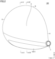
- golf club head 100 illustrated in Figs. 1 to 7 is a wood-type golf club head used for a driver golf club.
- Golf club head 100 may be a golf club head used for a fairway wood golf club or utility club.
- Fig. 1 is a front view of golf club head 100 that is set on a horizontal plane so as to form a predetermined loft angle and lie angle with the horizontal plane (hereinafter, referred to as a set state).
- a first direction Z illustrated in Figs. 1 and 7 is an upward direction.
- a second direction Y illustrated in Figs. 1 to 7 is a direction intersecting first direction Z and in parallel with the horizontal plane.
- a third direction X illustrated in Figs. 2 and 3 is a direction intersecting first direction Z and second direction Y and in parallel with the horizontal plane.
- golf club head 100 includes a face section 1, a crown section 2, a sole section 3, a heel section 4, a toe section 5, a back section 6, and a hosel section 7.
- face section 1 has a striking surface 1A and a back surface 1B positioned on the opposite side from striking surface 1A and facing the hollow section.
- face section 1 has an outer peripheral surface 1C connected to crown section 2, sole section 3, heel section 4, and toe section 5.
- Outer peripheral surface 1C connects striking surface 1A and back surface 1B and extends in a direction intersecting striking surface 1A and back surface 1B.
- an upper end surface section 1C2 positioned on an upper side in the set state is connected to crown section 2.
- a lower end surface section 1C3 positioned on a lower side in the set state is connected to sole section 3.
- a plurality of score lines are formed on striking surface 1A. Details of face section 1 will be described later.
- Crown section 2 is a section disposed above face section 1 in the set state. Crown section 2 serves as a top of golf club head 100. Crown section 2 is contiguous to face section 1. Crown section 2 has a lower end surface connected to upper end surface section 1C2 of face section 1.
- Sole section 3 is a section positioned below face section 1 in the set state. Sole section 3 serves as a bottom of golf club head 100. Sole section 3 has a sole surface 3A that comes into contact with the ground when hitting a ball. Sole surface 3A is a curved surface. Sole section 3 is contiguous to face section 1. Sole section 3 has an upper end surface connected to lower end surface section 1C3 of face section 1.
- Heel section 4 is a section extending from a lower end of hosel section 7 to sole section 3. Heel section 4 is contiguous to face section 1.
- Toe section 5 is a section connecting crown section 2 and sole section 3 on a side remote from hosel section 7.
- Back section 6 is a section smoothly connecting crown section 2 and sole section 3 on a side remotest from striking surface 1A in a direction perpendicular to striking surface 1A.
- a shaft 110 is connected to hosel section 7 of a golf club 200 (to be described later).
- a direction going from toe section 5 to heel section 4 along face section 1 is referred to as a toe-heel direction.
- a direction going from crown section 2 to sole section 3 along face section 1 is referred to as a crown-sole direction.
- a direction going from face section 1 to the back section is referred to as a face-back direction.
- golf club head 100 has a hollow section 101 formed therein.
- Hollow section 101 is separated from the outside of golf club head 100 by face section 1, crown section 2, sole section 3, heel section 4, toe section 5, back section 6, and hosel section 7.
- Hollow section 101 is positioned between face section 1 and back section 6 in the face-back direction, between crown section 2 and sole section 3 in the crown-sole direction, and between heel section 4 and toe section 5 in the toe-heel direction.
- a material of which face section 1, toe section 5, heel section 4, crown section 2, sole section 3, back section 6, and hosel section 7 are each made includes at least one selected from the group consisting of pure titanium (Ti), a titanium alloy, iron (Fe), stainless steel, and special steel, for example.
- the titanium alloy of which face section 1, toe section 5, heel section 4, crown section 2, sole section 3, back section 6, and hosel section 7 are each made may be any titanium alloy, and examples of such a titanium alloy include an ⁇ titanium alloy (for example, 5AL-2.5V), an ⁇ - ⁇ titanium alloy (for example, Ti-6Al-4V, Ti811 (Ti-8Al-1Mo-1V)), and a ⁇ titanium alloy (for example, SAT2041, Ti-15V-3Cr-3Sn-3AL).
- ⁇ titanium alloy for example, 5AL-2.5V
- an ⁇ - ⁇ titanium alloy for example, Ti-6Al-4V, Ti811 (Ti-8Al-1Mo-1V)
- a ⁇ titanium alloy for example, SAT2041, Ti-15V-3Cr-3Sn-3AL
- the stainless steel of which face section 1, crown section 2, sole section 3, heel section 4, toe section 5, back section 6, and hosel section 7 are each made may be any stainless steel, and examples of such stainless steel include austenitic stainless steel (for example, SUS304), martensitic stainless steel (for example, SUS431), and precipitation hardening stainless steel (for example, SUS630).
- austenitic stainless steel for example, SUS304
- martensitic stainless steel for example, SUS431
- precipitation hardening stainless steel for example, SUS630
- Examples of the special steel of which face section 1, crown section 2, sole section 3, heel section 4, toe section 5, back section 6, and hosel section 7 are each made include high-tensile steel, ultra-high-tensile steel, ausforming steel, maraging steel, and spring steel.
- Face section 1, crown section 2, sole section 3, heel section 4, toe section 5, back section 6, and hosel section 7 may be made of the same material or different materials.
- a material of which crown section 2, sole section 3, heel section 4, toe section 5, back section 6, and hosel section 7 is each made is an ⁇ - ⁇ titanium alloy, and a material of which face section 1 is made is a ⁇ titanium alloy.
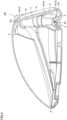
- Fig. 4 is a cross-sectional view as viewed from an arrow IV-IV in Fig. 2 .
- Fig. 4 is a cross-sectional view taken along a plane passing through the center of face section 1 in the toe-heel direction and extending in the crown-sole direction.
- Fig. 5 is a cross-sectional view as viewed from an arrow V-V in Fig. 2 .
- Fig. 5 is a cross-sectional view taken along a plane passing through a point closer to toe section 5 than the center of face section 1 in the toe-heel direction and extending in the crown-sole direction.
- Fig. 6 is a cross-sectional view as viewed from an arrow VI-VI in Fig. 1 .
- Fig. 6 is a cross-sectional view taken along a plane passing through the center of face section 1 in the crown-sole direction and extending in the toe-heel direction.
- Fig. 7 is a rear view of face section 1 alone as viewed from back surface 1B.
- solid lines illustrated inside the contour indicating outer peripheral surface 1C indicate ridge lines of an uneven structure formed on back surface 1B.
- face section 1 has a plurality of portions different in thickness.
- a thickness of face section 1 corresponds to a width of face section 1 in the direction perpendicular to striking surface 1A.
- a thickness distribution of face section 1 is determined based on the uneven structure on back surface 1B illustrated in Fig. 7 .
- First thick section 11 is disposed substantially at the center in the toe-heel direction.
- First thick section 11 has a first portion 11A and a second portion 11B.
- First portion 11A of first thick section 11 is disposed substantially at the center in the toe-heel direction and the crown-sole direction.
- Second portion 11B of first thick section 11 is disposed substantially at the center in the toe-heel direction.
- substantially at the center in the toe-heel direction means, for example, an area extending by 12 mm toward both the toe section and the heel section from a first imaginary center straight line passing through the center in the toe-heel direction and extending in the crown-sole direction.
- “Substantially at the center in the crown-sole direction” means, for example, an area extending by 12 mm toward both the crown section and the sole section from a second imaginary center straight line passing through the center in the crown-sole direction and extending in the toe-heel direction.
- First thick section 11 is, for example, the thickest portion of face section 1.
- Second thick section 12 is disposed closer to sole section 3 than first thick section 11. Second thick section 12 is disposed between first thick section 11 and sole section 3 in the crown-sole direction. Second thick section 12 is thinner than first thick section 11. Second thick section 12 is not in contact with sole section 3. A second thin portion 15 (to be described later) of thin section 13 is disposed between second thick section 12 and sole section 3.
- Thin section 13 is thinner than first thick section 11 and second thick section 12. Thin section 13 is disposed so as to surround the entire periphery of first thick section 11 and the entire periphery of second thick section 12.
- thin section 13 has a plurality of portions different in thickness.
- the thickest portion of thin section 13 is thinner than the thinnest portion of first thick section 11 and the thinnest portion of second thick section 12.
- Face section 1 smoothly changes in thickness at a connection portion between an outer edge of first thick section 11 and an outer edge of thin section 13.
- Face section 1 smoothly changes in thickness at a connection portion between an outer edge of second thick section 12 and the outer edge of thin section 13.
- the thickest portion of thin section 13 is, for example, the connection portion between the outer edge of first thick section 11 and the outer edge of thin section 13.
- thin section 13 includes a first thin portion 14, a second thin portion 15, a third thin portion 16, a fourth thin portion 17, and a fifth thin portion 18, which are defined based on the ridge lines or positions on back surface 1B illustrated in Fig. 7 .
- First thin portion 14 is disposed between first thick section 11 and second thick section 12.
- Second thin portion 15 is a portion of face section 1 connected to sole section 3.
- Second thin portion 15 is partially disposed between second thick section 12 and sole section 3.
- Third thin portion 16 is a portion of face section 1 connected to crown section 2.
- Third thin portion 16 is partially disposed between first thick section 11 and crown section 2.
- Fourth thin portion 17 is a portion of face section 1 connected to heel section 4.
- Fourth thin portion 17 is partially disposed between first thick section 11, second thick section 12, and first thin portion 14, and heel section 4.
- Fifth thin portion 18 is a portion of face section 1 connected to toe section 5.
- Fifth thin portion 18 is partially disposed between first thick section 11, second thick section 12, and first thin portion 14, and toe section 5.
- crown section 2, sole section 3, heel section 4, and toe section 5 are each connected to thin section 13 of face section 1.
- first portion 11A has a longitudinal direction coincident with the toe-heel direction and a lateral direction coincident with the crown-sole direction.
- Second portion 11B protrudes from a part at the center of first portion 11A in the longitudinal direction toward crown section 2.
- Second portion 11B has, for example, a longitudinal direction coincident with the toe-heel direction and a lateral direction coincident with the crown-sole direction.
- An end of first portion 11A adjacent to crown section 2 is connected to an end of second portion 11B adjacent to sole section 3.
- the maximum thickness of first portion 11A is equal to, for example, the maximum thickness of second portion 11B.
- first thick section 11 has an inverted T shape when face section 1 is viewed from back surface 1B.
- the inverted T shape is defined as a three-dimensional area including only first portion 11A having a longitudinal direction coincident with the toe-heel direction and a lateral direction coincident with the crown-sole direction, and second portion 11B protruding from a part at the center of first portion 11A in the longitudinal direction toward crown section 2.
- second portion 11B has, for example, a longitudinal direction coincident with the toe-heel direction and a lateral direction coincident with the crown-sole direction.
- face section 1 mainly includes first thick section 11, second thick section 12, and first thin portion 14, second thin portion 15, and third thin portion 16 of thin section 13.
- second thin portion 15 is, for example, thinner than first thin portion 14.
- a lower end surface of second thin portion 15 serves as lower end surface section 1C3 of face section 1.
- Third thin portion 16 is, for example, thinner than first thin portion 14.
- An upper end surface of third thin portion 16 serves as upper end surface section 1C2 of face section 1.
- At least either second thin portion 15 or third thin portion 16 is the thinnest portion of face section 1 in the cross section illustrated in Fig. 4 .
- Second thin portion 15 is, for example, thinner than third thin portion 16 and is thus the thinnest portion of face section 1 in the cross section illustrated in Fig. 4 .
- third thin portion 16 In the cross section illustrated in Fig. 4 , third thin portion 16, first thick section 11, first thin portion 14, second thick section 12, and second thin portion 15 are arranged side by side in the crown-sole direction from crown section 2 to sole section 3 in this order.
- face section 1 In the cross section illustrated in Fig. 4 , face section 1 gradually changes in thickness in the crown-sole direction.
- face section 1 mainly includes first thick section 11, first thin portion 14, second thin portion 15, and third thin portion 16, but does not include second thick section 12.
- face section 1 gradually decreases in thickness from first thick section 11 to sole section 3.
- third thin portion 16, first thick section 11, first thin portion 14, and second thin portion 15 are arranged side by side in the crown-sole direction from crown section 2 to sole section 3 in this order.
- thin section 13 gradually decreases in thickness from first thin portion 14 to second thin portion 15.
- face section 1 mainly includes first thick section 11, fourth thin portion 17, and fifth thin portion 18.
- fourth thin portion 17, first thick section 11, and fifth thin portion 18 are arranged side by side in the toe-heel direction from heel section 4 to toe section 5 in this order.
- Heel section 4 is connected to fourth thin portion 17.
- Toe section 5 is connected to fifth thin portion 18.
- face section 1 gradually changes in thickness in the toe-heel direction.
- first thick section 11, second thick section 12, first thin portion 14, and second thin portion 15 each have, for example, a longitudinal direction coincident with the toe-heel direction and a lateral direction coincident with the crown-sole direction.
- each of first thick section 11, second thick section 12, first thin portion 14, and second thin portion 15 in the toe-heel direction is not limited to any specific width.
- the width may be determined as desired in a manner that depends on the face shape.
- each of first thick section 11, second thick section 12, first thin portion 14, and second thin portion 15 in the crown-sole direction is not limited to any specific width.
- the width may be determined as desired in a manner that depends on the face shape.
- first thick section 11 has a thickness greater than or equal to 1.9 mm and less than or equal to 2.3 mm
- second thick section 12 has a thickness greater than or equal to 1.8 mm and less than or equal to 2.2 mm
- second thin portion 15 and third thin portion 16 each have a thickness greater than or equal to 1.7 mm and less than or equal to 2.1 mm, for example.
- first thick section 11 has a thickness greater than or equal to 3.4 mm and less than or equal to 3.8 mm
- second thick section 12 has a thickness greater than or equal to 2.5 mm and less than or equal to 2.9 mm
- second thin portion 15 and third thin portion 16 each have a thickness greater than or equal to 1.8 mm and less than or equal to 2.2 mm, for example.
- a method for manufacturing golf club head 100 may be any manufacturing method, but, for example, members each made by forging or casting are welded together to form golf club head 100.
- Crown section 2, sole section 3, heel section 4, and toe section 5 are formed in a single body by solid casting, for example.
- the single body has a hollow section and an opening formed therein, the opening communicating with the hollow section.
- Face section 1 covers the opening.
- Outer peripheral surface 1C of face section 1 is welded to an end surface of the opening of the molded body.
- a parting line is formed, due to casting, on an edge of the end surface of the opening adjacent to the hollow section, so that face section 1 can be defined as a portion including striking surface 1A and surrounded by the parting line.
- first thick section 11 and second thick section 12 are each entirely surrounded by thin section 13, so that thin section 13 of face section 1 is connected to sole section 3, specifically, to second thin portion 15.
- This can make a whole area between first thick section 11 and second thin portion 15 in face section 1 of golf club head 100 higher in resilience than the end adjacent to the sole section disclosed in PTL 1.
- This can make golf club head 100 larger in high-resilience area in the face section than the golf club head disclosed in PTL 1 in which the end adjacent to the sole section is formed as a thick section.
- Such a golf club head 100 makes face section 1 flexible even when a ball is hit at a point shifted from the sweet spot toward the sole section, that is, off-center shot, for example. This allows golf club head 100 to make a difference in distance between the sweet-spot shot and the off-center shot small as compared with the golf club head disclosed in PTL 1.
- Face section 1 of golf club head 100 further includes second thick section 12 disposed closer to sole section 3 than first thick section 11.
- face section 1 may become insufficient in durability.
- face section 1 does not include second thick section 12 and has a whole area between first thick section 11 and second thin portion 15 of face section 1 formed as a thin section, face section 1 may become too high in resilience.
- face section 1 includes second thin portion 15 and second thick section 12, thereby providing face section 1 with high durability and high resilience.
- third thin portion 16 of face section 1 is connected to crown section 2.
- Such a golf club head 100 makes face section 1 flexible even when a ball is hit at a point shifted from the sweet spot toward the crown section, that is, off-center shot, for example.
- golf club 200 includes golf club head 100, shaft 110, and a grip 120.
- Shaft 110 has one end attached to hosel section 7 of golf club head 100.
- Shaft 110 has the other end attached to grip 120.
- a result of evaluation of a characteristic time (CT) value of a face section will be described.
- golf club head 100 described above was prepared.
- a golf club head having a thick section formed extending from the center of the face section to the lower end of the face section and having a thin section formed only in an area adjacent to the crown section, the toe section, and the heel section relative to the thick section was prepared.
- a golf club head having neither the second thick section nor the thin section disposed so as to surround the entire periphery of the second thick section was prepared.
- the CT value is measured according to a procedure defined by the United States Golf Association (USGA).
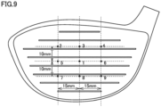
- Fig. 9 illustrates CT value measurement points 1 to 9 on the face section of a driver.
- the sweet spot was set as measurement point 1.
- the measurement points 2 to 9 were each set at a corresponding intersection of six imaginary straight lines drawn in a lattice pattern centered on measurement point 1.
- An interval in the toe-heel direction between three imaginary straight lines of the six imaginary straight lines extending in the crown-sole direction was set to 15 mm.
- An interval in the crown-sole direction between three imaginary straight lines extending in the toe-heel direction was set to 10 mm.
- measurement points 1, 5, 6 were set on the first thick section.
- measurement points 7, 8, 9 were set on second thin portion 15.
- measurement points 2, 3, 4 were set on third thin portion 16.
- measurement points 1, 3, 5, 6, 8 were set on the thick section, and measurement points 2, 4, 7, 9 were set on the thin section.
- Table 1 shows ratios obtained by normalizing the CT values measured at measurement points 1 to 9 of the example and the comparative example with the CT value measured at measurement point 1 of the example set to 1. [Table 1] Measurement point 1 2 3 4 5 6 7 8 9 Example 1.00 1.01 0.94 0.95 0.98 0.97 0.96 0.98 0.92 Comparative Example 0.98 0.96 0.92 0.96 0.95 0.97 0.93 0.91 0.90
- Table 1 shows that the example is higher than the comparative example in the ratios of measurement points 7, 8, 9 positioned closer to the sole section than measurement point 1.
- the ratio of the CT value of measurement point 8 of the example was greatly improved as compared with the ratio of the CT value of measurement point 8 of the comparative example, and was almost equal to the ratios of the CT values of measurement point 5 and measurement point 6 of the example arranged side by side with measurement point 1 in the toe-heel direction.
Landscapes
- Health & Medical Sciences (AREA)
- General Health & Medical Sciences (AREA)
- Physical Education & Sports Medicine (AREA)
- Life Sciences & Earth Sciences (AREA)
- Engineering & Computer Science (AREA)
- Wood Science & Technology (AREA)
- Golf Clubs (AREA)
Claims (6)
- Golfschlägerkopf, umfassend:einen Schlagflächenabschnitt (1);einen Kronenabschnitt;einen Sohlenabschnitt;einen Fersenabschnitt; undeinen Zehenabschnitt,wobei ein hohler Abschnitt, der von einer Außenseite getrennt ist, ausgebildet ist,der Schlagflächenabschnitt auf einer Rückfläche einen ersten dicken Abschnitt (11), der im Wesentlichen in einer Mitte in einer Zehen-Fersen-Richtung, die von dem Zehenabschnitt zu dem Fersenabschnitt verläuft, angeordnet ist, einen zweiten dicken Abschnitt (12), der näher an dem Sohlenabschnitt als der erste dicke Abschnitt angeordnet ist, und einen dünnen Abschnitt (13), der dünner als der erste dicke Abschnitt und der zweite dicke Abschnitt ist und so angeordnet ist, dass er einen gesamten Umfang des ersten dicken Abschnitts und einen gesamten Umfang des zweiten dicken Abschnitts umgibt, umfasst, undder erste dicke Abschnitt einen ersten Abschnitt (11A), der im Wesentlichen in einer Mitte sowohl in der Zehen-Fersen-Richtung als auch in einer Kronen-Sohlen-Richtung, die von dem Kronenabschnitt zu dem Sohlenabschnitt verläuft, angeordnet ist und eine Längsrichtung aufweist, die mit der Zehen-Fersen-Richtung zusammenfällt, und einen zweiten Abschnitt (11B), der von einem Teil in einer Mitte des ersten Abschnitts in der Längsrichtung zu dem Kronenabschnitt vorsteht, umfasst.
- Golfschlägerkopf gemäß Anspruch 1, wobei der erste dicke Abschnitt eine umgekehrte T-Form aufweist, wenn der Schlagflächenabschnitt von der Rückfläche aus betrachtet wird.
- Golfschlägerkopf gemäß Anspruch 1 oder 2, wobeider dünne Abschnitt mehrere Abschnitte aufweist, die sich in der Dicke unterscheiden, undein dickster Abschnitt des dünnen Abschnitts dünner als ein dünnster Abschnitt des ersten dicken Abschnitts und ein dünnster Abschnitt des zweiten dicken Abschnitts ist.
- Golfschlägerkopf gemäß Anspruch 3, wobeider dünne Abschnitt einen dritten Abschnitt, der zwischen dem ersten dicken Abschnitt und dem zweiten dicken Abschnitt in der Kronen-Sohlen-Richtung angeordnet ist, und einen vierten Abschnitt, der zwischen dem zweiten dicken Abschnitt und dem Sohlenabschnitt in der Kronen-Sohlen-Richtung angeordnet ist, umfasst, undder vierte Abschnitt dünner als der dritte Abschnitt ist.
- Golfschlägerkopf gemäß einem der Ansprüche 1 bis 4, wobei der Kronenabschnitt, der Sohlenabschnitt, der Fersenabschnitt und der Zehenabschnitt jeweils mit dem dünnen Abschnitt des Schlagflächenabschnitts verbunden sind.
- Golfschlägerkopf gemäß einem der Ansprüche 1 bis 5, wobei in der Zehen-Fersen-Richtung eine Breite des zweiten dicken Abschnitts schmaler als eine Breite des ersten dicken Abschnitts ist.
Applications Claiming Priority (2)
| Application Number | Priority Date | Filing Date | Title |
|---|---|---|---|
| JP2020116820A JP7028918B2 (ja) | 2020-07-07 | 2020-07-07 | ゴルフクラブヘッド |
| PCT/JP2021/025490 WO2022009890A1 (ja) | 2020-07-07 | 2021-07-06 | ゴルフクラブヘッド |
Publications (3)
| Publication Number | Publication Date |
|---|---|
| EP4162989A1 EP4162989A1 (de) | 2023-04-12 |
| EP4162989A4 EP4162989A4 (de) | 2024-06-12 |
| EP4162989B1 true EP4162989B1 (de) | 2025-03-19 |
Family
ID=79553160
Family Applications (1)
| Application Number | Title | Priority Date | Filing Date |
|---|---|---|---|
| EP21837544.2A Active EP4162989B1 (de) | 2020-07-07 | 2021-07-06 | Golfschlägerkopf |
Country Status (4)
| Country | Link |
|---|---|
| US (1) | US12053676B2 (de) |
| EP (1) | EP4162989B1 (de) |
| JP (1) | JP7028918B2 (de) |
| WO (1) | WO2022009890A1 (de) |
Family Cites Families (29)
| Publication number | Priority date | Publication date | Assignee | Title |
|---|---|---|---|---|
| US3814437A (en) * | 1973-01-30 | 1974-06-04 | S Winquist | Symbolically reinforced golf club head |
| JPH09239075A (ja) * | 1996-03-04 | 1997-09-16 | Mitsubishi Materials Corp | ゴルフクラブヘッド |
| US7273421B2 (en) | 2002-02-01 | 2007-09-25 | Dean L. Knuth | Golf club head |
| US6997820B2 (en) * | 2002-10-24 | 2006-02-14 | Taylor Made Golf Company, Inc. | Golf club having an improved face plate |
| JP4165282B2 (ja) | 2003-04-14 | 2008-10-15 | ヤマハ株式会社 | ゴルフクラブヘッド |
| JP2005124745A (ja) * | 2003-10-22 | 2005-05-19 | Sumitomo Rubber Ind Ltd | ゴルフクラブヘッド |
| US8696489B2 (en) * | 2004-10-07 | 2014-04-15 | Callaway Gold Company | Golf club head with variable face thickness |
| US7137907B2 (en) * | 2004-10-07 | 2006-11-21 | Callaway Golf Company | Golf club head with variable face thickness |
| US7387579B2 (en) * | 2006-06-28 | 2008-06-17 | O-Ta Precision Industry Co., Inc. | Golf club head |
| JP4326559B2 (ja) * | 2006-11-29 | 2009-09-09 | Sriスポーツ株式会社 | ゴルフクラブヘッド |
| US7575524B2 (en) * | 2006-12-06 | 2009-08-18 | Taylor Made Golf Company, Inc. | Golf clubs and club-heads comprising a face plate having a central recess and flanking recesses |
| JP5349006B2 (ja) * | 2008-10-29 | 2013-11-20 | ブリヂストンスポーツ株式会社 | ゴルフクラブヘッド |
| US8070623B2 (en) * | 2008-11-21 | 2011-12-06 | Nike, Inc. | Golf club head or other ball striking device having stiffened face portion |
| JP5342393B2 (ja) * | 2009-09-29 | 2013-11-13 | グローブライド株式会社 | ゴルフクラブ |
| JP5427598B2 (ja) | 2009-12-28 | 2014-02-26 | グローブライド株式会社 | ゴルフクラブ |
| JP5249257B2 (ja) | 2010-01-27 | 2013-07-31 | グローブライド株式会社 | ゴルフクラブ |
| JP2012071111A (ja) * | 2010-09-02 | 2012-04-12 | Yamaha Corp | ゴルフクラブヘッド |
| JP5185992B2 (ja) | 2010-11-02 | 2013-04-17 | ダンロップスポーツ株式会社 | ゴルフクラブ |
| JP2013027587A (ja) * | 2011-07-29 | 2013-02-07 | Dunlop Sports Co Ltd | ゴルフクラブヘッド |
| JP5785893B2 (ja) | 2012-03-28 | 2015-09-30 | グローブライド株式会社 | ゴルフクラブヘッド、及びゴルフクラブ |
| JP2014113367A (ja) | 2012-12-11 | 2014-06-26 | Bridgestone Sports Co Ltd | ゴルフクラブヘッド |
| US9981168B2 (en) * | 2013-05-06 | 2018-05-29 | Acushnet Company | Supported iron set |
| US11000742B2 (en) * | 2014-08-26 | 2021-05-11 | Parsons Xtreme Golf, LLC | Golf club heads and methods to manufacture golf club heads |
| US11083937B2 (en) * | 2015-06-30 | 2021-08-10 | Callaway Golf Company | Method of manufacturing golf club head having stress-reducing features |
| US10874915B2 (en) | 2017-08-10 | 2020-12-29 | Taylor Made Golf Company, Inc. | Golf club heads |
| US11033785B1 (en) * | 2020-03-24 | 2021-06-15 | Acushnet Company | Golf club head with improved variable thickness striking face |
| US12582879B2 (en) * | 2020-12-16 | 2026-03-24 | Taylor Made Golf Company, Inc. | Multi-piece golf club head |
| US12582880B2 (en) * | 2021-09-09 | 2026-03-24 | Acushnet Company | Golf club head with improved striking face |
| US20230347213A1 (en) * | 2021-09-09 | 2023-11-02 | Acushnet Company | Golf club head with improved striking face |
-
2020
- 2020-07-07 JP JP2020116820A patent/JP7028918B2/ja active Active
-
2021
- 2021-07-06 WO PCT/JP2021/025490 patent/WO2022009890A1/ja not_active Ceased
- 2021-07-06 EP EP21837544.2A patent/EP4162989B1/de active Active
- 2021-07-06 US US18/003,811 patent/US12053676B2/en active Active
Also Published As
| Publication number | Publication date |
|---|---|
| EP4162989A1 (de) | 2023-04-12 |
| JP2022014501A (ja) | 2022-01-20 |
| EP4162989A4 (de) | 2024-06-12 |
| WO2022009890A1 (ja) | 2022-01-13 |
| US20230226417A1 (en) | 2023-07-20 |
| JP7028918B2 (ja) | 2022-03-02 |
| US12053676B2 (en) | 2024-08-06 |
Similar Documents
| Publication | Publication Date | Title |
|---|---|---|
| US6716114B2 (en) | Wood-type golf club head | |
| US7857713B2 (en) | Wood-type golf club head | |
| US7137905B2 (en) | Golf club head | |
| US6783466B2 (en) | Golf club head | |
| EP1240924B1 (de) | Eisengolfschläger und golfschlägerset | |
| US6623374B1 (en) | Golf club head and set of golf clubs | |
| US7278925B2 (en) | Golf club head | |
| US7699719B2 (en) | Golf club head | |
| US8727908B2 (en) | Golf club head | |
| US7749103B2 (en) | Golf club head | |
| US8038546B2 (en) | Wood-type golf club head | |
| US20030232662A1 (en) | Golf club head with a face insert | |
| US20080261719A1 (en) | Golf club head | |
| US6875130B2 (en) | Wood-type golf club head | |
| KR20080054336A (ko) | 골프 클럽 헤드 | |
| US20080090676A1 (en) | Golf club head | |
| US10918918B2 (en) | Iron type golf club head | |
| US20190282864A1 (en) | Golf club head | |
| US11260276B2 (en) | Golf club head | |
| US12053676B2 (en) | Golf club head | |
| KR102239411B1 (ko) | 골프 클럽 헤드 | |
| US12161918B2 (en) | Golf club head | |
| JP2019165906A (ja) | ゴルフクラブセット | |
| US20230390616A1 (en) | Iron Golf Club Head and Iron Golf Club | |
| JP7032278B2 (ja) | ゴルフクラブヘッド |
Legal Events
| Date | Code | Title | Description |
|---|---|---|---|
| STAA | Information on the status of an ep patent application or granted ep patent |
Free format text: STATUS: THE INTERNATIONAL PUBLICATION HAS BEEN MADE |
|
| PUAI | Public reference made under article 153(3) epc to a published international application that has entered the european phase |
Free format text: ORIGINAL CODE: 0009012 |
|
| STAA | Information on the status of an ep patent application or granted ep patent |
Free format text: STATUS: REQUEST FOR EXAMINATION WAS MADE |
|
| 17P | Request for examination filed |
Effective date: 20221229 |
|
| AK | Designated contracting states |
Kind code of ref document: A1 Designated state(s): AL AT BE BG CH CY CZ DE DK EE ES FI FR GB GR HR HU IE IS IT LI LT LU LV MC MK MT NL NO PL PT RO RS SE SI SK SM TR |
|
| DAV | Request for validation of the european patent (deleted) | ||
| DAX | Request for extension of the european patent (deleted) | ||
| A4 | Supplementary search report drawn up and despatched |
Effective date: 20240514 |
|
| RIC1 | Information provided on ipc code assigned before grant |
Ipc: A63B 53/04 20150101AFI20240508BHEP |
|
| GRAP | Despatch of communication of intention to grant a patent |
Free format text: ORIGINAL CODE: EPIDOSNIGR1 |
|
| STAA | Information on the status of an ep patent application or granted ep patent |
Free format text: STATUS: GRANT OF PATENT IS INTENDED |
|
| INTG | Intention to grant announced |
Effective date: 20241014 |
|
| GRAS | Grant fee paid |
Free format text: ORIGINAL CODE: EPIDOSNIGR3 |
|
| GRAA | (expected) grant |
Free format text: ORIGINAL CODE: 0009210 |
|
| STAA | Information on the status of an ep patent application or granted ep patent |
Free format text: STATUS: THE PATENT HAS BEEN GRANTED |
|
| AK | Designated contracting states |
Kind code of ref document: B1 Designated state(s): AL AT BE BG CH CY CZ DE DK EE ES FI FR GB GR HR HU IE IS IT LI LT LU LV MC MK MT NL NO PL PT RO RS SE SI SK SM TR |
|
| REG | Reference to a national code |
Ref country code: GB Ref legal event code: FG4D |
|
| REG | Reference to a national code |
Ref country code: CH Ref legal event code: EP |
|
| P01 | Opt-out of the competence of the unified patent court (upc) registered |
Free format text: CASE NUMBER: APP_9672/2025 Effective date: 20250226 |
|
| REG | Reference to a national code |
Ref country code: DE Ref legal event code: R096 Ref document number: 602021027912 Country of ref document: DE |
|
| REG | Reference to a national code |
Ref country code: IE Ref legal event code: FG4D |
|
| PG25 | Lapsed in a contracting state [announced via postgrant information from national office to epo] |
Ref country code: RS Free format text: LAPSE BECAUSE OF FAILURE TO SUBMIT A TRANSLATION OF THE DESCRIPTION OR TO PAY THE FEE WITHIN THE PRESCRIBED TIME-LIMIT Effective date: 20250619 |
|
| PG25 | Lapsed in a contracting state [announced via postgrant information from national office to epo] |
Ref country code: FI Free format text: LAPSE BECAUSE OF FAILURE TO SUBMIT A TRANSLATION OF THE DESCRIPTION OR TO PAY THE FEE WITHIN THE PRESCRIBED TIME-LIMIT Effective date: 20250319 |
|
| REG | Reference to a national code |
Ref country code: LT Ref legal event code: MG9D |
|
| PG25 | Lapsed in a contracting state [announced via postgrant information from national office to epo] |
Ref country code: NO Free format text: LAPSE BECAUSE OF FAILURE TO SUBMIT A TRANSLATION OF THE DESCRIPTION OR TO PAY THE FEE WITHIN THE PRESCRIBED TIME-LIMIT Effective date: 20250619 |
|
| PG25 | Lapsed in a contracting state [announced via postgrant information from national office to epo] |
Ref country code: HR Free format text: LAPSE BECAUSE OF FAILURE TO SUBMIT A TRANSLATION OF THE DESCRIPTION OR TO PAY THE FEE WITHIN THE PRESCRIBED TIME-LIMIT Effective date: 20250319 |
|
| PG25 | Lapsed in a contracting state [announced via postgrant information from national office to epo] |
Ref country code: LV Free format text: LAPSE BECAUSE OF FAILURE TO SUBMIT A TRANSLATION OF THE DESCRIPTION OR TO PAY THE FEE WITHIN THE PRESCRIBED TIME-LIMIT Effective date: 20250319 |
|
| PG25 | Lapsed in a contracting state [announced via postgrant information from national office to epo] |
Ref country code: GR Free format text: LAPSE BECAUSE OF FAILURE TO SUBMIT A TRANSLATION OF THE DESCRIPTION OR TO PAY THE FEE WITHIN THE PRESCRIBED TIME-LIMIT Effective date: 20250620 Ref country code: BG Free format text: LAPSE BECAUSE OF FAILURE TO SUBMIT A TRANSLATION OF THE DESCRIPTION OR TO PAY THE FEE WITHIN THE PRESCRIBED TIME-LIMIT Effective date: 20250319 |
|
| REG | Reference to a national code |
Ref country code: NL Ref legal event code: MP Effective date: 20250319 |
|
| REG | Reference to a national code |
Ref country code: AT Ref legal event code: MK05 Ref document number: 1776497 Country of ref document: AT Kind code of ref document: T Effective date: 20250319 |
|
| PG25 | Lapsed in a contracting state [announced via postgrant information from national office to epo] |
Ref country code: NL Free format text: LAPSE BECAUSE OF FAILURE TO SUBMIT A TRANSLATION OF THE DESCRIPTION OR TO PAY THE FEE WITHIN THE PRESCRIBED TIME-LIMIT Effective date: 20250319 |
|
| PG25 | Lapsed in a contracting state [announced via postgrant information from national office to epo] |
Ref country code: SE Free format text: LAPSE BECAUSE OF FAILURE TO SUBMIT A TRANSLATION OF THE DESCRIPTION OR TO PAY THE FEE WITHIN THE PRESCRIBED TIME-LIMIT Effective date: 20250319 |
|
| PG25 | Lapsed in a contracting state [announced via postgrant information from national office to epo] |
Ref country code: SM Free format text: LAPSE BECAUSE OF FAILURE TO SUBMIT A TRANSLATION OF THE DESCRIPTION OR TO PAY THE FEE WITHIN THE PRESCRIBED TIME-LIMIT Effective date: 20250319 |
|
| PG25 | Lapsed in a contracting state [announced via postgrant information from national office to epo] |
Ref country code: ES Free format text: LAPSE BECAUSE OF FAILURE TO SUBMIT A TRANSLATION OF THE DESCRIPTION OR TO PAY THE FEE WITHIN THE PRESCRIBED TIME-LIMIT Effective date: 20250319 Ref country code: PT Free format text: LAPSE BECAUSE OF FAILURE TO SUBMIT A TRANSLATION OF THE DESCRIPTION OR TO PAY THE FEE WITHIN THE PRESCRIBED TIME-LIMIT Effective date: 20250721 |
|
| PGFP | Annual fee paid to national office [announced via postgrant information from national office to epo] |
Ref country code: DE Payment date: 20250722 Year of fee payment: 5 |
|
| PG25 | Lapsed in a contracting state [announced via postgrant information from national office to epo] |
Ref country code: IT Free format text: LAPSE BECAUSE OF FAILURE TO SUBMIT A TRANSLATION OF THE DESCRIPTION OR TO PAY THE FEE WITHIN THE PRESCRIBED TIME-LIMIT Effective date: 20250319 Ref country code: PL Free format text: LAPSE BECAUSE OF FAILURE TO SUBMIT A TRANSLATION OF THE DESCRIPTION OR TO PAY THE FEE WITHIN THE PRESCRIBED TIME-LIMIT Effective date: 20250319 |
|
| PGFP | Annual fee paid to national office [announced via postgrant information from national office to epo] |
Ref country code: GB Payment date: 20250724 Year of fee payment: 5 |
|
| PG25 | Lapsed in a contracting state [announced via postgrant information from national office to epo] |
Ref country code: AT Free format text: LAPSE BECAUSE OF FAILURE TO SUBMIT A TRANSLATION OF THE DESCRIPTION OR TO PAY THE FEE WITHIN THE PRESCRIBED TIME-LIMIT Effective date: 20250319 |
|
| PG25 | Lapsed in a contracting state [announced via postgrant information from national office to epo] |
Ref country code: EE Free format text: LAPSE BECAUSE OF FAILURE TO SUBMIT A TRANSLATION OF THE DESCRIPTION OR TO PAY THE FEE WITHIN THE PRESCRIBED TIME-LIMIT Effective date: 20250319 Ref country code: CZ Free format text: LAPSE BECAUSE OF FAILURE TO SUBMIT A TRANSLATION OF THE DESCRIPTION OR TO PAY THE FEE WITHIN THE PRESCRIBED TIME-LIMIT Effective date: 20250319 |
|
| PG25 | Lapsed in a contracting state [announced via postgrant information from national office to epo] |
Ref country code: RO Free format text: LAPSE BECAUSE OF FAILURE TO SUBMIT A TRANSLATION OF THE DESCRIPTION OR TO PAY THE FEE WITHIN THE PRESCRIBED TIME-LIMIT Effective date: 20250319 |
|
| PG25 | Lapsed in a contracting state [announced via postgrant information from national office to epo] |
Ref country code: SK Free format text: LAPSE BECAUSE OF FAILURE TO SUBMIT A TRANSLATION OF THE DESCRIPTION OR TO PAY THE FEE WITHIN THE PRESCRIBED TIME-LIMIT Effective date: 20250319 |
|
| PG25 | Lapsed in a contracting state [announced via postgrant information from national office to epo] |
Ref country code: IS Free format text: LAPSE BECAUSE OF FAILURE TO SUBMIT A TRANSLATION OF THE DESCRIPTION OR TO PAY THE FEE WITHIN THE PRESCRIBED TIME-LIMIT Effective date: 20250719 |
|
| REG | Reference to a national code |
Ref country code: DE Ref legal event code: R097 Ref document number: 602021027912 Country of ref document: DE |
|
| PG25 | Lapsed in a contracting state [announced via postgrant information from national office to epo] |
Ref country code: DK Free format text: LAPSE BECAUSE OF FAILURE TO SUBMIT A TRANSLATION OF THE DESCRIPTION OR TO PAY THE FEE WITHIN THE PRESCRIBED TIME-LIMIT Effective date: 20250319 |
|
| PLBE | No opposition filed within time limit |
Free format text: ORIGINAL CODE: 0009261 |
|
| STAA | Information on the status of an ep patent application or granted ep patent |
Free format text: STATUS: NO OPPOSITION FILED WITHIN TIME LIMIT |
|
| REG | Reference to a national code |
Ref country code: CH Ref legal event code: L10 Free format text: ST27 STATUS EVENT CODE: U-0-0-L10-L00 (AS PROVIDED BY THE NATIONAL OFFICE) Effective date: 20260128 |
|
| REG | Reference to a national code |
Ref country code: CH Ref legal event code: H13 Free format text: ST27 STATUS EVENT CODE: U-0-0-H10-H13 (AS PROVIDED BY THE NATIONAL OFFICE) Effective date: 20260224 |
|
| 26N | No opposition filed |
Effective date: 20251222 |
|
| PG25 | Lapsed in a contracting state [announced via postgrant information from national office to epo] |
Ref country code: LU Free format text: LAPSE BECAUSE OF NON-PAYMENT OF DUE FEES Effective date: 20250706 |
|
| REG | Reference to a national code |
Ref country code: BE Ref legal event code: MM Effective date: 20250731 |
|
| PG25 | Lapsed in a contracting state [announced via postgrant information from national office to epo] |
Ref country code: BE Free format text: LAPSE BECAUSE OF NON-PAYMENT OF DUE FEES Effective date: 20250731 |
|
| PG25 | Lapsed in a contracting state [announced via postgrant information from national office to epo] |
Ref country code: FR Free format text: LAPSE BECAUSE OF NON-PAYMENT OF DUE FEES Effective date: 20250731 |
|
| PG25 | Lapsed in a contracting state [announced via postgrant information from national office to epo] |
Ref country code: CH Free format text: LAPSE BECAUSE OF NON-PAYMENT OF DUE FEES Effective date: 20250731 |