EP4161817B1 - Servolenksystem für eine arbeitsmaschine - Google Patents
Servolenksystem für eine arbeitsmaschine Download PDFInfo
- Publication number
- EP4161817B1 EP4161817B1 EP20731458.4A EP20731458A EP4161817B1 EP 4161817 B1 EP4161817 B1 EP 4161817B1 EP 20731458 A EP20731458 A EP 20731458A EP 4161817 B1 EP4161817 B1 EP 4161817B1
- Authority
- EP
- European Patent Office
- Prior art keywords
- steering
- liquid
- power steering
- steering system
- valve
- Prior art date
- Legal status (The legal status is an assumption and is not a legal conclusion. Google has not performed a legal analysis and makes no representation as to the accuracy of the status listed.)
- Active
Links
Images





Classifications
-
- B—PERFORMING OPERATIONS; TRANSPORTING
- B62—LAND VEHICLES FOR TRAVELLING OTHERWISE THAN ON RAILS
- B62D—MOTOR VEHICLES; TRAILERS
- B62D5/00—Power-assisted or power-driven steering
- B62D5/06—Power-assisted or power-driven steering fluid, i.e. using a pressurised fluid for most or all the force required for steering a vehicle
- B62D5/30—Safety devices, e.g. alternate emergency power supply or transmission means to ensure steering upon failure of the primary steering means
- B62D5/32—Safety devices, e.g. alternate emergency power supply or transmission means to ensure steering upon failure of the primary steering means for telemotor systems
-
- B—PERFORMING OPERATIONS; TRANSPORTING
- B62—LAND VEHICLES FOR TRAVELLING OTHERWISE THAN ON RAILS
- B62D—MOTOR VEHICLES; TRAILERS
- B62D5/00—Power-assisted or power-driven steering
- B62D5/06—Power-assisted or power-driven steering fluid, i.e. using a pressurised fluid for most or all the force required for steering a vehicle
- B62D5/07—Supply of pressurised fluid for steering also supplying other consumers ; control thereof
-
- B—PERFORMING OPERATIONS; TRANSPORTING
- B62—LAND VEHICLES FOR TRAVELLING OTHERWISE THAN ON RAILS
- B62D—MOTOR VEHICLES; TRAILERS
- B62D5/00—Power-assisted or power-driven steering
- B62D5/06—Power-assisted or power-driven steering fluid, i.e. using a pressurised fluid for most or all the force required for steering a vehicle
- B62D5/09—Power-assisted or power-driven steering fluid, i.e. using a pressurised fluid for most or all the force required for steering a vehicle characterised by means for actuating valves
- B62D5/093—Telemotor driven by steering wheel movement
- B62D5/097—Telemotor driven by steering wheel movement gerotor type
Definitions
- the invention relates to a power steering system for a working machine.
- the invention is applicable on working machines within the fields of industrial construction machines or construction equipment, in particular wheel loaders. Although the invention will be described with respect to a wheel loader, the invention is not restricted to this particular machine, but may also be used in other working machines such as articulated haulers, excavators and backhoe loaders.
- a working machine In connection with transportation of heavy loads at construction sites or the like, a working machine is often used.
- the working machines may be utilized for transportations in connection with road or tunnel building, sand pits, mines, forestry and similar environments.
- a working machine is frequently operated with large and heavy loads in rough terrain and on slippery ground where no regular roads are present.
- the power steering system includes a hydraulic or electric actuator to increase the steering effort applied by the driver on the steering wheel and to reduce considerably the physical effort necessary to turn the wheels when the vehicle is stopped or moving slowly.
- Power steering systems are either electric or hydraulic.
- hydraulic systems there are the "conventional” hydraulic systems in which there is a mechanical link between the steering column and the steered wheels and the “full hydraulic” systems in which there is no mechanical link between the steering column and the wheels.
- a full hydraulic steering system is one in which a power steering pump pushes fluid through hydraulic hoses into and out of a steering cylinder that then turns the wheels.
- the conventional hydraulic systems include a steering gear whose purpose is to reinforce the torsional movement of the steering wheel to facilitate matters for the driver.
- the steering wheel movement is transmitted via a steering shaft to a ball worm.
- the ball worm is linked to a ball nut that is attached to the bottom of a reaction piston.
- the driver turns the steering wheel, it influences a valve in the steering gear and hydraulic fluid is forced under or over the reaction piston, depending on which way the driver turns the wheel.
- This construction is interesting in that it enables the driver to steer the vehicle even if the servo-pump (that is used for pumping fluid under or over the reaction piston) is out of action.
- the steering gear is replaced by a steering unit that comprises a steering valve and a metering device, which is also known as "gerotor".
- This steering valve is connected to the steering column so that, when the steering wheel is moved, oil is pumped by a hydraulic pump through the steering valve and subsequently through the metering device acting as a turbine.
- a metered oil flow is sent to either end of a hydraulic ram (or steering cylinder). The ram forces the wheels to turn according to the rotating direction of the steering wheel.
- US RE 25126 , US 4 514 152 and US 4 665 695 disclose examples of steering units.
- a main advantage of a full hydraulic steering system is that it allows to build a suspension that is unencumbered by a steering linkage such as a four-link. It is also powerful for turning big tires and simple in that it does not need a drag link to connect from a frame-mounted steering gearbox to the axle.
- Document GB1394808 shows a prior art system with the features of the preamble of claim 1.
- the driver must be able to control the machine in the event of an electrical failure, i.e. the steering system must be able to be manoeuvred even in the event of an electrical fault occurring in driving conditions, i.e. even when the hydraulic pump is off (not working).
- the steering unit is designed so that, if the hydraulic pump does not deliver oil, the torque applied by the driver to the steering column is transmitted to the metering device acting as a hand pump.
- the metering device can pump the fluid from one end of the hydraulic ram and conveys it to the other end, according to a closed loop (oil does not flow from or back to the tank). This results in turning the front wheels.
- the invention more particularly intends to remedy by proposing a power steering system allowing, on the one hand, to maintain a certain level of assistance when the pump of the oil circuit is not operative and on the other hand, to avoid the cavitation phenomenon inside the steering cylinder.
- An object of the invention is to provide a power steering system that can still provide an additional steering effort, even though no pressurized liquid flows in the supply line (pump not working), and that enables to avoid cavitation phenomenon when the machine is steered with the hydraulic pump off.
- the relief valve creates a back pressure inside the return line and the accumulator store a portion of pressurized oil, which makes it easier for the metering device (acting as a hand pump when there is no pressure in the supply line) to draw the liquid from the return line and to recirculate it into the system.
- the accumulator forms an additional source of liquid when the hydraulic pump is not working. Indeed, in such configuration, the metering device can draw liquid from the accumulator, which enables to have enough liquid flowing into the compartment of the steering cylinder that is in expansion (with respect to the position of the piston) and therefore to avoid cavitation.
- the invention also concerns a working machine as defined in the claims 11 to 14.
- Figure 2 represents a working machine 4.
- the machine 4 is a wheel loader, in particular an articulated wheel loader.
- the machine 4 comprises a rear unit 6 and a front unit 8 that are hinged one with the other around an axis Z-Z' that is perpendicular to the ground in a normal configuration, i.e. vertical.
- the machine includes an articulated joint arrangement that enables the front unit 8 to turn relative to the rear unit 6.
- the front unit 8 and the rear unit 6 each comprises a respective pair of wheels. Contrary to other types of heavy-duty vehicles, in an articulated wheel loader, the front axle and the rear axle do not remain parallel one with the other. One benefit of using such articulation is that the driver can manoeuvre in much smaller areas than wheel loaders equipped with a rigid frame. However, the invention is obviously applicable to wheel loaders equipped with a single rigid frame, in which only the front wheels pivot during a turn.
- the machine 4 comprises a power steering system 2 that helps the driver to steer the vehicle by providing an additional steering effort, making it easier for the driver to turn.
- the power steering system 2 includes at least one steering cylinder 10, comprising two compartments separated by a piston 11.
- the piston is attached to a piston rod 13 that is linked to the articulation joint arrangement of the machine 4.
- the steering cylinder 10 is a double acting cylinder, which means that each compartment can receive pressurized liquid so as to control the movement of the piston rod.
- the power steering system 2 may include two or more steering cylinders.
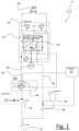
- the power steering system 2 further includes a liquid tank 12, a steering unit 14, a hydraulic pump 22, for pumping liquid from the tank 12 to the steering unit 14 through a supply line 24 (also known as “pump line”), a return line 26 (also known as “tank line”) through which the liquid can flow from the steering unit 14 back to the tank 12 and two control lines 30 and 32, respectively connecting the steering unit 14 to the two compartments (left and right) of the steering cylinder 10.
- the power steering system 2 is a full hydraulic system in which there is no mechanical link between the steering column and the wheels. This means that the pump 22 pushes fluid through hydraulic hoses into and out of the steering cylinder 10 that then turns the front unit 8 relative to the rear unit 6.
- the liquid tank 12 is an oil tank.
- the hydraulic pump 22 is the only oil pump of the working machine 4, which means that the hydraulic pump is used to supply other hydraulic systems than steering, such as the implement actuators.
- the power steering system 2 further includes a priority valve 44 designed so that the hydraulic pump 22 supplies the power steering system as a priority. More precisely, the priority valve 44 is designed to allow liquid flow to other hydraulic systems than steering only when the pressure of the liquid conveyed by the pump 22 (available pressure) is greater than or equal to a specified level. When the available pressure drops below said specified level, the priority valve 44 will close, leaving flow available to the power steering actuator 10.
- the priority valve 44 is well known as such, that is why it is not detailed further herein.
- the system 2 further includes a hydraulic control valve 60 whose function is to control the implement of the machine (working tool), such as a bucket.
- the machine 4 includes a full electric powertrain (not shown), which means that the machine 4 does not include any internal combustion engine.
- the hydraulic pump 22 is driven by an electric motor.
- the invention is also applicable to a fuel-powered working machine in which the hydraulic pump is mechanically linked to the engine crankshaft, for example through a belt.
- the steering unit 14 includes a steering valve 16 and a metering device 18, for supplying one compartment (left or right) of the steering cylinder 10 with a metered flow of liquid.
- the steering valve 16 is a rotary valve comprising an input shaft 21 connected to a steering wheel 20.
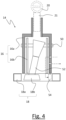
- the metering device 18 is a gerotor (which is derived from "generated rotor") consisting of an inner rotor 18b and an outer rotor 18a.
- the inner rotor has n teeth, while the outer rotor has n+1 teeth; with n defined as a natural number greater than or equal to 2.
- the geometry of the two rotors partitions the volume between them into n different dynamically-changing volumes. During the rotation cycle, each of these volumes changes continuously, so any given volume first increases, and then decreases. An increase creates a vacuum. This vacuum creates suction, and hence, this part of the cycle is where the inlet is located. As a volume decreases compression occurs. During this compression period, a fluid can be pumped.
- gerotor 18 can also be designated as "gerotor mechanism”.
- the rotary valve includes a housing (not shown) inside which is arranged a cylindrical spool 16a.
- the spool 16a can be provided with splines in which a rotary shaft 21 of a steering wheel 20 can be snugly fitted.
- the spool 16a is freely rotatable inside the housing.
- a sleeve 16b is arranged inside the spool 16a.
- a transverse pin 50 rotationally couples the sleeve 16b with the spool 16a.
- the sleeve 16b delimits slots for the passage of the pin 50, which means that the spool 16a can rotate relative to the sleeve 16b over a certain angular displacement (or clearance).
- a spring mechanism (not shown) is used to return the sleeve 16b in a neutral configuration relative to the spool 16a.
- the inner rotor 18b is mechanically linked to the input shaft 21.
- a transmission shaft 52 also known as “dog bone” connects the inner rotor 18b to the pin 50, and therefore to the spool 16a which, itself, is connected to the input shaft 21.
- the above-mentioned spring mechanism maintains the relative position between the spool 16a and the sleeve 16b in a neutral position.
- the spool 16a is rotated and forms in conjunction with the sleeve 16b a path for the passage of liquid.
- the pressurized liquid flows successively through a pump port and is supplied to the vacant spaces 54 between the stator 18a and the rotor 18b of the gerotor mechanism 18.
- the supply of the pressurized liquid into the gerotor mechanism 18 allows the rotor 18b to make an orbital motion in the clockwise direction (resp. counterclockwise direction) while rotating on its own axis in the counterclockwise direction (resp. clockwise direction), with the result that the vacant spaces 54 are contracted.
- the pressurized liquid fed out of the gerotor mechanism 18 is supplied, into one compartment (left or right, depending on the rotation direction of the steering wheel 20) of the steering cylinder 10.
- the gerotor 18 therefore serves as a hydraulic turbine (or hydraulic motor).
- the sleeve 16b is rotated in a follow-up manner relative to the rotation of the spool 16a and, when the steering wheel stops its rotation, the sleeve 16b and the spool 16a are brought to a neutral state, with the result that the supply of the pressurized liquid to the steering cylinder 10 is stopped.
- Control spool 16a of the control valve is rotated via the steering column in relation to control sleeve 16b. This opens cross-sections between the spool 16a and the sleeve 16b.
- the pressurized oil acts on the rotor 18 and sets the latter into motion.
- the oil is then fed via the rotor set to the steering cylinder.
- the rotation of the rotor acts on the sleeve 16b, which then follows the rotary movement of the spool 16a.
- the size of the opened cross section depends on the speed of the steering wheel and/or on the steering pressure. If the steering movement is interrupted and the spool 16a is at a standstill, the oil, which still flows through the opened cross-sections to the rotor 18b, causes the rotor 18b and hence the sleeve 16b to continue to rotate a bit.
- a centering spring brings and holds the spool 16a and sleeve 16b in a neutral position to each other.
- the rotary valve In the event of an oil supply failure, the rotary valve operates as hand pump. In this operational state, oil can be sucked from the tank via a suction check valve, which prevents that air gets into the system. During normal operation, this valve also prevents shock or kick backs on the steering wheel caused by excessive external steering forces.
- Figure 6 shows a right turn configuration.
- the path of liquid is represented by the arrows.
- the movement of the steering wheel 20 in the clockwise direction makes the rotary valve 16 to connect the supply line 24 to the inlet side of the gerotor 18.
- the control line 30 connected to the left compartment of the steering cylinder 10 is connected to the outlet side of the gerotor 18 (acting as a hydraulic motor).
- the rotary valve 16 connects the control line 32 connected to the right compartment of the steering cylinder 10 to the return line 26.
- pressurized liquid flows inside the left compartment of the steering cylinder 10, while liquid inside the right compartment flows back to the tank 12 through the return line 26. This leads to a movement of the piston 11 (and consequently of the piston rod 13) to the right direction, as shown by the big arrow above the cylinder 10.
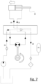
- Figure 7 shows a left turn configuration, in which the arrows also represent the path of liquid.
- the movement of the steering wheel 20 in the counter-clockwise direction makes the rotary valve 16 to connect the supply line 24 to the inlet side of the gerotor 18.
- the control line 32 connected to the right compartment of the steering cylinder 10 is connected to the outlet side of the gerotor 18 (acting as a hydraulic motor).
- the rotary valve 16 connects the control line 30 connected to the left compartment of the steering cylinder 10 to the return line 26. Accordingly, pressurized liquid flows inside the right compartment of the steering cylinder 10, while liquid inside the left compartment is drawn back to the tank 12 through the return line 26. This leads to a movement of the piston 11 (and consequently of the piston rod 13) to the left direction.
- the gerotor mechanism 18 serves as a hydraulic pump (fail-safe function).
- the gerotor 18 can be used to pump liquid from one compartment of the steering cylinder 10 to the other compartment.
- the power steering system includes a recirculation line 28 connecting the return line 26 to the supply line 24.
- a check valve 44 is arranged on said recirculation line 28 to prevent liquid from flowing from the supply line 24 to the return line 26.
- an additional check valve 42 preferably a spring-loaded check valve, is arranged on the supply line 24 for preventing liquid from flowing from the steering unit 14 back to the pump 22.
- the liquid that is drawn by the gerotor 18 acting as a hand pump does not flow back to the tank 12 but is recirculated in the system:
- the gerotor 18 draws the liquid flowing in the return line 26, using the recirculation line 28.
- Pressurized liquid delivered in output of the gerotor 18 is sent to the opposed compartment of the steering cylinder to make the machine 4 turn.
- Figure 8 shows a configuration in which the supply line 24 is not pressurized, i.e. a configuration in which the hydraulic pump 22 is not able to pump any liquid from the tank 12 to the steering unit 14.
- such configuration can happen when the battery (not shown) of the working machine 4 is discharged.
- the arrows also represent the path of liquid.
- figure 8 represents a configuration in which the steering wheel 20 is turned to the counter-clockwise direction (Left turn).
- the movement of the steering wheel 20 in the counter-clockwise direction makes the gerotor 18 to draw liquid from the left compartment of the steering cylinder 10, successively through the control line 30, the return line 26 and the recirculation line 28, and to pump it in direction of control line 32 to fill in the right compartment of the steering cylinder 10 with a pressurized liquid flow.
- the control line 32 connected to the right compartment of the steering cylinder 10 is connected to the outlet side of the gerotor 18 (acting as a hydraulic pump).
- pressurized liquid flows inside the right compartment of the steering cylinder 10, while liquid inside the left compartment is recirculated into the system, through the recirculation line 28.
- the power steering system 2 further comprises a liquid accumulator 34 connected through a branch 35 to the return line 26.
- branch 35 extends between a connection point 38 arranged on the return line 26 and the accumulator 34.
- the accumulator 34 includes one port connected to the branch 35. This port serves both for discharging the accumulated liquid and refilling the accumulator 34, when appropriate.
- the liquid accumulator 34 which is an oil accumulator, creates a backpressure inside the return line 26, which makes the liquid inside the return line 26 easier to draw (or pump) by the gerotor 18 (in comparison with the systems of prior art in which no accumulator is arranged on the "tank line” side).
- pressurized liquid is therefore discharged from the accumulator 34 to the inlet side of the gerotor 18, successively through the tank line 26 and the recirculation line 28.
- the gerotor 18 then delivers a metered flow of liquid to the right compartment of the steering cylinder 10, through control line 32.
- the size of the accumulator 34 is chosen to be superior to that of the steering cylinder 10, so that the accumulator 34 can never be emptied and can generate a backpressure during the whole range of displacement of the steering wheel 20.
- the accumulator 34 provides another advantage, which is to avoid the phenomenon of cavitation inside the steering cylinder 10.
- the steering system of the machine 4 is built according to a non-reaction design, which means that, contrary to other road vehicles, such as trucks or passenger cars, the steering does not come back to a straight position after a turn, when the driver stops turning the wheel.
- the steering system does not react as a function of external forces, such as the ones applied by the road or coming from the own weight of the machine.
- all orifices of the hydraulic system are closed off and the steering rod stays as it is: the steering angle does not change.
- the driver needs to move the steering wheel 20 in the opposite direction to move the front unit 8 back to a straight position relative to the rear unit 6.
- the metering device 18 draws oil from the compartment of the steering cylinder that is in compression and pumps oil to the compartment of the steering cylinder that is in expansion. Since oil is drawn from the compartment that is in compression, pressure unbalance occurs between the right and left compartments, which makes the piston to move. Without the additional source of pressurized liquid supplied by the accumulator, the metering device might not be able to convey enough oil inside the compartment that is in expansion in order to keep it full of liquid. In other words, the amount of liquid flowing inside the compartment in expansion might not be high enough to keep it full of liquid and some vacuum might appear. This can be especially critical when the volume of the compartment in expansion is much higher than that of the compartment in compression, i.e. when the steering angle increases.
- the accumulator 34 can be used to supply the compartment of the steering cylinder that is in expansion with an additional amount of pressurized liquid, thereby avoiding any creation of vacuum inside the steering cylinder. Without any cavitation, the driver has the feeling that the wheels remain connected to the steering system, which complies with the requirements of the concerned regulation (ISO 5010).
- the steering system of the machine 4 can also be built according to a load-reaction design, which means that, as other road vehicles, such as trucks or passenger cars, the steering system reacts as a function of external forces, such as the ones applied by the road or coming from the own weight of the machine.
- the steering rod 13 can move as a function of external forces applying on the steering system.
- the piston 11 that is part of the steering rod 13 pushes liquid stored inside one compartment (in compression) and vacuum can appear in the other compartment (the one in expansion) if the amount of liquid that is simultaneously introduced into this compartment in expansion is not high enough to fill in the vacuum space.
- the accumulator 34 enables to make sure that enough liquid is pumped to the compartment in expansion and that no cavitation occurs.
- the amount of liquid to be pumped inside the compartment in expansion is lower than that which is needed to increase the steering angle. Accordingly, the liquid drawn from the compartment that is in compression is usually sufficient for feeding the other compartment of the steering cylinder 10, which means that it is no more necessary to draw liquid from the accumulator 34. In such configuration, which is represented on figure 9 , no more liquid is drawn from the accumulator 34. More precisely, a portion of the liquid drawn from the compartment in expansion is recirculated in the system (through line 28), while the other portion flows back in the tank line 26 and can be used to recharge the accumulator 34.
- the accumulator 34 is not actively controlled: It is discharged and recharged automatically, depending on pressure conditions in the pump line 24. One can speak of a passive control.
- a relief valve 36 is advantageously arranged on the return line 26 between the liquid tank 12 and a connection point 38 of the accumulator 34.
- the relief valve 36 is a spring-loaded check valve.
- This relief valve 36 enables to create a backpressure inside the tank line 26.
- the relief valve 36 enables the liquid to flow from the steering unit 14 to the tank 12 only when a pressure threshold, e.g. 3 bar (relative pressure) has been reached.
- a pressure threshold e.g. 3 bar (relative pressure)
- the relief valve 36 is designed to open at a predetermined set pressure, e.g. 3 bar. This is achieved by using a valve spring capable of providing enough force to maintain the valve 36 closed as long as the pressure upstream of the valve 36 is below said pressure threshold.
- a liquid filter 40 is arranged on the return line 26 between the liquid tank 12 and the connection point 38 of the accumulator 34, preferably between the liquid tank 12 and the relief valve 36.
Landscapes
- Engineering & Computer Science (AREA)
- Chemical & Material Sciences (AREA)
- Combustion & Propulsion (AREA)
- Transportation (AREA)
- Mechanical Engineering (AREA)
- Power Steering Mechanism (AREA)
Claims (14)
- Servolenkungssystem (2) für eine Arbeitsmaschine (4), wobei das Servolenkungssystem umfasst:- mindestens einen Lenkzylinder (10), der zwei durch einen Kolben (11) getrennte Kammern aufweist,- einen Flüssigkeitsbehälter (12),- eine Lenkeinheit (14) mit einem Lenkventil (16) und einer Dosiervorrichtung (18) zur Versorgung einer Kammer des Lenkzylinders mit einem dosierten Flüssigkeitsstrom,- eine Hydraulikpumpe (22), die über eine Versorgungsleitung (24) Flüssigkeit aus dem Flüssigkeitstank zur Lenkeinheit pumpt,- eine Rücklaufleitung (26), durch die die Flüssigkeit von der Lenkeinheit zurück in den Flüssigkeitsbehälter fließen kann,- eine Rückführleitung (28), die die Rückführleitung mit der Zuführleitung verbindet, wobei ein Rückschlagventil (44) in der Rückführleitung angeordnet ist, um zu verhindern, dass Flüssigkeit von der Zuführleitung zur Rückführleitung fließt,- zwei Steuerleitungen (30, 32), die jeweils die Lenkeinheit mit den beiden Kammern des Lenkzylinders verbinden,dadurch gekennzeichnet, dass das Servolenkungssystem ferner einen Flüssigkeitsspeicher (34) umfasst, der über eine Abzweigung (35) mit der Rücklaufleitung (26) verbunden ist, und dass ein Überdruckventil (36) in der Rücklaufleitung (26) zwischen dem Flüssigkeitstank (12) und einem Anschlusspunkt (38) des Speichers (34) angeordnet ist.
- Servolenkungssystem nach Anspruch 1, dadurch gekennzeichnet, dass das Überdruckventil (36) ein federbelastetes Rückschlagventil ist.
- Servolenkungssystem nach Anspruch 1 oder 2, dadurch gekennzeichnet, dass an der Rücklaufleitung (26) zwischen dem Flüssigkeitstank (12) und dem Anschlusspunkt (38) des Speichers, vorzugsweise zwischen dem Flüssigkeitstank (12) und dem Überdruckventil (36), ein Flüssigkeitsfilter (40) angeordnet ist.
- Servolenkungssystem nach einem der vorhergehenden Ansprüche, dadurch gekennzeichnet, dass die Hydraulikpumpe (22) von einem Elektromotor angetrieben wird.
- Servolenkungssystem nach einem der vorhergehenden Ansprüche, dadurch gekennzeichnet, dass der Lenkzylinder (10) ein doppelt wirkender Zylinder ist.
- Servolenkungssystem nach einem der vorhergehenden Ansprüche, dadurch gekennzeichnet, dass in der Versorgungsleitung (24) ein zusätzliches Rückschlagventil (42), vorzugsweise ein federbelastetes Rückschlagventil, angeordnet ist, das ein Zurückfließen von Flüssigkeit von der Lenkeinheit (14) zur Pumpe (22) verhindert.
- Servolenkungssystem nach einem der vorhergehenden Ansprüche, dadurch gekennzeichnet, dass das Volumen des Akkumulators (34) größer oder gleich dem Volumen des Lenkzylinders (10) ist.
- Servolenkungssystem nach einem der vorhergehenden Ansprüche, dadurch gekennzeichnet, dass das Lenkventil (16) ein Drehventil ist, das eine mit einem Lenkrad (20) verbundene Eingangswelle (21) umfasst.
- Servolenkungssystem nach dem vorhergehenden Anspruch, dadurch gekennzeichnet, dass die Dosiervorrichtung (18) ein Gerotor ist, der aus einem inneren Rotor (18b) und einem äußeren Rotor (18a) besteht, und dass der innere Rotor (18b) mechanisch mit der Eingangswelle (21) verbunden ist.
- Servolenkungssystem nach einem der vorhergehenden Ansprüche, dadurch gekennzeichnet, dass das System ferner ein Prioritätsventil (44) umfasst, das so ausgelegt ist, dass die Hydraulikpumpe das Servolenkungssystem vorrangig versorgt.
- Arbeitsmaschine (4), dadurch gekennzeichnet, dass sie ein Servolenkungssystem (2) nach einem der vorhergehenden Ansprüche umfasst.
- Arbeitsmaschine nach dem vorhergehenden Anspruch, dadurch gekennzeichnet, dass die Maschine nur eine Hydraulikpumpe (22) umfasst.
- Arbeitsmaschine nach Anspruch 11 oder 12, dadurch gekennzeichnet, dass die Maschine einen vollelektrischen Antriebsstrang aufweist.
- Arbeitsmaschine nach einem der Ansprüche 11 bis 13, dadurch gekennzeichnet, dass die Maschine ein Radlader, insbesondere ein knickgelenkter Radlader ist.
Applications Claiming Priority (1)
| Application Number | Priority Date | Filing Date | Title |
|---|---|---|---|
| PCT/EP2020/065807 WO2021249614A1 (en) | 2020-06-08 | 2020-06-08 | A power steering system for a working machine |
Publications (3)
| Publication Number | Publication Date |
|---|---|
| EP4161817A1 EP4161817A1 (de) | 2023-04-12 |
| EP4161817B1 true EP4161817B1 (de) | 2024-08-28 |
| EP4161817C0 EP4161817C0 (de) | 2024-08-28 |
Family
ID=71069849
Family Applications (1)
| Application Number | Title | Priority Date | Filing Date |
|---|---|---|---|
| EP20731458.4A Active EP4161817B1 (de) | 2020-06-08 | 2020-06-08 | Servolenksystem für eine arbeitsmaschine |
Country Status (4)
| Country | Link |
|---|---|
| US (1) | US12509144B2 (de) |
| EP (1) | EP4161817B1 (de) |
| CN (1) | CN115667053A (de) |
| WO (1) | WO2021249614A1 (de) |
Family Cites Families (20)
| Publication number | Priority date | Publication date | Assignee | Title |
|---|---|---|---|---|
| US2984215A (en) | 1958-11-25 | 1961-05-16 | Controller for fluid pressure operated devices | |
| DE2263417A1 (de) | 1972-12-27 | 1974-07-18 | Deere & Co | Hydrostatische lenkung fuer kraftfahrzeuge |
| US3976158A (en) * | 1975-04-25 | 1976-08-24 | Caterpillar Tractor Co. | Power steering system for electric-drive lift truck |
| US4190130A (en) * | 1978-09-11 | 1980-02-26 | Unit Rig & Equipment Co. | Dual steering system for off-highway vehicles |
| US4217968A (en) * | 1978-10-04 | 1980-08-19 | Caterpillar Tractor Co. | Closed center emergency steering with accumulator source |
| US4665695A (en) * | 1981-03-13 | 1987-05-19 | Trw Inc. | Hydrostatic load sense steering system |
| US4514152A (en) * | 1982-08-02 | 1985-04-30 | Tokyo Keiki Company, Ltd. | Gerotor power steering apparatus with driven rotary sleeve valve |
| US4574904A (en) * | 1983-02-24 | 1986-03-11 | Fmc Corporation | Auxilliary steering system |
| US4781219A (en) * | 1986-10-10 | 1988-11-01 | Eaton Corporation | Fluid controller and dampening fluid path |
| US5080135A (en) * | 1990-10-24 | 1992-01-14 | Eaton Corporation | Large deflection angle rotary modulation steering valve |
| DE19842066A1 (de) | 1998-09-15 | 2000-03-23 | Daimler Chrysler Ag | Lenksystem für ein Fahrzeug |
| DE10156598A1 (de) | 2001-11-17 | 2003-05-28 | Still Gmbh | Mobile Arbeitsmaschine mit einer elektrisch angetriebenen Lenkpumpe |
| JP4315881B2 (ja) * | 2004-09-10 | 2009-08-19 | 株式会社日立製作所 | パワーステアリング装置 |
| GB2448914B (en) * | 2007-05-03 | 2012-03-07 | Jcb Landpower Ltd | Vehicle |
| US9248854B2 (en) * | 2013-04-04 | 2016-02-02 | Caterpillar Inc. | Electro-hydraulic steering control system |
| US9867325B2 (en) | 2014-04-29 | 2018-01-16 | Cnh Industrial America Llc | Work vehicle with hydraulic assist for power off steering |
| US10259493B2 (en) * | 2016-12-09 | 2019-04-16 | Caterpillar Inc. | Emergency steering pump system for a machine |
| US10144450B1 (en) | 2017-06-05 | 2018-12-04 | Caterpillar Inc. | Hydraulic system for a steering system of a vehicle |
| DE102017213407A1 (de) | 2017-08-02 | 2019-02-07 | Jungheinrich Aktiengesellschaft | Hydraulisches Lenksystem |
| CN109109970A (zh) * | 2018-09-07 | 2019-01-01 | 华南理工大学 | 一种包含隔绝回路的线控液压转向装置 |
-
2020
- 2020-06-08 WO PCT/EP2020/065807 patent/WO2021249614A1/en not_active Ceased
- 2020-06-08 EP EP20731458.4A patent/EP4161817B1/de active Active
- 2020-06-08 US US17/927,946 patent/US12509144B2/en active Active
- 2020-06-08 CN CN202080101349.8A patent/CN115667053A/zh active Pending
Also Published As
| Publication number | Publication date |
|---|---|
| US12509144B2 (en) | 2025-12-30 |
| US20230227099A1 (en) | 2023-07-20 |
| CN115667053A (zh) | 2023-01-31 |
| EP4161817C0 (de) | 2024-08-28 |
| EP4161817A1 (de) | 2023-04-12 |
| WO2021249614A1 (en) | 2021-12-16 |
Similar Documents
| Publication | Publication Date | Title |
|---|---|---|
| US7444809B2 (en) | Hydraulic regeneration system | |
| US20130074487A1 (en) | Drive system having at least one hydraulic actuator | |
| US6761234B1 (en) | Skid steer vehicle with steerable suspension | |
| US9764759B2 (en) | Electrohydraulic steer-by-wire steering system | |
| US3834278A (en) | Power steering system with auxiliary power capability | |
| US4766727A (en) | Fluid control valve | |
| US7845458B2 (en) | Control system for frame-steering of a vehicle and method for controlling two steering cylinders in a frame-steered vehicle | |
| WO1997047511A1 (en) | Hydrostatic steering device with two steering systems | |
| EP1048549B1 (de) | Hydrostatische Kraftfahrzeugservolenkung für erhöhte Geschwindigkeit | |
| EP4161817B1 (de) | Servolenksystem für eine arbeitsmaschine | |
| US4262580A (en) | Power steering system with auxiliary power capability | |
| DE102012112381A1 (de) | Antriebsachse eines Fahrzeugs mit einer einen hydraulischen Druckmittelspeicher umfassenden Energierückgewinnungseinrichtung | |
| EP2303668B1 (de) | Vorrichtung zur unterstützung einer geradlinigen bewegung für eine arbeitsmaschine | |
| JP3508816B2 (ja) | パワーステアリング装置 | |
| KR100371734B1 (ko) | 동력 조향장치 | |
| CN108349531A (zh) | 转向系统和用于运行转向系统的方法 | |
| US4222452A (en) | Power steering mechanism for cotton pickers | |
| USRE30291E (en) | Power steering system with auxiliary power capability | |
| JP6972194B2 (ja) | 吸引車の油圧駆動装置 | |
| EP2567850B1 (de) | Hydraulisches Nutzfahrzeug mit Allradantrieb | |
| US3848693A (en) | Dual hydraulic power steering system with hydrostatic control | |
| JPS5939338B2 (ja) | 流体圧力式車両駆動装置 | |
| SE529526C2 (sv) | Styrsystem för ramstyrning av ett fordon och förfarande för styrning av två styrcylindrar hos ett ramstyrt fordon | |
| JP3905669B2 (ja) | 動力舵取装置 | |
| JPS59167334A (ja) | 車両の前輪補助駆動装置 |
Legal Events
| Date | Code | Title | Description |
|---|---|---|---|
| STAA | Information on the status of an ep patent application or granted ep patent |
Free format text: STATUS: UNKNOWN |
|
| STAA | Information on the status of an ep patent application or granted ep patent |
Free format text: STATUS: THE INTERNATIONAL PUBLICATION HAS BEEN MADE |
|
| PUAI | Public reference made under article 153(3) epc to a published international application that has entered the european phase |
Free format text: ORIGINAL CODE: 0009012 |
|
| STAA | Information on the status of an ep patent application or granted ep patent |
Free format text: STATUS: REQUEST FOR EXAMINATION WAS MADE |
|
| 17P | Request for examination filed |
Effective date: 20230109 |
|
| AK | Designated contracting states |
Kind code of ref document: A1 Designated state(s): AL AT BE BG CH CY CZ DE DK EE ES FI FR GB GR HR HU IE IS IT LI LT LU LV MC MK MT NL NO PL PT RO RS SE SI SK SM TR |
|
| DAV | Request for validation of the european patent (deleted) | ||
| DAX | Request for extension of the european patent (deleted) | ||
| GRAP | Despatch of communication of intention to grant a patent |
Free format text: ORIGINAL CODE: EPIDOSNIGR1 |
|
| STAA | Information on the status of an ep patent application or granted ep patent |
Free format text: STATUS: GRANT OF PATENT IS INTENDED |
|
| INTG | Intention to grant announced |
Effective date: 20240318 |
|
| GRAS | Grant fee paid |
Free format text: ORIGINAL CODE: EPIDOSNIGR3 |
|
| GRAA | (expected) grant |
Free format text: ORIGINAL CODE: 0009210 |
|
| STAA | Information on the status of an ep patent application or granted ep patent |
Free format text: STATUS: THE PATENT HAS BEEN GRANTED |
|
| AK | Designated contracting states |
Kind code of ref document: B1 Designated state(s): AL AT BE BG CH CY CZ DE DK EE ES FI FR GB GR HR HU IE IS IT LI LT LU LV MC MK MT NL NO PL PT RO RS SE SI SK SM TR |
|
| REG | Reference to a national code |
Ref country code: CH Ref legal event code: EP |
|
| REG | Reference to a national code |
Ref country code: DE Ref legal event code: R096 Ref document number: 602020036648 Country of ref document: DE |
|
| REG | Reference to a national code |
Ref country code: IE Ref legal event code: FG4D |
|
| U01 | Request for unitary effect filed |
Effective date: 20240828 |
|
| U07 | Unitary effect registered |
Designated state(s): AT BE BG DE DK EE FI FR IT LT LU LV MT NL PT RO SE SI Effective date: 20240906 |
|
| U1N | Appointed representative for the unitary patent procedure changed after the registration of the unitary effect |
Representative=s name: LAVOIX; DE |
|
| PG25 | Lapsed in a contracting state [announced via postgrant information from national office to epo] |
Ref country code: NO Free format text: LAPSE BECAUSE OF FAILURE TO SUBMIT A TRANSLATION OF THE DESCRIPTION OR TO PAY THE FEE WITHIN THE PRESCRIBED TIME-LIMIT Effective date: 20241128 |
|
| PG25 | Lapsed in a contracting state [announced via postgrant information from national office to epo] |
Ref country code: PL Free format text: LAPSE BECAUSE OF FAILURE TO SUBMIT A TRANSLATION OF THE DESCRIPTION OR TO PAY THE FEE WITHIN THE PRESCRIBED TIME-LIMIT Effective date: 20240828 Ref country code: GR Free format text: LAPSE BECAUSE OF FAILURE TO SUBMIT A TRANSLATION OF THE DESCRIPTION OR TO PAY THE FEE WITHIN THE PRESCRIBED TIME-LIMIT Effective date: 20241129 |
|
| PG25 | Lapsed in a contracting state [announced via postgrant information from national office to epo] |
Ref country code: IS Free format text: LAPSE BECAUSE OF FAILURE TO SUBMIT A TRANSLATION OF THE DESCRIPTION OR TO PAY THE FEE WITHIN THE PRESCRIBED TIME-LIMIT Effective date: 20241228 |
|
| PG25 | Lapsed in a contracting state [announced via postgrant information from national office to epo] |
Ref country code: HR Free format text: LAPSE BECAUSE OF FAILURE TO SUBMIT A TRANSLATION OF THE DESCRIPTION OR TO PAY THE FEE WITHIN THE PRESCRIBED TIME-LIMIT Effective date: 20240828 |
|
| PG25 | Lapsed in a contracting state [announced via postgrant information from national office to epo] |
Ref country code: RS Free format text: LAPSE BECAUSE OF FAILURE TO SUBMIT A TRANSLATION OF THE DESCRIPTION OR TO PAY THE FEE WITHIN THE PRESCRIBED TIME-LIMIT Effective date: 20241128 Ref country code: ES Free format text: LAPSE BECAUSE OF FAILURE TO SUBMIT A TRANSLATION OF THE DESCRIPTION OR TO PAY THE FEE WITHIN THE PRESCRIBED TIME-LIMIT Effective date: 20240828 |
|
| PG25 | Lapsed in a contracting state [announced via postgrant information from national office to epo] |
Ref country code: RS Free format text: LAPSE BECAUSE OF FAILURE TO SUBMIT A TRANSLATION OF THE DESCRIPTION OR TO PAY THE FEE WITHIN THE PRESCRIBED TIME-LIMIT Effective date: 20241128 Ref country code: PL Free format text: LAPSE BECAUSE OF FAILURE TO SUBMIT A TRANSLATION OF THE DESCRIPTION OR TO PAY THE FEE WITHIN THE PRESCRIBED TIME-LIMIT Effective date: 20240828 Ref country code: NO Free format text: LAPSE BECAUSE OF FAILURE TO SUBMIT A TRANSLATION OF THE DESCRIPTION OR TO PAY THE FEE WITHIN THE PRESCRIBED TIME-LIMIT Effective date: 20241128 Ref country code: IS Free format text: LAPSE BECAUSE OF FAILURE TO SUBMIT A TRANSLATION OF THE DESCRIPTION OR TO PAY THE FEE WITHIN THE PRESCRIBED TIME-LIMIT Effective date: 20241228 Ref country code: HR Free format text: LAPSE BECAUSE OF FAILURE TO SUBMIT A TRANSLATION OF THE DESCRIPTION OR TO PAY THE FEE WITHIN THE PRESCRIBED TIME-LIMIT Effective date: 20240828 Ref country code: GR Free format text: LAPSE BECAUSE OF FAILURE TO SUBMIT A TRANSLATION OF THE DESCRIPTION OR TO PAY THE FEE WITHIN THE PRESCRIBED TIME-LIMIT Effective date: 20241129 Ref country code: ES Free format text: LAPSE BECAUSE OF FAILURE TO SUBMIT A TRANSLATION OF THE DESCRIPTION OR TO PAY THE FEE WITHIN THE PRESCRIBED TIME-LIMIT Effective date: 20240828 |
|
| PG25 | Lapsed in a contracting state [announced via postgrant information from national office to epo] |
Ref country code: SM Free format text: LAPSE BECAUSE OF FAILURE TO SUBMIT A TRANSLATION OF THE DESCRIPTION OR TO PAY THE FEE WITHIN THE PRESCRIBED TIME-LIMIT Effective date: 20240828 |
|
| PG25 | Lapsed in a contracting state [announced via postgrant information from national office to epo] |
Ref country code: CZ Free format text: LAPSE BECAUSE OF FAILURE TO SUBMIT A TRANSLATION OF THE DESCRIPTION OR TO PAY THE FEE WITHIN THE PRESCRIBED TIME-LIMIT Effective date: 20240828 |
|
| PG25 | Lapsed in a contracting state [announced via postgrant information from national office to epo] |
Ref country code: SK Free format text: LAPSE BECAUSE OF FAILURE TO SUBMIT A TRANSLATION OF THE DESCRIPTION OR TO PAY THE FEE WITHIN THE PRESCRIBED TIME-LIMIT Effective date: 20240828 |
|
| PLBE | No opposition filed within time limit |
Free format text: ORIGINAL CODE: 0009261 |
|
| STAA | Information on the status of an ep patent application or granted ep patent |
Free format text: STATUS: NO OPPOSITION FILED WITHIN TIME LIMIT |
|
| U20 | Renewal fee for the european patent with unitary effect paid |
Year of fee payment: 6 Effective date: 20250624 |
|
| 26N | No opposition filed |
Effective date: 20250530 |
|
| REG | Reference to a national code |
Ref country code: CH Ref legal event code: H13 Free format text: ST27 STATUS EVENT CODE: U-0-0-H10-H13 (AS PROVIDED BY THE NATIONAL OFFICE) Effective date: 20260127 |
|
| PG25 | Lapsed in a contracting state [announced via postgrant information from national office to epo] |
Ref country code: MC Free format text: LAPSE BECAUSE OF FAILURE TO SUBMIT A TRANSLATION OF THE DESCRIPTION OR TO PAY THE FEE WITHIN THE PRESCRIBED TIME-LIMIT Effective date: 20240828 |
|
| GBPC | Gb: european patent ceased through non-payment of renewal fee |
Effective date: 20250608 |
|
| PG25 | Lapsed in a contracting state [announced via postgrant information from national office to epo] |
Ref country code: GB Free format text: LAPSE BECAUSE OF NON-PAYMENT OF DUE FEES Effective date: 20250608 |
|
| PG25 | Lapsed in a contracting state [announced via postgrant information from national office to epo] |
Ref country code: IE Free format text: LAPSE BECAUSE OF NON-PAYMENT OF DUE FEES Effective date: 20250608 |
|
| PG25 | Lapsed in a contracting state [announced via postgrant information from national office to epo] |
Ref country code: CH Free format text: LAPSE BECAUSE OF NON-PAYMENT OF DUE FEES Effective date: 20250630 |