EP4160184A1 - Simulationsvorrichtung, simulationsverfahren und programm - Google Patents
Simulationsvorrichtung, simulationsverfahren und programm Download PDFInfo
- Publication number
- EP4160184A1 EP4160184A1 EP21818068.5A EP21818068A EP4160184A1 EP 4160184 A1 EP4160184 A1 EP 4160184A1 EP 21818068 A EP21818068 A EP 21818068A EP 4160184 A1 EP4160184 A1 EP 4160184A1
- Authority
- EP
- European Patent Office
- Prior art keywords
- particle
- parameter
- coarse
- view
- granular material
- Prior art date
- Legal status (The legal status is an assumption and is not a legal conclusion. Google has not performed a legal analysis and makes no representation as to the accuracy of the status listed.)
- Granted
Links
Images


Classifications
-
- G—PHYSICS
- G01—MEASURING; TESTING
- G01N—INVESTIGATING OR ANALYSING MATERIALS BY DETERMINING THEIR CHEMICAL OR PHYSICAL PROPERTIES
- G01N15/00—Investigating characteristics of particles; Investigating permeability, pore-volume or surface-area of porous materials
- G01N15/10—Investigating individual particles
- G01N15/1012—Calibrating particle analysers; References therefor
-
- G—PHYSICS
- G16—INFORMATION AND COMMUNICATION TECHNOLOGY [ICT] SPECIALLY ADAPTED FOR SPECIFIC APPLICATION FIELDS
- G16C—COMPUTATIONAL CHEMISTRY; CHEMOINFORMATICS; COMPUTATIONAL MATERIALS SCIENCE
- G16C60/00—Computational materials science, i.e. ICT specially adapted for investigating the physical or chemical properties of materials or phenomena associated with their design, synthesis, processing, characterisation or utilisation
-
- G—PHYSICS
- G06—COMPUTING OR CALCULATING; COUNTING
- G06F—ELECTRIC DIGITAL DATA PROCESSING
- G06F30/00—Computer-aided design [CAD]
- G06F30/20—Design optimisation, verification or simulation
- G06F30/25—Design optimisation, verification or simulation using particle-based methods
-
- G—PHYSICS
- G01—MEASURING; TESTING
- G01N—INVESTIGATING OR ANALYSING MATERIALS BY DETERMINING THEIR CHEMICAL OR PHYSICAL PROPERTIES
- G01N15/00—Investigating characteristics of particles; Investigating permeability, pore-volume or surface-area of porous materials
-
- G—PHYSICS
- G01—MEASURING; TESTING
- G01N—INVESTIGATING OR ANALYSING MATERIALS BY DETERMINING THEIR CHEMICAL OR PHYSICAL PROPERTIES
- G01N15/00—Investigating characteristics of particles; Investigating permeability, pore-volume or surface-area of porous materials
- G01N15/10—Investigating individual particles
- G01N15/14—Optical investigation techniques, e.g. flow cytometry
- G01N15/1425—Optical investigation techniques, e.g. flow cytometry using an analyser being characterised by its control arrangement
-
- G—PHYSICS
- G16—INFORMATION AND COMMUNICATION TECHNOLOGY [ICT] SPECIALLY ADAPTED FOR SPECIFIC APPLICATION FIELDS
- G16C—COMPUTATIONAL CHEMISTRY; CHEMOINFORMATICS; COMPUTATIONAL MATERIALS SCIENCE
- G16C20/00—Chemoinformatics, i.e. ICT specially adapted for the handling of physicochemical or structural data of chemical particles, elements, compounds or mixtures
- G16C20/30—Prediction of properties of chemical compounds, compositions or mixtures
-
- G—PHYSICS
- G16—INFORMATION AND COMMUNICATION TECHNOLOGY [ICT] SPECIALLY ADAPTED FOR SPECIFIC APPLICATION FIELDS
- G16C—COMPUTATIONAL CHEMISTRY; CHEMOINFORMATICS; COMPUTATIONAL MATERIALS SCIENCE
- G16C20/00—Chemoinformatics, i.e. ICT specially adapted for the handling of physicochemical or structural data of chemical particles, elements, compounds or mixtures
- G16C20/60—In silico combinatorial chemistry
-
- G—PHYSICS
- G16—INFORMATION AND COMMUNICATION TECHNOLOGY [ICT] SPECIALLY ADAPTED FOR SPECIFIC APPLICATION FIELDS
- G16C—COMPUTATIONAL CHEMISTRY; CHEMOINFORMATICS; COMPUTATIONAL MATERIALS SCIENCE
- G16C20/00—Chemoinformatics, i.e. ICT specially adapted for the handling of physicochemical or structural data of chemical particles, elements, compounds or mixtures
- G16C20/90—Programming languages; Computing architectures; Database systems; Data warehousing
-
- G—PHYSICS
- G01—MEASURING; TESTING
- G01N—INVESTIGATING OR ANALYSING MATERIALS BY DETERMINING THEIR CHEMICAL OR PHYSICAL PROPERTIES
- G01N15/00—Investigating characteristics of particles; Investigating permeability, pore-volume or surface-area of porous materials
- G01N2015/0003—Determining electric mobility, velocity profile, average speed or velocity of a plurality of particles
-
- G—PHYSICS
- G01—MEASURING; TESTING
- G01N—INVESTIGATING OR ANALYSING MATERIALS BY DETERMINING THEIR CHEMICAL OR PHYSICAL PROPERTIES
- G01N15/00—Investigating characteristics of particles; Investigating permeability, pore-volume or surface-area of porous materials
- G01N15/10—Investigating individual particles
- G01N15/1012—Calibrating particle analysers; References therefor
- G01N2015/1016—Particle flow simulating, e.g. liquid crystal cell
-
- G—PHYSICS
- G06—COMPUTING OR CALCULATING; COUNTING
- G06F—ELECTRIC DIGITAL DATA PROCESSING
- G06F2111/00—Details relating to CAD techniques
- G06F2111/10—Numerical modelling
-
- G—PHYSICS
- G06—COMPUTING OR CALCULATING; COUNTING
- G06F—ELECTRIC DIGITAL DATA PROCESSING
- G06F2119/00—Details relating to the type or aim of the analysis or the optimisation
- G06F2119/08—Thermal analysis or thermal optimisation
-
- G—PHYSICS
- G06—COMPUTING OR CALCULATING; COUNTING
- G06F—ELECTRIC DIGITAL DATA PROCESSING
- G06F2119/00—Details relating to the type or aim of the analysis or the optimisation
- G06F2119/14—Force analysis or force optimisation, e.g. static or dynamic forces
Definitions
- the present invention relates to a simulation device, a simulation method, and a program.
- Patent Literature 1 discloses a simulation apparatus including an input apparatus that performs an input of a simulation condition, an output apparatus that performs an output of a simulation result, and a processing apparatus that analyzes behavior of a granular material that includes a plurality of particles having different sizes based on the simulation condition input from the input apparatus, wherein the processing apparatus obtains the behavior of a coarse-view granular material by a simulation based on a value of a parameter that defines a particle diameter distribution of a granular material to be simulated and a value of a coarse-view coefficient which is a reference for coarsely viewing the particles, which are input from the input apparatus, and associates the behavior of the particles obtained by the simulation with the input value of the coarse-view coefficient and outputs the result to the output apparatus.
- the discrete element method calculation is a simulation technique that describes the movement of the granular material as a whole by solving an equation of motion for each particle.
- an object of the present invention is to provide a new simulation device capable of analyzing behavior of a granular material including multiple particles.
- an aspect of the present invention is to provide a simulation device for analyzing behavior of a granular material that includes a plurality of particles.
- the simulation device includes a first parameter acquisition unit that acquires a first parameter including a parameter related to the granular material, a second parameter calculation unit that calculates a second parameter, when a particle group including the plurality of particles is coarsely viewed to form a single coarse-view particle, the second parameter being a parameter with respect to the coarse-view particle, and a coarse-view particle behavior analysis unit that analyzes a behavior of the coarse-view particle based on the first parameter and the second parameter.
- the second parameter calculation unit calculates the second parameter by using a solution of a characteristic equation using a relationship between an elastic energy of the particle group and an elastic energy of the coarse-view particle.
- a new simulation device capable of analyzing a behavior of a granular material including multiple particles.
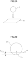
- a technique of coarse-view in which a particle group 11 including multiple particles illustrated in FIG. 1A is treated as a coarse-view particle 21 which is a single large particle, as illustrated in FIG. 2A , is required.
- the inventors of the present invention investigated a method of determining a parameter related to the coarse-view particle.
- a model was used in which a particle group 11 including multiple particles before being coarsely viewed, which is illustrated in FIG. 1A collided with a wall surface 12 and in which the coarse-view particle 21 illustrated in FIG. 2A collided with the wall surface 12.
- the following description describes a method of determining the parameter of the coarse-view particle by using the case where there is collision between the wall surface and one particle. However, description regarding a case where when particles collide with each other will be omitted because the description is substantially the same.
- a particle group 11 including multiple particles is arranged in a cubic shape with two particles each in a vertical direction, a horizontal direction, and a height direction, for a total of 2 3 particles.
- the number of particles arranged in one side direction i.e., 2 is used as a coarse-view magnification.
- FIG. 1B is a side view when the particle group 11 collides with the wall surface 12.
- the magnitude of the force applied to the particle group 11 can be expressed by the following Formula (1)
- m denotes the mass of each particle 11A and 11B
- a G denotes the acceleration of a center of gravity of the particle group 11
- ⁇ w denotes the viscosity coefficient calculated from the restitution between the wall surface 12 or the external particle and the particle 11A.
- the contact force between the particles is eliminated due to the law of action-reaction, so that the force F p received by the particle 11B, which is not in direct contact with the wall surface 12, from the adjacent particle 11A will not appear in Formula (1).
- [Math 1] ⁇ 3 m a G ⁇ 2 F w ⁇ ⁇ 2 ⁇ w ⁇ ⁇ w
- the particle group 11 including eight particles illustrated in FIG. 1A is assumed to be a single coarse-view particle 21.
- the force that the coarse-view particle 21 receives can be expressed by the following Formula (2).
- F cw denotes the force that the coarse-view particle 21 receives from the wall surface 12 or the external particle
- ⁇ cw denotes the amount of overlap of the coarse-view particle 21 with the wall surface 12 or with the external particle
- ⁇ cw denotes the viscosity coefficient calculated from the restitution between the coarse-view particle 21 and the wall surface 12 or the external particle, as illustrated in FIG. 2B.
- FIG. 2B is a side view when the coarse-view particle 21 collides with the wall surface 12.
- [Math 3] ⁇ 3 m a G F Cw ⁇ ⁇ Cw ⁇ ⁇ Cw
- the calculated result for the coarse-view particle 21 is consistent with the calculated result for the particle group 11 before the coarse-view particle 21 is coarsely viewed.
- Formula (3) and Formula (4) are derived from Formula (1) calculated for the particle group 11 and Formula (2) calculated for the coarse-view particle 21.
- Formula (3) and Formula (4) indicate that the corresponding parameters match.
- [Math 5] ⁇ Cw ⁇ ⁇ Cw ⁇ 2 ⁇ w ⁇ ⁇ w
- the force applied to each particle can be expressed as the following Formula (5) to Formula (7) using the amount of overlap ⁇ w , ⁇ p , and ⁇ cw of the particle.
- K w denotes the spring coefficient between the particle 11A and the wall surface 12 or the external particle
- K p denotes the spring coefficient between the internal particle of the particle group 11
- K cw denotes the spring coefficient between the coarse-view particle 21 and the wall surface 12 or the external particle.
- Formula (8) can be expressed as in Formula (10) below.
- K r def K cw ⁇ 2 K w
- ⁇ w K r 2 3 ⁇ cw
- the amount of overlap of the particles constituting the particle group 11 before being coarsely viewed can be calculated from the amount of overlap ⁇ CW of the coarse-view particle 21 and the wall surface 12 or the external particle.
- K r can be calculated by the characteristic equation using the relationship between the elastic energy of the particle group 11 before being coarsely viewed during the collision and the elastic energy of the coarse-view particle 21. Specifically, for example, a characteristic equation can be created to calculate K r on the assumption that the elastic energy of the entire particle group 11 before being coarsely viewed is equal to the elastic energy of the entire coarse-view particle.
- the elastic energy of the particle group 11 and the coarse-view particle colliding with the wall surface 12 can be calculated by integrating Formula (5) to Formula (7), which express the force applied to the particles 11A and 11B constituting the particle group 11 and the force applied to the coarse-view particle, at the distance of the amount of overlap.
- Formula (13) is a characteristic equation of K r in the vertical direction. Further, as it is clear from the defining equation of Formula (9), K r is a parameter related to the amount of overlap between the coarse-view particle and the particle constituting the particle group 11 before being coarsely viewed and is a parameter controlling the behavior of the coarse-view particle. Therefore, by obtaining K r in advance by the characteristic equation, it becomes possible to calculate a parameter with respect to the coarse-view particle, such as calculating the amount of overlap of a particle group before being coarsely viewed from the amount of overlap of the coarse-view particle, and to calculate the behavior of the coarse-view particle.
- the aforementioned K r can also be used to determine the thermal conductivity, which is a parameter related to the heat transfer of the coarse-view particle.
- the heat transfer of the particle is described by the following Formula (20) and Formula (21) by using the thermal conductivity.
- the contact radius depends on the amount of overlap of each particle. Further, as described above, the amount of overlap before and after the coarse-view is related to the solution of the characteristic equation in the vertical direction. Therefore, when the heat transfer equation is rewritten by using the solution K r of the characteristic equation in the vertical direction, the following Formula (22) and Formula (23) are obtained.
- a' denotes the contact radius of the coarse-view particle and r denotes the radius of the particle constituting the particle group 11.
- Q ⁇ 2 h ⁇ T
- Q c denotes the heat flow rate of the coarse-view particle
- h c denotes the heat flow coefficient of the coarse-view particle
- ⁇ T c denotes the temperature difference between the coarse-view particle 21 and the wall surface 12 or the external particle
- K' w denotes the thermal conductivity between the wall surface 12 and the coarse-view particle 21
- K' p denotes the thermal conductivity between the external particle and the coarse-view particle.
- the heat flow rate given to the particle group before being coarsely viewed and the heat flow rate given to the particle after being coarsely viewed can be made the same.
- the time change of temperature can be made to match before and after coarse-view.
- thermal conductivity before and after the coarse-view is explained here as an example, parameters other than the thermal conductivity can be calculated similarly after being coarsely viewed, by using the solution K r of the aforementioned characteristic equation.
- the coefficient of restitution, the coefficient of friction and the coefficient of rolling friction can be calculated using a characteristic equation. Further, depending on the model used in the calculation, these coefficients are adjustable and can be calculated and converted using the characteristic equation as described above.
- the simulation device of the present embodiment is a simulation device for analyzing the behavior of a granular material including multiple particles and can have the following members.
- a first parameter acquisition unit acquires a first parameter including a parameter related to a granular material.
- a second parameter calculation unit calculates a second parameter, which is a parameter for a coarse-view particle, when a particle group including multiple particles is coarsely viewed to form a single coarse-view particle.
- a coarse-view particle behavior analysis unit analyzes the behavior of the coarse-view particle based on the first parameter and the second parameter.
- the second parameter calculation unit calculates the second parameter by using a solution of the characteristic equation that uses a relationship between an elastic energy of the particle group and an elastic energy of the coarse-view particle.
- a simulation device 30 of the present embodiment includes an information processing unit (computer), and can be physically configured as a computer system including a Central Processing Unit (processor) (CPU) 31 as an arithmetic processing unit, a Random Access Memory (RAM) 32 or a Read-only Memory (ROM) 33 as a main storage device, an auxiliary storage device 34, an input/output interface 35, and a display device 36 as an output device. These are interconnected by a bus 37.
- the auxiliary storage device 34 and the display device 36 may be provided externally.
- the CPU 31 controls the overall operation of the simulation device 30 and performs various kinds of information processing.
- the CPU 31 can calculate the second parameter, which is a parameter for the coarse-view particle, and analyze the behavior of the coarse-view particle by executing, for example, a simulation method described later or a program (simulation program) stored in the ROM 33 or the auxiliary storage device 34.
- the RAM 32 is used as a work area for the CPU 31 and may include a nonvolatile RAM that stores key control parameters and information.
- the ROM 33 can store a program (simulation program) or the like.
- the auxiliary storage device 34 is a storage device such as a Solid State Drive (SSD) or a Hard Disk Drive (HDD) and can store various data, files, or the like, necessary for the operation of the simulation device.
- SSD Solid State Drive
- HDD Hard Disk Drive
- the input/output interface 35 includes both a user interface such as a touch panel, keyboard, display screen, and operation buttons, and a communication interface that takes in information from an external data storage server and outputs analysis information to other electronic devices.
- a user interface such as a touch panel, keyboard, display screen, and operation buttons
- a communication interface that takes in information from an external data storage server and outputs analysis information to other electronic devices.
- the display device 36 is a monitor display or the like. In the display device 36, an analysis screen is displayed, and the screen is updated according to input/output operations via the input/output interface 35.
- Each function of the simulation device 30 illustrated in FIG. 3 can be implemented by reading a program (simulation program) or the like from a main storage device such as RAM 32 or ROM 33 or an auxiliary storage device 34 and executing it by the CPU 31, thereby reading and writing data from and to the RAM 32 or the like, and operating the input/output interface 35 and the display device 36.
- a program simulation program
- main storage device such as RAM 32 or ROM 33 or an auxiliary storage device 34
- FIG. 4 illustrates a functional block diagram of the simulation device 30 of the present embodiment.
- the simulation device 30 may include a reception unit 41, a processing device 42, and an output unit 43.
- Each of these parts is an information processing device such as a personal computer provided with a CPU, a storage device, and various interfaces of the simulation device 30, and is realized in cooperation with software and hardware by executing, for example, a simulation method and a program which will be described later in which the CPU is stored in advance.
- the reception unit 41 receives input of commands and data from a user related to the processing executed by the processing device 42.
- the reception unit 41 includes a keyboard or a mouse for operated by a user and inputting a command or the like, a communication device for inputting the command or the like through a network, and a reading device for inputting the command or the like from various storage media such as a CD-ROM or a DVD-ROM.
- the processing device 42 may include a first parameter acquisition unit 421, a second parameter calculation unit 422, and a coarse-view particle behavior analysis unit 423. It should be noted that the processing device may include further optional members as needed, for example, an initial setting unit or the like.
- a first parameter including a parameter related to a granular material to be analyzed can be acquired.
- the first parameter may include various parameters required for the analysis in addition to the parameter associated with the granular material. Since the first parameter can be selected depending on the content of the analysis (simulation), the specific type is not particularly limited.
- the first parameter includes various parameters required for the discrete element method calculation, specifically one or more parameters selected from, for example, particle size, particle number, Young's modulus, time step of calculation, Poisson's ratio, friction coefficient with wall surface, friction coefficient between particles, rolling friction coefficient, density, and the like.
- the first parameter may be data stored in a database or the like, or an experimental value obtained by performing an experiment in advance. Further, the first parameter may be a calculated value obtained by fitting the experimental results by simulation or the like.
- a particle group including multiple particles in the granular material can be coarsely viewed into a single coarse-view particle and the calculation can be performed with a smaller number of particles.
- the coarse-view particle differs in various parameters such as mass from the individual particles constituting the particle group before being coarsely viewed. Therefore, it is necessary to calculate and set the parameters required for the calculation of the coarse-view particle.
- the second parameter can be calculated using K r , which is the solution of the characteristic equation derived using the relationship between the elastic energy of the particle group before being coarsely viewed and the elastic energy of the coarse-view particle.
- K r is the solution of the characteristic equation derived using the relationship between the elastic energy of the particle group before being coarsely viewed and the elastic energy of the coarse-view particle.
- the aforementioned characteristic equation of K r in the vertical direction i.e., Formula (13)
- K r in the vertical direction can be calculated from Formula (13).
- the second parameter can be calculated by using K r in the vertical direction, which is the solution of the characteristic equation, in Formula (13). Further, K r in the tangential direction can be calculated by using the characteristic equation of K r in the tangential direction in Formula (19), and the second parameter can be calculated using such K r in the tangential direction.
- K r is a parameter that controls the behavior of the coarse-view particle, and by using K r , various parameters related to the behavior of the coarse-view particle can be calculated.
- the type of the second parameter used in the coarse-view particle behavior analysis unit described later is not particularly limited because the type of the second parameter can be selected according to the content of the analysis.
- the second parameter may also include the thermal conductivity of the coarse-view particle.
- the second parameter calculation unit can calculate the thermal conductivity using the solution K r of the aforementioned characteristic equation.
- the behavior of the coarse-view particle can be analyzed using the first parameter acquired by the first parameter acquisition unit 421 and the second parameter calculated by the second parameter calculation unit 422. Specifically, the behavior of the coarse-view particle can be analyzed using the discrete element method. The behavior of the granular material can be analyzed by analyzing the behavior of the coarse-view particle.
- the behavior here includes not only the change in position due to the motion of the coarse-view particle, but also the state change such as temperature change.
- An initial setting unit (not illustrated) can initialize the position of the particles constituting the granular material to be analyzed, and set conditions for analysis, such as the temperature of the area where the granular material is to be placed, if necessary. For example, in a case where the initial conditions are set in advance in a program or the like used for analyzing the behavior of the coarse-view particle in the coarse-view particle behavior analysis unit 423, or in a case where the data is acquired by the first parameter acquisition unit 421, the initial setting unit may be omitted.
- the output unit 43 may include a display or the like.
- the simulation result obtained by the coarse-view particle behavior analysis unit 423 can be output to the output unit 43.
- the content of the simulation result to be output is not particularly limited, but for example, the position of the coarse-view particle can be output to the output unit 43 as an image in time series and displayed. Further, for example, a time series change of the temperature distribution of the granular material can be output to the output unit 43 as an image and displayed.
- the simulation device of the present embodiment it is possible to simulate the behavior of a granular material including multiple particles, and the use thereof is not particularly limited.
- it can be suitably used to simulate the behavior of the granular material in a rotating body such as a kiln. That is, the simulation device of the present embodiment can also analyze the behavior of the granular material in the rotating body.
- the amount of calculation can be reduced by making a particle group including multiple particles into a single coarse-view particle. Therefore, it is possible to reduce the amount of calculation and efficiently calculate the behavior of the granular material on a large scale, such as that of a plant used in a factory.
- the parameter of the coarse-view particle is calculated by using the aforementioned parameter K r , the calculation can be performed with high accuracy.
- the simulation device of the present embodiment may further include a granular material supply device, a reaction furnace, a controller, or the like, to perform various manufacturing processes using the granular material by using the simulation results.
- the granular material supply device includes a device such as a hopper that can store and discharge granular material.
- the granular material supply device may further have a feeder, a valve, or other supply controller to control the amount of granular material discharged and supplied from the hopper or the like to the reaction furnace. Based on the simulation results, it is preferable to include multiple granular material supply devices each containing granular materials of different physical properties, such as granular materials of a desired average particle size.
- reaction furnace examples include various reaction furnaces such as heating furnaces, and rotary furnaces such as kilns.
- the granular material supply device and the reaction furnace can be connected by piping.
- the controller can control to provide the granular material to the reaction furnace with the desired physical properties, for example, the desired average particle size, based on the obtained results of the behavior of the granular material in the reaction furnace.
- the controller can also control the heating conditions of the reaction furnace based on the obtained results of the behavior of the granular material in the reaction furnace. Examples of heating conditions include temperature conditions in the reaction furnace, atmospheric conditions, and heating time. Further, various sensors may be provided in the granular material supply device or the reaction furnace to detect the amount of granular material to be supplied, the temperature, and the like, and the measurement results measured at any time may be supplied to the controller. In this case, the controller may control each device based on the obtained measurement data.
- the controller may include a CPU, a main storage device, an auxiliary storage device, an input/output interface, and the like, so that the controller can perform data processing such as control conditions and communicate with the granular material supply device and the reaction furnace.
- the main storage device may include a RAM and a ROM
- the auxiliary storage device may include an SSD and an HDD.
- the input/output interface may include a communication interface for exchanging control signals and data with the granular material supply device or the reaction furnace.
- a type of the communication interface is not particularly limited. Both wired and wireless communication methods can be used, for example, a wired local area network (LAN) or a wireless LAN.
- the granular material of the desired physical properties can be supplied from the granular material supply device and further heated in the reaction furnace under the prescribed heating conditions to increase the reaction rate of the granular material. Further, since the heating conditions can be optimized, the amount of energy used during the reaction can be optimized to improve productivity.
- the simulation device of the present embodiment includes the above granular material supply device or the like, the simulation device can also be called a reactor or the like. Further, the granular material supply device, the reaction furnace, and the controller can be detachable from the unit for analyzing a behavior of a granular material including multiple particles, and the simulation results can be reflected in the controller and then used separately.
- the simulation method of the present embodiment can be performed using, for example, the aforementioned simulation device. Therefore, the explanation shall be omitted for some of the matters already explained.
- the simulation method of the present embodiment relates to a simulation method of analyzing a behavior of a granular material including multiple particles.
- the simulation method of the present embodiment can be performed according to the flow diagram illustrated in FIG. 5 and may include the following processes.
- the simulation method of the present embodiment may include a first parameter acquisition process (S1) for acquiring a first parameter including a parameter related to a granular material; a second parameter calculation process (S2) for calculating a second parameter, which is a parameter for a coarse-view particle, when a particle group including multiple particles is coarsely viewed to form a single coarse-view particle; a coarse-view particle behavior analysis process (S3) for analyzing a behavior of the coarse-view particle based on the first parameter and the second parameter.
- the second parameter can be calculated by using a solution of a characteristic equation using a relationship between an elastic energy of the particle group and an elastic energy of the coarse-view particle.
- a first parameter including a parameter related to a granular material to be analyzed can be acquired.
- the first parameter acquisition process can be performed in the first parameter acquisition unit 421.
- the first parameter can be selected depending on the content of the analysis, the specific type is not particularly limited.
- the first parameter may be various parameters required for the discrete element method calculation. Because a specific example of the first parameter has already been described with respect to the simulation device, the description will be omitted here.
- the first parameter may be data stored in a database or the like, or may be an experimental value obtained by performing an experiment in advance. Further, the first parameter may be a calculated value obtained by fitting the experimental results by simulation or the like.
- a particle group including multiple particles in the granular material can be coarsely viewed into a single coarse-view particle, and the number of particles can be reduced to perform the calculation.
- the second parameter can be calculated using K r , which is the solution of the characteristic equation derived using the relationship between the elastic energy of the particle group before being coarsely viewed and the elastic energy of the coarse-view particle.
- K r is the solution of the characteristic equation derived using the relationship between the elastic energy of the particle group before being coarsely viewed and the elastic energy of the coarse-view particle.
- the aforementioned characteristic equation of K r in the vertical direction i.e., Formula (13)
- K r in the vertical direction can be calculated from Formula (13).
- the second parameter can be calculated by using K r in the vertical direction, which is the solution of the characteristic equation in Formula (13). Further, K r in the tangential direction can be calculated by using the characteristic equation of K r in the tangential direction in Formula (19), and the second parameter can be calculated using such K r in the tangential direction.
- K r is a parameter that controls the behavior of the coarse-view particle, and by using K r , various parameters related to the behavior of the coarse-view particle can be calculated.
- the second parameter calculation process can be performed in the second parameter calculation unit 422, for example.
- the type of the second parameter used in the coarse-view particle behavior analysis process described later is not particularly limited because the type of the second parameter can be selected according to the content of the analysis.
- the second parameter can also include the thermal conductivity of the coarse-view particle.
- the second parameter calculation process can calculate the thermal conductivity using the solution K r of the aforementioned characteristic equation.
- the behavior of the coarse-view particle can be analyzed using the first parameter acquired in the first parameter acquisition process (S1) and the second parameter calculated in the second parameter calculation process (S2). Specifically, the behavior of the coarse-view particle can be analyzed using the discrete element method. The behavior of the granular material can be analyzed by analyzing the behavior of the coarse-view particle.
- the behavior here includes not only the change in position due to the motion of the coarse-view particle, but also the state change such as temperature change.
- the simulation method of the present embodiment may also include, for example, an initial setting process.
- the initial setting process can initialize the position of the particles constituting the granular material to be analyzed, and set conditions for analysis, such as the temperature of the area where the granular material is to be placed, if necessary.
- the initial setting process may be omitted.
- the simulation method of the present embodiment may also include an output process, for example.
- the output process for example, the simulation result obtained by the coarse-view particle behavior analysis process (S3) can be output to the output unit.
- the content of the simulation result to be output is not particularly limited, but for example, the position of the coarse-view particle can be output as an image in time series and displayed. Further, for example, a time series change of the temperature distribution of the granular material can be output to the output unit as an image and displayed.
- the amount of calculation can be reduced by making a particle group including multiple particles into a single coarse-view particle. Therefore, it is possible to reduce the amount of calculation and efficiently calculate the behavior of the granular material on a large scale, such as that of a plant used in a factory.
- the parameter of the coarse-view particle is calculated by using the aforementioned parameter K r , the calculation can be performed with high accuracy.
- the simulation method of the present embodiment may further include a granular material supply process, a reaction process, or the like, to perform various manufacturing processes using the granular material by using the simulation results.
- a granular material can be supplied from the granular material supply device to the reaction furnace based on a result of a behavior of the granular material in the reaction furnace obtained by simulation.
- the granular material of a specified physical property selected based on the simulation result can be supplied as the granular material.
- the granular material supplied to the reaction furnace in the granular material supply process can be heated.
- the granular material can be heated under prescribed heating conditions based on the simulation result.
- the granular material of the desired physical properties can be supplied from the granular material supply device and further heated in the reaction furnace under the prescribed heating conditions to increase the reaction rate of the granular material. Further, since the heating conditions can be optimized, the amount of energy used during the reaction can be optimized to improve productivity.
- the simulation method of the present embodiment performs the above granular material supply process or the like
- the simulation method may also be a granular material processing method or the like.
- the program of the present embodiment relates to a program for analyzing a behavior of a granular material including multiple particles, and the computer can function as the following parts.
- a first parameter acquisition unit acquires a first parameter including a parameter related to the granular material.
- a second parameter calculation unit calculates a second parameter, which is a parameter for a coarse-view particle, when a particle group including multiple particles is coarsely viewed to form a single coarse-view particle.
- a coarse-view particle behavior analysis unit analyzes a behavior of the coarse-view particle based on the first parameter and the second parameter.
- the second parameter calculation unit calculates the second parameter by using a solution of the characteristic equation that uses a relationship between an elastic energy of the particle group and an elastic energy of the coarse-view particle.
- the second parameter may also include the thermal conductivity of the coarse-view particles.
- the second parameter calculation unit can calculate the thermal conductivity using the solution of the aforementioned characteristic equation.
- the program according to the present embodiment can be stored in various storage media of the main storage device or the auxiliary storage device such as the RAM or ROM of the simulation device described above.
- the program can be read and executed by the CPU to read and write data in the RAM or the like, and the input/output interface and the display device can be operated. For this reason, the description of the matters already described in the simulation device is omitted.
- the program of the present embodiment described above may be provided by storing it on a computer connected to a network such as the Internet and downloading it via the network.
- the program of the present embodiment may be provided and distributed via a network such as the Internet.
- the program of the present embodiment may be distributed or distributed while stored in an optical disk such as a CD-ROM or a recording medium such as a semiconductor memory.
- the amount of calculation can be reduced by making a particle group including multiple particles into a single coarse-view particle. Therefore, it is possible to reduce the amount of calculation and efficiently calculate the behavior of the granular material on a large scale, such as that of a plant used in a factory.
- the parameter of the coarse-view particle is calculated by using the aforementioned parameter K r , the calculation can be performed with high accuracy.
- the point of assuming that the angular momentum and rotational energy coincide before and after coarse-view differs from that of the first embodiment described above.
- the torque can be calculated using the amount of overlap obtained as described above. This enables the behavior of the particles after coarse-view to be analyzed more accurately while reducing the amount of calculation.
- the amount of overlap in the tangential direction is obtained by using the time integral of the tangential component v t (indicated by an arrow above v t in the formula below) of the velocity from the start of the contact to the end of the contact.
- v t is the time
- the vector r is the vector from the center of the particles constituting the particle group 11 to the contact point
- the vector w is the rotation vector of the particle group 11.
- hat t in the following formula indicates the unit vector of overlap in the tangential direction.
- each amount of overlap between the particle and the wall surface is expressed by the following Formula (29).
- the subscript t in the following formula means the tangential component.
- the amount of overlap of the coarse-view particle 21 is expressed by the following Formula (31).
- the vector ⁇ cw (indicated by the arrow above ⁇ cw in the following formula) is the rotation vector of the coarse-view particle 21.
- ⁇ cw , t t ⁇ ⁇ start end v c w , t ⁇ + ⁇ c w ⁇ ⁇ ⁇ r ⁇ dt
- the first and second terms on the right-hand side denote the rotational motion component (Spin) and the orbital motion component (Orbit) of the particle group before being coarsely viewed, respectively.
- the vectors ⁇ cw , ⁇ s , and ⁇ o denote the angular velocity of the coarse-view particle, the angular velocity of the rotational motion of the particle group before being coarsely viewed, and the angular velocity of the orbital motion of the particle group before being coarsely viewed, respectively.
- I cw , I s and I o denote the moment of inertia of the coarse-view particle, the moment of inertia of the rotational motion of the particle group before being coarsely viewed, and the moment of inertia of the orbital motion of the particle group before being coarsely viewed.
- Formula (33), Formula (34), and Formula (35) are used for simplification of calculation, but there are several possible types depending on the shape of the coarse-view particle. For example, an attempt to calculate the moment of inertia by considering the shape factor of the coarse-view particle in the cubic shape yields the following Formula (38) to Formula (41).
- the tangential force can be calculated from the amount of overlap in the tangential direction described so far to calculate the torque.
- the rolling friction between each particle and between the particle and the wall surface generates a torque proportional to the product of the vertical drag on the particle and the contact radius. Since each rolling friction is generated in each particle, the rolling friction resistance across the coarse-view particle can be expressed by the following Formula (44).
- the vector T tot_fric denotes the rolling friction resistance of the entire coarse-view particle
- the vector T w,fric denotes the rolling friction resistance between the particle group 11 and the wall surface 12 or the external particle
- the vector T p,fric represents the rolling friction resistance between internal particles of particle group 11.
- Each vector is represented by an arrow above the letter in the formula below. Note that in the particle group 11, the vector T p,fric is doubled, as illustrated in Formula (44), because the opposite contact force is exerted by the action-reaction between particles.
- T w,fric and T p,fric are represented by Formula (45) and Formula (46). Note that hat w in the formula denotes a unit vector in the direction of rotation.
- T tot _ fric ⁇ T w , fric ⁇ + 2 T p , fric ⁇
- T w , fric ⁇ ⁇ ⁇ w ⁇ 2 F w r w , cont ⁇ ⁇
- T p , fric ⁇ ⁇ ⁇ p ⁇ 2 ⁇ ⁇ 1 F p r p , cont ⁇ ⁇
- the contact radius r w and r p in Formula (45) and Formula (46) can be geometrically calculated from the amount of overlap, and the accuracy can be enhanced by using the amount of overlap calculated based on the previously described definition of the equation of motion in the tangential direction.
- ⁇ w denotes the rolling friction coefficient of the particle group 11 with the wall surface 12 or with the external particle
- ⁇ p denotes the rolling friction coefficient of the internal particles of the particle group 11.
- the second parameter calculation unit can calculate the second parameter by using the solution of the characteristic equation using the relationship between the elastic energy of the particle group and the elastic energy of the coarse-view particle.
- the equation of motion in the tangential direction it is possible to calculate the amount of overlap by assuming that the angular momentum and rotational energy coincide before and after coarse-view.
- the amount of overlap calculated in the case of the equation of motion in the tangential direction being used can be used.
- the second parameter can be calculated by using the solution of the characteristic equation derived using the relationship between the elastic energy of the particle group before being coarsely viewed and the elastic energy of the coarse-view particle.
- the equation of motion in the tangential direction it is possible to calculate the amount of overlap by assuming that the angular momentum and rotational energy coincide before and after coarse-view.
- the amount of overlap calculated in the case of the equation of motion in the tangential direction being used can be used.
- the second parameter calculation unit can calculate the second parameter by using the solution of the characteristic equation using the relationship between the elastic energy of the particle group and the elastic energy of the coarse-view particle.
- the equation of motion in the tangential direction it is possible to calculate the amount of overlap by assuming that the angular momentum and rotational energy coincide before and after coarse-view.
- the amount of overlap calculated in the case of the equation of motion in the tangential direction being used can be used.
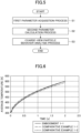
- the temperature change of the granular material layer filled in a rectangular container was analyzed by the discrete element method calculation when heating was performed from the bottom using the parameters illustrated in Table 1.
- the change in the average temperature of the granular material layer in the container obtained by the analysis is illustrated in FIG. 6 .
- the coefficient of restitution was 0.1
- the coefficient of friction was 0.7
- the coefficient of rolling friction was 0.001.
- EMBODIMENT 1-1 COMPARATIVE EXAMPLE 1-1 COMPARATIVE EXAMPLE 1-2 PARTICLE SIZE 4 mm 2 mm 4 mm PARTICLE-PARTICLE THERMAL CONDUCTIVITY 1107 W/m 1000 W/m 1000 W/m PARTICLE-WALL THERMAL CONDUCTIVITY 1196 W/m 1000 W/m 1000 W/m INITIAL TEMPERATURE 300 K 300 K 300 K YOUNG'S MODULUS 2.5 ⁇ 10 6 Pa POISSON'S RATIO 0.25
- the temperature change of the granular material layer filled in the rectangular container was analyzed under the same conditions as in Comparative Example 1-1 except that the coarse-view magnification ⁇ was set at 2 and the particle group including 8 particles was made into a single coarse-view particle. Although the particle size was changed as illustrated in Table 1 because the coarse-view particle was used, the analysis was performed using the same parameters as in Comparative Example 1-1 except for the particle size.
- the change in the average temperature of the granular material layer in the container obtained by the analysis is illustrated in FIG. 6 .
- the temperature change of the granular material layer filled in the rectangular container was analyzed using the simulation device described above, with the coarse-view magnification ⁇ set at 2.
- the first parameter including a parameter related to the granular material to be analyzed was acquired by the first parameter acquisition unit 421 (i.e., the first parameter acquisition process S1).
- the second parameter calculation unit 422 calculated the second parameter, which is a parameter for the coarse-view particle (i.e., the second parameter calculation process S2).
- the thermal conductivity for the coarse-view particle was calculated by Formula (26) and Formula (27) by using the parameter K r , which is the solution of the characteristic equation illustrated in Formula (13) and Formula (19) above.
- the coefficient of restitution, the coefficient of friction, and the coefficient of rolling friction were calculated by using the characteristic equation. As described above, depending on the model applied to the calculation, these coefficients are adjustable and can be calculated and converted by using the characteristic equation as described above.
- the calculated parameter K r is illustrated in Table 2. [Table 2] Kr VERTICAL DIRECTION PARTICLE-PARTICLE 0.4805 PARTICLE-WALL 0.6057 TANGENTIAL DIRECTION PARTICLE-PARTICLE 0.6135 PARTICLE-WALL 0.7159
- the obtained, calculated first parameter and second parameter are illustrated in Table 1.
- the behavior of the coarse-view particle specifically the temperature change, was analyzed in the coarse-view particle behavior analysis unit 423 (i.e., the coarse-view particle behavior analysis process S3).
- the results are illustrated in FIG. 6 .
- Embodiment 1-1 is almost identical to the result of Comparative Example 1-1, which did not perform coarse-view, and it can be checked that the parameters of the coarse-view particle were appropriately selected, set, and analyzed.
- the number of particles is 1/8 times larger than in Comparative Example 1-1 because of the coarse-view, and the amount of calculation can be reduced compared to Comparative Example 1-1.
- the coefficient of restitution was 0.75
- the coefficient of friction was 0.3
- the coefficient of rolling friction was 0.5.
- the movement of granular material in the kiln obtained by the analysis is illustrated in FIG. 8A to 8D
- the temperature distribution of the granular material in the kiln obtained by the analysis is illustrated in FIG. 11A to 11C
- the average temperature of the granular material (particles) in the kiln obtained by the analysis is illustrated in FIG. 13 .
- FIG. 8A illustrates the state before a kiln 70 begins to rotate, with the grouped first granular material group 71 and the second granular material group 72 half each.
- FIG. 8B , 8C, and 8D illustrate the state of the kiln at 2 seconds, 4 seconds, and 6 seconds after the start of the rotation, respectively, and illustrate the state in which the first granular material group 71 and the second granular material group 72 are mixed.
- FIG. 11A illustrates the state before the kiln 70 begins to rotate, it can be checked that the temperature is within the first temperature region 101 and is uniform.
- FIG. 11B and 11C illustrate the state of the kiln 3 seconds after the start of rotation and 6 seconds after the start of the rotation, respectively. Since the kiln 70 is heated from the outer wall side of the kiln 70, it can be confirmed that the first temperature region 101, the second temperature region 102, and the third temperature region 103 are distributed in order from the center side of the granular material. The temperature increases in the order of the first temperature region 101, the second temperature region 102, and the third temperature region 103.
- EMBODIMENT 2-1 COMPARATIVE EXAMPLE 2-1 COMPARATIVE EXAMPLE 2-2 PARTICLE SIZE 8 mm 2 mm 8 mm PARTICLE-PARTICLE THERMAL CONDUCTIVITY 1176 W/m 1000 W/m 1000 W/m PARTICLE-WALL THERMAL CONDUCTIVITY 1350 W/m 1000 W/m 1000 W/m WALL TEMPERATURE 1000 K NUMBER OF ROTATIONS 10 rpm YOUNG'S MODULUS 2.5 ⁇ 10 6 Pa POISSON'S RATIO 0.25
- the movement of granular material in the kiln determined by the analysis is illustrated in FIG. 9A to 9D
- the temperature distribution of granular material in the kiln determined by the analysis is illustrated in FIG. 12A to 12C
- the average temperature of granular material in the kiln determined by the analysis is illustrated in FIG. 13 .
- FIG. 9A illustrates the state before the kiln 70 begins to rotate, with the grouped first granular material group 71 and the second granular material group 72 half each.
- FIG. 9B, 9C, and 9D illustrate the state of the kiln at 2 seconds, 4 seconds, and 6 seconds after the start of the rotation, respectively, and illustrate the state in which the first granular material group 71 and the second granular material group 72 are mixed.
- FIG. 12A illustrates the state before the kiln 70 begins to rotate, it can be checked that the temperature is within the first temperature region 101 and is uniform.
- FIG. 12B and 12C illustrate the state of the kiln 3 seconds after the start of rotation and 6 seconds after the start of the rotation, respectively. Since the kiln 70 is heated from the outer wall side of the kiln 70, it can be confirmed that the first temperature region 101, the second temperature region 102, and the third temperature region 103 are distributed in order from the center side of the granular material. The temperature increases in the order of the first temperature region 101, the second temperature region 102, and the third temperature region 103.
- the first parameter including a parameter related to the granular material to be analyzed was acquired by the first parameter acquisition unit 421 (i.e., the first parameter acquisition process S1).
- the second parameter calculation unit 422 calculated the second parameter, which is a parameter for the coarse-view particle (i.e., the second parameter calculation process S2).
- the thermal conductivity for the coarse-view particle was calculated by Formula (26) and Formula (27) by using the parameter K r , which is the solution of the characteristic equation illustrated in Formula (13) and Formula (19) above.
- the coefficient of restitution, the coefficient of friction, and the coefficient of rolling friction were calculated by using the characteristic equation.
- the calculated parameter K r is illustrated in Table 4. [Table 4] Kr VERTICAL DIRECTION PARTICLE-PARTICLE 0.2036 PARTICLE-WALL 0.3084 TANGENTIAL DIRECTION PARTICLE-PARTICLE 0.3460 PARTICLE-WALL 0.4565
- the obtained, calculated first parameter and second parameter are illustrated in Table 3.
- the behavior of the coarse-view particle was analyzed in the coarse-view particle behavior analysis unit 423 (i.e., the coarse-view particle behavior analysis step S3).
- the movement of the granular material in the kiln obtained by analysis is illustrated in FIG. 7A to 7D
- the temperature distribution of granular material in the kiln obtained by analysis is illustrated in FIG. 10A to 10C
- the average temperature of granular material in the kiln obtained by analysis is illustrated in FIG. 13 .
- FIG. 7A illustrates the state before the kiln 70 begins to rotate, with the grouped first granular material group 71 and the second granular material group 72 half each.
- FIG. 7B, 7C , and 7D illustrate the state of the kiln at 2 seconds, 4 seconds, and 6 seconds after the start of the rotation, respectively, and illustrate the state in which the first granular material group 71 and the second granular material group 72 are mixed.
- FIG. 10A illustrates the state before the kiln 70 begins to rotate, it can be checked that the temperature is within the first temperature region 101 and is uniform.
- FIG. 10B and 10C illustrate the state of the kiln 3 seconds after the start of rotation and 6 seconds after the start of the rotation, respectively. Since the kiln 70 is heated from the outer wall side of the kiln 70, it can be confirmed that the first temperature region 101, the second temperature region 102, and the third temperature region 103 are distributed in order from the center side of the granular material. The temperature increases in the order of the first temperature region 101, the second temperature region 102, and the third temperature region 103.
- Embodiment 2-1 is almost identical to the result of Comparative Example 2-1, which did not perform coarse-view, and it can be checked that the parameters of the coarse-view particle were appropriately selected, set, and analyzed.
- Embodiment 2-1 and Comparative Example 2-1 had similar tendencies such as having an inflection point.
- Embodiment 2-1 the number of particles is 1/64 times larger than in Comparative Example 2-1 because of the coarse-view, and the amount of calculation can be reduced compared to Comparative Example 2-1.
Landscapes
- Engineering & Computer Science (AREA)
- Chemical & Material Sciences (AREA)
- Theoretical Computer Science (AREA)
- Life Sciences & Earth Sciences (AREA)
- Computing Systems (AREA)
- Bioinformatics & Computational Biology (AREA)
- Bioinformatics & Cheminformatics (AREA)
- Physics & Mathematics (AREA)
- General Health & Medical Sciences (AREA)
- Health & Medical Sciences (AREA)
- Crystallography & Structural Chemistry (AREA)
- General Physics & Mathematics (AREA)
- Immunology (AREA)
- Dispersion Chemistry (AREA)
- Analytical Chemistry (AREA)
- Biochemistry (AREA)
- Pathology (AREA)
- Medicinal Chemistry (AREA)
- Databases & Information Systems (AREA)
- Software Systems (AREA)
- Geometry (AREA)
- Evolutionary Computation (AREA)
- General Engineering & Computer Science (AREA)
- Computer Hardware Design (AREA)
- Management, Administration, Business Operations System, And Electronic Commerce (AREA)
Applications Claiming Priority (3)
| Application Number | Priority Date | Filing Date | Title |
|---|---|---|---|
| JP2020095620 | 2020-06-01 | ||
| JP2020162719A JP7101387B2 (ja) | 2020-06-01 | 2020-09-28 | シミュレーション装置、シミュレーション方法、プログラム |
| PCT/JP2021/020745 WO2021246378A1 (ja) | 2020-06-01 | 2021-05-31 | シミュレーション装置、シミュレーション方法、プログラム |
Publications (3)
| Publication Number | Publication Date |
|---|---|
| EP4160184A1 true EP4160184A1 (de) | 2023-04-05 |
| EP4160184A4 EP4160184A4 (de) | 2024-06-26 |
| EP4160184B1 EP4160184B1 (de) | 2025-07-02 |
Family
ID=78830357
Family Applications (1)
| Application Number | Title | Priority Date | Filing Date |
|---|---|---|---|
| EP21818068.5A Active EP4160184B1 (de) | 2020-06-01 | 2021-05-31 | Simulationsvorrichtung, simulationsverfahren und programm |
Country Status (5)
| Country | Link |
|---|---|
| US (1) | US11892388B2 (de) |
| EP (1) | EP4160184B1 (de) |
| KR (1) | KR102660215B1 (de) |
| CN (1) | CN115698672B (de) |
| WO (1) | WO2021246378A1 (de) |
Cited By (1)
| Publication number | Priority date | Publication date | Assignee | Title |
|---|---|---|---|---|
| CN119129075A (zh) * | 2024-09-20 | 2024-12-13 | 中国矿业大学(北京) | 一种用于分析锚杆拉伸承载特性的计算方法 |
Families Citing this family (1)
| Publication number | Priority date | Publication date | Assignee | Title |
|---|---|---|---|---|
| KR102660215B1 (ko) * | 2020-06-01 | 2024-04-23 | 스미토모 긴조쿠 고잔 가부시키가이샤 | 시뮬레이션 장치, 시뮬레이션 방법, 프로그램 |
Family Cites Families (37)
| Publication number | Priority date | Publication date | Assignee | Title |
|---|---|---|---|---|
| JP2000322407A (ja) * | 1999-05-12 | 2000-11-24 | Toyota Central Res & Dev Lab Inc | 流体中における媒体の運動解析方法 |
| EP1513622A4 (de) * | 2002-06-13 | 2005-09-14 | Univ Pennsylvania | Verfahren, systeme und rechnerprogrammprodukte zur simulation von biomembranen unter verwendendung von coarse-grain-modellen |
| US7813903B2 (en) * | 2005-04-13 | 2010-10-12 | Autodesk, Inc. | Fixed time step dynamical solver for interacting particle systems |
| CA2580998A1 (en) * | 2006-03-03 | 2007-09-03 | Queen's University At Kingston | Adaptive analysis methods |
| US7565276B2 (en) * | 2006-04-05 | 2009-07-21 | Seoul National University Industry Foundation | Method of simulating detailed movements of fluids using derivative particles |
| KR100984048B1 (ko) * | 2008-10-14 | 2010-09-30 | 한국전자통신연구원 | 파티클 유체 시뮬레이션에서의 강성체 상호작용 처리 방법 |
| JP2010108183A (ja) * | 2008-10-29 | 2010-05-13 | Ihi Corp | シミュレーション方法及びシミュレーション装置 |
| JP5527572B2 (ja) * | 2008-10-29 | 2014-06-18 | 株式会社Ihi | シミュレーション方法及びシミュレーション装置 |
| JP5241468B2 (ja) * | 2008-12-19 | 2013-07-17 | 住友重機械工業株式会社 | シミュレーション方法及びプログラム |
| US20100185420A1 (en) * | 2009-01-18 | 2010-07-22 | Ejiang Ding | Computer system for computing the motion of solid particles in fluid |
| KR20120087910A (ko) * | 2009-09-28 | 2012-08-07 | 아사히 가라스 가부시키가이샤 | 적층 유리 기판과 그의 제조 방법 및 상기 적층 유리 기판을 사용한 전자 디바이스 |
| JP2011081530A (ja) * | 2009-10-06 | 2011-04-21 | Univ Of Tokyo | 粒子モデルの離散要素法解析シミュレーション方法、離散要素法解析シミュレーションプログラム、及び離散要素法解析シミュレーション装置 |
| US20120150496A1 (en) * | 2010-12-09 | 2012-06-14 | Jiun-Der Yu | Simplified Fast 3D Finite Difference Particulate Flow Algorithms for Liquid Toner Mobility Simulations |
| JP5669589B2 (ja) * | 2011-01-19 | 2015-02-12 | 住友重機械工業株式会社 | 解析装置 |
| JP2013210918A (ja) * | 2012-03-30 | 2013-10-10 | Sumitomo Chemical Co Ltd | 粒子挙動シミュレーション装置、粒子挙動シミュレーション方法、制御プログラム、および記録媒体 |
| US9183676B2 (en) * | 2012-04-27 | 2015-11-10 | Microsoft Technology Licensing, Llc | Displaying a collision between real and virtual objects |
| JP6186675B2 (ja) * | 2012-07-05 | 2017-08-30 | 日本電気硝子株式会社 | ガラス樹脂積層体 |
| JP5930987B2 (ja) * | 2013-02-27 | 2016-06-08 | 住友重機械工業株式会社 | 解析装置およびコンピュータプログラム |
| US9824192B2 (en) * | 2013-04-04 | 2017-11-21 | Sumitomo Rubber Industries, Ltd. | Simulation method for macromolecular material |
| US20140358505A1 (en) * | 2013-05-31 | 2014-12-04 | The Board Of Trustees Of The University Of Illinois | Collision impulse derived discrete element contact force determination engine, method, software and system |
| US10210287B2 (en) * | 2013-12-31 | 2019-02-19 | Disney Enterprises, Inc. | Augmented material point method for simulating phase changes and varied materials |
| US10019827B2 (en) * | 2013-12-31 | 2018-07-10 | Disney Enterprises, Inc. | Material point method for simulation of granular materials |
| US10319132B2 (en) * | 2014-05-08 | 2019-06-11 | Nvidia Corporation | Method and system for representing objects with velocity-dependent particles |
| CN104636538B (zh) * | 2014-12-30 | 2018-06-19 | 广东工业大学 | 基于dem的球磨机颗粒轨迹分析与能耗建模方法 |
| US10423736B2 (en) * | 2015-08-28 | 2019-09-24 | University Of British Columbia | Methods and systems for simulating hydrodynamics in gas-solid fluidized beds |
| CN107341277A (zh) * | 2016-04-29 | 2017-11-10 | 中国科学院微电子研究所 | 基于粒子群优化算法的参数拟合方法及参数拟合系统 |
| JP2018018164A (ja) * | 2016-07-25 | 2018-02-01 | 富士通株式会社 | 粒子シミュレーションプログラム、粒子シミュレーション方法、及び情報処理装置 |
| US11062060B2 (en) * | 2016-09-09 | 2021-07-13 | Disney Enterprises, Inc. | Guided simulation with generalized collision objects |
| CN107423498B (zh) * | 2017-07-13 | 2020-03-10 | 山东大学 | 一种高致密度离散颗粒多相体系的建模方法 |
| WO2019181541A1 (ja) * | 2018-03-19 | 2019-09-26 | 住友重機械工業株式会社 | シミュレーション方法、シミュレーション装置、及びプログラム |
| JP7122209B2 (ja) * | 2018-10-01 | 2022-08-19 | 住友重機械工業株式会社 | シミュレーション装置、シミュレーション方法、及びプログラム |
| JP2020064450A (ja) * | 2018-10-17 | 2020-04-23 | 株式会社豊田中央研究所 | 繊維挙動計算装置、方法、及びプログラム |
| JP2020095620A (ja) | 2018-12-14 | 2020-06-18 | 株式会社デンソーテン | 画像処理装置および画像処理方法 |
| CN110750833A (zh) * | 2019-03-22 | 2020-02-04 | 大连理工大学 | 一种基于改进的移动粒子半隐式法和模态叠加方法求解强非线性时域水弹性问题设计方法 |
| JP2020162719A (ja) | 2019-03-28 | 2020-10-08 | 株式会社サンセイアールアンドディ | 遊技機 |
| JP7160752B2 (ja) * | 2019-04-25 | 2022-10-25 | 株式会社日立製作所 | 粒子挙動シミュレーション方法、及び粒子挙動シミュレーションシステム |
| KR102660215B1 (ko) * | 2020-06-01 | 2024-04-23 | 스미토모 긴조쿠 고잔 가부시키가이샤 | 시뮬레이션 장치, 시뮬레이션 방법, 프로그램 |
-
2021
- 2021-05-31 KR KR1020227041975A patent/KR102660215B1/ko active Active
- 2021-05-31 EP EP21818068.5A patent/EP4160184B1/de active Active
- 2021-05-31 WO PCT/JP2021/020745 patent/WO2021246378A1/ja not_active Ceased
- 2021-05-31 CN CN202180039369.1A patent/CN115698672B/zh active Active
-
2022
- 2022-11-25 US US18/058,808 patent/US11892388B2/en active Active
Cited By (1)
| Publication number | Priority date | Publication date | Assignee | Title |
|---|---|---|---|---|
| CN119129075A (zh) * | 2024-09-20 | 2024-12-13 | 中国矿业大学(北京) | 一种用于分析锚杆拉伸承载特性的计算方法 |
Also Published As
| Publication number | Publication date |
|---|---|
| EP4160184B1 (de) | 2025-07-02 |
| CN115698672A (zh) | 2023-02-03 |
| EP4160184A4 (de) | 2024-06-26 |
| CN115698672B (zh) | 2024-05-31 |
| US20230091287A1 (en) | 2023-03-23 |
| KR102660215B1 (ko) | 2024-04-23 |
| KR20220163531A (ko) | 2022-12-09 |
| WO2021246378A1 (ja) | 2021-12-09 |
| US11892388B2 (en) | 2024-02-06 |
Similar Documents
| Publication | Publication Date | Title |
|---|---|---|
| Fraige et al. | Distinct element modelling of cubic particle packing and flow | |
| Zhou et al. | Rolling friction in the dynamic simulation of sandpile formation | |
| Remy et al. | The effect of mixer properties and fill level on granular flow in a bladed mixer | |
| Stewart et al. | Simulated and measured flow of granules in a bladed mixer—a detailed comparison | |
| Li et al. | Flow of sphero-disc particles in rectangular hoppers—a DEM and experimental comparison in 3D | |
| Saeed et al. | Mixing study of non-spherical particles using DEM | |
| Marigo et al. | Discrete element method (DEM) for industrial applications: comments on calibration and validation for the modelling of cylindrical pellets | |
| Arratia et al. | A study of the mixing and segregation mechanisms in the Bohle Tote blender via DEM simulations | |
| Zhu et al. | Steady-state granular flow in a 3D cylindrical hopper with flat bottom: macroscopic analysis | |
| Dubey et al. | Computational approaches for studying the granular dynamics of continuous blending processes, 1–DEM based methods | |
| EP4160184B1 (de) | Simulationsvorrichtung, simulationsverfahren und programm | |
| US11593541B2 (en) | Particle behavior simulation method and particle behavior simulation system | |
| Marek | Numerical generation of a fixed bed structure | |
| Zhu et al. | Numerical investigation of steady and unsteady state hopper flows | |
| Chen et al. | Numerical simulation of mechanofusion system | |
| Ren et al. | GPU-based discrete element simulation on a tote blender for performance improvement | |
| Duan et al. | Modified kinetic theory applied to the shear flows of granular materials | |
| Wu et al. | Numerical study of size-driven segregation of binary particles in a rotary drum with lower filling level | |
| Dubey et al. | Impact of process parameters on critical performance attributes of a continuous blender—A DEM‐based study | |
| Govender et al. | The influence of cohesion on polyhedral shapes during mixing in a drum | |
| Hoorijani et al. | Predictive modeling of mixing time for super-ellipsoid particles in a four-bladed mixer: A DEM-based approach | |
| Lischka et al. | Calibration of Li‐Ion Cathode Materials for Discrete Element Method Simulations | |
| Chung et al. | Benchmark tests for verifying discrete element modelling codes at particle impact level | |
| Shi et al. | Numerical study on the elucidation of powder mixing mechanism in a container blender | |
| Dosta et al. | Application of micro computed tomography for adjustment of model parameters for discrete element method |
Legal Events
| Date | Code | Title | Description |
|---|---|---|---|
| STAA | Information on the status of an ep patent application or granted ep patent |
Free format text: STATUS: THE INTERNATIONAL PUBLICATION HAS BEEN MADE |
|
| PUAI | Public reference made under article 153(3) epc to a published international application that has entered the european phase |
Free format text: ORIGINAL CODE: 0009012 |
|
| STAA | Information on the status of an ep patent application or granted ep patent |
Free format text: STATUS: REQUEST FOR EXAMINATION WAS MADE |
|
| 17P | Request for examination filed |
Effective date: 20221128 |
|
| AK | Designated contracting states |
Kind code of ref document: A1 Designated state(s): AL AT BE BG CH CY CZ DE DK EE ES FI FR GB GR HR HU IE IS IT LI LT LU LV MC MK MT NL NO PL PT RO RS SE SI SK SM TR |
|
| DAV | Request for validation of the european patent (deleted) | ||
| DAX | Request for extension of the european patent (deleted) | ||
| A4 | Supplementary search report drawn up and despatched |
Effective date: 20240524 |
|
| RIC1 | Information provided on ipc code assigned before grant |
Ipc: G06F 30/25 20200101ALN20240517BHEP Ipc: G06F 119/14 20200101ALN20240517BHEP Ipc: G06F 119/08 20200101ALN20240517BHEP Ipc: G06F 111/10 20200101ALN20240517BHEP Ipc: G16Z 99/00 20190101ALI20240517BHEP Ipc: G16C 60/00 20190101ALI20240517BHEP Ipc: G01N 15/00 20060101AFI20240517BHEP |
|
| GRAP | Despatch of communication of intention to grant a patent |
Free format text: ORIGINAL CODE: EPIDOSNIGR1 |
|
| STAA | Information on the status of an ep patent application or granted ep patent |
Free format text: STATUS: GRANT OF PATENT IS INTENDED |
|
| RIC1 | Information provided on ipc code assigned before grant |
Ipc: G06F 30/25 20200101ALN20250312BHEP Ipc: G06F 119/14 20200101ALN20250312BHEP Ipc: G06F 119/08 20200101ALN20250312BHEP Ipc: G06F 111/10 20200101ALN20250312BHEP Ipc: G16Z 99/00 20190101ALI20250312BHEP Ipc: G16C 60/00 20190101ALI20250312BHEP Ipc: G01N 15/00 20060101AFI20250312BHEP |
|
| INTG | Intention to grant announced |
Effective date: 20250326 |
|
| GRAS | Grant fee paid |
Free format text: ORIGINAL CODE: EPIDOSNIGR3 |
|
| P01 | Opt-out of the competence of the unified patent court (upc) registered |
Free format text: CASE NUMBER: APP_19526/2025 Effective date: 20250423 |
|
| GRAA | (expected) grant |
Free format text: ORIGINAL CODE: 0009210 |
|
| STAA | Information on the status of an ep patent application or granted ep patent |
Free format text: STATUS: THE PATENT HAS BEEN GRANTED |
|
| AK | Designated contracting states |
Kind code of ref document: B1 Designated state(s): AL AT BE BG CH CY CZ DE DK EE ES FI FR GB GR HR HU IE IS IT LI LT LU LV MC MK MT NL NO PL PT RO RS SE SI SK SM TR |
|
| REG | Reference to a national code |
Ref country code: GB Ref legal event code: FG4D |
|
| REG | Reference to a national code |
Ref country code: CH Ref legal event code: EP |
|
| REG | Reference to a national code |
Ref country code: DE Ref legal event code: R096 Ref document number: 602021033504 Country of ref document: DE |
|
| REG | Reference to a national code |
Ref country code: IE Ref legal event code: FG4D |
|
| REG | Reference to a national code |
Ref country code: NL Ref legal event code: MP Effective date: 20250702 |
|
| PG25 | Lapsed in a contracting state [announced via postgrant information from national office to epo] |
Ref country code: PT Free format text: LAPSE BECAUSE OF FAILURE TO SUBMIT A TRANSLATION OF THE DESCRIPTION OR TO PAY THE FEE WITHIN THE PRESCRIBED TIME-LIMIT Effective date: 20251103 |
|
| PG25 | Lapsed in a contracting state [announced via postgrant information from national office to epo] |
Ref country code: NL Free format text: LAPSE BECAUSE OF FAILURE TO SUBMIT A TRANSLATION OF THE DESCRIPTION OR TO PAY THE FEE WITHIN THE PRESCRIBED TIME-LIMIT Effective date: 20250702 |
|
| REG | Reference to a national code |
Ref country code: AT Ref legal event code: MK05 Ref document number: 1809714 Country of ref document: AT Kind code of ref document: T Effective date: 20250702 |
|
| PG25 | Lapsed in a contracting state [announced via postgrant information from national office to epo] |
Ref country code: IS Free format text: LAPSE BECAUSE OF FAILURE TO SUBMIT A TRANSLATION OF THE DESCRIPTION OR TO PAY THE FEE WITHIN THE PRESCRIBED TIME-LIMIT Effective date: 20251102 |
|
| PG25 | Lapsed in a contracting state [announced via postgrant information from national office to epo] |
Ref country code: NO Free format text: LAPSE BECAUSE OF FAILURE TO SUBMIT A TRANSLATION OF THE DESCRIPTION OR TO PAY THE FEE WITHIN THE PRESCRIBED TIME-LIMIT Effective date: 20251002 |
|
| REG | Reference to a national code |
Ref country code: LT Ref legal event code: MG9D |
|
| PG25 | Lapsed in a contracting state [announced via postgrant information from national office to epo] |
Ref country code: AT Free format text: LAPSE BECAUSE OF FAILURE TO SUBMIT A TRANSLATION OF THE DESCRIPTION OR TO PAY THE FEE WITHIN THE PRESCRIBED TIME-LIMIT Effective date: 20250702 |
|
| PG25 | Lapsed in a contracting state [announced via postgrant information from national office to epo] |
Ref country code: FI Free format text: LAPSE BECAUSE OF FAILURE TO SUBMIT A TRANSLATION OF THE DESCRIPTION OR TO PAY THE FEE WITHIN THE PRESCRIBED TIME-LIMIT Effective date: 20250702 |
|
| PG25 | Lapsed in a contracting state [announced via postgrant information from national office to epo] |
Ref country code: HR Free format text: LAPSE BECAUSE OF FAILURE TO SUBMIT A TRANSLATION OF THE DESCRIPTION OR TO PAY THE FEE WITHIN THE PRESCRIBED TIME-LIMIT Effective date: 20250702 |
|
| PG25 | Lapsed in a contracting state [announced via postgrant information from national office to epo] |
Ref country code: GR Free format text: LAPSE BECAUSE OF FAILURE TO SUBMIT A TRANSLATION OF THE DESCRIPTION OR TO PAY THE FEE WITHIN THE PRESCRIBED TIME-LIMIT Effective date: 20251003 |
|
| PG25 | Lapsed in a contracting state [announced via postgrant information from national office to epo] |
Ref country code: CZ Free format text: LAPSE BECAUSE OF FAILURE TO SUBMIT A TRANSLATION OF THE DESCRIPTION OR TO PAY THE FEE WITHIN THE PRESCRIBED TIME-LIMIT Effective date: 20250702 Ref country code: SE Free format text: LAPSE BECAUSE OF FAILURE TO SUBMIT A TRANSLATION OF THE DESCRIPTION OR TO PAY THE FEE WITHIN THE PRESCRIBED TIME-LIMIT Effective date: 20250702 |
|
| PG25 | Lapsed in a contracting state [announced via postgrant information from national office to epo] |
Ref country code: LV Free format text: LAPSE BECAUSE OF FAILURE TO SUBMIT A TRANSLATION OF THE DESCRIPTION OR TO PAY THE FEE WITHIN THE PRESCRIBED TIME-LIMIT Effective date: 20250702 |
|
| PG25 | Lapsed in a contracting state [announced via postgrant information from national office to epo] |
Ref country code: BG Free format text: LAPSE BECAUSE OF FAILURE TO SUBMIT A TRANSLATION OF THE DESCRIPTION OR TO PAY THE FEE WITHIN THE PRESCRIBED TIME-LIMIT Effective date: 20250702 Ref country code: PL Free format text: LAPSE BECAUSE OF FAILURE TO SUBMIT A TRANSLATION OF THE DESCRIPTION OR TO PAY THE FEE WITHIN THE PRESCRIBED TIME-LIMIT Effective date: 20250702 |
|
| PG25 | Lapsed in a contracting state [announced via postgrant information from national office to epo] |
Ref country code: RS Free format text: LAPSE BECAUSE OF FAILURE TO SUBMIT A TRANSLATION OF THE DESCRIPTION OR TO PAY THE FEE WITHIN THE PRESCRIBED TIME-LIMIT Effective date: 20251002 |
|
| PG25 | Lapsed in a contracting state [announced via postgrant information from national office to epo] |
Ref country code: ES Free format text: LAPSE BECAUSE OF FAILURE TO SUBMIT A TRANSLATION OF THE DESCRIPTION OR TO PAY THE FEE WITHIN THE PRESCRIBED TIME-LIMIT Effective date: 20250702 |