EP4159366A1 - Entladevorrichtung für eine stanzpresse - Google Patents
Entladevorrichtung für eine stanzpresse Download PDFInfo
- Publication number
- EP4159366A1 EP4159366A1 EP22198421.4A EP22198421A EP4159366A1 EP 4159366 A1 EP4159366 A1 EP 4159366A1 EP 22198421 A EP22198421 A EP 22198421A EP 4159366 A1 EP4159366 A1 EP 4159366A1
- Authority
- EP
- European Patent Office
- Prior art keywords
- extraction
- extraction group
- collection tray
- translation
- piece
- Prior art date
- Legal status (The legal status is an assumption and is not a legal conclusion. Google has not performed a legal analysis and makes no representation as to the accuracy of the status listed.)
- Pending
Links
- 238000000605 extraction Methods 0.000 claims abstract description 75
- 230000033001 locomotion Effects 0.000 claims description 16
- 230000005540 biological transmission Effects 0.000 claims description 7
- 238000000034 method Methods 0.000 claims description 6
- 238000001514 detection method Methods 0.000 claims description 4
- 230000003213 activating effect Effects 0.000 claims description 2
- 230000004913 activation Effects 0.000 claims description 2
- 230000001681 protective effect Effects 0.000 claims description 2
- 230000003287 optical effect Effects 0.000 claims 1
- 238000000926 separation method Methods 0.000 description 2
- 208000027418 Wounds and injury Diseases 0.000 description 1
- XAGFODPZIPBFFR-UHFFFAOYSA-N aluminium Chemical compound [Al] XAGFODPZIPBFFR-UHFFFAOYSA-N 0.000 description 1
- 229910052782 aluminium Inorganic materials 0.000 description 1
- -1 by die casting Chemical compound 0.000 description 1
- 230000006378 damage Effects 0.000 description 1
- 230000001419 dependent effect Effects 0.000 description 1
- 238000004512 die casting Methods 0.000 description 1
- 208000014674 injury Diseases 0.000 description 1
- 238000012423 maintenance Methods 0.000 description 1
- 238000004519 manufacturing process Methods 0.000 description 1
- 239000000463 material Substances 0.000 description 1
- 238000010002 mechanical finishing Methods 0.000 description 1
- 230000007246 mechanism Effects 0.000 description 1
- 238000000465 moulding Methods 0.000 description 1
- 239000011265 semifinished product Substances 0.000 description 1
- 238000006467 substitution reaction Methods 0.000 description 1
Images



Classifications
-
- B—PERFORMING OPERATIONS; TRANSPORTING
- B30—PRESSES
- B30B—PRESSES IN GENERAL
- B30B15/00—Details of, or accessories for, presses; Auxiliary measures in connection with pressing
- B30B15/32—Discharging presses
-
- B—PERFORMING OPERATIONS; TRANSPORTING
- B21—MECHANICAL METAL-WORKING WITHOUT ESSENTIALLY REMOVING MATERIAL; PUNCHING METAL
- B21D—WORKING OR PROCESSING OF SHEET METAL OR METAL TUBES, RODS OR PROFILES WITHOUT ESSENTIALLY REMOVING MATERIAL; PUNCHING METAL
- B21D43/00—Feeding, positioning or storing devices combined with, or arranged in, or specially adapted for use in connection with, apparatus for working or processing sheet metal, metal tubes or metal profiles; Associations therewith of cutting devices
- B21D43/02—Advancing work in relation to the stroke of the die or tool
- B21D43/16—Advancing work in relation to the stroke of the die or tool by gravity, e.g. chutes
-
- B—PERFORMING OPERATIONS; TRANSPORTING
- B21—MECHANICAL METAL-WORKING WITHOUT ESSENTIALLY REMOVING MATERIAL; PUNCHING METAL
- B21D—WORKING OR PROCESSING OF SHEET METAL OR METAL TUBES, RODS OR PROFILES WITHOUT ESSENTIALLY REMOVING MATERIAL; PUNCHING METAL
- B21D45/00—Ejecting or stripping-off devices arranged in machines or tools dealt with in this subclass
- B21D45/02—Ejecting devices
-
- B—PERFORMING OPERATIONS; TRANSPORTING
- B21—MECHANICAL METAL-WORKING WITHOUT ESSENTIALLY REMOVING MATERIAL; PUNCHING METAL
- B21D—WORKING OR PROCESSING OF SHEET METAL OR METAL TUBES, RODS OR PROFILES WITHOUT ESSENTIALLY REMOVING MATERIAL; PUNCHING METAL
- B21D28/00—Shaping by press-cutting; Perforating
- B21D28/02—Punching blanks or articles with or without obtaining scrap; Notching
Definitions
- the present invention relates to an unloading apparatus for extracting a piece from a blanking press, a blanking system, and an extraction method.
- a blank is generally obtained that has a number of portions that need to be removed, such as foundry or molding burrs or those portions consisting of the material that has occupied the gates and wells.
- Blanking presses or blanking-burring presses, perform mechanical blanking operations on the blank, involving the separation of unwanted portions, thus obtaining a semi-processed or semi-finished piece on which further mechanical finishing operations may be performed.
- the piece In the blanking press, having performed the blanking operations, the piece usually remains housed in the movable die, positioned above and at a certain distance from the fixed die. The piece must be separated from the movable die and extracted from the press, i.e., taken out of the press, to be sent on to further processing.
- the separation from the die is generally accomplished by operating appropriate devices applied to the die, called "extractors".
- the piece is manually extracted by an operator.
- a solution requires a constant engagement of employees and, furthermore, requires the operators to work closely with the blanking press, for example at least inserting their arms between the dies. These operations are therefore extremely dangerous and involve a high risk of injury to the operator.
- these devices involve a horizontally translating collection plate suitable for entering between the two dies of the blanking press to house the piece following the blanking operations.
- the piece is slid onto unloading ramps and taken directly to the collection area without the involvement of operators.
- the operator is therefore forced to reach that height, for example by means of ladders or hoists, and then return to working height to replace the piece.
- unloading ramps are very inclined, possibly causing pieces to fall or roll in an unwanted manner, or not very inclined but very long, taking up too much work space.
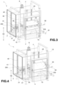
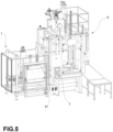
- an unloading apparatus for extracting a piece from a blanking press 9 has been referred to collectively as reference number 1.
- the apparatus 1 comprises:
- the extraction group 2 comprises:
- said collection tray 20 when the extraction group 2 is in the raised position S, said collection tray 20 is operable in translation along a horizontal axis X-X, between an advanced extraction position E for collecting the piece, and a retracted receiving position R.
- the tray 20 has at least one free side 250 which extends in a substantially parallel direction to said horizontal axis X-X.
- said collection tray 20 when the extraction group 2 is in the lowered position A, said collection tray 20 is operable in rotation between a loading configuration C and an unloading configuration SC in which said tray is rotated with respect to the loading configuration, for unloading the piece from the free side 250 of the collection tray 20.
- providing for the piece to be collected from the press at an extraction height H1 and for the same piece to be unloaded at an unloading height H2 that is lower than the extraction height H1 allows the collecting and unloading operations to be separated into two separate moments, simplifying the mechanisms involved in the two operations, and most importantly, allowing the piece to be handled for unloading only when a lower height is reached, which provides greater safety for the operators managing the process.
- the primary frame 10 is substantially box-shaped, with four pillars, one at each corner of the primary frame 10.
- the primary frame 10 is shaped in such a way as to contain the extraction group 2 while simultaneously allowing the translation of the collection tray 20 and the passage of the piece.
- the apparatus 1 comprises:
- the longitudinal sliding members 41 are stably constrained with the secondary frame 200 of the extraction group 2 so that the extraction group 2 is slidable in said longitudinal sliding guides 40.
- the apparatus 1 comprises:
- said transverse sliding members 31 are stably constrained with said collection tray 20, so that the collection tray 20 is slidable in said transverse sliding guides 30.
- the transverse sliding members 31 are engaged with a carriage-carrier cross 300.
- This carriage-carrier cross 300 is engaged with the collection tray 20, so that said carriage-carrier cross 300 is also slidable in the horizontal axis X-X.
- This carriage-carrier cross 300 is suitable for balancing the weight of the collection tray 20 when it is in the extraction position E and houses the piece, so as to avoid sudden movements or breakage of the apparatus 1.
- the apparatus 1 comprises a second pneumatic piston 55 supported by the secondary frame 200 and engaged with the collection tray 20 in an engagement portion 25 of said collection tray 20, so that said collection tray 20 is operable in rotation by the translation of said second pneumatic piston 55.
- the apparatus 1 also comprises a chute element 70 supported by the primary frame 1, and the collection tray 20, when it is in the unloading configuration SC, is aligned with said chute element 70 along said free side 250 to facilitate the unloading of the piece.
- the apparatus 1 comprises:
- the electric motor 6 is of the brushless type.
- the electric motor 6 comprises an inverter.
- the inverter allows the extraction and unloading cycle to be managed precisely and the operating speed to be optimized.
- the transmission members 61 comprise a worm screw element 610 and a nut, or screw nut, 611 engaged with the extraction group 2.
- the electric motor 6 engages and rotatably moves said worm screw element 610, causing the extraction group 2 to be translated along the vertical axis Z-Z.
- the transmission members 61 also comprise a connection joint 620, suitable for connecting the electric motor 6 to the worm screw element 610.
- the transmission members 61 also comprise a support element 630, such as a bearing, suitable for supporting said worm screw element 610 in such a way as to allow it to rotate and simultaneously support part of its weight.
- a support element 630 such as a bearing
- the apparatus 1 comprises a control unit 7, operatively connected with the extraction group 2 and with the electric motor 6, suitable for controlling the activation of the extraction group 2 and of the tray 20.
- the primary frame 10 comprises ground support feet 80, suitable for supporting said apparatus 1 and for counteracting any misalignments and undesired movements due to evacuation operations.
- These support feet 80 comprise adjustment means suitable for enabling a height adjustment of said support feet 80, so that said apparatus 1 may be leveled.
- the apparatus 1 comprises connection elements 81 housed on the primary frame 10, suitable for engaging the apparatus 1 with a blanking press 9.
- the apparatus 1 comprises auxiliary connection arms 82 housed on the primary frame 10, suitable for entering into contact with the blanking press 9 and suitable for counteracting any misalignments and/or undesired movements due to the extraction operations.
- the apparatus 1 further comprises protective panels housed on said primary frame 10, suitable for isolating the apparatus 1 and preventing undesired contact with an operator.
- control unit 7 is suitable for processing a signal coming from the blanking press 9, and is suitable for translating said signal into a maximum stroke Hmax of the extraction group 2 along the vertical axis Z-Z.
- the apparatus 1 comprises movement sensors, e.g., absolute encoders, housed on the primary frame 10 or in the motor 6.
- movement sensors e.g., absolute encoders
- Said movement sensors are suitable for detecting the effective translation height Heff of the extraction group 2.
- the control unit 7 enables the translation of the extraction group 2 in accordance with a detection of the movement sensors of an effective height Heff lower than said maximum stroke Hmax, and the control unit 7 blocks the translation of the extraction group 2 in accordance with a detection of the movement sensors of an effective height Heff equal to said maximum stroke Hmax.
- control unit 7 is suitable for transposing said maximum stroke Hmax into a maximum number of motor revolutions, and suitable for forcing the electric motor 6 to perform said maximum number of engine revolutions, so as to adjust the translation of the extraction group 2 along the vertical axis Z-Z.
- the present invention also relates to a blanking system comprising a blanking press 9 and an apparatus 1 according to the invention, applied to the blanking press.
- the present invention also relates to a method of extracting a piece exiting a blanking press 9, said method comprising the steps of:
- the unloading apparatus for extracting a piece from a blanking press, the blanking system, and the extraction method described above largely fulfill the object of the present invention by overcoming the typical problems of the prior art.
- the unloading apparatus optimizes the processes of extracting and unloading pieces from a blanking press.
- the unloading apparatus operates in total safety for the people using it, such as maintenance workers and/or toolmakers.
- the unloading apparatus operates in total safety for those components that compose it (i.e. worm screw element, tray).
- control unit activates the movements of the unloading apparatus according to what is happening inside the blanking press.
- the unloading apparatus makes it possible to automate the extraction process without directly involving an operator, who is required only to remotely control the process via the control unit.
- the extraction method according to the invention makes it possible to shorten the time required to carry out piece extraction and unloading operations.
Landscapes
- Engineering & Computer Science (AREA)
- Mechanical Engineering (AREA)
- Press Drives And Press Lines (AREA)
- Electrical Discharge Machining, Electrochemical Machining, And Combined Machining (AREA)
- Presses And Accessory Devices Thereof (AREA)
Applications Claiming Priority (1)
| Application Number | Priority Date | Filing Date | Title |
|---|---|---|---|
| IT102021000024950A IT202100024950A1 (it) | 2021-09-29 | 2021-09-29 | Apparato di scarico per una pressa di tranciatura |
Publications (1)
| Publication Number | Publication Date |
|---|---|
| EP4159366A1 true EP4159366A1 (de) | 2023-04-05 |
Family
ID=79019278
Family Applications (1)
| Application Number | Title | Priority Date | Filing Date |
|---|---|---|---|
| EP22198421.4A Pending EP4159366A1 (de) | 2021-09-29 | 2022-09-28 | Entladevorrichtung für eine stanzpresse |
Country Status (2)
| Country | Link |
|---|---|
| EP (1) | EP4159366A1 (de) |
| IT (1) | IT202100024950A1 (de) |
Citations (6)
| Publication number | Priority date | Publication date | Assignee | Title |
|---|---|---|---|---|
| JPS62248523A (ja) * | 1986-04-18 | 1987-10-29 | Aida Eng Ltd | プレス機械の製品取出装置 |
| CN109277867A (zh) * | 2018-08-01 | 2019-01-29 | 无锡庆源激光科技有限公司 | 一种切管机零尾料自动下料装置 |
| CN109433934A (zh) * | 2018-12-20 | 2019-03-08 | 江苏泽恩汽机车部品制造有限公司 | 一种带自动卸废料装置的冲压模具 |
| CN111204076A (zh) * | 2019-12-31 | 2020-05-29 | 太田机械江苏有限公司 | 一种液压机用快速上料机 |
| CN210967189U (zh) * | 2019-08-26 | 2020-07-10 | 惠州市泰铭五金有限公司 | 一种新型智能数控液压剪板机 |
| CN112477254A (zh) * | 2020-10-28 | 2021-03-12 | 苏州华怡炉料再生有限公司 | 一种可自动出料的废旧金属回收用压块装置 |
-
2021
- 2021-09-29 IT IT102021000024950A patent/IT202100024950A1/it unknown
-
2022
- 2022-09-28 EP EP22198421.4A patent/EP4159366A1/de active Pending
Patent Citations (6)
| Publication number | Priority date | Publication date | Assignee | Title |
|---|---|---|---|---|
| JPS62248523A (ja) * | 1986-04-18 | 1987-10-29 | Aida Eng Ltd | プレス機械の製品取出装置 |
| CN109277867A (zh) * | 2018-08-01 | 2019-01-29 | 无锡庆源激光科技有限公司 | 一种切管机零尾料自动下料装置 |
| CN109433934A (zh) * | 2018-12-20 | 2019-03-08 | 江苏泽恩汽机车部品制造有限公司 | 一种带自动卸废料装置的冲压模具 |
| CN210967189U (zh) * | 2019-08-26 | 2020-07-10 | 惠州市泰铭五金有限公司 | 一种新型智能数控液压剪板机 |
| CN111204076A (zh) * | 2019-12-31 | 2020-05-29 | 太田机械江苏有限公司 | 一种液压机用快速上料机 |
| CN112477254A (zh) * | 2020-10-28 | 2021-03-12 | 苏州华怡炉料再生有限公司 | 一种可自动出料的废旧金属回收用压块装置 |
Also Published As
| Publication number | Publication date |
|---|---|
| IT202100024950A1 (it) | 2023-03-29 |
Similar Documents
| Publication | Publication Date | Title |
|---|---|---|
| US9555511B2 (en) | Apparatus for the assembly and disassembly of hydraulic cylinders | |
| EP3450704B1 (de) | Turbinenlagerwartungsvorrichtung und -verfahren | |
| CN108501139B (zh) | 多位置打钉设备 | |
| CN106736487B (zh) | 一种全自动拆螺丝的设备 | |
| US20020170333A1 (en) | Hemming machine with movable die cartridges | |
| EP4159366A1 (de) | Entladevorrichtung für eine stanzpresse | |
| US5301867A (en) | Machine for breaking glass plate | |
| IT201800009564A1 (it) | Sistema compatto e preassemblato di lavorazione automatico | |
| GB1308563A (en) | Machine tool with rotary work-table | |
| US6796158B2 (en) | Adjustable knockout assembly for a press system | |
| US3217526A (en) | Rolling mills roll change | |
| CN111251076B (zh) | 用于铝压铸产品生产与加工的智能自动化产线及其操作方法 | |
| KR101158355B1 (ko) | 빌렛 및 튜브용 압출 프레스 | |
| EP2397294A2 (de) | Seitenwandeinheit für Gussform und Beseitigungseinheit für Seitenwandeinheit | |
| EP3437752B1 (de) | Mehrstufiges karussell zum wechseln von werkzeug und matrize einer presse | |
| CN112171816B (zh) | 一种用于胶合板热压的加工设备 | |
| KR101734359B1 (ko) | 오일미스트 포집을 위한 단조 라인의 흄 후드 장치 | |
| EP4194122A1 (de) | Schneidpresse und verfahren zur reinigung einer halbform | |
| CN116833357B (zh) | 一种锻件加工用取件装置及其使用方法 | |
| EP3829842B1 (de) | System und verfahren zum bewegen eines blocks aus steinmaterial | |
| CN118512812A (zh) | 一种压滤机自动清理方法 | |
| CN216298079U (zh) | 一种产品表面铣削装置 | |
| US2878559A (en) | Mounting and demounting press | |
| CN111992980B (zh) | 一种挺柱表面精加工处理设备 | |
| SU725901A1 (ru) | Устройство дл установки и сн ти прессформ со стола пресса |
Legal Events
| Date | Code | Title | Description |
|---|---|---|---|
| PUAI | Public reference made under article 153(3) epc to a published international application that has entered the european phase |
Free format text: ORIGINAL CODE: 0009012 |
|
| STAA | Information on the status of an ep patent application or granted ep patent |
Free format text: STATUS: THE APPLICATION HAS BEEN PUBLISHED |
|
| AK | Designated contracting states |
Kind code of ref document: A1 Designated state(s): AL AT BE BG CH CY CZ DE DK EE ES FI FR GB GR HR HU IE IS IT LI LT LU LV MC MK MT NL NO PL PT RO RS SE SI SK SM TR |
|
| STAA | Information on the status of an ep patent application or granted ep patent |
Free format text: STATUS: REQUEST FOR EXAMINATION WAS MADE |
|
| 17P | Request for examination filed |
Effective date: 20231005 |
|
| RBV | Designated contracting states (corrected) |
Designated state(s): AL AT BE BG CH CY CZ DE DK EE ES FI FR GB GR HR HU IE IS IT LI LT LU LV MC MK MT NL NO PL PT RO RS SE SI SK SM TR |
|
| STAA | Information on the status of an ep patent application or granted ep patent |
Free format text: STATUS: EXAMINATION IS IN PROGRESS |
|
| 17Q | First examination report despatched |
Effective date: 20240502 |