EP4159099A2 - Bodengestützter roboter - Google Patents
Bodengestützter roboter Download PDFInfo
- Publication number
- EP4159099A2 EP4159099A2 EP22193196.7A EP22193196A EP4159099A2 EP 4159099 A2 EP4159099 A2 EP 4159099A2 EP 22193196 A EP22193196 A EP 22193196A EP 4159099 A2 EP4159099 A2 EP 4159099A2
- Authority
- EP
- European Patent Office
- Prior art keywords
- robot
- drive
- rocker
- obstacle
- chassis
- Prior art date
- Legal status (The legal status is an assumption and is not a legal conclusion. Google has not performed a legal analysis and makes no representation as to the accuracy of the status listed.)
- Granted
Links
Images


Classifications
-
- A—HUMAN NECESSITIES
- A47—FURNITURE; DOMESTIC ARTICLES OR APPLIANCES; COFFEE MILLS; SPICE MILLS; SUCTION CLEANERS IN GENERAL
- A47L—DOMESTIC WASHING OR CLEANING; SUCTION CLEANERS IN GENERAL
- A47L11/00—Machines for cleaning floors, carpets, furniture, walls, or wall coverings
- A47L11/40—Parts or details of machines not provided for in groups A47L11/02 - A47L11/38, or not restricted to one of these groups, e.g. handles, arrangements of switches, skirts, buffers, levers
- A47L11/4072—Arrangement of castors or wheels
-
- A—HUMAN NECESSITIES
- A47—FURNITURE; DOMESTIC ARTICLES OR APPLIANCES; COFFEE MILLS; SPICE MILLS; SUCTION CLEANERS IN GENERAL
- A47L—DOMESTIC WASHING OR CLEANING; SUCTION CLEANERS IN GENERAL
- A47L11/00—Machines for cleaning floors, carpets, furniture, walls, or wall coverings
- A47L11/40—Parts or details of machines not provided for in groups A47L11/02 - A47L11/38, or not restricted to one of these groups, e.g. handles, arrangements of switches, skirts, buffers, levers
- A47L11/4063—Driving means; Transmission means therefor
-
- A—HUMAN NECESSITIES
- A47—FURNITURE; DOMESTIC ARTICLES OR APPLIANCES; COFFEE MILLS; SPICE MILLS; SUCTION CLEANERS IN GENERAL
- A47L—DOMESTIC WASHING OR CLEANING; SUCTION CLEANERS IN GENERAL
- A47L9/00—Details or accessories of suction cleaners, e.g. mechanical means for controlling the suction or for effecting pulsating action; Storing devices specially adapted to suction cleaners or parts thereof; Carrying-vehicles specially adapted for suction cleaners
- A47L9/009—Carrying-vehicles; Arrangements of trollies or wheels; Means for avoiding mechanical obstacles
-
- A—HUMAN NECESSITIES
- A47—FURNITURE; DOMESTIC ARTICLES OR APPLIANCES; COFFEE MILLS; SPICE MILLS; SUCTION CLEANERS IN GENERAL
- A47L—DOMESTIC WASHING OR CLEANING; SUCTION CLEANERS IN GENERAL
- A47L9/00—Details or accessories of suction cleaners, e.g. mechanical means for controlling the suction or for effecting pulsating action; Storing devices specially adapted to suction cleaners or parts thereof; Carrying-vehicles specially adapted for suction cleaners
- A47L9/28—Installation of the electric equipment, e.g. adaptation or attachment to the suction cleaner; Controlling suction cleaners by electric means
- A47L9/2836—Installation of the electric equipment, e.g. adaptation or attachment to the suction cleaner; Controlling suction cleaners by electric means characterised by the parts which are controlled
- A47L9/2852—Elements for displacement of the vacuum cleaner or the accessories therefor, e.g. wheels, casters or nozzles
-
- A—HUMAN NECESSITIES
- A47—FURNITURE; DOMESTIC ARTICLES OR APPLIANCES; COFFEE MILLS; SPICE MILLS; SUCTION CLEANERS IN GENERAL
- A47L—DOMESTIC WASHING OR CLEANING; SUCTION CLEANERS IN GENERAL
- A47L2201/00—Robotic cleaning machines, i.e. with automatic control of the travelling movement or the cleaning operation
Definitions
- the invention relates to a ground-based robot.
- the invention relates to a drive system of a floor-based robot.
- a floor-based robot is set up to travel over a floor area automatically or autonomously.
- the robot can be designed in particular as a floor cleaning robot, for example for use in a household.
- a treatment device for cleaning the floor area traveled over is often provided, for example in the form of a suction, sweeping or wiping device.
- the robot includes a left and a right drive device, which can be controlled evenly to enable straight travel or unevenly to realize cornering.
- a drive device usually includes a drive wheel mounted on a swing arm in order to transmit a traction force to the ground.
- the swingarm is resiliently mounted relative to a chassis.
- a trailed swingarm in which an axis of rotation between the swingarm and the chassis lies in front of an axis of rotation of the drive wheel with respect to a direction of travel, can ensure good power transmission.
- the drive device takes up a large installation space in front of the drive device in the direction of travel, which space is then not available for the processing device.
- An object on which the present invention is based is to specify an improved drive concept for a floor-supported robot.
- the invention solves this problem by means of the subject matter of the independent claims. Subclaims reflect preferred embodiments.
- a floor-based robot includes a chassis; a first drive mechanism attached to the chassis by a first link; and a second drive mechanism attached to the chassis by a second link.
- the drive devices are attached on different sides with respect to a direction of movement and the first rocker is designed as a pushed rocker and the second rocker as a pulled rocker.
- a maximum traction force that can be transmitted by means of a drive device mounted on a rocker is dependent on an orientation of the rocker.
- the pulled swing arm can transmit significantly more traction when overcoming obstacles than the pushed swing arm. In practical tests for overcoming obstacles, almost twice as much traction force could be achieved with a pulled rocker as with a pushed rocker. With a uniform, straight-line movement, there are no differences between the pulled and the pushed swing arm.
- the mutually oriented rocker arms rotated by 180° can transmit comparably large traction forces to a substrate. If the robot encounters an obstacle, such as a vertical step or threshold, the forces acting on the left and right of the chassis can differ, so that the robot can automatically drive over the obstacle at an angle.
- the drive device with the pulled rocker can drive over the obstacle first, and the drive device with the pushed rocker can follow. Due to the anti-parallel oriented wings, an asymmetrically acting propulsion force can be automatically generated to overcome an obstacle. It is not necessary to recognize the obstacle before driving over it.
- the robot can further include a processing device for a traveled floor surface.
- the robot can be set up as a household appliance.
- the processing device is preferably set up for cleaning and/or maintaining the floor surface and can process the floor surface dry or using a liquid.
- the processing device comprises a suction device, a sweeping device or a wiping device.
- the processing device extends into an area in front of the first rocker.
- the installation space on the chassis made available by the pushed rocker compared to the pulled rocker can be better used to accommodate the machining device.
- the processing device can be located in front of the drive device in the direction of travel, so that a floor area can be processed first and only then can it be driven on.
- the processing device can also be designed or attached asymmetrically with respect to a longitudinal axis of the robot.
- the machining device and the first drive device can essentially extend as far as a lateral boundary of the chassis. If the pushed rocker is attached to the chassis on the right, for example in the direction of travel, a right-hand boundary of the processing device and the drive device can be similarly far away from a longitudinal axis of the robot and preferably essentially coincide with a right-hand boundary of the chassis. In this direction, the chassis can still have a certain amount of additional installation space for accommodating a housing or a side wall. On the right side, the robot can guide the processing device closer to a wall or other boundary across the floor surface.
- the processing device can include a suction mouth.
- the suction mouth can form a near-ground end of a suction channel that leads to a fan.
- the suction mouth can be guided over the floor surface at a predetermined distance when the robot is driving. So the floor surface can be cleaned by vacuuming.
- the processing device can also include a powered brush.
- the brush can be designed, for example, as a brush roller that can be rotated about a horizontal axis of rotation, or as a brush wheel that can be rotated about a vertical axis of rotation. Bristles or bristles of the brush may extend beyond an outline of the chassis robot.
- a drive device has a drive motor attached to the associated rocker.
- a torque provided by the drive motor for traction can be supported relative to the rocker, so that a vertically acting force can result, which pivots the rocker in or out.
- the rocker is more preferably supported with respect to the chassis by means of an elastic element, which can support a raising or lowering of the chassis with respect to the floor surface in the event of variations in the vertically acting force.
- a drive device has a drive wheel that is set up to transmit a traction force to a ground.
- the drive device can be easy to implement and resistant to dirt.
- the ground may include an obstacle lying on the floor surface or incorporated into the floor surface. The obstacle can extend in the vertical direction and preferably affects both drive devices.
- a drive device in another embodiment, includes a traction drive that is set up to transmit a traction force to a ground.
- the traction mechanism can in particular include a belt drive, a toothed belt drive or a chain drive. Wheels or pinions of the traction drive can be the same size or different sizes.
- a lower strand of the traction device can rest on the ground during normal operation or in a predetermined driving operation.
- a traction force that can be transmitted to the ground can be increased by means of the traction drive.
- the drive devices are constructed in the same way. In this way, identical parts can be used on the robot in an improved manner, which can help to reduce development and production costs. Storage of spare parts can be simplified.
- a method for controlling a robot described herein comprises steps of detecting that the first driving device and the second driving device are exposed to an obstacle on the floor surface; driving the second drive means to overcome the obstacle; and driving the first drive device to overcome the obstacle.
- the method can be carried out by means of a control device, which can be comprised by a robot described herein.
- the control device can comprise a programmable microcomputer or microcontroller and the method can be in the form of a computer program product with program code means.
- the computer program product can also be stored on a computer-readable data carrier. Additional features or advantages of the method can be transferred to the corresponding device or vice versa.
- Figures 1 and 2 each show a schematic representation of a robot 100, which is preferably constructed as a household appliance and set up to be used in a household. More preferably, the robot 100 is used within one or more connected closed rooms.
- the robot 100 can be set up to drive autonomously on a floor surface 105 . In doing so, he can process and in particular clean the floor surface 105 .
- the robot 100 can be constructed as a cleaning robot, for example as a sweeping, wiping or vacuum cleaning robot.
- the robot 100 includes in the Figures 1 and 2 one drive device 110 each, which is attached here by way of example to a right-hand side of the robot 100 .
- the drive device 110 can also be provided on a left-hand side of the robot 100 .
- the robot 100 also includes a chassis 115, which can be constructed, for example, as a floor pan, floor panel or floor assembly. The purpose of the chassis 115 is to accommodate the drive devices 110 and preferably other components of the robot 100, to attach them to one another or to support them against one another.
- the drive device 110 comprises a drive wheel 120 which is mounted on a rocker 130 so as to be rotatable about a first axis of rotation 125 .
- the drive wheel 120 can be rotated about the first axis of rotation 125 with respect to the rocker 130 by means of a drive motor 135 .
- An end of the rocker arm 130 remote from the drive wheel 120 is rotatably mounted relative to the chassis 115 about a second axis of rotation 140 .
- An elastic element 145 can be provided in order to press the rocker 130 against the weight of the chassis 115 against the floor surface 105 .
- FIGs 1 and 2 differ in the orientation of the rocker 130 with respect to an intended or usual direction of travel 150 of the robot 100, which is shown symbolically as a block arrow.
- a pushed rocker 130 is shown, in which the first axis of rotation 125 lies in front of the second axis of rotation 140 with respect to the direction of travel 150 .
- a trailed rocker arm 130 is shown, in which the first axis of rotation 125 lies behind the second axis of rotation 140 with respect to the direction of travel 150 .
- the robot 100 encounters a vertical obstacle 155, for example a step or a doorstep, when driving in the direction of travel 150, an increased torque is applied the drive wheels 120 needed to lift the robot 100 and overcome the obstacle 155.
- a vertical obstacle 155 for example a step or a doorstep
- the torque provided by the drive motor 135 also promotes a rebound of the rocker 130.
- the obstacle 155 makes an effective lever between the second axis of rotation 140 and a contact point of the drive wheel 120 on the floor surface 105 longer, so that the vertical Direction acting force is reduced.
- the drive wheel 120 tends to slide down the obstacle 155 .
- a traction force that can be transmitted to the floor surface 105 can be reduced overall.
- the torque favors a deflection of the rocker 130.
- the effective lever between the second axis of rotation 140 and the contact point of the drive wheel 120 on the ground surface is shortened by the obstacle 155.
- the lever 135 presses the drive wheel 120 improved to the edge of the obstacle 155 so that it climbs the obstacle 155 improved.
- a traction force that can be transmitted to the floor surface 105 can be increased overall.
- a robot with a drive device 110 on a pushed rocker 130 of the type figure 1 and a drive device 110 on a towed swingarm 130 of the type figure 2 equip.
- the drive devices 110 should lie on different sides of a longitudinal axis of the robot 100 .
- the robot 100 may be supported against the floor surface 105 by means of a wheel or a slide surface.
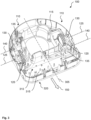
- figure 3 12 shows a low-level assembly of a robot 100 in an exemplary embodiment.
- the sides of the robot 100 are labeled with respect to a preferred direction of travel 150 .
- the axes of rotation 125 of the drive wheels 120 are essentially at the same height in relation to a longitudinal direction of the robot 100.
- the swing arm 130 extends forward in the left drive assembly 110 and rearward in the right drive assembly 110 .
- the drive motor 135 is located on the left drive assembly 110 in front of the drive wheel 120 and on the right Drive device 110 behind. Accordingly, there is more free space in front of the right-hand drive device 110 than in front of the left-hand drive device 110 .
- a fan connected to the suction duct 315 or a dirt separator are not in figure 3 shown.
- the processing device 310 is located asymmetrically on the robot 100 in the transverse direction in the free installation space and can in particular be placed off-center to such an extent that an inaccessible section of the floor surface 105 when the robot 100 drives along a wall on its right-hand side is minimized.
- figure 4 shows a robot in different phases when overcoming an obstacle 155 in a plan view.
- the phases can also be viewed as steps of a method 400 .
- the robot 100 and the obstacle 155 are shown schematically.
- both drive wheels 120 have moved up to the obstacle 155. Should the robot 100 approach the obstacle 155 at an angle, the drive wheel 120 which reaches the obstacle 155 first can be braked until the other drive wheel 120 has reached the obstacle 155 . It can then be detected that the obstacle 155 acts on both drive devices 110 .
- a second phase 410 the drive device 110 with the pulled rocker 130, which is attached here on the right side of the robot 100, exerts a greater traction force on the floor surface 105 than the drive device 110 with the pushed rocker 130, which is present on the left Side of the robot 100 is attached.
- the right drive wheel 120 climbs up and over the obstacle 155 while the left drive wheel 120 still lags behind.
- the robot 100 is no longer perpendicular to the obstacle 155, but encloses an acute angle with it, which is preferably between approximately 45° and approximately 90°. To control the angle, the left drive assembly 110 can be decelerated or stopped.
- a profile of the drive wheel 120 can engage in the obstacle 155 in a form-fitting or improved non-positive manner.
- the left drive wheel 120 follows the right drive wheel 120 by climbing up the obstacle 155 and overcoming it.
- the right one can do this Drive device 110 are braked or stopped. Subsequently, the robot 100 can continue its activity beyond the obstacle 155 .
Landscapes
- Engineering & Computer Science (AREA)
- Mechanical Engineering (AREA)
- Manipulator (AREA)
- Electric Suction Cleaners (AREA)
Abstract
Description
- Die Erfindung betrifft einen bodengestützten Roboter. Insbesondere betrifft die Erfindung ein Antriebssystem eines bodengestützten Roboters.
- Ein bodengestützter Roboter ist dazu eingerichtet, eine Bodenfläche automatisch oder autonom zu befahren. Der Roboter kann insbesondere als Bodenreinigungsroboter ausgeführt sein, beispielsweise zum Einsatz in einem Haushalt. Dabei ist häufig eine Bearbeitungseinrichtung zur Reinigung der befahrenen Bodenfläche vorgesehen, beispielsweise in Form einer Saug-, Kehr- oder Wischeinrichtung.
- Der Roboter umfasst eine linke und eine rechte Antriebseinrichtung, die gleichmäßig angesteuert werden können, um eine Geradeausfahrt zu ermöglichen, oder ungleichmäßig, um eine Kurvenfahrt zu realisieren. Üblicherweise umfasst eine Antriebseinrichtung ein an einer Schwinge gelagertes Antriebsrad, um eine Traktionskraft an den Untergrund zu übertragen. Die Schwinge ist federnd gegenüber einem Chassis gelagert. Insbesondere eine gezogene Schwinge, bei der eine Drehachse zwischen der Schwinge und dem Chassis bezüglich einer Fahrtrichtung vor einer Drehachse des Antriebsrads liegt, kann eine gute Kraftübertragung sicherstellen. Allerdings wird dabei durch die Antriebseinrichtung ein großer in Fahrtrichtung vor der Antriebseinrichtung liegender Bauraum eingenommen, der dann für die Bearbeitungseinrichtung nicht zur Verfügung steht.
- Eine der vorliegenden Erfindung zu Grunde liegende Aufgabe besteht in der Angabe eines verbesserten Antriebskonzepts für einen bodengestützten Roboter. Die Erfindung löst diese Aufgabe mittels der Gegenstände der unabhängigen Ansprüche. Unteransprüche geben bevorzugte Ausführungsformen wieder.
- Nach einem Aspekt der vorliegenden Erfindung umfasst ein bodengestützter Roboter ein Chassis; eine erste Antriebseinrichtung, die mittels einer ersten Schwinge am Chassis angebracht ist; und eine zweite Antriebseinrichtung, die mittels einer zweiten Schwinge am Chassis angebracht ist. Dabei sind die Antriebseinrichtungen auf unterschiedlichen Seiten bezüglich einer Bewegungsrichtung angebracht und die erste Schwinge ist als geschobene Schwinge und die zweite Schwinge als gezogene Schwinge ausgeführt. Erfindungsgemäß wurde erkannt, dass eine maximal mittels einer an einer Schwinge gelagerten Antriebseinrichtung übertragbare Traktionskraft von einer Orientierung der Schwinge abhängig ist. Die gezogene Schwinge kann deutlich mehr Traktionskräfte beim Überwinden von Hindernissen übermitteln als die geschobene Schwinge. In praktischen Versuchen zur Hindernisüberwindung konnte mittels einer gezogenen Schwinge annähernd doppelt so viel Traktionskraft wie mittels einer geschobenen Schwinge bewirkt werden. Bei einer gleichförmigen, geradlinigen Bewegung gib es keine Unterschiede zwischen der gezogenen und der geschobenen Schwinge.
- In einem üblichen Betrieb des Roboters, wenn kein Hindernis zu überwinden ist, können die gegeneinander um 180° verdreht orientierten Schwingen vergleichbar große Traktionskräfte auf einen Untergrund übertragen. Gerät der Roboter an ein Hindernis, beispielsweise eine vertikale Stufe oder Schwelle, so können die links und rechts auf das Chassis wirkenden Kräfte voneinander abweichen, sodass der Roboter das Hindernis automatisch schräg überfahren kann. Die Antriebseinrichtung mit der gezogenen Schwinge kann das Hindernis zuerst überfahren, und die Antriebseinrichtung mit der geschobenen Schwinge kann nachfolgen. Durch die antiparallel orientierten Schwingen kann automatisch eine asymmetrisch wirkende Vortriebskraft zur Überwindung eines Hindernisses bewirkt werden. Eine Erkennung des Hindernisses vor dem Überfahren ist dazu nicht erforderlich.
- Der Roboter kann ferner eine Bearbeitungsvorrichtung für eine befahrene Bodenfläche umfassen. Der Roboter kann insbesondere als Haushaltsgerät eingerichtet sein. Die Bearbeitungsvorrichtung ist bevorzugt zur Reinigung und/oder Pflege der Bodenfläche eingerichtet und kann die Bodenfläche trocken oder unter Einsatz einer Flüssigkeit bearbeiten. In einer Ausführungsform umfasst die Bearbeitungsvorrichtung eine Saugeinrichtung, eine Kehreinrichtung oder eine Wischeinrichtung.
- Es ist bevorzugt, dass sich die Bearbeitungsvorrichtung in einen Bereich vor der ersten Schwinge erstreckt. Der durch die geschobene Schwinge gegenüber der gezogenen Schwinge freigewordene Bauraum am Chassis kann besser dazu verwendet werden, die Bearbeitungsvorrichtung aufzunehmen. Dadurch kann die Bearbeitungsvorrichtung in Fahrtrichtung vor der Antriebseinrichtung liegen, sodass eine Bodenfläche zuerst bearbeitet und erst danach befahren werden kann. Optional kann die Bearbeitungsvorrichtung auch asymmetrisch bezüglich einer Längsachse des Roboters ausgebildet oder angebracht sein.
- Die Bearbeitungsvorrichtung und die erste Antriebseinrichtung können sich im Wesentlichen bis zu einer seitlichen Begrenzung des Chassis erstrecken. Ist die geschobene Schwinge beispielsweise in Fahrtrichtung rechts am Chassis angebracht, so können eine rechte Begrenzung der Bearbeitungsvorrichtung und der Antriebseinrichtung ähnlich weit von einer Längsachse des Roboters entfernt sein und fallen bevorzugt im Wesentlichen mit einer rechten Begrenzung des Chassis zusammen. Das Chassis kann in dieser Richtung noch einen gewissen zusätzlichen Bauraum zur Aufnahme eines Gehäuses oder einer Seitenwand aufweisen. An der rechten Seite kann der Roboter die Bearbeitungsvorrichtung näher bis an eine Wand oder eine andere Begrenzung hin über die Bodenfläche führen.
- Die Bearbeitungsvorrichtung kann einen Saugmund umfassen. Der Saugmund kann ein bodennahes Ende eines Saugkanals bilden, der zu einem Gebläse führt. Der Saugmund kann in einem vorbestimmten Abstand über die Bodenfläche geführt werden, wenn der Roboter fährt. So kann die Bodenfläche mittels Saugens gereinigt werden.
- Die Bearbeitungsvorrichtung kann auch eine angetriebene Bürste umfassen. Die Bürste kann beispielsweise als Bürstenwalze ausgeführt sein, die um eine horizontale Drehachse gedreht werden kann, oder als Bürstenrad, das um eine vertikale Drehachse gedreht werden kann. Borsten oder Pinsel der Bürste können sich bis über einen Umriss des Chassis Roboters erstrecken.
- In einer Ausführungsform weist eine Antriebseinrichtung einen an der zugeordneten Schwinge angebrachten Antriebsmotor auf. Dadurch kann ein durch den Antriebsmotor zur Traktion bereitgestelltes Drehmoment gegenüber der Schwinge abgestützt sein, sodass sich eine vertikal wirkende Kraft ergeben kann, welche die Schwinge ein- oder ausschwenkt. Die Schwinge ist weiter bevorzugt mittels eines elastischen Elements gegenüber dem Chassis abgestützt, das bei Variationen der vertikal wirkenden Kraft ein Anheben oder Absenken des Chassis gegenüber der Bodenfläche unterstützen kann.
- In einer Ausführungsform weist eine Antriebseinrichtung ein Antriebsrad auf, das dazu eingerichtet ist, eine Traktionskraft an einen Untergrund zu übermitteln. So kann die Antriebseinrichtung einfach zu realisieren und resistent gegen Schmutz sein. Der Untergrund kann ein auf der Bodenfläche liegendes oder in die Bodenfläche eingearbeitetes Hindernis umfassen. Das Hindernis kann sich in vertikaler Richtung erstrecken und betrifft bevorzugt beide Antriebseinrichtungen.
- In einer anderen Ausführungsform umfasst eine Antriebseinrichtung einen Zugmitteltrieb, der dazu eingerichtet ist, eine Traktionskraft an einen Untergrund zu übermitteln. Der Zugmitteltrieb kann insbesondere einen Riementrieb, einen Zahnriementrieb oder einen Kettentrieb umfassen. Räder oder Ritzel des Zugmitteltriebs können gleich oder unterschiedlich groß sein. Ein unteres Trum des Zugmittels kann im Normalbetrieb oder in einem vorbestimmten Fahrbetrieb auf dem Untergrund aufliegen. Mittels des Zugmitteltriebs kann eine auf den Untergrund übertragbare Traktionskraft vergrößert sein.
- Es ist besonders bevorzugt, dass die Antriebseinrichtungen baugleich ausgeführt sind. So können verbessert Gleichteile am Roboter eingesetzt werden, was Entwicklungs- und Produktionskosten verringern helfen kann. Eine Lagerhaltung für Ersatzteile kann vereinfacht sein.
- Nach einem weiteren Aspekt der vorliegenden Erfindung umfasst ein Verfahren zum Steuern eines hierin beschriebenen Roboters Schritte des Erfassens, dass die erste Antriebseinrichtung und die zweite Antriebseinrichtung einem Hindernis auf der Bodenfläche ausgesetzt sind; des Ansteuerns der zweiten Antriebseinrichtung, um das Hindernis zu überwinden; und des Ansteuerns der ersten Antriebseinrichtung, um das Hindernis zu überwinden.
- Das Verfahren kann mittels einer Steuervorrichtung durchgeführt sein, die von einem hierin beschriebenen Roboter umfasst sein kann. Die Steuervorrichtung kann einen programmierbaren Mikrocomputer oder Mikrocontroller umfassen und das Verfahren kann in Form eines Computerprogrammprodukts mit Programmcodemitteln vorliegen. Das Computerprogrammprodukt kann auch auf einem computerlesbaren Datenträger abgespeichert sein. Merkmale oder Vorteile des Verfahrens können auf die korrespondierende Vorrichtung übertragen werden oder umgekehrt.
- Die Erfindung wird nun unter Bezug auf die beiliegenden Figuren genauer beschrieben, in denen:
- Figur 1
- eine geschobene Schwinge an einem Roboter;
- Figur 2
- eine gezogene Schwinge an einem Roboter;
- Figur 3
- eine bodennahe Baugruppe eines Roboters; und
- Figur 4
- einen Roboter in verschiedenen Phasen bei der Überwindung eines Hindernisses
-
Figuren 1 und 2 zeigen jeweils eine schematische Darstellung eines Roboters 100, der bevorzugt als Haushaltsgerät aufgebaut und dazu eingerichtet ist, in einem Haushalt eingesetzt zu werden. Weiter bevorzugt wird der Roboter 100 innerhalb eines oder mehrerer zusammenhängender geschlossener Räume eingesetzt. Der Roboter 100 kann dazu eingerichtet sein, autonom auf einer Bodenfläche 105 zu fahren. Dabei kann er die Bodenfläche 105 bearbeiten und insbesondere reinigen. Dazu kann der Roboter 100 als Reinigungsroboter, etwa als Kehr-, Wisch- oder Staubsaugroboter aufgebaut sein. - Der Roboter 100 umfasst in den
Figuren 1 und 2 jeweils eine Antriebseinrichtung 110, die hier beispielhaft an einer rechten Seite des Roboters 100 angebracht ist. In entsprechender Weise kann die Antriebseinrichtung 110 auch an einer linken Seite des Roboters 100 vorgesehen sein. Weiter umfasst der Roboter 100 ein Chassis 115, das beispielsweise als Bodenwanne, Bodenblech oder Bodenbaugruppe aufgebaut sein kann. Das Chassis 115 hat die Aufgabe, die Antriebseinrichtungen 110 und bevorzugt noch weitere Komponenten des Roboters 100 aufzunehmen, aneinander zu befestigen oder gegeneinander zu lagern. - Die Antriebseinrichtung 110 umfasst vorliegend ein Antriebsrad 120, das um eine erste Drehachse 125 an einer Schwinge 130 drehbar gelagert ist. Mittels eines Antriebsmotors 135 kann das Antriebsrad 120 bezüglich der Schwinge 130 um die erste Drehachse 125 gedreht werden. Ein vom Antriebsrad 120 entferntes Ende der Schwinge 130 ist um eine zweite Drehachse 140 drehbar gegenüber dem Chassis 115 gelagert. Ein elastisches Element 145 kann vorgesehen sein, um die Schwinge 130 entgegen einer Gewichtskraft des Chassis 115 gegen die Bodenfläche 105 zu drücken.
- Die
Figuren 1 und 2 unterscheiden sich in der Orientierung der Schwinge 130 bezüglich einer beabsichtigten oder üblichen Fahrtrichtung 150 des Roboters 100, die symbolisch als Blockpfeil eingezeichnet ist. InFigur 1 ist eine geschobene Schwinge 130 dargestellt, bei der die erste Drehachse 125 bezüglich der Fahrtrichtung 150 vor der zweiten Drehachse 140 liegt. InFigur 2 ist eine gezogene Schwinge 130 dargestellt, bei der die erste Drehachse 125 bezüglich der Fahrtrichtung 150 hinter der zweiten Drehachse 140 liegt. - Gerät der Roboter 100 beim Fahren in Fahrtrichtung 150 an ein vertikales Hindernis 155, beispielsweise eine Stufe oder eine Türschwelle, so wird ein erhöhtes Drehmoment an den Antriebsrädern 120 benötigt, um den Roboter 100 anzuheben und das Hindernis 155 zu überwinden.
- In der Variante von
Figur 1 mit der geschobenen Schwinge 130 begünstigt das durch den Antriebsmotor 135 bereitgestellte Drehmoment gleichzeitig ein Ausfedern der Schwinge 130. Allerdings wird durch das Hindernis 155 ein wirksamer Hebel zwischen der zweiten Drehachse 140 und einem Kontaktpunkt des Antriebsrads 120 an der Bodenfläche 105 länger, sodass die in vertikaler Richtung wirkende Kraft verringert ist. Außerdem tendiert das Antriebsrad 120 dazu, am Hindernis 155 nach unten abzurutschen. Eine auf die Bodenfläche 105 übertragbare Traktionskraft kann insgesamt verringert sein. - In der Variante von
Figur 2 mit der gezogenen Schwinge 130 begünstigt das Drehmoment hingegen ein Einfedern der Schwinge 130. Der wirksame Hebel zwischen der zweiten Drehachse 140 und dem Kontaktpunkt des Antriebsrads 120 an der Bodenfläche wird durch das Hindernis 155 verkürzt. Der Hebel 135 presst das Antriebsrad 120 verbessert an die Kante des Hindernisses 155, sodass es verbessert am Hindernis 155 nach oben klettert. Eine auf die Bodenfläche 105 übertragbare Traktionskraft kann insgesamt erhöht sein. - Es wird vorgeschlagen, einen Roboter mit einer Antriebseinrichtung 110 an einer geschobenen Schwinge 130 der Art von
Figur 1 und einer Antriebseinrichtung 110 an einer gezogenen Schwinge 130 der Art vonFigur 2 auszustatten. Die Antriebseinrichtungen 110 sollen dabei auf unterschiedlichen Seiten einer Längsachse des Roboters 100 liegen. Zusätzlich kann der Roboter 100 mittels eines Rads oder einer Rutschfläche gegenüber der Bodenfläche 105 abgestützt sein. -
Figur 3 zeigt eine bodennahe Baugruppe eines Roboters 100 in einer beispielhaften Ausführungsform. Auf unterschiedlichen Seiten bezüglich einer Längsachse 305 sind eine linke Antriebseinrichtung 110 mit geschobener Schwinge 130 nachFigur 1 und eine rechte Antriebseinrichtung 110 mit gezogener Schwinge 130 nachFigur 2 am Chassis 115 angebracht. Die Seiten des Roboters 100 sind bezüglich einer bevorzugten Fahrtrichtung 150 bezeichnet. Die Drehachsen 125 der Antriebsräder 120 liegen im Wesentlichen auf einer Höhe bezüglich einer Längsrichtung des Roboters 100. - Die Schwinge 130 erstreckt sich in der linken Antriebseinrichtung 110 nach vorn und in der rechten Antriebseinrichtung 110 nach hinten. Der Antriebsmotor 135 befindet sich an der linken Antriebseinrichtung 110 vor dem Antriebsrad 120 und an der rechten Antriebseinrichtung 110 dahinter. Dementsprechend besteht vor der rechten Antriebseinrichtung 110 ein größerer freier Bauraum als vor der linken Antriebseinrichtung 110. Dieser Bauraum kann durch eine Bearbeitungsvorrichtung 310 genutzt werden, die vorliegend einen Saugkanal 315 mit einem Saugmund 320 umfasst. Ein mit dem Saugkanal 315 verbundenes Gebläse oder ein Schmutzabscheider sind nicht in
Figur 3 gezeigt. Die Bearbeitungsvorrichtung 310 liegt im freien Bauraum in Querrichtung asymmetrisch am Roboter 100 und kann insbesondere so weit außermittig platziert sein, dass ein nicht erreichbarer Abschnitt der Bodenfläche 105, wenn der Roboter 100 entlang einer Wand auf seiner rechten Seite fährt, minimiert ist. -
Figur 4 zeigt einen Roboter in verschiedenen Phasen bei der Überwindung eines Hindernisses 155 in einer Draufsicht. Die Phasen können auch als Schritte eines Verfahrens 400 betrachtet werden. Der Roboter 100 und das Hindernis 155 sind dabei schematisch dargestellt. - In einer ersten Phase 405 sind beide Antriebsräder 120 bis an das Hindernis 155 gefahren. Sollte sich der Roboter 100 dem Hindernis 155 in einem Winkel nähern, so kann das Antriebsrad 120, welches das Hindernis 155 zuerst erreicht, abgebremst werden, bis das andere Antriebsrad 120 das Hindernis 155 erreicht hat. Dann kann erfasst werden, dass das Hindernis 155 auf beide Antriebseinrichtungen 110 wirkt.
- In einer zweiten Phase 410 übt die Antriebseinrichtung 110 mit der gezogenen Schwinge 130, die hier auf der rechten Seite des Roboters 100 angebracht ist, eine größere Traktionskraft auf die Bodenfläche 105 aus als die Antriebseinrichtung 110 mit der geschobenen Schwinge 130, die vorliegend auf der linken Seite des Roboters 100 angebracht ist. Das rechte Antriebsrad 120 klettert am Hindernis 155 hoch und überwindet es, während das linke Antriebsrad 120 noch zurückbleibt. Der Roboter 100 steht nun nicht mehr senkrecht zum Hindernis 155, sondern schließt einen spitzen Winkel mit ihm ein, der bevorzugt zwischen ca. 45 ° und ca. 90 ° liegt. Zur Steuerung des Winkels kann die linke Antriebseinrichtung 110 abgebremst oder angehalten werden.
- In einer dritten Phase 415 erleichtert der Winkel zwischen der Fahrtrichtung des linken Antriebsrads 120 und dem Hindernis 155 dessen Überwindung. Dabei kann ein Profil des Antriebsrads 120 formschlüssig oder verbessert kraftschlüssig in das Hindernis 155 eingreifen. Das linke Antriebsrad 120 folgt dem rechten Antriebsrad 120 nach, indem es am Hindernis 155 hochklettert und dieses überwindet. Dazu kann die rechte Antriebseinrichtung 110 abgebremst oder angehalten werden. Anschließend kann der Roboter 100 jenseits des Hindernisses 155 mit seiner Tätigkeit fortfahren.
-
- 100
- Roboter
- 105
- Bodenfläche
- 110
- Antriebseinrichtung
- 115
- Chassis
- 120
- Antriebsrad
- 125
- erste Drehachse
- 130
- Schwinge
- 135
- Antriebsmotor
- 140
- zweite Drehachse
- 145
- elastisches Element
- 150
- Fahrtrichtung
- 155
- Hindernis
- 305
- Längsachse
- 310
- Bearbeitungsvorrichtung
- 315
- Saugkanal
- 320
- Saugmund
- 400
- Verfahren
- 405
- erste Phase
- 410
- zweite Phase
- 415
- dritte Phase
Claims (11)
- Bodengestützter Roboter (100), wobei der Roboter (100) folgendes umfasst:- ein Chassis (115);- eine erste Antriebseinrichtung (110), die mittels einer ersten Schwinge (130) am Chassis (115) angebracht ist;- eine zweite Antriebseinrichtung (110), die mittels einer zweiten Schwinge (130) am Chassis (115) angebracht ist;- wobei die Antriebseinrichtungen (110) auf unterschiedlichen Seiten bezüglich einer Bewegungsrichtung angebracht sind;dadurch gekennzeichnet, dass- die erste Schwinge (130) als geschobene Schwinge (130) und die zweite Schwinge (130) als gezogene Schwinge (130) ausgeführt ist.
- Roboter (100) nach Anspruch 1, ferner umfassend eine Bearbeitungsvorrichtung (310) für eine befahrene Bodenfläche (105).
- Roboter (100) nach Anspruch 2 wobei sich die Bearbeitungsvorrichtung (310) in einen Bereich vor der ersten Schwinge (130) erstreckt.
- Roboter (100) nach Anspruch 3, wobei sich die Bearbeitungsvorrichtung (310) und die erste Antriebseinrichtung (110) im Wesentlichen bis zu einer seitlichen Begrenzung des Chassis (115) erstrecken.
- Roboter (100) nach einem der Ansprüche 2 bis 4, wobei die Bearbeitungsvorrichtung (310) einen Saugmund (320) umfasst.
- Roboter (100) nach einem der Ansprüche 2 bis 5, wobei die Bearbeitungsvorrichtung (310) eine angetriebene Bürste umfasst.
- Roboter (100) nach einem der vorangehenden Ansprüche, wobei eine Antriebseinrichtung (110) einen an der zugeordneten Schwinge (130) angebrachten Antriebsmotor (135) aufweist.
- Roboter (100) nach einem der vorangehenden Ansprüche, wobei eine Antriebseinrichtung (110) ein Antriebsrad (120) aufweist, das dazu eingerichtet ist, eine Traktionskraft an einen Untergrund (105) zu übermitteln.
- Roboter (100) nach einem der vorangehenden Ansprüche, wobei eine Antriebseinrichtung (110) einen Zugmitteltrieb umfasst, der dazu eingerichtet ist, eine Traktionskraft an einen Untergrund (105) zu übermitteln.
- Roboter (100) nach einem der vorangehenden Ansprüche, wobei die Antriebseinrichtungen (110) baugleich ausgeführt sind.
- Verfahren (400) zum Steuern eines Roboters (100) nach einem der vorangehenden Ansprüche, wobei das Verfahren folgende Schritte umfasst:- Erfassen (405), dass die erste Antriebseinrichtung (110) und die zweite Antriebseinrichtung (110) einem Hindernis (155) auf der Bodenfläche (105) ausgesetzt sind;- Ansteuern (410) der zweiten Antriebseinrichtung (110), um das Hindernis (155) zu überwinden; und- Ansteuern (415) der ersten Antriebseinrichtung (110), um das Hindernis (155 zu überwinden.
Applications Claiming Priority (1)
| Application Number | Priority Date | Filing Date | Title |
|---|---|---|---|
| DE102021210624.2A DE102021210624B4 (de) | 2021-09-23 | 2021-09-23 | Bodengestützter Roboter |
Publications (3)
| Publication Number | Publication Date |
|---|---|
| EP4159099A2 true EP4159099A2 (de) | 2023-04-05 |
| EP4159099A3 EP4159099A3 (de) | 2023-04-26 |
| EP4159099B1 EP4159099B1 (de) | 2024-10-09 |
Family
ID=83151828
Family Applications (1)
| Application Number | Title | Priority Date | Filing Date |
|---|---|---|---|
| EP22193196.7A Active EP4159099B1 (de) | 2021-09-23 | 2022-08-31 | Bodengestützter roboter |
Country Status (2)
| Country | Link |
|---|---|
| EP (1) | EP4159099B1 (de) |
| DE (1) | DE102021210624B4 (de) |
Family Cites Families (7)
| Publication number | Priority date | Publication date | Assignee | Title |
|---|---|---|---|---|
| DE102007036225B4 (de) * | 2007-08-02 | 2017-06-08 | BSH Hausgeräte GmbH | Antriebsvorrichtung für ein fahrbares Gerät sowie eine solche Antriebsvorrichtung enthaltendes fahrbares Gerät insbesondere akkumulatorbetriebener, selbständig verfahrbarer Staubsammelroboter |
| DE102008029445A1 (de) * | 2008-06-20 | 2009-12-24 | Vorwerk & Co. Interholding Gmbh | Radaufhängung |
| JP5561719B2 (ja) | 2009-11-17 | 2014-07-30 | 学校法人千葉工業大学 | クローラ型走行装置 |
| KR101523980B1 (ko) * | 2011-01-18 | 2015-06-01 | 삼성전자 주식회사 | 로봇 청소기 |
| US9480380B2 (en) | 2013-12-04 | 2016-11-01 | Samsung Electronics Co., Ltd. | Cleaning robot and control method thereof |
| IL230750B (en) | 2014-01-30 | 2018-02-28 | Wolf Yosi | Propulsion system of a terrestrial robot |
| DE202017000833U1 (de) | 2016-02-22 | 2017-03-08 | Lg Electronics Inc. | Beweglicher Roboter |
-
2021
- 2021-09-23 DE DE102021210624.2A patent/DE102021210624B4/de active Active
-
2022
- 2022-08-31 EP EP22193196.7A patent/EP4159099B1/de active Active
Also Published As
| Publication number | Publication date |
|---|---|
| DE102021210624B4 (de) | 2024-10-24 |
| EP4159099B1 (de) | 2024-10-09 |
| DE102021210624A1 (de) | 2023-03-23 |
| EP4159099A3 (de) | 2023-04-26 |
Similar Documents
| Publication | Publication Date | Title |
|---|---|---|
| EP2982285B1 (de) | Bodenreinigungsgerät zur trocken- und feuchtreinigung sowie verfahren zum betrieb eines selbstfahrenden bodenreinigungsgerätes | |
| DE69012023T2 (de) | Scheuermaschine mit seitlich verstellbaren Scheuerbürsten. | |
| EP0950370B1 (de) | Bodenreinigungsmaschine | |
| DE69928163T2 (de) | Bodenreinigungsmaschine | |
| DE102024109746A1 (de) | Flächenreinigungsgerät mit Seitenreinigungswerkzeug und Verfahren zum Betreiben eines Flächenreinigungsgeräts | |
| WO2025168684A1 (de) | Flächenreinigungsgerät mit kassettenhalter und verfahren zum betreiben eines flächenreinigungsgeräts | |
| DE102024109736A1 (de) | Flächenreinigungsgerät mit angetriebenem Seitenreinigungswerkzeug und Verfahren zum Betreiben eines Flächenreinigungsgeräts | |
| EP2954817A1 (de) | Bodenreinigungsmaschine | |
| DE202024002463U1 (de) | Reinigungsroboter | |
| EP4260756A1 (de) | Reinigungsgerät, kehrbürste für ein reinigungsgerät und verfahren zum betreiben eines reinigungsgeräts | |
| DE202024103559U1 (de) | Reinigungsbürstenkomponente und Reinigungsroboter | |
| DE102023202656B4 (de) | Kombinierter Bodenroboter | |
| EP4159099B1 (de) | Bodengestützter roboter | |
| DE102018113691A1 (de) | Bodenreinigungsmaschine mit Seitenschürzeneinrichtung und Verfahren zum Betreiben einer Bodenreinigungsmaschine | |
| DE2145633A1 (de) | Bodenpflegemaschine | |
| EP3106567B1 (de) | Bodenreinigungsmaschine mit flüssigkeitsaufnahmeeinrichtung | |
| EP4260782A1 (de) | Reinigungsgerät und kehrbürste für ein reinigungsgerät | |
| DE102019214187B3 (de) | Roboter zur Oberflächenpflege | |
| DE102020133682B4 (de) | Verfahrbarer Reinigungsroboter | |
| EP3013205A1 (de) | Fahrbare aufsitz-bodenreinigungsmaschine und verfahren zur positionierung eines saugbalkens einer fahrbaren aufsitz-bodenreinigungsmaschine | |
| CH681368A5 (en) | Mobile escalator-cleaning machine - has rollers and rotary brushes coupled by drive mechanism driven by escalator surface and has additional brush on telescopic boom | |
| EP4260757A1 (de) | Reinigungsgerät, kehrbürste für ein reinigungsgerät und verfahren zum betreiben eines reinigungsgeräts | |
| DE10305611A1 (de) | Bodenreinigungsmaschine | |
| DE212021000581U1 (de) | Bodenbehandlungsmaschine | |
| EP4195988B1 (de) | Bodenbearbeitungseinrichtung |
Legal Events
| Date | Code | Title | Description |
|---|---|---|---|
| PUAI | Public reference made under article 153(3) epc to a published international application that has entered the european phase |
Free format text: ORIGINAL CODE: 0009012 |
|
| STAA | Information on the status of an ep patent application or granted ep patent |
Free format text: STATUS: THE APPLICATION HAS BEEN PUBLISHED |
|
| PUAL | Search report despatched |
Free format text: ORIGINAL CODE: 0009013 |
|
| AK | Designated contracting states |
Kind code of ref document: A2 Designated state(s): AL AT BE BG CH CY CZ DE DK EE ES FI FR GB GR HR HU IE IS IT LI LT LU LV MC MK MT NL NO PL PT RO RS SE SI SK SM TR |
|
| AK | Designated contracting states |
Kind code of ref document: A3 Designated state(s): AL AT BE BG CH CY CZ DE DK EE ES FI FR GB GR HR HU IE IS IT LI LT LU LV MC MK MT NL NO PL PT RO RS SE SI SK SM TR |
|
| RIC1 | Information provided on ipc code assigned before grant |
Ipc: A47L 11/40 20060101ALI20230323BHEP Ipc: A47L 9/00 20060101AFI20230323BHEP |
|
| STAA | Information on the status of an ep patent application or granted ep patent |
Free format text: STATUS: REQUEST FOR EXAMINATION WAS MADE |
|
| 17P | Request for examination filed |
Effective date: 20231026 |
|
| RBV | Designated contracting states (corrected) |
Designated state(s): AL AT BE BG CH CY CZ DE DK EE ES FI FR GB GR HR HU IE IS IT LI LT LU LV MC MK MT NL NO PL PT RO RS SE SI SK SM TR |
|
| GRAP | Despatch of communication of intention to grant a patent |
Free format text: ORIGINAL CODE: EPIDOSNIGR1 |
|
| STAA | Information on the status of an ep patent application or granted ep patent |
Free format text: STATUS: GRANT OF PATENT IS INTENDED |
|
| INTG | Intention to grant announced |
Effective date: 20240510 |
|
| GRAS | Grant fee paid |
Free format text: ORIGINAL CODE: EPIDOSNIGR3 |
|
| GRAA | (expected) grant |
Free format text: ORIGINAL CODE: 0009210 |
|
| STAA | Information on the status of an ep patent application or granted ep patent |
Free format text: STATUS: THE PATENT HAS BEEN GRANTED |
|
| AK | Designated contracting states |
Kind code of ref document: B1 Designated state(s): AL AT BE BG CH CY CZ DE DK EE ES FI FR GB GR HR HU IE IS IT LI LT LU LV MC MK MT NL NO PL PT RO RS SE SI SK SM TR |
|
| REG | Reference to a national code |
Ref country code: CH Ref legal event code: EP |
|
| REG | Reference to a national code |
Ref country code: DE Ref legal event code: R096 Ref document number: 502022001846 Country of ref document: DE |
|
| REG | Reference to a national code |
Ref country code: IE Ref legal event code: FG4D Free format text: LANGUAGE OF EP DOCUMENT: GERMAN |
|
| REG | Reference to a national code |
Ref country code: LT Ref legal event code: MG9D |
|
| REG | Reference to a national code |
Ref country code: NL Ref legal event code: MP Effective date: 20241009 |
|
| PG25 | Lapsed in a contracting state [announced via postgrant information from national office to epo] |
Ref country code: NL Free format text: LAPSE BECAUSE OF FAILURE TO SUBMIT A TRANSLATION OF THE DESCRIPTION OR TO PAY THE FEE WITHIN THE PRESCRIBED TIME-LIMIT Effective date: 20241009 |
|
| PG25 | Lapsed in a contracting state [announced via postgrant information from national office to epo] |
Ref country code: NL Free format text: LAPSE BECAUSE OF FAILURE TO SUBMIT A TRANSLATION OF THE DESCRIPTION OR TO PAY THE FEE WITHIN THE PRESCRIBED TIME-LIMIT Effective date: 20241009 |
|
| PG25 | Lapsed in a contracting state [announced via postgrant information from national office to epo] |
Ref country code: HR Free format text: LAPSE BECAUSE OF FAILURE TO SUBMIT A TRANSLATION OF THE DESCRIPTION OR TO PAY THE FEE WITHIN THE PRESCRIBED TIME-LIMIT Effective date: 20241009 Ref country code: IS Free format text: LAPSE BECAUSE OF FAILURE TO SUBMIT A TRANSLATION OF THE DESCRIPTION OR TO PAY THE FEE WITHIN THE PRESCRIBED TIME-LIMIT Effective date: 20250209 Ref country code: PT Free format text: LAPSE BECAUSE OF FAILURE TO SUBMIT A TRANSLATION OF THE DESCRIPTION OR TO PAY THE FEE WITHIN THE PRESCRIBED TIME-LIMIT Effective date: 20250210 |
|
| PG25 | Lapsed in a contracting state [announced via postgrant information from national office to epo] |
Ref country code: FI Free format text: LAPSE BECAUSE OF FAILURE TO SUBMIT A TRANSLATION OF THE DESCRIPTION OR TO PAY THE FEE WITHIN THE PRESCRIBED TIME-LIMIT Effective date: 20241009 |
|
| PG25 | Lapsed in a contracting state [announced via postgrant information from national office to epo] |
Ref country code: BG Free format text: LAPSE BECAUSE OF FAILURE TO SUBMIT A TRANSLATION OF THE DESCRIPTION OR TO PAY THE FEE WITHIN THE PRESCRIBED TIME-LIMIT Effective date: 20241009 |
|
| PG25 | Lapsed in a contracting state [announced via postgrant information from national office to epo] |
Ref country code: ES Free format text: LAPSE BECAUSE OF FAILURE TO SUBMIT A TRANSLATION OF THE DESCRIPTION OR TO PAY THE FEE WITHIN THE PRESCRIBED TIME-LIMIT Effective date: 20241009 |
|
| PG25 | Lapsed in a contracting state [announced via postgrant information from national office to epo] |
Ref country code: NO Free format text: LAPSE BECAUSE OF FAILURE TO SUBMIT A TRANSLATION OF THE DESCRIPTION OR TO PAY THE FEE WITHIN THE PRESCRIBED TIME-LIMIT Effective date: 20250109 |
|
| PG25 | Lapsed in a contracting state [announced via postgrant information from national office to epo] |
Ref country code: GR Free format text: LAPSE BECAUSE OF FAILURE TO SUBMIT A TRANSLATION OF THE DESCRIPTION OR TO PAY THE FEE WITHIN THE PRESCRIBED TIME-LIMIT Effective date: 20250110 Ref country code: LV Free format text: LAPSE BECAUSE OF FAILURE TO SUBMIT A TRANSLATION OF THE DESCRIPTION OR TO PAY THE FEE WITHIN THE PRESCRIBED TIME-LIMIT Effective date: 20241009 |
|
| PG25 | Lapsed in a contracting state [announced via postgrant information from national office to epo] |
Ref country code: PL Free format text: LAPSE BECAUSE OF FAILURE TO SUBMIT A TRANSLATION OF THE DESCRIPTION OR TO PAY THE FEE WITHIN THE PRESCRIBED TIME-LIMIT Effective date: 20241009 |
|
| PG25 | Lapsed in a contracting state [announced via postgrant information from national office to epo] |
Ref country code: RS Free format text: LAPSE BECAUSE OF FAILURE TO SUBMIT A TRANSLATION OF THE DESCRIPTION OR TO PAY THE FEE WITHIN THE PRESCRIBED TIME-LIMIT Effective date: 20250109 |
|
| PG25 | Lapsed in a contracting state [announced via postgrant information from national office to epo] |
Ref country code: SM Free format text: LAPSE BECAUSE OF FAILURE TO SUBMIT A TRANSLATION OF THE DESCRIPTION OR TO PAY THE FEE WITHIN THE PRESCRIBED TIME-LIMIT Effective date: 20241009 |
|
| PG25 | Lapsed in a contracting state [announced via postgrant information from national office to epo] |
Ref country code: DK Free format text: LAPSE BECAUSE OF FAILURE TO SUBMIT A TRANSLATION OF THE DESCRIPTION OR TO PAY THE FEE WITHIN THE PRESCRIBED TIME-LIMIT Effective date: 20241009 |
|
| REG | Reference to a national code |
Ref country code: DE Ref legal event code: R097 Ref document number: 502022001846 Country of ref document: DE |
|
| PG25 | Lapsed in a contracting state [announced via postgrant information from national office to epo] |
Ref country code: EE Free format text: LAPSE BECAUSE OF FAILURE TO SUBMIT A TRANSLATION OF THE DESCRIPTION OR TO PAY THE FEE WITHIN THE PRESCRIBED TIME-LIMIT Effective date: 20241009 |
|
| PG25 | Lapsed in a contracting state [announced via postgrant information from national office to epo] |
Ref country code: RO Free format text: LAPSE BECAUSE OF FAILURE TO SUBMIT A TRANSLATION OF THE DESCRIPTION OR TO PAY THE FEE WITHIN THE PRESCRIBED TIME-LIMIT Effective date: 20241009 |
|
| PG25 | Lapsed in a contracting state [announced via postgrant information from national office to epo] |
Ref country code: SK Free format text: LAPSE BECAUSE OF FAILURE TO SUBMIT A TRANSLATION OF THE DESCRIPTION OR TO PAY THE FEE WITHIN THE PRESCRIBED TIME-LIMIT Effective date: 20241009 |
|
| PG25 | Lapsed in a contracting state [announced via postgrant information from national office to epo] |
Ref country code: CZ Free format text: LAPSE BECAUSE OF FAILURE TO SUBMIT A TRANSLATION OF THE DESCRIPTION OR TO PAY THE FEE WITHIN THE PRESCRIBED TIME-LIMIT Effective date: 20241009 |
|
| PG25 | Lapsed in a contracting state [announced via postgrant information from national office to epo] |
Ref country code: IT Free format text: LAPSE BECAUSE OF FAILURE TO SUBMIT A TRANSLATION OF THE DESCRIPTION OR TO PAY THE FEE WITHIN THE PRESCRIBED TIME-LIMIT Effective date: 20241009 |
|
| PLBE | No opposition filed within time limit |
Free format text: ORIGINAL CODE: 0009261 |
|
| STAA | Information on the status of an ep patent application or granted ep patent |
Free format text: STATUS: NO OPPOSITION FILED WITHIN TIME LIMIT |
|
| PG25 | Lapsed in a contracting state [announced via postgrant information from national office to epo] |
Ref country code: SE Free format text: LAPSE BECAUSE OF FAILURE TO SUBMIT A TRANSLATION OF THE DESCRIPTION OR TO PAY THE FEE WITHIN THE PRESCRIBED TIME-LIMIT Effective date: 20241009 |
|
| 26N | No opposition filed |
Effective date: 20250710 |
|
| PGFP | Annual fee paid to national office [announced via postgrant information from national office to epo] |
Ref country code: DE Payment date: 20250831 Year of fee payment: 4 |
|
| PGFP | Annual fee paid to national office [announced via postgrant information from national office to epo] |
Ref country code: FR Payment date: 20250821 Year of fee payment: 4 |
|
| REG | Reference to a national code |
Ref country code: CH Ref legal event code: H13 Free format text: ST27 STATUS EVENT CODE: U-0-0-H10-H13 (AS PROVIDED BY THE NATIONAL OFFICE) Effective date: 20260324 |
|
| PG25 | Lapsed in a contracting state [announced via postgrant information from national office to epo] |
Ref country code: MC Free format text: LAPSE BECAUSE OF FAILURE TO SUBMIT A TRANSLATION OF THE DESCRIPTION OR TO PAY THE FEE WITHIN THE PRESCRIBED TIME-LIMIT Effective date: 20241009 |
|
| PG25 | Lapsed in a contracting state [announced via postgrant information from national office to epo] |
Ref country code: LU Free format text: LAPSE BECAUSE OF NON-PAYMENT OF DUE FEES Effective date: 20250831 |
|
| PG25 | Lapsed in a contracting state [announced via postgrant information from national office to epo] |
Ref country code: CH Free format text: LAPSE BECAUSE OF NON-PAYMENT OF DUE FEES Effective date: 20250831 |