EP4158360B1 - Verfahren und vorrichtung zum bestimmen eines zustands eines kapazitiven spannungswandlers - Google Patents
Verfahren und vorrichtung zum bestimmen eines zustands eines kapazitiven spannungswandlers Download PDFInfo
- Publication number
- EP4158360B1 EP4158360B1 EP21739659.7A EP21739659A EP4158360B1 EP 4158360 B1 EP4158360 B1 EP 4158360B1 EP 21739659 A EP21739659 A EP 21739659A EP 4158360 B1 EP4158360 B1 EP 4158360B1
- Authority
- EP
- European Patent Office
- Prior art keywords
- capacitor
- capacitance
- capacitive voltage
- frequency
- short
- Prior art date
- Legal status (The legal status is an assumption and is not a legal conclusion. Google has not performed a legal analysis and makes no representation as to the accuracy of the status listed.)
- Active
Links
Images


Classifications
-
- G—PHYSICS
- G01—MEASURING; TESTING
- G01R—MEASURING ELECTRIC VARIABLES; MEASURING MAGNETIC VARIABLES
- G01R31/00—Arrangements for testing electric properties; Arrangements for locating electric faults; Arrangements for electrical testing characterised by what is being tested not provided for elsewhere
- G01R31/50—Testing of electric apparatus, lines, cables or components for short-circuits, continuity, leakage current or incorrect line connections
- G01R31/62—Testing of transformers
-
- G—PHYSICS
- G01—MEASURING; TESTING
- G01R—MEASURING ELECTRIC VARIABLES; MEASURING MAGNETIC VARIABLES
- G01R15/00—Details of measuring arrangements of the types provided for in groups G01R17/00 - G01R29/00, G01R33/00 - G01R33/26 or G01R35/00
- G01R15/04—Voltage dividers
- G01R15/06—Voltage dividers having reactive components, e.g. capacitive transformer
-
- G—PHYSICS
- G01—MEASURING; TESTING
- G01R—MEASURING ELECTRIC VARIABLES; MEASURING MAGNETIC VARIABLES
- G01R27/00—Arrangements for measuring resistance, reactance, impedance, or electric characteristics derived therefrom
- G01R27/02—Measuring real or complex resistance, reactance, impedance, or other two-pole characteristics derived therefrom, e.g. time constant
- G01R27/26—Measuring inductance or capacitance; Measuring quality factor, e.g. by using the resonance method; Measuring loss factor; Measuring dielectric constants ; Measuring impedance or related variables
- G01R27/2605—Measuring capacitance
-
- G—PHYSICS
- G01—MEASURING; TESTING
- G01R—MEASURING ELECTRIC VARIABLES; MEASURING MAGNETIC VARIABLES
- G01R27/00—Arrangements for measuring resistance, reactance, impedance, or electric characteristics derived therefrom
- G01R27/02—Measuring real or complex resistance, reactance, impedance, or other two-pole characteristics derived therefrom, e.g. time constant
- G01R27/26—Measuring inductance or capacitance; Measuring quality factor, e.g. by using the resonance method; Measuring loss factor; Measuring dielectric constants ; Measuring impedance or related variables
- G01R27/2611—Measuring inductance
Definitions
- the present invention relates to a method for determining a state of a capacitive voltage converter, in particular for determining defects in a capacitive voltage divider in the capacitive voltage converter.
- the present invention further relates to a device for determining a state of a capacitive voltage converter, which implements the method.
- Voltage transformers are used in the field of electrical power engineering as measuring transformers for measuring alternating voltages.
- the function of a voltage transformer is to proportionally transfer the high voltage to be measured to low voltage values. This lower voltage, for example values around 100 V, is transmitted to voltage measuring devices, energy meters and similar devices, for example for measuring or protection purposes.
- Voltage transformers can be implemented as inductive and capacitive voltage transformers, whereby capacitive voltage transformers can be designed for primary rated voltages (nominal values) of up to over 1 MV.
- Capacitive voltage converters include a capacitive voltage divider on the high-voltage side, which usually consists of at least two capacitors connected in series. Usually, one end of the series connection of capacitors is connected to the high voltage to be measured and the other end of the series connection to ground. A lower voltage proportional to the high voltage to be measured is present at a tap between the capacitors, which can be fed to a voltmeter via a transformer, for example.
- Faults in the capacitive voltage converter can be caused by defects in the capacitive voltage divider.
- defects in the capacitors of the capacitive voltage divider for example the ingress of Moisture in the insulation.
- Monitoring the development of the capacitance change over time known as “trending" can help prevent a total failure of the capacitive voltage transformer. A total failure could damage other devices, such as measuring devices connected to the capacitive voltage transformer, and endanger people.
- the capacitances of the capacitors are measured, for example by means of a transfer function analysis (Sweep Frequency Response Analysis, SFRA).
- the US 9 817 053 B2 discloses a capacitive voltage converter and the determination of a capacitance ratio by applying a test voltage to the primary side and, for an inductive voltage converter, a determination of a resonant frequency by applying a voltage of variable frequency to a secondary side.
- the present invention provides a method for determining a state of a capacitive voltage converter.
- the capacitive voltage converter comprises on its primary side a capacitive voltage divider with a first capacitor and a second capacitor.
- the primary side of the capacitive voltage converter refers to the side of the capacitive voltage converter which is coupled to the high voltage to be measured.
- the High voltage can, for example, have a voltage of several 1000V up to several 100,000V or even 1MV or more.
- the secondary side of the capacitive voltage converter therefore refers to the side of the capacitive voltage converter which is coupled to the measuring device or another device, for example an energy meter.
- the first capacitor has a high-voltage connection for connecting the first capacitor to the high voltage.
- the second capacitor has a ground connection for connecting the second capacitor to ground.
- ground can be, for example, a reference potential for the high voltage.
- Both the first capacitor and the second capacitor can each comprise a plurality of capacitors connected in series in order to increase the dielectric strength of the resulting capacitor.
- the first capacitor and the second capacitor can, for example, be connected in series to form the capacitive voltage divider, so that a partial voltage of the high voltage can be tapped at the connection point between the first and second capacitor.
- the capacitive voltage converter can further comprise a transformer to which the voltage between the connection point and ground is supplied on the primary side of the transformer and which thus provides a galvanically isolated voltage on the secondary side of the transformer which is proportional to the voltage tapped between the connection point and ground.
- the transmission factor of the transformer can be 1, for example.
- the transformer can have any other transmission factor, in particular a transmission factor greater than 1, so that the voltage tapped by the voltage divider is transformed down by the transformer.
- a first resonance frequency is determined by means of a plurality of first short-circuit impedance measurements at different frequencies on the secondary side of the capacitive voltage converter, while the high-voltage connection is connected to ground.
- a second resonance frequency is determined by means of a plurality of second short-circuit impedance measurements at different frequencies on the secondary side of the capacitive voltage converter, while the high-voltage connection is open.
- a capacitance ratio of the capacitive voltage divider is determined as a function of the first resonance frequency and the second resonance frequency.
- the capacitance ratio can, for example, be a ratio the capacitance of the second capacitor to the capacitance of the first capacitor or a ratio of the second capacitor to the total capacitance of the first and second capacitors.
- the capacitance ratio can be considered as an indicator of a condition of the capacitive voltage converter. Since the capacitance ratio can be determined without disconnecting the ground terminal of the second capacitor from ground, the condition of the capacitive voltage divider can be determined quickly and inexpensively.
- the method can further determine a measuring current as a function of a burden of the capacitive voltage transformer and a voltage drop across the burden of the capacitive voltage transformer.
- the plurality of first short-circuit impedance measurements and the plurality of second short-circuit impedance measurements are carried out using the measuring current.
- the burden of the capacitive voltage transformer relates to the impedance of the secondary circuit of the capacitive voltage transformer and is usually expressed by the apparent power that is consumed under specified conditions.
- the short-circuit impedance measurements can thus be carried out specifically at a measuring current whose amplitude is close to the nominal current, so that the resonance frequencies can be determined quickly and reliably.
- the plurality of first short-circuit impedance measurements comprise a plurality of short-circuit impedance measurements in a first frequency grid followed by a plurality of short-circuit impedance measurements in a second frequency grid.
- the first frequency grid has a larger frequency spacing than the second frequency grid.
- the plurality of second short-circuit impedance measurements may comprise a plurality of short-circuit impedance measurements in a first frequency grid followed by a plurality of short-circuit impedance measurements in a second frequency grid.
- the first frequency grid has a larger frequency spacing than the second frequency grid. In other words, a resonance frequency can be roughly determined in a first run.
- frequencies in a wide frequency range can be selected in rough steps in order to approximately determine the resonance frequency using short-circuit impedance measurements.
- the resonance frequency can be determined more precisely by carrying out the second run in a frequency range which was determined from the first run to be the frequency range which includes the resonance frequency. This frequency range determined in the first run can be scanned in small steps in the second run in order to accurately determine the resonance frequency. Further runs can be carried out to determine the resonance frequency even more precisely. Using this iterative process, the first and second resonance frequencies can be determined quickly and reliably.
- the method can also determine a resonance inductance of the capacitive voltage converter as a function of nominal values of the first and second capacitors and a nominal frequency of the capacitive voltage converter.
- the nominal values of the first and second capacitors and the nominal frequency of the capacitive voltage converter can be taken from the nameplate of the capacitive voltage converter, for example.
- An actual value of the capacitance of the second capacitor can be determined as a function of the second resonance frequency and the resonance inductance. Since the high-voltage connection is open when determining the second resonance frequency, the second resonance frequency essentially results only from the capacitance of the second capacitor. In conjunction with the resonance inductance, the actual value of the capacitance of the second capacitor can therefore be determined from the second resonance frequency, for example using Thomson's oscillation equation.
- several actual values of the capacitance of the second capacitor can be determined at different times and a temporal trend of the capacitance of the second capacitor can be recorded. and/or displayed on a display device.
- the time trend can be used to extrapolate or estimate whether the condition of the capacitive voltage transformer is sufficient for continued reliable operation.
- an actual value of the capacitance of the first capacitor can be determined.
- several actual values of the capacitance of the first capacitor can be determined and a temporal trend of the capacitance of the first capacitor can be recorded and/or displayed on a display device.
- a temporal trend of the capacitance of the first capacitor can be recorded and/or displayed on a display device.
- capacitance ratios of the capacitive voltage divider can be determined at different points in time and a temporal trend of the capacitance ratio can be shown on a display device. If the state of the capacitors of the capacitive voltage divider changes, the capacitance ratio of the capacitors to each other usually also changes. A deterioration in the state of the capacitive voltage divider can be easily and promptly detected using a temporal trend of the capacitance ratio.
- a first dependency of the capacitance ratio on the first resonance frequency is determined.
- the first dependency can, for example, comprise a partial derivative of the capacitance ratio with respect to the first resonance frequency. Such a dependency is also referred to as sensitivity of the capacitance ratio with respect to the first resonance frequency.
- Several of the first dependencies of the capacitance ratio on the first resonance frequency can be determined at several different points in time and a temporal trend of the first dependency can be displayed on a display device.
- a second dependency of the capacitance ratio on the second resonance frequency can be determined.
- the second dependency can, for example, a partial derivative of the capacitance ratio with respect to the second resonance frequency.
- Several of the second dependencies of the capacitance ratio on the second resonance frequency can be determined at several different points in time and a temporal trend of the second dependency can be displayed on a display device.
- the temporal trend of the first dependency reflects a sensitivity of the total capacitance of the first and second capacitors and the temporal trend of the second dependency reflects a sensitivity of the capacitance of the second capacitor. If the first and/or second sensitivity changes over time, i.e. by analyzing the respective temporal trend of the first or second sensitivity over time, it is possible to conclude that there are changes in the state of the first and/or second capacitor.
- the present invention further provides a device for determining a state of a capacitive voltage converter.
- the capacitive voltage converter comprises on its primary side a capacitive voltage divider with a first capacitor and a second capacitor.
- the first capacitor has a high voltage connection for connection to a high voltage.
- the second capacitor has a ground connection.
- the first capacitor and the second capacitor can, for example, form a series connection to form the capacitive voltage divider.
- the device comprises a measuring device which is designed to carry out a short-circuit impedance measurement with an adjustable frequency.
- the device further comprises a control device, for example an electronic control with a microprocessor, which is designed to determine a first resonance frequency by means of a plurality of first short-circuit impedance measurements at different frequencies on a secondary side of the capacitive voltage converter, while the high voltage connection is connected to ground.
- the control device is further configured to determine a second resonance frequency by means of a plurality of second short-circuit impedance measurements at different frequencies on the secondary side of the capacitive voltage converter while the high-voltage connection is open.
- the control device determines a capacitance ratio of the capacitive voltage divider.
- the device is suitable for carrying out the method described above and the embodiments of the method described above and therefore also includes the advantages described above.
- Connections and couplings between functional units and elements shown in the figures can also be implemented as an indirect connection or coupling.
- a connection or coupling can be implemented wired or wirelessly.
- the state of a capacitive voltage converter can be affected by defects in the capacitors of the capacitive voltage divider. There are various reasons for defects in the capacitors, for example moisture penetrating the insulation. Monitoring the change in capacitance over time can help prevent a total failure of the capacitive voltage divider. A total failure can endanger other parts of the equipment or people. To assess the change in capacitance over time and to localize the defects in the capacitors of the capacitive voltage divider, it may be necessary to determine the capacitances of the capacitors separately.
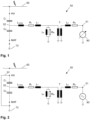
- Fig.1 shows a schematic of a capacitive voltage converter 50, which is coupled to a high-voltage line 60 via a high-voltage connection HV of the voltage converter 50.
- the capacitive voltage converter 50 comprises two capacitors C 1 and C 2 connected in series, which form a voltage divider.
- the first capacitor C 1 is connected to the high-voltage connection HV and the second capacitor C 2 is connected to ground 70 via a connection NHF.
- a tap 52 is provided at the connection between the first capacitor C 1 and the second capacitor C 2 , at which a partial voltage of the high voltage 60 can be tapped during operation of the voltage converter 50.
- the tapped voltage is passed to a primary winding of a transformer T via a compensation inductance L comp .
- a potential-free measuring voltage which is considerably smaller than and proportional to the high voltage on the high-voltage line 60, is available on the secondary winding of the transformer T and can be measured, for example, with a measuring device 80 at a connection 51 on the secondary side of the transformer T.
- the transformer T is shown as an ideal transformer.
- the non-ideal properties of a corresponding real transformer are shown in Fig.1 modelled by a winding resistance R 1 and a leakage inductance L 1 on the primary side, a winding resistance R 2 and a leakage inductance L 2 on the secondary side, a main inductance L h and iron losses R fe .
- the capacitances of the capacitors C 1 and C 2 can be distinguished using different measurements for the analysis of the transfer function (Sweep Frequency Response Analysis, SFRA). These measurements are based on the principle of frequency-dependent short-circuit impedance measurements on the secondary side of the Transformer T. It should be noted that for the measurement according to Fig.4 the NHF terminal must be disconnected from ground. However, this is only possible if the NHF terminal is accessible and can be disconnected from ground. Therefore, it may be advantageous to check the state of the capacitive voltage transformer without measuring according to Fig.4 For all measurements according to the Figures 2 to 4 the high-voltage connection HV of the voltage transformer must be disconnected from the high-voltage line 60.
- SFRA Solep Frequency Response Analysis
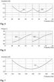
- the high-voltage connection HV is connected to ground 70 via an additional line 91.
- the connection NHF is also connected to ground 70, so that the capacitors C 1 and C 2 are connected in parallel between the tap 52 and ground 70.
- a short-circuit impedance measurement is carried out on the secondary side of the transformer T, i.e. on the low-voltage side of the capacitive voltage converter 50, using a measuring device 90 which is connected to the connection 51 on the secondary side of the transformer T. The short-circuit impedance measurement will be described in detail below.
- the high-voltage connection HV is open and the connection NHF is connected to ground 70.
- the second capacitor C 2 is connected between the tap 52 and ground.
- a short-circuit impedance measurement is carried out on the secondary side of the transformer T using the measuring device 90.
- Fig.4 shows a measuring setup in which the high-voltage connection HV is connected to ground via an additional line 91 and the connection NHF is open, so that essentially only the first capacitor C 1 is connected between the tap 52 and ground 70.
- a short-circuit impedance measurement is carried out on the secondary side of the transformer T using the measuring device 90.
- the Figures 2 to 4 The measurement setups shown differ in that different capacitive loads act on the primary side of the capacitive voltage transformer during the frequency-dependent short-circuit impedance measurement.
- the capacitors C 1 and C 2 are both connected to ground, so that the parallel connection of C 1 and C 2 acts as a capacitive load.
- the capacitor C 2 acts as a capacitive load and in Fig.4 only the capacitor C 1 acts as a capacitive load.
- a capacitance ratio Kc between the capacitance of the capacitor C 1 and the capacitance of the capacitor C 2 can be determined, even without knowledge of the inductive transformation ratio of the capacitive voltage transformer, which is defined by the ratio of the secondary and primary number of turns.
- the frequency-dependent short-circuit impedance measurements are carried out using a current signal which has an amplitude which essentially corresponds to or is close to a nominal current of the capacitive voltage transformer.
- the frequency is gradually changed, for example increased in steps from a low starting frequency to a higher final frequency.
- the current strength of the current signal i.e. a measuring current
- the measuring current can be determined and set based on the load S r and the voltage drop across the load U Sr specified on the nameplate.
- the load can be specified as apparent power in the unit volt-amperes (VA), which is formed as the product of the nominal current occurring on the secondary side of the current transformer and the associated voltage drop across the load.
- VA unit volt-amperes
- a resonance frequency can be determined by several short-circuit impedance measurements at different frequencies.
- the frequency at which a respective short-circuit impedance measurement is carried out can be increased in coarse steps in a first run, so that the range of the resonance frequency can be roughly limited.
- the frequency at which a respective short-circuit impedance measurement is carried out can be increased in finer steps in the range determined in the first run, thus determining the resonance frequency more precisely.
- the first run several short-circuit impedance measurements can be carried out in a first frequency grid
- the second run several short-circuit impedance measurements can be carried out in a second frequency grid that has a smaller frequency spacing than the first frequency grid.
- Resonance frequencies can be used for the Figures 2 to 4
- the resonance frequencies can be used to determine the capacitance ratio.
- three resonance frequencies can be determined from corresponding frequency-dependent short-circuit impedance measurements.
- a first resonance frequency ⁇ e can be determined, which depends on the sum of the capacitances of the capacitors C 1 and C 2 according to equation 2.
- ⁇ e 1 L ⁇ C 1 + C 2
- ⁇ ⁇ e 2 1 L ⁇ C 1 + C 2
- a second resonance frequency ⁇ 2 can be determined, which depends on the capacitance of the capacitor C 2 according to equation 3.
- ⁇ 2 1 L ⁇ C 2
- ⁇ ⁇ 2 2 1 L ⁇ C 2
- the capacitance ratio Kc of the capacitive voltage transformer 50 depends on the individual capacitances of the voltage divider and can be defined as the quotient of the sum of the capacitances of the capacitors C 1 and C 2 and the capacitance of the capacitor C 1 (equation 5), see also International Standard IEC 61869-5, Sec. 3.1.528, Note 501.
- K c C 1 + C 2 C 1
- Equations 2 to 4 derived from the frequency-dependent short-circuit impedance measurements can be used in equation 5.
- equation 6 includes the resonance frequencies ⁇ 1 and ⁇ e
- equation 7 includes the resonance frequencies ⁇ 1 and ⁇ 2
- equation 8 includes the resonance frequencies ⁇ 2 and ⁇ e
- equation 9 includes the resonance frequencies ⁇ 1 , ⁇ 2 and ⁇ e .
- determining the resonance frequency ⁇ 1 can be problematic because this requires disconnecting the NHF connection from ground, which is not always (easily) possible. Therefore, equation 8 will be considered below, which is independent of the measurement of the resonance frequency ⁇ 1 .
- a considerably larger capacitance can be selected for the capacitor C 2 than for the capacitance of the capacitor C 1 , ie, C 2 >>C 1 .
- the total capacitance C 1 +C 2 in the circuit according to Fig.2 differs only slightly from the capacitance of the capacitor C 2 . It follows that the resonance frequencies ⁇ e and ⁇ 2 of the circuits according to Fig.2 and after Fig.3 differ only slightly from each other.
- An inductance which forms a corresponding resonance circuit together with the capacitances C 1 and/or C 2 can have a frequency-dependent non-linearity.
- Equation 8 is the valid equation for determining the capacitance ratio Kc due to the same operating point.
- the resonance inductance L which can be taken into account to consider the capacitances of the capacitors C 1 and C 2 separately, can be derived from the nameplate.
- the resonance inductance L can represent the compensation inductance L comp , the leakage inductances L 1 and L 2 and the main inductance L h .
- the resonance inductance L of the capacitive voltage converter can be determined depending on nominal values of the first and second capacitors C 1 and C 2 and a nominal frequency ⁇ of the capacitive voltage converter.
- the absolute values of the inductance for example the resonance inductance L or the compensation inductance L comp , as well as the absolute values of the capacitors C 1 and C 2 do not necessarily have to be known or of great interest, since they generally have a certain tolerance with respect to the specification on the nameplate. More interesting is the percentage difference of the two capacitances (C 1 and C 2 ) in different measurements over time, i.e. a trend of the ratio of the capacitances to each other.
- both the capacitance ratio Kc and the resonance inductance L of the capacitive voltage converter can be determined using the nominal values given above, for example from the nameplate, independently of the inductive transformation ratio.
- Resonance is achieved in an oscillating circuit when the phase angle between current and voltage reaches a phase angle of 0°. At a phase angle of 0°, inductive and capacitive imaginary components cancel each other out and only the real part remains. The frequency at which this is achieved is called the resonance frequency.
- the resonance inductance L of the capacitive voltage transformer which is important for the separation of C 1 and C 2 , can be derived from frequency-dependent short-circuit impedance measurements. For example, several measurements of the short-circuit impedance can be carried out at different frequencies f over a given frequency range.
- the frequency-dependent short-circuit impedance measurements can be carried out on the secondary side of the capacitive voltage transformer while the high-voltage terminal HV of the first capacitor C 1 is connected to ground, as shown in Fig.2 Alternatively or additionally, the frequency-dependent short-circuit impedance measurements can be carried out on the secondary side of the capacitive voltage transformer while the high-voltage terminal HV of the first capacitor C 1 is open, as shown in Fig.3 These measurements can be considered as measurements on a series resonant circuit. From the measured short-circuit impedances Z sc, a minimum impedance Z sc_f0 , a bandwidth B and a resonance frequency f 0 can be determined.
- the minimum impedance Z sc_f0 is determined by means of the first derivative of the short-circuit impedances Z sc with respect to the frequency f.
- the minimum impedance Z sc_f0 is present where the first derivative of the short-circuit impedance is zero or the phase response has the zero crossing. This point is also referred to as the impedance Z sc_f0 at the resonance frequency f 0.
- This impedance Z sc_f0 corresponds to the ohmic resistance R because the imaginary parts cancel each other out.
- the bandwidth B is also derived from the frequency-dependent short-circuit impedance measurements. The bandwidth B is defined by the -3dB points of the current curve.
- the difference between the resulting upper limit frequency f H and lower limit frequency f L at -3dB is defined as the bandwidth B, i.e. the bandwidth B extends over the frequency range from f L to f H , in which the measured short-circuit current is a maximum of 3dB below the maximum short-circuit current.
- the impedance at the two limit frequencies f L and f H is larger than the impedance Z sc_f0 by a factor of root of 2.
- the values for the resonance inductance L" and resonance capacitance C" in equation 12 refer to the secondary side of the transformer T and are transferred to the primary side using the inductive transformation ratio K IVT of the transformer T, resulting in the resonance inductance L' and the resonance capacitance C' on the primary side of the voltage converter.
- the resonance inductance L' on the primary side determined in this way corresponds to the resonance inductance L, which can be taken into account for the separate consideration of the capacitances of the capacitors C 1 and C 2 and which includes the compensation inductance L comp , the leakage inductances L 1 and L 2 as well as the main inductance L h in the respective circuit according to Fig.2 or according to Fig.3 represents.
- the resonance capacitance C' corresponds to the total capacitance of the first and second capacitors C 1 and C 2 .
- the resonance frequency f 0 or resonance circuit frequency w 0 corresponds to the resonance frequency ⁇ e according to equation 2, taking into account the corresponding resonance inductance L.
- the resonance capacitance C' corresponds to the capacitance of the second capacitor C 2 .
- the resonance frequency f 0 or resonance circuit frequency w 0 corresponds to the resonance frequency ⁇ 2 according to equation 3, taking into account the corresponding resonance inductance L.
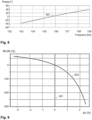
- Fig.5 shows measurement results of short-circuit impedance measurements at different frequencies.
- Fig.5 Impedances 501 from short-circuit impedance measurements on the capacitive voltage transformer according to Fig.2 at different frequencies and impedances 502 of short-circuit impedance measurements on the capacitive voltage transformer according to Fig.3 at different frequencies.
- Fig.6 shows corresponding phase angles which were measured during the short-circuit impedance measurements at different frequencies. Phase angles 601 were measured during the short-circuit impedance measurements on the capacitive voltage transformer according to Fig.2 and phase angle 602 were measured during the short-circuit impedance measurements on the capacitive voltage transformer according to Fig.3 measured.
- the two measurements show a very similar curve of impedance and phase as a function of frequency. Since the capacitance C 2 differs only slightly from the total capacitance C 1 plus C 2 and the resonance frequency is similar, it can be assumed that the same inductance is responsible for the resonance phenomenon in the circuits of the voltage converter according to Fig.2 and Fig.3
- the resonance frequency of the capacitive voltage converter in the circuit according to Fig.2 is in this example between 49 and 50 Hz and the resonance frequency of the capacitive voltage converter in the circuit according to Fig.3 In this example it is between 52 and 53 Hz.
- equation 8 is particularly suitable for considering the capacitance ratio of the capacitive voltage divider, since the operating points of the circuits according to Fig.2 and Fig.3 are almost identical, so the operating points of the non-linear parts of the inductances are almost the same.
- the resonance frequency of the circuit of the capacitive voltage converter is Fig.4 in a significantly different range, as the measurement results of the Figures 7 and 8th show.
- Fig.7 shows the impedance 701 of short-circuit impedance measurements on the capacitive voltage transformer according to Fig.4 at different frequencies and
- Fig.8 shows corresponding phase angles 801, which were measured during the short-circuit impedance measurements at different frequencies. From the Figures 7 and 8th It can be seen that the resonance frequency of the capacitive voltage converter in the circuit according to Fig.4 in the range of 155 to 156 Hz.
- the short-circuit impedance measurements on the capacitive voltage transformer according to the circuits as shown in the Figures 2 and 3 are therefore possible without disconnecting the ground connection at the NHF terminal and can also ensure that the capacitive voltage converter is operated at approximately the same operating point in both cases, so that a non-linear behavior of components of the capacitive voltage converter, for example inductances in the capacitive voltage converter, can be neglected.
- the resonance frequencies can be derived from measurement results of the short-circuit impedance measurements, for example by interpolation.
- the interpolation can have a certain inaccuracy.
- several measurements can be carried out around the phase zero crossing. For example, in a first measurement run, a relatively broad frequency range can be sampled in wide frequency steps, for example a frequency range from 20 Hz to 200 Hz in steps of a few Hertz, for example in steps of 0.5 Hz to 5 Hz. This makes it possible to determine an approximate range in which the resonance frequency is located. The approximate range only covers a few Hertz. In a second measurement run, this range can be sampled in smaller frequency steps, for example in steps of 0.1 Hz or 0.01 Hz, in order to determine the resonance frequency more precisely.
- the capacitance ratio Kc can, for example, be in a range of 10.
- the absolute values of the capacitances of the capacitors C 1 and C 2 can be determined.
- the total inductance of the capacitive voltage converter must be determined.
- the capacitance values from the nameplate of the voltage converter can be used for this.
- the nominal frequency of the capacitive voltage converter can also be specified, for example 50 Hz.
- the inductance of the capacitive voltage converter can be determined at least approximately.
- the capacitance of the capacitor C 1 can be determined using the capacitance of the capacitor C 2 and the capacitance ratio Kc according to equation 16.
- C 1 C 2 K c ⁇ 1
- the deviations of the capacitances of the capacitors C 1 and C 2 thus determined from the values indicated on the nameplate can be determined absolutely or relatively and displayed on a display device of the measuring device 90 in order to assess the condition of the capacitive voltage divider. Reliable operation of the capacitive voltage converter can be assumed, for example, if the actually determined capacitances of the capacitors C 1 and C 2 lie within the tolerance ranges indicated on the nameplate.
- a dependence of the capacitance ratio on the resonance frequency ⁇ e or on the resonance frequency ⁇ 2 can be determined and displayed for an assessment of the condition of the capacitors of the capacitive voltage divider.
- the dependence of the capacitance ratio Kc on the resonance frequency ⁇ 2 can be determined according to equation 17.
- ⁇ K C ⁇ 2 ⁇ 2 ⁇ ⁇ 2 ⁇ ⁇ e 2 ⁇ 2 2 ⁇ ⁇ e 2 2
- Equation 8 the dependence of the capacitance ratio Kc on the resonance frequency ⁇ e can be determined according to equation 18.
- ⁇ K C ⁇ e 2 ⁇ ⁇ 2 2 ⁇ ⁇ e ⁇ 2 2 ⁇ ⁇ e 2 2
- the dependence of the capacitance ratio on the resonance frequency ⁇ e or ⁇ 2 thus relates to a dependence of the change in the capacitance ratio on a change in the resonance frequency ⁇ e or ⁇ 2 .
- This dependence is also referred to as sensitivity.
- a high sensitivity can lead to This helps ensure that even small changes can be clearly detected and thus a deterioration in the condition of the capacitive voltage divider can be detected early and reliably.
- Fig.9 shows the sensitivity of the capacitance ratio Kc with respect to a change in the resonance frequency ⁇ 2 , whereby the representation has been normalized to the measured resonance frequency, i.e.
- the measured resonance frequency is represented by the line 901 and the sensitivity of the capacitance ratio by the graph 902 in percent as a function of the resonance frequency change in percent.
- Fig.10 shows the sensitivity of the capacitance ratio Kc in relation to a change in the resonance frequency ⁇ e .
- This representation has also been normalized to the measured resonance frequency, i.e. the measured resonance frequency is represented by the line 1001 and the sensitivity of the capacitance ratio by the graph 1002 in percent as a function of the resonance frequency change in percent.
- Equation 5 the dependence or sensitivity of the capacitance ratio Kc on the capacitance of the capacitor C 1 can be represented according to equation 20.
- ⁇ K C ⁇ C 1 ⁇ C 2 C 1 2
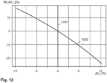
- Fig. 11 shows the sensitivity of the capacitance ratio Kc to a change in the capacitance of the capacitor C 2 .
- the representation has been normalized to the measured resonance frequency, i.e. the measured resonance frequency is represented by the line 1101 and the sensitivity of the capacitance ratio by the graph 1102 in percent depending on the change in the capacitance of the capacitor C 2 in percent.
- Fig. 12 shows the sensitivity of the capacitance ratio Kc to a change in the capacitance of the capacitor C 2 , whereby the representation has been normalized to the measured resonance frequency.
- the measured resonance frequency is represented by the line 1201 and the sensitivity of the capacitance ratio by the graph 1202 in percent as a function of the change in the capacitance of the capacitor C 1 in percent.
- the previously determined procedure can be carried out automatically by the measuring device 90.
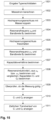
- the operation of the measuring device 90 is summarized below with reference to the Figures 13 to 15 described.
- step 1301 data from the nameplate of the capacitive voltage transformer is entered, for example via a user interface by an operator of the measuring device 90 or with a corresponding scanner which scans the nameplate of the capacitive voltage transformer to be tested.
- the nameplate data can include, for example, the burden and the voltage drop across the burden at nominal frequency as well as nominal values of the first and second capacitors.
- a measuring current is calculated in step 1302, for example as previously described using the burden and the voltage drop across the burden at nominal frequency.
- the high-voltage connection HV is decoupled from the high-voltage line 60 and coupled to ground 70, so that the circuit according to Fig.2 is present.
- the resonance frequency ⁇ e is determined, for example by means of several short-circuit impedance measurements in a first frequency grid followed by several short-circuit impedance measurements in a second frequency grid, the first frequency grid having a larger frequency spacing than the second frequency grid.
- step 1305 the high-voltage connection HV is released so that the circuitry according to Fig.3
- step 1306 the resonance frequency ⁇ 2 is determined by means of short-circuit impedance measurements. Again, several short-circuit impedance measurements in a first frequency grid can be followed of several short-circuit impedance measurements are carried out in a second frequency grid, the first frequency grid having a larger frequency spacing than the second frequency grid.
- step 1307 a capacitance ratio Kc is determined, for example, according to equation 8.
- step 1308 the resonance inductance L is determined from the data on the nameplate, as previously described with reference to equations 10 and 14.
- the capacitance of the capacitor C 2 can be determined according to equation 15 and in step 1310 the capacitance of the capacitor C 1 according to equation 16.
- the capacitance values of the capacitors C 1 and C 2 are displayed on, for example, a display device of the measuring device 90.
- a time trend of the capacitances of the capacitors C 1 and C 2 can be displayed on the display device or, for example, recorded and evaluated in a processing device over a longer period of time. For trend analysis, the capacitances of the capacitors C 1 and C 2 can be recorded over a longer period of time and transferred to a cloud storage, for example.
- step 1401 data from the nameplate of the capacitive voltage transformer is entered.
- This data can be entered, for example, via a user interface by an operator of the measuring device 90.
- this data can be captured electronically from the nameplate of the capacitive voltage transformer to be tested, for example by means of a scanner or a camera.
- the data from the nameplate can include, for example, the burden and the voltage drop across the burden at nominal frequency.
- a suitable measuring current can be calculated in step 1402 (see step 1302).
- the high-voltage connection HV is decoupled from the high-voltage line 60 and coupled to ground 70.
- the circuit of the capacitive voltage converter is therefore Fig.2
- the resonance frequency ⁇ e is determined, for example as previously described using two runs of several short-circuit impedance measurements in different frequency grids.
- the high-voltage connection HV is released so that the circuit of the capacitive voltage converter can be Fig.3 is present.
- the resonance frequency ⁇ 2 is determined, for example also as previously described using two runs of several short-circuit impedance measurements each with different frequency grids.
- a capacitance ratio Kc is determined, for example according to equation 8.
- step 1408 a dependency or sensitivity of the capacitance ratio with respect to the resonance frequency ⁇ 2 is determined (see also equation 17).
- step 1409 a dependency or sensitivity of the capacitance ratio with respect to the resonance frequency ⁇ e is determined (see also equation 18).
- the sensitivities of the capacitance ratio with respect to the resonance frequency ⁇ 2 or ⁇ e are displayed on a display device of the measuring device 90 in step 1410.
- temporal trend curves of the sensitivities of the capacitance ratio in relation to the resonance frequency ⁇ 2 or ⁇ can be displayed or stored over time in order to be evaluated by a processing device. For a trend analysis, the sensitivities can be recorded over a longer period of time and transferred to a cloud storage, for example.
- step 1501 data from the nameplate of the capacitive voltage transformer is entered.
- This data can be entered, for example, via a user interface by an operator of the measuring device 90.
- this data can be recorded electronically from the nameplate of the capacitive voltage transformer to be tested, for example by means of a scanner or a camera.
- the data from the nameplate can include, for example, the load and the voltage drop at the load at nominal frequency as well as an inductive transformation ratio of a transformer of the capacitive voltage transformer.
- a suitable measuring current can be calculated in step 1502 (see step 1302).
- step 1503 the high-voltage connection HV is decoupled from the high-voltage line 60 and coupled to ground 70.
- the circuitry of the capacitive voltage transformer is therefore in accordance with Fig. 2
- step 1504 the resonance frequency ⁇ e and bandwidth B e are determined (see also equation 11), for example as described above using two runs of several short-circuit impedance measurements in different frequency grids.
- step 1505 the high-voltage connection HV is released so that the circuit of the capacitive voltage converter according to Fig.3 is present.
- step 1506 the resonance frequency ⁇ 2 and bandwidth B 2 are determined (see also equation 11), for example also as previously described using two runs of several short-circuit impedance measurements each with different frequency grids.
- a capacitance ratio Kc is determined from the resonance frequencies ⁇ e and ⁇ 2 , for example according to equation 8.
- a respective resonance inductance L is determined from the resonance frequency ⁇ e or ⁇ 2 (see also equation 12). Furthermore, in step 1508, using the respective resonance inductance L, the respective resonance frequency ⁇ e or ⁇ 2 and the inductive transformation ratio, the total capacitance of the capacitors C 1 and C 2 or the capacitance of the capacitor C 2 can be determined according to equation 12. From this, the capacitance of the capacitor C 1 can in turn be determined.
- step 1509 it can be checked whether the measurement is valid by checking that the capacitance ratio Kc determined in step 1507 matches the capacitance ratio of the capacitances of the capacitors C 1 and C 2 determined in step 1508. If the measurement is valid, the capacitance values of the capacitors C 1 and C 2 can be displayed on a display device of the measuring device 90, for example, in step 1510. In addition, in step 1511, a temporal trend of the capacitances of the capacitors C 1 and C 2 can be displayed on the display device or, for example, recorded and evaluated in a processing device over a longer period of time. For a trend analysis, the capacitances of the capacitors C 1 and C 2 can be recorded over a longer period of time and, for example, transferred to a cloud storage.
- the methods described above provide a way to determine and observe a trend of the two capacitances of a capacitive voltage divider in a capacitive voltage converter in order to assess a state of the capacitive voltage converter.
- the trend provides information about the temporal trend of the capacitances of the capacitors C 1 and C 2 in the capacitive voltage divider.
- a temporal change over time is more meaningful than the absolute value of the capacitances. It is therefore justified to use the capacitance values from the nameplate to determine the inductance L of the capacitive voltage transformer, since the absolute accuracy of the capacitance values of the capacitors C 1 and C 2 is not crucial for the trend of the two capacitances.
- the capacitances of the capacitors C 1 and C 2 can be calculated and used as reference values. These values provide a reliable basis for condition monitoring by means of a trend.
Landscapes
- Physics & Mathematics (AREA)
- General Physics & Mathematics (AREA)
- Engineering & Computer Science (AREA)
- Power Engineering (AREA)
- Measurement Of Resistance Or Impedance (AREA)
- Testing Of Short-Circuits, Discontinuities, Leakage, Or Incorrect Line Connections (AREA)
- Testing Relating To Insulation (AREA)
- Measurement Of Current Or Voltage (AREA)
Applications Claiming Priority (2)
| Application Number | Priority Date | Filing Date | Title |
|---|---|---|---|
| AT506072020 | 2020-07-13 | ||
| PCT/EP2021/068482 WO2022012989A1 (de) | 2020-07-13 | 2021-07-05 | Verfahren und vorrichtung zum bestimmen eines zustands eines kapazitiven spannungswandlers |
Publications (3)
| Publication Number | Publication Date |
|---|---|
| EP4158360A1 EP4158360A1 (de) | 2023-04-05 |
| EP4158360B1 true EP4158360B1 (de) | 2024-05-22 |
| EP4158360C0 EP4158360C0 (de) | 2024-05-22 |
Family
ID=76845229
Family Applications (1)
| Application Number | Title | Priority Date | Filing Date |
|---|---|---|---|
| EP21739659.7A Active EP4158360B1 (de) | 2020-07-13 | 2021-07-05 | Verfahren und vorrichtung zum bestimmen eines zustands eines kapazitiven spannungswandlers |
Country Status (12)
| Country | Link |
|---|---|
| US (1) | US12117504B2 (pl) |
| EP (1) | EP4158360B1 (pl) |
| KR (1) | KR102835812B1 (pl) |
| CN (1) | CN115803638B (pl) |
| AU (1) | AU2021307068B2 (pl) |
| BR (1) | BR112022026871A2 (pl) |
| CA (1) | CA3185113C (pl) |
| ES (1) | ES2981845T3 (pl) |
| MX (1) | MX2023000587A (pl) |
| PL (1) | PL4158360T3 (pl) |
| WO (1) | WO2022012989A1 (pl) |
| ZA (1) | ZA202300449B (pl) |
Families Citing this family (4)
| Publication number | Priority date | Publication date | Assignee | Title |
|---|---|---|---|---|
| CN116184296A (zh) * | 2022-12-15 | 2023-05-30 | 国网河北省电力有限公司电力科学研究院 | 直流分压器宽频域传递特性测试系统 |
| KR20250049782A (ko) | 2023-10-05 | 2025-04-14 | 엘지전자 주식회사 | 냉동기의 건전성 지수의 산정 시스템 및 방법 |
| EP4614162A1 (en) * | 2024-03-06 | 2025-09-10 | TE Connectivity Solutions GmbH | Capacitive voltage sensor arrangement having a tuning circuit and voltage sensor system |
| CN119471064B (zh) * | 2024-11-14 | 2025-09-30 | 国网四川省电力公司营销服务中心 | 基于短路频率扫描的电容式电压互感器分压电容测量方法 |
Family Cites Families (23)
| Publication number | Priority date | Publication date | Assignee | Title |
|---|---|---|---|---|
| US2454265A (en) * | 1943-11-06 | 1948-11-16 | Sperry Corp | Automatic frequency control system |
| US2843828A (en) * | 1951-10-18 | 1958-07-15 | Avco Mfg Corp | Ultra-high-frequency converter for very-high-frequency television receiver |
| US3870927A (en) * | 1971-06-08 | 1975-03-11 | English Electric Co Ltd | Capacitor voltage transformer system |
| FR2486326A1 (fr) * | 1980-07-04 | 1982-01-08 | Thomson Brandt | Circuit de commande d'un transistor de commutation dans un convertisseur statique et convertisseur le comportant |
| AU616250B2 (en) | 1988-04-18 | 1991-10-24 | Ergon Energy Corporation Limited | Instrument transformer testing apparatus |
| GB0010720D0 (en) * | 2000-05-03 | 2000-06-28 | Ghassemi Foroozan | Power quality sensors for conventional capacitor coupled voltage transformers |
| RU2248002C2 (ru) | 2003-05-05 | 2005-03-10 | Пензенский государственный университет | Устройство для поверки измерительных трансформаторов напряжения |
| CN100521482C (zh) * | 2006-02-15 | 2009-07-29 | 索尼株式会社 | 开关电源电路 |
| US7567881B2 (en) * | 2007-03-30 | 2009-07-28 | General Electric Company | Self-adjusting voltage filtering technique compensating for dynamic errors of capacitive voltage transformers |
| JP5476524B2 (ja) * | 2009-09-02 | 2014-04-23 | 株式会社明電舎 | 真空コンデンサ形計器用変圧器 |
| JP5463918B2 (ja) * | 2010-01-07 | 2014-04-09 | 大日本印刷株式会社 | 電気部品内蔵基板の電気部品接続検査方法および電気部品内蔵基板 |
| DE102010015906A1 (de) * | 2010-03-10 | 2011-09-15 | Schleifring Und Apparatebau Gmbh | Verfahren zur Kompensation von Systemtoleranzen in induktiven Kopplern |
| WO2014087469A1 (ja) | 2012-12-03 | 2014-06-12 | 三菱電機株式会社 | 電圧検出装置 |
| ES2749449T3 (es) * | 2013-04-05 | 2020-03-20 | Omicron Electronics Gmbh | Método y dispositivo para el ensayo de un transformador |
| CN103364604B (zh) * | 2013-07-30 | 2016-06-29 | 武汉大学 | 适用于高电压谐波测量的电容式电压互感器及测量方法 |
| CN103675445B (zh) * | 2013-12-17 | 2017-01-25 | 国家电网公司 | 一种利用电容式电压互感器进行高压谐波测量的方法 |
| US10260983B2 (en) * | 2014-01-20 | 2019-04-16 | Lear Corporation | Apparatus and method for diagnostics of a capacitive sensor with plausibility check |
| CN104459274A (zh) * | 2014-11-19 | 2015-03-25 | 中国计量科学研究院 | 一种高压标准电容器电压系数的测量方法 |
| US10345363B2 (en) | 2017-09-22 | 2019-07-09 | Schweitzer Engineering Laboratories, Inc. | High-fidelity voltage measurement using resistive divider in a capacitance-coupled voltage transformer |
| EP3544166B1 (de) * | 2018-03-22 | 2022-09-21 | Siemens Aktiengesellschaft | Hilfsversorgung für eine stromversorgung |
| CN108427058A (zh) | 2018-05-30 | 2018-08-21 | 广东电网有限责任公司 | 一种基于同步向量的架空输电线路短路阻抗测量装置 |
| CN108828418A (zh) * | 2018-07-17 | 2018-11-16 | 云南电网有限责任公司红河供电局 | 高压铁磁谐振模拟试验平台 |
| US11650264B2 (en) * | 2019-04-29 | 2023-05-16 | Schweitzer Engineering Laboratories, Inc. | Capacitance-coupled voltage transformer monitoring |
-
2021
- 2021-07-05 PL PL21739659.7T patent/PL4158360T3/pl unknown
- 2021-07-05 US US18/015,899 patent/US12117504B2/en active Active
- 2021-07-05 AU AU2021307068A patent/AU2021307068B2/en active Active
- 2021-07-05 EP EP21739659.7A patent/EP4158360B1/de active Active
- 2021-07-05 KR KR1020237004929A patent/KR102835812B1/ko active Active
- 2021-07-05 CA CA3185113A patent/CA3185113C/en active Active
- 2021-07-05 WO PCT/EP2021/068482 patent/WO2022012989A1/de not_active Ceased
- 2021-07-05 BR BR112022026871A patent/BR112022026871A2/pt unknown
- 2021-07-05 MX MX2023000587A patent/MX2023000587A/es unknown
- 2021-07-05 ES ES21739659T patent/ES2981845T3/es active Active
- 2021-07-05 CN CN202180049167.5A patent/CN115803638B/zh active Active
-
2023
- 2023-01-10 ZA ZA2023/00449A patent/ZA202300449B/en unknown
Also Published As
| Publication number | Publication date |
|---|---|
| US20230305079A1 (en) | 2023-09-28 |
| BR112022026871A2 (pt) | 2023-01-24 |
| MX2023000587A (es) | 2023-02-13 |
| CA3185113A1 (en) | 2022-01-20 |
| PL4158360T3 (pl) | 2024-07-22 |
| AU2021307068B2 (en) | 2024-02-15 |
| EP4158360A1 (de) | 2023-04-05 |
| KR20230047122A (ko) | 2023-04-06 |
| US12117504B2 (en) | 2024-10-15 |
| ZA202300449B (en) | 2024-12-18 |
| WO2022012989A1 (de) | 2022-01-20 |
| CA3185113C (en) | 2025-06-10 |
| CN115803638A (zh) | 2023-03-14 |
| KR102835812B1 (ko) | 2025-07-21 |
| EP4158360C0 (de) | 2024-05-22 |
| ES2981845T3 (es) | 2024-10-10 |
| CN115803638B (zh) | 2025-11-18 |
| AU2021307068A1 (en) | 2023-02-09 |
Similar Documents
| Publication | Publication Date | Title |
|---|---|---|
| EP4158360B1 (de) | Verfahren und vorrichtung zum bestimmen eines zustands eines kapazitiven spannungswandlers | |
| EP2787357B1 (de) | Verfahren und Vorrichtung zum Testen eines Transformators | |
| DE102013014175B4 (de) | Verfahren zur Kalibrierung eines Messaufbaus | |
| EP1304580A2 (de) | Verfahren zur Berechnung der Distanz zum Fehlerort eines einpoligen Erdfehlers in einem Energieversorgungsnetz | |
| EP3862763A1 (de) | Verfahren zur überwachung eines erdwiderstands einer elektrischen anlage | |
| EP3069359B1 (de) | Verfahren und vorrichtung zur überwachung von kondensatordurchführungen für ein dreiphasiges wechselstromnetz | |
| DE102006009040A1 (de) | Koaxialkabel und Testverfahren für ein Koaxialkabel | |
| DE10107441A1 (de) | Verfahren zum Charakterisieren von Frequenzumsetzungsvorrichtungen | |
| AT523525A4 (de) | Elektrische Schaltungsanordnung | |
| DE19722471C2 (de) | Impedanz- und Strommeßeinrichtung | |
| EP3102961B1 (de) | Zeitbereichsmessverfahren mit kalibrierung im frequenzbereich | |
| EP3870983B1 (de) | Zustandsanalyse eines elektrischen betriebsmittels | |
| DE19545267A1 (de) | Verfahren zum Gewinnen von fehlerbehaftete Schleifen in einem mehrphasigen elektrischen Energieversorgungsnetz kennzeichnenden Signalen | |
| DE69326567T2 (de) | Schaltkreise zur Verwendung bei Feststellung und Ortung eines Fehlers oder von Fehlern in einer zu testenden Anordnung | |
| DE3709532A1 (de) | Verfahren zur pruefung von anordnungen | |
| DE4418124C2 (de) | Vorrichtung zum Erkennen einer Isolationsverschlechterung an Stromversorgungsleitungen | |
| DE2647346C3 (de) | Verfahren zur Überwachung des Isolationszustandes der Phasen eines ein- oder mehrphasigen Geräts und Anordnung zur Durchführung des Verfahrens | |
| DE102024202219A1 (de) | Vorrichtung und Verfahren zur Analyse von Störgrößen eines elektronischen Geräts | |
| EP2093577B1 (de) | Verfahren und Vorrichtung zum Prüfen einer energietechnischen Einrichtung | |
| DE102018106493A1 (de) | Schutzschaltung für oszilloskopmesskanal | |
| DE102023120271B4 (de) | Vorrichtung zum Überwachen eines Versorgungsnetzes | |
| AT525068B1 (de) | Verfahren und Vorrichtung zum Prüfen eines Spannungswandlers | |
| DE102013213296B4 (de) | Verfahren und Messgerät zum Charakterisieren eines emittierenden Messobjekts | |
| WO2020151986A1 (de) | Überprüfen von mantelspannungsbegrenzern | |
| DE102019126438A1 (de) | Kompensationsvorrichtung für Ableitströme |
Legal Events
| Date | Code | Title | Description |
|---|---|---|---|
| STAA | Information on the status of an ep patent application or granted ep patent |
Free format text: STATUS: UNKNOWN |
|
| STAA | Information on the status of an ep patent application or granted ep patent |
Free format text: STATUS: THE INTERNATIONAL PUBLICATION HAS BEEN MADE |
|
| PUAI | Public reference made under article 153(3) epc to a published international application that has entered the european phase |
Free format text: ORIGINAL CODE: 0009012 |
|
| STAA | Information on the status of an ep patent application or granted ep patent |
Free format text: STATUS: REQUEST FOR EXAMINATION WAS MADE |
|
| 17P | Request for examination filed |
Effective date: 20221228 |
|
| AK | Designated contracting states |
Kind code of ref document: A1 Designated state(s): AL AT BE BG CH CY CZ DE DK EE ES FI FR GB GR HR HU IE IS IT LI LT LU LV MC MK MT NL NO PL PT RO RS SE SI SK SM TR |
|
| P01 | Opt-out of the competence of the unified patent court (upc) registered |
Effective date: 20230412 |
|
| DAV | Request for validation of the european patent (deleted) | ||
| DAX | Request for extension of the european patent (deleted) | ||
| GRAP | Despatch of communication of intention to grant a patent |
Free format text: ORIGINAL CODE: EPIDOSNIGR1 |
|
| STAA | Information on the status of an ep patent application or granted ep patent |
Free format text: STATUS: GRANT OF PATENT IS INTENDED |
|
| INTG | Intention to grant announced |
Effective date: 20240130 |
|
| GRAS | Grant fee paid |
Free format text: ORIGINAL CODE: EPIDOSNIGR3 |
|
| GRAA | (expected) grant |
Free format text: ORIGINAL CODE: 0009210 |
|
| STAA | Information on the status of an ep patent application or granted ep patent |
Free format text: STATUS: THE PATENT HAS BEEN GRANTED |
|
| AK | Designated contracting states |
Kind code of ref document: B1 Designated state(s): AL AT BE BG CH CY CZ DE DK EE ES FI FR GB GR HR HU IE IS IT LI LT LU LV MC MK MT NL NO PL PT RO RS SE SI SK SM TR |
|
| REG | Reference to a national code |
Ref country code: GB Ref legal event code: FG4D Free format text: NOT ENGLISH |
|
| REG | Reference to a national code |
Ref country code: CH Ref legal event code: EP |
|
| REG | Reference to a national code |
Ref country code: DE Ref legal event code: R096 Ref document number: 502021003812 Country of ref document: DE |
|
| REG | Reference to a national code |
Ref country code: IE Ref legal event code: FG4D Free format text: LANGUAGE OF EP DOCUMENT: GERMAN |
|
| U01 | Request for unitary effect filed |
Effective date: 20240612 |
|
| U07 | Unitary effect registered |
Designated state(s): AT BE BG DE DK EE FI FR IT LT LU LV MT NL PT SE SI Effective date: 20240624 |
|
| P04 | Withdrawal of opt-out of the competence of the unified patent court (upc) registered |
Free format text: CASE NUMBER: APP_36719/2024 Effective date: 20240619 |
|
| U20 | Renewal fee for the european patent with unitary effect paid |
Year of fee payment: 4 Effective date: 20240726 |
|
| PG25 | Lapsed in a contracting state [announced via postgrant information from national office to epo] |
Ref country code: IS Free format text: LAPSE BECAUSE OF FAILURE TO SUBMIT A TRANSLATION OF THE DESCRIPTION OR TO PAY THE FEE WITHIN THE PRESCRIBED TIME-LIMIT Effective date: 20240922 |
|
| PG25 | Lapsed in a contracting state [announced via postgrant information from national office to epo] |
Ref country code: HR Free format text: LAPSE BECAUSE OF FAILURE TO SUBMIT A TRANSLATION OF THE DESCRIPTION OR TO PAY THE FEE WITHIN THE PRESCRIBED TIME-LIMIT Effective date: 20240522 |
|
| REG | Reference to a national code |
Ref country code: ES Ref legal event code: FG2A Ref document number: 2981845 Country of ref document: ES Kind code of ref document: T3 Effective date: 20241010 |
|
| PG25 | Lapsed in a contracting state [announced via postgrant information from national office to epo] |
Ref country code: GR Free format text: LAPSE BECAUSE OF FAILURE TO SUBMIT A TRANSLATION OF THE DESCRIPTION OR TO PAY THE FEE WITHIN THE PRESCRIBED TIME-LIMIT Effective date: 20240823 |
|
| PG25 | Lapsed in a contracting state [announced via postgrant information from national office to epo] |
Ref country code: NO Free format text: LAPSE BECAUSE OF FAILURE TO SUBMIT A TRANSLATION OF THE DESCRIPTION OR TO PAY THE FEE WITHIN THE PRESCRIBED TIME-LIMIT Effective date: 20240822 Ref country code: IS Free format text: LAPSE BECAUSE OF FAILURE TO SUBMIT A TRANSLATION OF THE DESCRIPTION OR TO PAY THE FEE WITHIN THE PRESCRIBED TIME-LIMIT Effective date: 20240922 Ref country code: HR Free format text: LAPSE BECAUSE OF FAILURE TO SUBMIT A TRANSLATION OF THE DESCRIPTION OR TO PAY THE FEE WITHIN THE PRESCRIBED TIME-LIMIT Effective date: 20240522 Ref country code: GR Free format text: LAPSE BECAUSE OF FAILURE TO SUBMIT A TRANSLATION OF THE DESCRIPTION OR TO PAY THE FEE WITHIN THE PRESCRIBED TIME-LIMIT Effective date: 20240823 Ref country code: RS Free format text: LAPSE BECAUSE OF FAILURE TO SUBMIT A TRANSLATION OF THE DESCRIPTION OR TO PAY THE FEE WITHIN THE PRESCRIBED TIME-LIMIT Effective date: 20240822 |
|
| P05 | Withdrawal of opt-out of the competence of the unified patent court (upc) changed |
Free format text: CASE NUMBER: APP_36719/2024 Effective date: 20240624 |
|
| PG25 | Lapsed in a contracting state [announced via postgrant information from national office to epo] |
Ref country code: CZ Free format text: LAPSE BECAUSE OF FAILURE TO SUBMIT A TRANSLATION OF THE DESCRIPTION OR TO PAY THE FEE WITHIN THE PRESCRIBED TIME-LIMIT Effective date: 20240522 |
|
| PG25 | Lapsed in a contracting state [announced via postgrant information from national office to epo] |
Ref country code: SK Free format text: LAPSE BECAUSE OF FAILURE TO SUBMIT A TRANSLATION OF THE DESCRIPTION OR TO PAY THE FEE WITHIN THE PRESCRIBED TIME-LIMIT Effective date: 20240522 Ref country code: RO Free format text: LAPSE BECAUSE OF FAILURE TO SUBMIT A TRANSLATION OF THE DESCRIPTION OR TO PAY THE FEE WITHIN THE PRESCRIBED TIME-LIMIT Effective date: 20240522 |
|
| PG25 | Lapsed in a contracting state [announced via postgrant information from national office to epo] |
Ref country code: SK Free format text: LAPSE BECAUSE OF FAILURE TO SUBMIT A TRANSLATION OF THE DESCRIPTION OR TO PAY THE FEE WITHIN THE PRESCRIBED TIME-LIMIT Effective date: 20240522 Ref country code: RO Free format text: LAPSE BECAUSE OF FAILURE TO SUBMIT A TRANSLATION OF THE DESCRIPTION OR TO PAY THE FEE WITHIN THE PRESCRIBED TIME-LIMIT Effective date: 20240522 Ref country code: CZ Free format text: LAPSE BECAUSE OF FAILURE TO SUBMIT A TRANSLATION OF THE DESCRIPTION OR TO PAY THE FEE WITHIN THE PRESCRIBED TIME-LIMIT Effective date: 20240522 |
|
| PG25 | Lapsed in a contracting state [announced via postgrant information from national office to epo] |
Ref country code: MC Free format text: LAPSE BECAUSE OF FAILURE TO SUBMIT A TRANSLATION OF THE DESCRIPTION OR TO PAY THE FEE WITHIN THE PRESCRIBED TIME-LIMIT Effective date: 20240522 |
|
| REG | Reference to a national code |
Ref country code: DE Ref legal event code: R097 Ref document number: 502021003812 Country of ref document: DE |
|
| PLBE | No opposition filed within time limit |
Free format text: ORIGINAL CODE: 0009261 |
|
| STAA | Information on the status of an ep patent application or granted ep patent |
Free format text: STATUS: NO OPPOSITION FILED WITHIN TIME LIMIT |
|
| 26N | No opposition filed |
Effective date: 20250225 |
|
| PGFP | Annual fee paid to national office [announced via postgrant information from national office to epo] |
Ref country code: PL Payment date: 20250612 Year of fee payment: 5 |
|
| PG25 | Lapsed in a contracting state [announced via postgrant information from national office to epo] |
Ref country code: IE Free format text: LAPSE BECAUSE OF NON-PAYMENT OF DUE FEES Effective date: 20240705 |
|
| U20 | Renewal fee for the european patent with unitary effect paid |
Year of fee payment: 5 Effective date: 20250729 |
|
| PGFP | Annual fee paid to national office [announced via postgrant information from national office to epo] |
Ref country code: ES Payment date: 20250808 Year of fee payment: 5 |
|
| PGFP | Annual fee paid to national office [announced via postgrant information from national office to epo] |
Ref country code: TR Payment date: 20250702 Year of fee payment: 5 |
|
| PGFP | Annual fee paid to national office [announced via postgrant information from national office to epo] |
Ref country code: GB Payment date: 20250725 Year of fee payment: 5 |
|
| PGFP | Annual fee paid to national office [announced via postgrant information from national office to epo] |
Ref country code: CH Payment date: 20250807 Year of fee payment: 5 |
|
| PG25 | Lapsed in a contracting state [announced via postgrant information from national office to epo] |
Ref country code: CY Free format text: LAPSE BECAUSE OF FAILURE TO SUBMIT A TRANSLATION OF THE DESCRIPTION OR TO PAY THE FEE WITHIN THE PRESCRIBED TIME-LIMIT; INVALID AB INITIO Effective date: 20210705 |
|
| PG25 | Lapsed in a contracting state [announced via postgrant information from national office to epo] |
Ref country code: SM Free format text: LAPSE BECAUSE OF FAILURE TO SUBMIT A TRANSLATION OF THE DESCRIPTION OR TO PAY THE FEE WITHIN THE PRESCRIBED TIME-LIMIT; INVALID AB INITIO Effective date: 20210705 |
|
| PG25 | Lapsed in a contracting state [announced via postgrant information from national office to epo] |
Ref country code: HU Free format text: LAPSE BECAUSE OF FAILURE TO SUBMIT A TRANSLATION OF THE DESCRIPTION OR TO PAY THE FEE WITHIN THE PRESCRIBED TIME-LIMIT; INVALID AB INITIO Effective date: 20210705 |