EP4158111B1 - Ein mit einem dichtungshalter versehene verstärkungselement für stützwände - Google Patents
Ein mit einem dichtungshalter versehene verstärkungselement für stützwände Download PDFInfo
- Publication number
- EP4158111B1 EP4158111B1 EP21728210.2A EP21728210A EP4158111B1 EP 4158111 B1 EP4158111 B1 EP 4158111B1 EP 21728210 A EP21728210 A EP 21728210A EP 4158111 B1 EP4158111 B1 EP 4158111B1
- Authority
- EP
- European Patent Office
- Prior art keywords
- seal
- reinforcement
- trench
- sacrificial material
- carrier
- Prior art date
- Legal status (The legal status is an assumption and is not a legal conclusion. Google has not performed a legal analysis and makes no representation as to the accuracy of the status listed.)
- Active
Links
Images





Classifications
-
- E—FIXED CONSTRUCTIONS
- E02—HYDRAULIC ENGINEERING; FOUNDATIONS; SOIL SHIFTING
- E02D—FOUNDATIONS; EXCAVATIONS; EMBANKMENTS; UNDERGROUND OR UNDERWATER STRUCTURES
- E02D5/00—Bulkheads, piles, or other structural elements specially adapted to foundation engineering
- E02D5/18—Bulkheads or similar walls made solely of concrete in situ
- E02D5/185—Bulkheads or similar walls made solely of concrete in situ with flexible joint members between sections
-
- E—FIXED CONSTRUCTIONS
- E02—HYDRAULIC ENGINEERING; FOUNDATIONS; SOIL SHIFTING
- E02D—FOUNDATIONS; EXCAVATIONS; EMBANKMENTS; UNDERGROUND OR UNDERWATER STRUCTURES
- E02D5/00—Bulkheads, piles, or other structural elements specially adapted to foundation engineering
- E02D5/20—Bulkheads or similar walls made of prefabricated parts and concrete, including reinforced concrete, in situ
-
- E—FIXED CONSTRUCTIONS
- E04—BUILDING
- E04C—STRUCTURAL ELEMENTS; BUILDING MATERIALS
- E04C5/00—Reinforcing elements, e.g. for concrete; Auxiliary elements therefor
- E04C5/01—Reinforcing elements of metal, e.g. with non-structural coatings
- E04C5/06—Reinforcing elements of metal, e.g. with non-structural coatings of high bending resistance, i.e. of essentially three-dimensional [3D] extent, e.g. lattice girders
-
- E—FIXED CONSTRUCTIONS
- E04—BUILDING
- E04C—STRUCTURAL ELEMENTS; BUILDING MATERIALS
- E04C5/00—Reinforcing elements, e.g. for concrete; Auxiliary elements therefor
- E04C5/01—Reinforcing elements of metal, e.g. with non-structural coatings
- E04C5/06—Reinforcing elements of metal, e.g. with non-structural coatings of high bending resistance, i.e. of essentially three-dimensional [3D] extent, e.g. lattice girders
- E04C5/0604—Prismatic or cylindrical reinforcement cages composed of longitudinal bars and open or closed stirrup rods
-
- E—FIXED CONSTRUCTIONS
- E04—BUILDING
- E04C—STRUCTURAL ELEMENTS; BUILDING MATERIALS
- E04C5/00—Reinforcing elements, e.g. for concrete; Auxiliary elements therefor
- E04C5/01—Reinforcing elements of metal, e.g. with non-structural coatings
- E04C5/06—Reinforcing elements of metal, e.g. with non-structural coatings of high bending resistance, i.e. of essentially three-dimensional [3D] extent, e.g. lattice girders
- E04C5/0604—Prismatic or cylindrical reinforcement cages composed of longitudinal bars and open or closed stirrup rods
- E04C5/0609—Closed cages composed of two or more coacting cage parts, e.g. transversally hinged or nested parts
-
- E—FIXED CONSTRUCTIONS
- E02—HYDRAULIC ENGINEERING; FOUNDATIONS; SOIL SHIFTING
- E02D—FOUNDATIONS; EXCAVATIONS; EMBANKMENTS; UNDERGROUND OR UNDERWATER STRUCTURES
- E02D2250/00—Production methods
- E02D2250/0023—Cast, i.e. in situ or in a mold or other formwork
-
- E—FIXED CONSTRUCTIONS
- E02—HYDRAULIC ENGINEERING; FOUNDATIONS; SOIL SHIFTING
- E02D—FOUNDATIONS; EXCAVATIONS; EMBANKMENTS; UNDERGROUND OR UNDERWATER STRUCTURES
- E02D2300/00—Materials
- E02D2300/0004—Synthetics
- E02D2300/0018—Cement used as binder
- E02D2300/002—Concrete
-
- E—FIXED CONSTRUCTIONS
- E02—HYDRAULIC ENGINEERING; FOUNDATIONS; SOIL SHIFTING
- E02D—FOUNDATIONS; EXCAVATIONS; EMBANKMENTS; UNDERGROUND OR UNDERWATER STRUCTURES
- E02D2300/00—Materials
- E02D2300/0026—Metals
- E02D2300/0029—Steel; Iron
- E02D2300/0034—Steel; Iron in wire form
-
- E—FIXED CONSTRUCTIONS
- E02—HYDRAULIC ENGINEERING; FOUNDATIONS; SOIL SHIFTING
- E02D—FOUNDATIONS; EXCAVATIONS; EMBANKMENTS; UNDERGROUND OR UNDERWATER STRUCTURES
- E02D2600/00—Miscellaneous
- E02D2600/20—Miscellaneous comprising details of connection between elements
Definitions
- the invention relates to the field of manufacturing diaphragm walls in the ground. It relates in particular to the techniques for joining two adjacent panels of the diaphragm wall.
- a diaphragm wall consists of a plurality of adjacent panels, connected one after the other. To ensure continuity and watertightness between two adjacent panels, it is important that the junction between the panels is correctly made.
- the first panel is towed so that the concrete of the second panel will come into contact with the concrete of the first panel in order to ensure the continuity of concrete between the two panels.
- a second technique involves using formwork, usually metal, which is temporarily inserted into the trench and removed after the concrete has hardened.
- This formwork allows for the installation of a waterproof joint that extends vertically along the end edge of the panel.
- Such a technique is notably described in EP 0 101 350
- the use of formwork makes the second technique more expensive and time-consuming than the first technique.
- An aim of the present invention is to make it possible to make a junction between two adjacent panels without using formwork.
- the invention relates to a reinforcement element for a diaphragm wall according to claim 1 comprising a reinforcement cage which has a length defining a longitudinal direction, a width and a thickness, the reinforcement cage having a first end portion and a second end portion opposite the first end portion, the first and second end portions extending in the longitudinal direction of the reinforcement cage, the reinforcement element further comprising at least one seal holder provided with a mounting portion for receiving at least one sealing gasket which is elongate, the seal holder being fixed to the first end portion of the reinforcement cage and extending in the longitudinal direction of said reinforcement cage, the reinforcement element is characterized in that said seal holder comprises two wings extending in the longitudinal direction and a bottom so as to define a housing for receiving the sealing gasket, at least a first portion of which is surrounded by a sacrificial material.
- the reinforcing element according to the invention therefore makes it possible both to reinforce the concrete constituting the panel, and to place and fix the sealing joint along the first vertical edge of the panel, without using a formwork element.
- the reinforcement element according to the invention is placed in a first trench before pouring the concrete.
- the second trench is drilled and then the sacrificial material is removed so as to expose the first part of the seal, the second part of the seal being engaged in the concrete of the first panel.
- This first part of the seal will then be embedded in the concrete when pouring concrete into the second trench.
- the first part will be embedded in the concrete of the second panel adjacent to the first panel, so as to create a seal between the first and second panels.
- seal is intended to be arranged in the housing. Without departing from the scope of the present invention, the seal holder can receive several seals arranged side by side.
- the reinforcement cage comprises a plurality of reinforcement rods, so as to produce reinforced concrete.
- the wings of the housing flank the sacrificial material, in order to protect it, in particular when introducing the reinforcement element into the trench.
- the distance between the wings is less than the width of the reinforcement cage, more preferably, this distance is less than half the width of the reinforcement cage.
- the wings are parallel.
- the sealing gasket is fixed to the bottom of the housing.
- the joint holder is preferably a longitudinal profile. It extends along the height of the reinforcement cage.
- the longitudinal profile has a “U” section.
- the longitudinal profile consists of two longitudinal “L”-shaped elements.
- the two longitudinal “L”-shaped elements are spaced apart from each other in order to form a slot into which the sealing gasket is inserted.
- the longitudinal profile is fixed, for example by welding, to the reinforcement cage, preferably to its first end part.
- the joint holder may be mounted at least partly in the volume of the reinforcement cage.
- the joint holder may be located in a recess of the reinforcement cage.
- the mounting part comprises a longitudinal slot provided in the bottom to receive the sealing gasket.
- the sealing joint has a length which is greater than the length of the longitudinal slot of a reinforcement element.
- the length of the sealing joint is greater than the length of the joint holder.
- the sealing joint is successively engaged in the slots of the joint holders of several reinforcement elements arranged vertically above each other in the trench. Such an assembly makes it possible to ensure the vertical continuity of the sealing.
- the reinforcement element further comprises at least one reinforcing member connecting at least one of the wings to the reinforcement cage.
- the reinforcing members have the effect of increasing the robustness of the attachment of the joint holder to the reinforcement cage.
- the reinforcement cage considered in a plane perpendicular to the longitudinal direction, comprises two adjacent reinforcement portions each provided with at least two parallel reinforcements, the joint holder being fixed to each of the two adjacent reinforcement portions.
- the joint holder is arranged between the two adjacent reinforcement portions. The two adjacent reinforcement portions are also fixed to each other by means of fixing means separate from the joint holder.
- the invention further relates to a reinforcement device comprising a reinforcement element according to the invention, as well as at least one seal and a sacrificial material in the housing, the seal being mounted on the seal holder while being at least partly bordered by the sacrificial material.
- the sacrificial material is disposed in the housing, on either side of the seal. More specifically, the sacrificial material is disposed on either side of the first portion of the seal that is in the housing. More preferably, the sacrificial material substantially fills the volume of the housing.
- One advantage is to prevent concrete from adhering to the first portion of the seal that is in the housing.
- the span i.e. the maximum thickness of the sacrificial material, is less than the thickness of the reinforcement cage.
- the seal further has a second part, the first and second parts being arranged on either side of the bottom when the seal is mounted on the seal holder, so that the seal extends transversely on either side of the bottom, the first part being located in the housing and flanked by the sacrificial material.
- the first part of the seal is located entirely within the volume of the housing.
- the sacrificial material is a friable material. It preferably comprises polystyrene.
- the invention finally relates to a method of producing according to claim 10 a cast wall in a ground in which a first vertical trench in the ground, a first reinforcement device according to the invention is placed in the first trench, concrete is poured into the first trench and then, after the concrete has hardened, a second vertical trench is drilled in the ground, juxtaposed with the first trench on the side of the joint holder, the sacrificial material is removed from the housing using the scraper tool according to the invention, so that the first part of the sealing joint extends into the second trench, then concrete is placed in the second trench.
- the scraper tool comprises two parallel teeth spaced apart from each other so as to define a passage for the seal.
- the width of the scraper tool is substantially equal to the distance between the wings of the seal holder.
- the teeth are engaged in the housing, on either side of the first part of the seal.
- the scraper tool is placed in the housing while engaging the first part of the seal in the passage between the two teeth of the scraper tool.
- the vertical movement of the teeth has the effect of removing the sacrificial material from the housing.
- the teeth Preferably, the teeth have a face inclined relative to the bottom so as to facilitate the removal of the sacrificial material.
- the first panel is obtained, which includes the reinforcement element.
- the second part of the joint seal is engaged with the concrete of the first panel. After removing the sacrificial material from the housing, the first part of the seal is uncovered.
- the housing then opens onto the second trench. When concrete is placed in the second trench, the concrete flows into the housing so that the first part of the seal engages with the concrete of the second trench.
- the first panel can be towed if necessary when drilling the second adjacent trench, in order to clear the ground between the second trench and the accommodation.
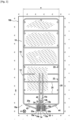
- This reinforcement device comprises a reinforcement element 12 for a diaphragm wall in accordance with the invention, as well as a sealing joint 14 and a sacrificial material 16 which will be described in more detail below.
- the reinforcement element 12 comprises a reinforcement cage 18 which is made up of a plurality of horizontal 20 and vertical 22 bars which are fixed to each other, for example by welding, in a manner known elsewhere.
- the reinforcement cage 18 has a length L defining a longitudinal direction, which is generally vertical. This length can also be considered as being the height of the reinforcement cage.
- the reinforcement cage 18 also has a width l and a thickness e visible in Figure 2 .
- the reinforcement cage 18 has, considered according to its width, a first end portion 18 a and a second end portion 18 b opposite the first end portion 18 a.
- the first and second end portions 18a, 18b extend vertically along the longitudinal direction A of the reinforcement cage.
- the seal 14 is longer than the length of the reinforcement cage.
- the reinforcement element 18 further comprises a seal holder 30 located at the first end portion 18a of the reinforcement element 18.
- the seal holder 30 is designed to receive the sealing gasket 14. Without departing from the scope of the invention, the seal holder 30 could receive several sealing gaskets arranged side by side.
- the joint holder 30 is fixed to the first end portion 18a of the reinforcement cage 18.
- the joint holder 30 also extends in the longitudinal direction A of the reinforcement cage.
- the joint holder 30 comprises two wings 30a, 30b separated by a distance d.
- the two wings are parallel and extend in the longitudinal direction A. When they are parallel, this facilitates the guidance of the scraper tool which will be described below.
- the distance d between the flanges of the joint holder is less than the thickness of the reinforcement cage, and more precisely less than half the thickness e of the reinforcement cage 18.
- the seal holder 30 further comprises a bottom 34 which, in this example, is perpendicular to the wings 30a , 30b .
- the bottom also extends in the longitudinal direction.
- the two wings and the bottom thus define a housing 36 for receiving the elongate sealing gasket 14.
- the seal holder 30 is a longitudinal profile, which has a “U” section, considered in a horizontal plane.
- the longitudinal profile is made up of two longitudinal elements 31a, 31b in an “L” shape. These two longitudinal elements are spaced apart from each other so as to delimit a longitudinal slot 40, this longitudinal slot being formed in the bottom 14 and constituting a mounting part 32 for receiving the sealing joint 14.
- the seal holder 30 is fixed, for example by welding, to reinforcement bars 20 a which constitute the first end part 18 a of the reinforcement cage 18.
- the sealing joint 14 is flat and comprises two lateral beads 15 a, 15 b and a central bead 15 c, the lateral beads and the central bead being parallel and extending along the length of the sealing joint 14.
- the first part of the seal is surrounded by the sacrificial material 16, while its second part 14 b extends inside the volume of the reinforcement cage.
- the seal extends on either side of the first end part 18 a of the reinforcement cage 18.
- the seal 14 also extends on either side of the bottom 34, perpendicular to said bottom 34.
- the span of the sacrificial material is strictly less than the thickness e of the reinforcement cage, and moreover less than half the width of the reinforcement cage.
- the reinforcement element 12 further comprises reinforcing members 42, 44 which connect the wings 30a, 30b of the joint holder to the reinforcement cage 18.
- these are metal rods which are welded to the wings on the one hand and to the reinforcement cage on the other hand.
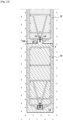
- the reinforcement cage 18, considered in a plane perpendicular to the longitudinal direction A, that is to say in a horizontal plane, comprises two reinforcement portions 19, 21 which are adjacent and which are each provided with at least two parallel rods 23, 25.
- the joint holder is fixed to each of the two adjacent reinforcement parts 19, 21. More precisely, the wings 30a, 30b of the joint holder are fixed to the parallel rods 23, 25. Also, in this embodiment, it is not necessary to provide reinforcing members. It can be seen that in this embodiment, the joint holder is engaged in a recess made in the reinforcement cage 18, this recess being delimited laterally by the parallel rods 23, 25.
- first and second parts 14a, 14b of the seal are arranged on either side of the bottom 34 when the seal is mounted on the seal holder 30, so that the seal 14 extends transversely relative to the bottom 34, the first part being located in the housing and flanked by the sacrificial material.
- the seal 14 is arranged in the volume of the reinforcement cage 18.
- the sacrificial material 16 comprises polystyrene. More generally, the sacrificial material is friable. In this example, the sacrificial material 16 consists of two blocks 16 a, 16 b which flank the first part 14 a of the seal 14.
- a scraper tool 100 illustrated in Figure 6
- the scraper tool 100 is attached to a frame 102 which is vertically movable by suitable means known elsewhere and not illustrated here .
- the scraper tool can be attached to one side of the frame of a bucket-type drilling tool.
- the scraper tool 100 comprises two teeth 104, 106 which are parallel to each other while being spaced apart from each other so as to define between them a passage 109 for the seal 14.
- the width of the passage 109 is slightly greater than the thickness of the seal.
- the width q of the scraper tool is substantially equal to the distance between the wings 30a, 30b of the seal holder 30.
- the two teeth 104, 106 are, in this example, fixed to a plate 108 which is itself fixed to the chassis 102.
- the end of the teeth 104, 106 is beveled so as to facilitate the evacuation of the polystyrene from the housing 36.
- drilling is carried out while filling the trench with mud in order to prevent the trench walls from collapsing.
- the trench has a length a and a width b. It has first and second vertical walls 200, 202 opposite each other, and third and fourth vertical walls 204, 206 opposite each other. In this example, the first and second vertical walls 200, 202 are smaller than the third and fourth vertical walls 204, 206.
- a first reinforcement device 10 according to the invention is placed in the first trench T1 , for example that of the example of the Figure 2 .
- the reinforcement device 10 is placed in the trench T1 in such a way that the joint holder 30 is opposite the first wall 200.
- the first end part of the device 18 a of the reinforcement cage 18, constituted by the opening 37 of the housing 36 is distant, considered in a horizontal plane, from the first wall 200 of the trench T1.
- This distance is referenced X.
- this distance X should be as small as possible, if possible equal to or close to zero. In this example, this distance is of the order of 10 cm.
- the reinforcement device 10 could be placed in the trench so that the joint holder 30 comes to bear against the first wall 200 of the trench T1.
- a second vertical trench T2 is drilled in the ground S , this second trench T2 being juxtaposed with the first vertical trench T1 on the side of the joint holder 30.
- the drilling is carried out using a drilling tool represented by the reference 300, the drilling tool 300 being placed as close as possible to the seal holder 30.
- the first panel 250 is illustrated, obtained after hardening of the concrete in the first trench T1, and towed over part of its length in order to reach the joint holder 30 or at least to minimize the thickness of residual concrete between the joint holder and the second trench T2.
- the result is illustrated in Figure 11 .
- the sacrificial material 16 comes into contact with the mud of the second trench T2.
- the scraper tool 100 is engaged in the housing at the top of the seal holder 30 so that the seal 14 is arranged in the passage 109 located between the teeth 104, 106.
- each of the teeth 104, 106 is located between the first part 14 a of the seal and one or other of the wings 30a, 30b of the seal holder 30, so as to be engaged in the volume which is occupied by the sacrificial material. It is understood that the descent along the vertical axis Z of the scraper tool 100 has the effect of evacuating the sacrificial material towards the second trench T2.
- the housing is opened in the second trench T2 so that the mud fills the housing.
- the first part 14a of the seal 14 is then surrounded by mud.
- a second reinforcement device 10' is placed, then concrete is placed in the second trench T2 so as to obtain, after hardening, the second panel 252.
Landscapes
- Engineering & Computer Science (AREA)
- Architecture (AREA)
- Structural Engineering (AREA)
- Civil Engineering (AREA)
- General Life Sciences & Earth Sciences (AREA)
- Paleontology (AREA)
- Mining & Mineral Resources (AREA)
- General Engineering & Computer Science (AREA)
- Life Sciences & Earth Sciences (AREA)
- Reinforcement Elements For Buildings (AREA)
- Bulkheads Adapted To Foundation Construction (AREA)
- Moulds, Cores, Or Mandrels (AREA)
- Working Measures On Existing Buildindgs (AREA)
- Diaphragms And Bellows (AREA)
Claims (10)
- Verstärkungselement (12) für eine Formwand, beinhaltend einen Verstärkungskorb (18), der eine Höhe, die eine Längsrichtung (A) definiert, eine Breite (I) und eine Dicke (e) aufweist, wobei der Verstärkungskorb (18) einen ersten Endteil (18a) und einen zweiten Endteil (18b) aufweist, der entlang seiner Breite als dem ersten Endteil gegenüberliegend betrachtet wird, wobei sich der erste und der zweite Endteil (18a, 18b) entlang der Längsrichtung (A) des Verstärkungskorbs erstrecken, wobei das Verstärkungselement ferner zumindest einen Dichtungshalter (30) beinhaltet, der mit einem Montageteil (32) zum Aufnehmen von zumindest einer Dichtung (14) versehen ist, die länglich ist, wobei der Dichtungshalter (30) an dem ersten Endteil (18a) des Verstärkungskorbs (18) befestigt ist und sich entlang der Längsrichtung (A) des Verstärkungskorbs erstreckt, wobei das Verstärkungselement dadurch gekennzeichnet ist, dass der Dichtungshalter (30) zwei Flügel (30a, 30b), die sich entlang der Längsrichtung (A) erstrecken, und einen Boden (34) beinhaltet, um ein Gehäuse (36) zum Aufnehmen der Dichtung (14) zu definieren, von dem zumindest ein erster Teil (14a) von einem Opfermaterial (16) umgeben ist, wobei der Montageteil (32) einen Längsschlitz (40) beinhaltet, der in dem Boden (34) ausgebildet ist, um die Dichtung (14) aufzunehmen.
- Verstärkungselement nach Anspruch 1, wobei der Dichtungshalter (30) ein längliches Profil (31) ist.
- Verstärkungselement nach Anspruch 2, wobei das längliche Profil (31) einen "U"-Querschnitt aufweist.
- Verstärkungselement nach Anspruch 2 oder 3, wobei das längliche Profil aus zwei länglichen Elementen (30a, 30b) als "L" gebildet ist.
- Verstärkungselement nach einem der vorhergehenden Ansprüche, ferner beinhaltend Verfestigungsglieder (42, 44), die zumindest einen der Flügel mit dem Verstärkungskorb (18) verbinden.
- Verstärkungselement nach einem der vorhergehenden Ansprüche, wobei der Verstärkungskorb (18), in einer Ebene senkrecht zu der Längsrichtung (A) betrachtet, zwei benachbarte Verstärkungsabschnitte (19, 21) beinhaltet, die jeweils mit zumindest zwei parallelen Verstärkungen (23, 25) versehen sind, wobei der Dichtungshalter an jeder von den zwei benachbarten Verstärkungsteilen befestigt ist.
- Verstärkungsvorrichtung (10), beinhaltend ein Verstärkungselement (12) nach einem der vorhergehenden Ansprüche, sowie zumindest eine Dichtung (14) und ein Opfermaterial (16) in dem Gehäuse (36), wobei die Dichtung an dem Dichtungshalter montiert und dabei zumindest teilweise von dem Opfermaterial umrandet ist.
- Verstärkungsvorrichtung nach Anspruch 7, wobei die Dichtung ferner einen zweiten Teil (14b) aufweist, wobei der erste und der zweite Teil (14a, 14b) auf beiden Seiten des Bodens (34) angeordnet sind, wenn die Dichtung (14) an dem Dichtungshalter (30) montiert ist, sodass sich die Dichtung quer in Bezug auf den Boden erstreckt, wobei sich der erste Teil in dem Gehäuse befindet und durch das Opfermaterial flankiert wird.
- Verstärkungsvorrichtung nach Anspruch 7 oder 8, wobei das Opfermaterial (16) Polystyrol umfasst.
- Verfahren zur Herstellung (30a, 30b) einer Formwand in einem Boden (S), wobei ein erster vertikaler Graben (T1) in den Boden (S) gebohrt wird, in dem ersten Graben (T1) eine erste Verstärkungsvorrichtung (10) nach einem der Ansprüche 7 bis 9 platziert wird, Beton in den ersten Graben gegossen wird, dann, nach Aushärten des Betons ein zweiter vertikaler Graben (T2) in den Boden (S) gebohrt wird, angrenzend an den ersten vertikalen Graben (T1) auf der Seite des Dichtungshalters (30), das Opfermaterial mit Hilfe eines Schaberwerkzeugs (100), das zwei parallel und im Abstand zueinander angeordnete Zähne (104,106) beinhaltet, aus dem Gehäuse entfernt wird, um einen Durchgang (109) für die Dichtung (14) zu definieren, wobei die Breite (g) des Schaberwerkzeugs im Wesentlichen gleich dem Abstand zwischen den Flügeln (30a, 30b) des Dichtungshalters (30) ist, sodass sich der erste Teil (14a) der Dichtung (14) in den zweiten Graben erstreckt, dann Beton in den zweiten Graben (T2) eingebracht wird.
Applications Claiming Priority (2)
| Application Number | Priority Date | Filing Date | Title |
|---|---|---|---|
| FR2005694A FR3110922B1 (fr) | 2020-05-29 | 2020-05-29 | Elément d’armatures pour paroi moulée muni d’un porte-joint d’étanchéité |
| PCT/EP2021/063739 WO2021239644A1 (fr) | 2020-05-29 | 2021-05-24 | Element d'armatures pour paroi moulee muni d'un porte-joint d'etancheite |
Publications (2)
| Publication Number | Publication Date |
|---|---|
| EP4158111A1 EP4158111A1 (de) | 2023-04-05 |
| EP4158111B1 true EP4158111B1 (de) | 2025-03-19 |
Family
ID=72560752
Family Applications (1)
| Application Number | Title | Priority Date | Filing Date |
|---|---|---|---|
| EP21728210.2A Active EP4158111B1 (de) | 2020-05-29 | 2021-05-24 | Ein mit einem dichtungshalter versehene verstärkungselement für stützwände |
Country Status (6)
| Country | Link |
|---|---|
| US (1) | US12553204B2 (de) |
| EP (1) | EP4158111B1 (de) |
| ES (1) | ES3030335T3 (de) |
| FR (1) | FR3110922B1 (de) |
| PT (1) | PT4158111T (de) |
| WO (1) | WO2021239644A1 (de) |
Families Citing this family (1)
| Publication number | Priority date | Publication date | Assignee | Title |
|---|---|---|---|---|
| CN119877579B (zh) * | 2025-03-10 | 2025-10-31 | 上海市机械施工集团有限公司 | 沉井封底装置及沉井封底方法 |
Family Cites Families (8)
| Publication number | Priority date | Publication date | Assignee | Title |
|---|---|---|---|---|
| FR1501545A (fr) | 1966-02-12 | 1967-11-10 | Nitto Kogyo Kk | Procédé pour la construction des murs de fondation et similaires en béton armé, et murs réalisés selon ce procédé |
| BE785915A (fr) * | 1971-07-09 | 1973-01-08 | Sif Entreprise Bachy | Perfectionnement a l'execution des joints entre les panneaux successifsd'une paroi moulee dans le sol |
| US4005582A (en) | 1975-08-12 | 1977-02-01 | Icos Corporation Of America | Method of constructing underground concrete walls and reinforcement cage therefor |
| AU510165B2 (en) * | 1977-01-07 | 1980-06-12 | Takenaka Komonen Co. Ltd - | Reinforced concrete structure |
| FR2531733A1 (fr) | 1982-08-11 | 1984-02-17 | Sif Entreprise Bachy | Procede et dispositif d'extraction d'un coffrage dans le cadre de la realisation d'une paroi moulee dans le sol |
| CN101608447A (zh) * | 2009-07-10 | 2009-12-23 | 上海隧道工程股份有限公司 | 一种十字钢板止水接头地下连续墙及其接头施工方法 |
| FR3009566B1 (fr) * | 2013-08-06 | 2015-08-28 | Soletanche Freyssinet | Dispositif d'etancheite et structure pour element en beton arme comprenant ledit dispositif |
| CN111155530A (zh) * | 2019-12-30 | 2020-05-15 | 上海市基础工程集团有限公司 | 用于地下连续墙接头处理的铲泥器 |
-
2020
- 2020-05-29 FR FR2005694A patent/FR3110922B1/fr active Active
-
2021
- 2021-05-24 WO PCT/EP2021/063739 patent/WO2021239644A1/fr not_active Ceased
- 2021-05-24 US US17/927,916 patent/US12553204B2/en active Active
- 2021-05-24 EP EP21728210.2A patent/EP4158111B1/de active Active
- 2021-05-24 PT PT217282102T patent/PT4158111T/pt unknown
- 2021-05-24 ES ES21728210T patent/ES3030335T3/es active Active
Also Published As
| Publication number | Publication date |
|---|---|
| US12553204B2 (en) | 2026-02-17 |
| FR3110922B1 (fr) | 2022-10-14 |
| WO2021239644A1 (fr) | 2021-12-02 |
| PT4158111T (pt) | 2025-05-29 |
| ES3030335T3 (en) | 2025-06-27 |
| US20230203772A1 (en) | 2023-06-29 |
| FR3110922A1 (fr) | 2021-12-03 |
| EP4158111A1 (de) | 2023-04-05 |
Similar Documents
| Publication | Publication Date | Title |
|---|---|---|
| EP2921611B1 (de) | Teleskopsystem zum verschliessen einer öffnung | |
| EP1563147B1 (de) | Vorrichtung zur verbindung von verschleissteilen mit aufnahmewerkzeugen einer baumaschine | |
| EP4158111B1 (de) | Ein mit einem dichtungshalter versehene verstärkungselement für stützwände | |
| EP0833987A1 (de) | Durchgehend verstärkte trennwand, zugehorige herstellungsverfahren und schalung | |
| EP4327395A1 (de) | Abgedichtetes gehäuse für elektrische batterie | |
| FR2961348A1 (fr) | Panneau photovoltaique | |
| FR3055138A1 (fr) | Dispositif de fixation d'un panneau de garde corps dans un rail par injection de pate de fixation | |
| EP2563975B1 (de) | Formteilwand mit fertigteilverkleidung | |
| EP0675237B1 (de) | Rinnenelement aus Stahlbeton und Abflussrinne | |
| WO1996003552A1 (fr) | Conduit souterrain | |
| FR2815059A1 (fr) | Dispositif et procede de fixation de boucliers protecteurs des lames et flancs lateraux des bennes, godets et autres receptables d'engins de travaux publics | |
| FR3018841A1 (fr) | Systeme telescopique d'obturation d'une ouverture | |
| EP1616735B1 (de) | Vorrichtung zur Verhinderung des Wassereintritts in einem Luftkanal eines Wasserkastens eines Kraftfahrzeuges, und ein selbiger Wasserkasten | |
| FR2712619A1 (fr) | Caisson modulaire pour la mise en attente de fers d'armature de béton. | |
| EP3628796A1 (de) | Gehäuse für ausstehende anschlussbewehrungen, und montageverfahren von anschlussbewehrungen in dieses gehäuse | |
| FR2893058A1 (fr) | Dispositif pour faciliter le coffrage rapide et le montage de murs, dalles, planchers et similaires | |
| EP3597514A1 (de) | Rahmen, insbesondere zur herstellung eines paneels, und füllrahmen für diesen rahmen | |
| FR2732384A1 (fr) | Panneau de coffrage drainant et etanche pour mur en beton, tel qu'un mur de soutenement | |
| EP1655426B1 (de) | Schalungssatz, insbesondere für den Bau von Schwimmbädern, und entsprechende Endstücke | |
| EP0303526A2 (de) | Teil zum Verbinden von zwei sich kreuzenden profilierten Elementen mit eingebauter Dichtung | |
| EP0567371A1 (de) | Geschirmte Paneelverbindung für Faradaykäfig | |
| FR3146159A1 (fr) | Cadre d’ouvrant ou de dormant en materiau thermoplastique comportant des renforts d’angle | |
| FR2729985A1 (fr) | Structure d'installation generale a mise en place de panneaux de cloison facilitee | |
| FR2880056A1 (fr) | Procede et dispositif pour la realisation de portes ou fenetres vitrees | |
| FR2916912A1 (fr) | Accessoire pour goulotte electrique |
Legal Events
| Date | Code | Title | Description |
|---|---|---|---|
| STAA | Information on the status of an ep patent application or granted ep patent |
Free format text: STATUS: UNKNOWN |
|
| STAA | Information on the status of an ep patent application or granted ep patent |
Free format text: STATUS: THE INTERNATIONAL PUBLICATION HAS BEEN MADE |
|
| PUAI | Public reference made under article 153(3) epc to a published international application that has entered the european phase |
Free format text: ORIGINAL CODE: 0009012 |
|
| STAA | Information on the status of an ep patent application or granted ep patent |
Free format text: STATUS: REQUEST FOR EXAMINATION WAS MADE |
|
| 17P | Request for examination filed |
Effective date: 20221115 |
|
| AK | Designated contracting states |
Kind code of ref document: A1 Designated state(s): AL AT BE BG CH CY CZ DE DK EE ES FI FR GB GR HR HU IE IS IT LI LT LU LV MC MK MT NL NO PL PT RO RS SE SI SK SM TR |
|
| REG | Reference to a national code |
Ref country code: HK Ref legal event code: DE Ref document number: 40083397 Country of ref document: HK |
|
| P01 | Opt-out of the competence of the unified patent court (upc) registered |
Effective date: 20230528 |
|
| DAV | Request for validation of the european patent (deleted) | ||
| DAX | Request for extension of the european patent (deleted) | ||
| GRAP | Despatch of communication of intention to grant a patent |
Free format text: ORIGINAL CODE: EPIDOSNIGR1 |
|
| STAA | Information on the status of an ep patent application or granted ep patent |
Free format text: STATUS: GRANT OF PATENT IS INTENDED |
|
| INTG | Intention to grant announced |
Effective date: 20241029 |
|
| GRAS | Grant fee paid |
Free format text: ORIGINAL CODE: EPIDOSNIGR3 |
|
| GRAA | (expected) grant |
Free format text: ORIGINAL CODE: 0009210 |
|
| STAA | Information on the status of an ep patent application or granted ep patent |
Free format text: STATUS: THE PATENT HAS BEEN GRANTED |
|
| AK | Designated contracting states |
Kind code of ref document: B1 Designated state(s): AL AT BE BG CH CY CZ DE DK EE ES FI FR GB GR HR HU IE IS IT LI LT LU LV MC MK MT NL NO PL PT RO RS SE SI SK SM TR |
|
| REG | Reference to a national code |
Ref country code: GB Ref legal event code: FG4D Free format text: NOT ENGLISH |
|
| RIN1 | Information on inventor provided before grant (corrected) |
Inventor name: COUDRY, MICHEL |
|
| REG | Reference to a national code |
Ref country code: CH Ref legal event code: EP |
|
| REG | Reference to a national code |
Ref country code: IE Ref legal event code: FG4D Free format text: LANGUAGE OF EP DOCUMENT: FRENCH |
|
| REG | Reference to a national code |
Ref country code: DE Ref legal event code: R096 Ref document number: 602021027810 Country of ref document: DE |
|
| REG | Reference to a national code |
Ref country code: PT Ref legal event code: SC4A Ref document number: 4158111 Country of ref document: PT Date of ref document: 20250529 Kind code of ref document: T Free format text: AVAILABILITY OF NATIONAL TRANSLATION Effective date: 20250523 |
|
| REG | Reference to a national code |
Ref country code: ES Ref legal event code: FG2A Ref document number: 3030335 Country of ref document: ES Kind code of ref document: T3 Effective date: 20250627 |
|
| PG25 | Lapsed in a contracting state [announced via postgrant information from national office to epo] |
Ref country code: RS Free format text: LAPSE BECAUSE OF FAILURE TO SUBMIT A TRANSLATION OF THE DESCRIPTION OR TO PAY THE FEE WITHIN THE PRESCRIBED TIME-LIMIT Effective date: 20250619 |
|
| PG25 | Lapsed in a contracting state [announced via postgrant information from national office to epo] |
Ref country code: FI Free format text: LAPSE BECAUSE OF FAILURE TO SUBMIT A TRANSLATION OF THE DESCRIPTION OR TO PAY THE FEE WITHIN THE PRESCRIBED TIME-LIMIT Effective date: 20250319 |
|
| PGFP | Annual fee paid to national office [announced via postgrant information from national office to epo] |
Ref country code: GB Payment date: 20250520 Year of fee payment: 5 Ref country code: ES Payment date: 20250604 Year of fee payment: 5 |
|
| REG | Reference to a national code |
Ref country code: LT Ref legal event code: MG9D |
|
| PG25 | Lapsed in a contracting state [announced via postgrant information from national office to epo] |
Ref country code: NO Free format text: LAPSE BECAUSE OF FAILURE TO SUBMIT A TRANSLATION OF THE DESCRIPTION OR TO PAY THE FEE WITHIN THE PRESCRIBED TIME-LIMIT Effective date: 20250619 |
|
| PGFP | Annual fee paid to national office [announced via postgrant information from national office to epo] |
Ref country code: BE Payment date: 20250520 Year of fee payment: 5 |
|
| PG25 | Lapsed in a contracting state [announced via postgrant information from national office to epo] |
Ref country code: HR Free format text: LAPSE BECAUSE OF FAILURE TO SUBMIT A TRANSLATION OF THE DESCRIPTION OR TO PAY THE FEE WITHIN THE PRESCRIBED TIME-LIMIT Effective date: 20250319 |
|
| PG25 | Lapsed in a contracting state [announced via postgrant information from national office to epo] |
Ref country code: LV Free format text: LAPSE BECAUSE OF FAILURE TO SUBMIT A TRANSLATION OF THE DESCRIPTION OR TO PAY THE FEE WITHIN THE PRESCRIBED TIME-LIMIT Effective date: 20250319 |
|
| PGFP | Annual fee paid to national office [announced via postgrant information from national office to epo] |
Ref country code: PT Payment date: 20250527 Year of fee payment: 5 |
|
| PGFP | Annual fee paid to national office [announced via postgrant information from national office to epo] |
Ref country code: FR Payment date: 20250507 Year of fee payment: 5 |
|
| PG25 | Lapsed in a contracting state [announced via postgrant information from national office to epo] |
Ref country code: BG Free format text: LAPSE BECAUSE OF FAILURE TO SUBMIT A TRANSLATION OF THE DESCRIPTION OR TO PAY THE FEE WITHIN THE PRESCRIBED TIME-LIMIT Effective date: 20250319 Ref country code: GR Free format text: LAPSE BECAUSE OF FAILURE TO SUBMIT A TRANSLATION OF THE DESCRIPTION OR TO PAY THE FEE WITHIN THE PRESCRIBED TIME-LIMIT Effective date: 20250620 |
|
| REG | Reference to a national code |
Ref country code: NL Ref legal event code: MP Effective date: 20250319 |
|
| REG | Reference to a national code |
Ref country code: AT Ref legal event code: MK05 Ref document number: 1777035 Country of ref document: AT Kind code of ref document: T Effective date: 20250319 |
|
| PG25 | Lapsed in a contracting state [announced via postgrant information from national office to epo] |
Ref country code: NL Free format text: LAPSE BECAUSE OF FAILURE TO SUBMIT A TRANSLATION OF THE DESCRIPTION OR TO PAY THE FEE WITHIN THE PRESCRIBED TIME-LIMIT Effective date: 20250319 |
|
| PG25 | Lapsed in a contracting state [announced via postgrant information from national office to epo] |
Ref country code: SE Free format text: LAPSE BECAUSE OF FAILURE TO SUBMIT A TRANSLATION OF THE DESCRIPTION OR TO PAY THE FEE WITHIN THE PRESCRIBED TIME-LIMIT Effective date: 20250319 |
|
| PG25 | Lapsed in a contracting state [announced via postgrant information from national office to epo] |
Ref country code: SM Free format text: LAPSE BECAUSE OF FAILURE TO SUBMIT A TRANSLATION OF THE DESCRIPTION OR TO PAY THE FEE WITHIN THE PRESCRIBED TIME-LIMIT Effective date: 20250319 |
|
| PG25 | Lapsed in a contracting state [announced via postgrant information from national office to epo] |
Ref country code: PL Free format text: LAPSE BECAUSE OF FAILURE TO SUBMIT A TRANSLATION OF THE DESCRIPTION OR TO PAY THE FEE WITHIN THE PRESCRIBED TIME-LIMIT Effective date: 20250319 Ref country code: IT Free format text: LAPSE BECAUSE OF FAILURE TO SUBMIT A TRANSLATION OF THE DESCRIPTION OR TO PAY THE FEE WITHIN THE PRESCRIBED TIME-LIMIT Effective date: 20250319 |
|
| PG25 | Lapsed in a contracting state [announced via postgrant information from national office to epo] |
Ref country code: AT Free format text: LAPSE BECAUSE OF FAILURE TO SUBMIT A TRANSLATION OF THE DESCRIPTION OR TO PAY THE FEE WITHIN THE PRESCRIBED TIME-LIMIT Effective date: 20250319 |
|
| PG25 | Lapsed in a contracting state [announced via postgrant information from national office to epo] |
Ref country code: EE Free format text: LAPSE BECAUSE OF FAILURE TO SUBMIT A TRANSLATION OF THE DESCRIPTION OR TO PAY THE FEE WITHIN THE PRESCRIBED TIME-LIMIT Effective date: 20250319 Ref country code: CZ Free format text: LAPSE BECAUSE OF FAILURE TO SUBMIT A TRANSLATION OF THE DESCRIPTION OR TO PAY THE FEE WITHIN THE PRESCRIBED TIME-LIMIT Effective date: 20250319 |
|
| PG25 | Lapsed in a contracting state [announced via postgrant information from national office to epo] |
Ref country code: RO Free format text: LAPSE BECAUSE OF FAILURE TO SUBMIT A TRANSLATION OF THE DESCRIPTION OR TO PAY THE FEE WITHIN THE PRESCRIBED TIME-LIMIT Effective date: 20250319 |
|
| PG25 | Lapsed in a contracting state [announced via postgrant information from national office to epo] |
Ref country code: SK Free format text: LAPSE BECAUSE OF FAILURE TO SUBMIT A TRANSLATION OF THE DESCRIPTION OR TO PAY THE FEE WITHIN THE PRESCRIBED TIME-LIMIT Effective date: 20250319 |
|
| PG25 | Lapsed in a contracting state [announced via postgrant information from national office to epo] |
Ref country code: IS Free format text: LAPSE BECAUSE OF FAILURE TO SUBMIT A TRANSLATION OF THE DESCRIPTION OR TO PAY THE FEE WITHIN THE PRESCRIBED TIME-LIMIT Effective date: 20250719 |
|
| REG | Reference to a national code |
Ref country code: DE Ref legal event code: R119 Ref document number: 602021027810 Country of ref document: DE |
|
| REG | Reference to a national code |
Ref country code: CH Ref legal event code: H13 Free format text: ST27 STATUS EVENT CODE: U-0-0-H10-H13 (AS PROVIDED BY THE NATIONAL OFFICE) Effective date: 20251223 |
|
| PG25 | Lapsed in a contracting state [announced via postgrant information from national office to epo] |
Ref country code: DK Free format text: LAPSE BECAUSE OF FAILURE TO SUBMIT A TRANSLATION OF THE DESCRIPTION OR TO PAY THE FEE WITHIN THE PRESCRIBED TIME-LIMIT Effective date: 20250319 |
|
| PG25 | Lapsed in a contracting state [announced via postgrant information from national office to epo] |
Ref country code: LU Free format text: LAPSE BECAUSE OF NON-PAYMENT OF DUE FEES Effective date: 20250524 |
|
| PG25 | Lapsed in a contracting state [announced via postgrant information from national office to epo] |
Ref country code: CH Free format text: LAPSE BECAUSE OF NON-PAYMENT OF DUE FEES Effective date: 20250531 |
|
| PLBE | No opposition filed within time limit |
Free format text: ORIGINAL CODE: 0009261 |
|
| STAA | Information on the status of an ep patent application or granted ep patent |
Free format text: STATUS: NO OPPOSITION FILED WITHIN TIME LIMIT |
|
| REG | Reference to a national code |
Ref country code: CH Ref legal event code: L10 Free format text: ST27 STATUS EVENT CODE: U-0-0-L10-L00 (AS PROVIDED BY THE NATIONAL OFFICE) Effective date: 20260128 |
|
| PG25 | Lapsed in a contracting state [announced via postgrant information from national office to epo] |
Ref country code: MC Free format text: LAPSE BECAUSE OF FAILURE TO SUBMIT A TRANSLATION OF THE DESCRIPTION OR TO PAY THE FEE WITHIN THE PRESCRIBED TIME-LIMIT Effective date: 20250319 |
|
| 26N | No opposition filed |
Effective date: 20251222 |
|
| PG25 | Lapsed in a contracting state [announced via postgrant information from national office to epo] |
Ref country code: IE Free format text: LAPSE BECAUSE OF NON-PAYMENT OF DUE FEES Effective date: 20250524 Ref country code: DE Free format text: LAPSE BECAUSE OF NON-PAYMENT OF DUE FEES Effective date: 20251202 |