EP4157775B1 - Pneumatische durchflusssteuerungsvorrichtung für einen pneumatischen vakuumaufzug und verfahren dafür - Google Patents
Pneumatische durchflusssteuerungsvorrichtung für einen pneumatischen vakuumaufzug und verfahren dafür Download PDFInfo
- Publication number
- EP4157775B1 EP4157775B1 EP20938620.0A EP20938620A EP4157775B1 EP 4157775 B1 EP4157775 B1 EP 4157775B1 EP 20938620 A EP20938620 A EP 20938620A EP 4157775 B1 EP4157775 B1 EP 4157775B1
- Authority
- EP
- European Patent Office
- Prior art keywords
- elevator
- component
- pneumatic
- cylinder
- flow controlling
- Prior art date
- Legal status (The legal status is an assumption and is not a legal conclusion. Google has not performed a legal analysis and makes no representation as to the accuracy of the status listed.)
- Active
Links
Images


Classifications
-
- B—PERFORMING OPERATIONS; TRANSPORTING
- B66—HOISTING; LIFTING; HAULING
- B66B—ELEVATORS; ESCALATORS OR MOVING WALKWAYS
- B66B9/00—Kinds or types of lifts in, or associated with, buildings or other structures
- B66B9/04—Kinds or types of lifts in, or associated with, buildings or other structures actuated pneumatically or hydraulically
-
- B—PERFORMING OPERATIONS; TRANSPORTING
- B66—HOISTING; LIFTING; HAULING
- B66B—ELEVATORS; ESCALATORS OR MOVING WALKWAYS
- B66B11/00—Main component parts of lifts in, or associated with, buildings or other structures
- B66B11/04—Driving gear ; Details thereof, e.g. seals
- B66B11/0423—Driving gear ; Details thereof, e.g. seals actuated pneumatically or hydraulically
-
- G—PHYSICS
- G05—CONTROLLING; REGULATING
- G05D—SYSTEMS FOR CONTROLLING OR REGULATING NON-ELECTRIC VARIABLES
- G05D16/00—Control of fluid pressure
- G05D16/20—Control of fluid pressure characterised by the use of electric means
- G05D16/2006—Control of fluid pressure characterised by the use of electric means with direct action of electric energy on controlling means
- G05D16/2013—Control of fluid pressure characterised by the use of electric means with direct action of electric energy on controlling means using throttling means as controlling means
- G05D16/2022—Control of fluid pressure characterised by the use of electric means with direct action of electric energy on controlling means using throttling means as controlling means actuated by a proportional solenoid
-
- G—PHYSICS
- G05—CONTROLLING; REGULATING
- G05D—SYSTEMS FOR CONTROLLING OR REGULATING NON-ELECTRIC VARIABLES
- G05D16/00—Control of fluid pressure
- G05D16/20—Control of fluid pressure characterised by the use of electric means
- G05D16/2006—Control of fluid pressure characterised by the use of electric means with direct action of electric energy on controlling means
- G05D16/2013—Control of fluid pressure characterised by the use of electric means with direct action of electric energy on controlling means using throttling means as controlling means
- G05D16/2026—Control of fluid pressure characterised by the use of electric means with direct action of electric energy on controlling means using throttling means as controlling means with a plurality of throttling means
- G05D16/204—Control of fluid pressure characterised by the use of electric means with direct action of electric energy on controlling means using throttling means as controlling means with a plurality of throttling means the plurality of throttling means being arranged in parallel
-
- Y—GENERAL TAGGING OF NEW TECHNOLOGICAL DEVELOPMENTS; GENERAL TAGGING OF CROSS-SECTIONAL TECHNOLOGIES SPANNING OVER SEVERAL SECTIONS OF THE IPC; TECHNICAL SUBJECTS COVERED BY FORMER USPC CROSS-REFERENCE ART COLLECTIONS [XRACs] AND DIGESTS
- Y02—TECHNOLOGIES OR APPLICATIONS FOR MITIGATION OR ADAPTATION AGAINST CLIMATE CHANGE
- Y02B—CLIMATE CHANGE MITIGATION TECHNOLOGIES RELATED TO BUILDINGS, e.g. HOUSING, HOUSE APPLIANCES OR RELATED END-USER APPLICATIONS
- Y02B50/00—Energy efficient technologies in elevators, escalators and moving walkways, e.g. energy saving or recuperation technologies
Definitions
- Embodiments of the present disclosure relate to a mechanism for facilitating motion of an elevator and more particularly, to a pneumatic flow controlling device for a pneumatic vacuum elevator.
- pneumatic vacuum elevators are used for moving across various floors at various heights of the building.
- the pneumatic vacuum elevators use air pressure to cause the motion of the cabin within a thoroughfare or tubular cylinder that uses the air within it as a working fluid upon the confines of the cabin.
- the pneumatic vacuum elevators are supported by various components for smooth movement of the cabin across the various floors. Such various components include brakes, motors, valves, guide rail, and the like to ensure a safe and pleasant riding experience for each occupant within the pneumatic vacuum elevator.
- the valves among the various components help in in controlling the air pressure of the pneumatic vacuum elevator.
- Several types of valves are available in market for enabling ascending and descending motion of the pneumatic vacuum elevator within a tubular pathway.
- document US 9,248,995 B2 discloses a known pneumatic vacuum valve which is situated at the top of a tubular cylinder of a pneumatic elevator.
- the vacuum valve comprises a coupling unit having a holding portion provided with a depression where a diaphragm unit is situated, and an electromagnetic valve for actuation of the diaphragm unit against a flow control opening.
- valves have been designed for controlling the flow of air to and from chambers in order to move an elevator cabin down in the tubular pathway.
- conventional valves absorb tremendous amount of power in their operation.
- valves are unable to properly balance the air pressure difference between the cylinders above the cabin and the atmospheric pressure.
- the conventional air valves for activation during safety measurement are unable to allow the flow of air through the orifice in order to achieve a cabin descending speed.
- a pneumatic flow controlling device for a pneumatic vacuum elevator according to claim 1 is disclosed.
- a pneumatic vacuum elevator with a pneumatic flow controlling device according to claim 9 is disclosed.
- a method for providing a pneumatic flow controlling device to a pneumatic vacuum elevator according to claim 10 is disclosed.
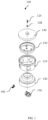
- FIG. 1 is a schematic representation of an exploded view of a pneumatic flow controlling device (100) with various components in aligned position in accordance with an embodiment of the present disclosure.
- the term 'pneumatic flow controlling device' is defined as a pneumatic flow valve system situated in a working space within the pneumatic vacuum elevator for air controlling utilized to move the pneumatic vacuum elevator.
- the device (100) includes a perforated component (110) disposed on a bottom component (120) coupled to a top surface of a pneumatic vacuum elevator.
- the bottom component of the pneumatic flow controlling device (100) may be coupled to an integrated unit of elevator cylinder placed at the top surface of the pneumatic vacuum elevator.
- the device (100) also includes a diaphragm component (130) to expand and compress based on the air circulation.
- the diaphragm component (130) is disposed over the perforated component (110).
- the diaphragm component (130) expands when the air flows through the multiple perforations from the outside atmosphere.
- the diaphragm component (130) compresses when the air is released from the diaphragm component (130) to a low-pressure area.
- the device (100) also includes a regulation unit comprising an orifice, wherein the orifice enables the air circulation from outside atmosphere into the elevator cylinder for the actuation of the diaphragm component (130).
- the orifice of the regulation unit is opened or covered for regulating the air circulation using an Allen screw (125) and a Hex flange locknut (128).
- the air circulation through the orifice into the external cylinder in predefined volume determines a rate of descending movement of the elevator cabin (not shown in FIG. 1 ).
- the device (100) also includes a top component (140) mechanically coupled to the diaphragm component (130).
- the top component (140) covers the pneumatic flow controlling device.
- the perforated component (110), the bottom component (120), and the top component (140) are assembled using an adhesive material.
- the device (100) also includes a primary valve (150) to allow an air supply to the elevator cylinder for controlling movement of an elevator cabin within a tubular pathway based on a control signal received from an elevator controller.
- the primary valve (150) may include an electric solenoid valve.
- the primary valve (150) is coupled to the diaphragm component (130) and opens or closes to allow the air supply based on the control signal received from the elevator controller. Upon receiving the control signal, the primary valve (150) switches on to an open position and enables vacuum inside the elevator cylinder to pass through the primary valve (150).
- the device (100) also includes a secondary valve (160) to allow the air supply to the elevator cylinder for dynamically varying speed of the elevator cabin at one or more landing positions.
- the secondary valve (160) may include a solenoid valve attached to an outer surface of the bottom component (120) of the pneumatic flow controlling device (100).
- the secondary valve (160) opens for a predefined interval of time simultaneously from closing of the primary valve, wherein the primary valve (150) closes based on the control signal received from the elevator controller.
- the predefined interval of time may include a time interval of 3 seconds simultaneously from the closing of the primary valve (150).
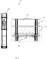
- FIG. 2 illustrates a schematic representation of an embodiment of a pneumatic vacuum elevator (170) with an assembly of a pneumatic flow controlling device in accordance with an embodiment of a present disclosure.
- the pneumatic vacuum elevator (170) includes an elevator cabin (178) to accommodate one or more passengers.
- the elevator cabin (178) is inserted within an external cylinder assembly (175) and ascends or descends in a vertical direction within a tubular pathway.
- the pneumatic vacuum elevator (170) also includes a motor unit (180) which includes a pneumatic flow controlling device (100).
- the motor control unit (180) is located at the top surface of the pneumatic vacuum elevator (100).
- the pneumatic flow controlling device (100) is coupled to an integrated unit of elevator cylinder placed at the top surface of the pneumatic vacuum elevator.
- the pneumatic flow controlling device (100) may be located at a convenient working space utilized in conjunction with the pneumatic vacuum elevator (170).
- the pneumatic flow controlling device (100) includes a perforated component which includes multiple perforations to enable air circulation from outside to inside of the elevator cylinder.
- the device (100) also includes a diaphragm component (not shown in FIG. 2 ) to expand and compress based on the air circulation.
- the diaphragm component is disposed over the perforated component.
- the diaphragm component expands when the air flows through the multiple perforations from the outside atmosphere.
- the diaphragm compresses when the air is released from the diaphragm component to a low-pressure area.
- the device (100) also includes a regulation unit comprising an orifice, wherein the orifice enables the air circulation from outside atmosphere into the elevator cylinder for actuation of the diaphragm component.
- the orifice of the regulation unit is opened or covered for regulating the air circulation using an Allen screw and a Hex flange lock nut.
- the device (100) also includes a primary valve to allow air supply to the elevator cylinder for controlling movement of an elevator cabin within a tubular pathway based on a control signal received from an elevator controller.
- the primary valve may include an electric solenoid valve.
- the primary valve is coupled to the diaphragm component and opens or closes to allow the air supply based on the control signal received from the elevator controller. Upon receiving the control signal, the primary valve switches on to an open position and enables vacuum inside the elevator cylinder to pass through the primary valve.
- the device (100) also includes a secondary valve to allow the air supply to the elevator cylinder for dynamically varying speed of the elevator cabin at one or more landing positions.
- the secondary valve may include a solenoid valve attached to an outer surface of the bottom component of the pneumatic flow controlling device. The secondary valve opens simultaneously when the primary valve (150) closes. Similarly, the secondary valve (160) closes after the predefined time interval, which is set, wherein the primary valve closes based on the control signal received from the elevator controller.
- the predefined interval of time may include a time interval of 3 seconds from closing of the primary valve.
- the device (100) also includes a top component mechanically coupled to the diaphragm component.
- the top component covers the pneumatic flow controlling device.
- the perforated component, the bottom component, and the top component are assembled using an adhesive material.
- FIG. 3 illustrates a schematic representation of another embodiment (179) of a pneumatic vacuum elevator (170) with an assembly of a pneumatic flow controlling device in accordance with an embodiment of a present disclosure.
- the pneumatic vacuum elevator (170) includes an elevator cabin (178) to accommodate one or more passengers.
- the elevator cabin (178) ascends or descends in a vertical direction within a tubular pathway for transiting the one or more passengers.
- the pneumatic vacuum elevator (170) also includes an external split unit assembly (181) located at a convenient working space in conjunction with the pneumatic vacuum elevator (170).
- the external split unit assembly is coupled to a top surface of the pneumatic vacuum elevator (170) via a pipe (182).
- the pipe (182) may include a poly vinyl chloride (PVC) pipe.
- the split unit assembly includes a motor unit (180) and a pneumatic flow controlling device (100).
- the pneumatic flow controlling device (100) includes a perforated component disposed on a bottom component (120) coupled to a top surface of a pneumatic vacuum elevator (170).
- the perforated component includes multiple perforations to enable air circulation (183) from outside to inside of the elevator cylinder.
- the device (100) also includes a diaphragm component to expand and compress based on the air circulation (183).
- the device (100) also includes a primary valve to allow air supply to the elevator cylinder for controlling movement of an elevator cabin within a tubular pathway based on a control signal received from an elevator controller.
- the device (100) also includes a secondary valve to allow the air supply to the elevator cylinder for dynamically varying speed of the elevator cabin at one or more landing positions.
- FIG. 4 illustrates a schematic representation of an embodiment of a pneumatic flow controlling device (100) with functional orientation and air flow direction in accordance with an embodiment of the present disclosure.
- the pneumatic flow controlling device (100) used in the pneumatic vacuum elevator allows airflow from a motor unit to inside of an elevator cylinder, in such a way that it releases vacuum pressure from the inside of the elevator cylinder allowing an elevator cabin to descend.
- the pneumatic flow controlling device (100) includes a perforated component (110) disposed on a bottom component (120) coupled to a top surface of a pneumatic vacuum elevator.
- the device (100) also includes a diaphragm component (130) to expand and compress based on the air circulation.
- the diaphragm component (130) is disposed over the perforated component (110).
- the diaphragm component (130) compresses when the air flows through the multiple perforations from the outside atmosphere. Similarly, the diaphragm component (130) expands when the air is released from the diaphragm component (130) to a low-pressure area.
- the device (100) also includes a top component (140) mechanically coupled to the diaphragm component (130).
- the top component (140) covers the pneumatic flow controlling device (100).
- the top component (140), the perforated component (110) and the bottom component (120) are assembled together using an adhesive material.
- a steel plate is placed inbuilt with the top component (140) the pneumatic flow controlling device (100).
- the device (100) also includes a primary valve (150) which is coupled with the diaphragm component (130).
- the device (100) also includes a secondary valve (160) which is attached in the outer surface of the bottom component (120) of the pneumatic flow controlling device (100).
- FIG. 4 (a) illustrates a schematic representation of an embodiment of a pneumatic flow controlling device (100) with functional orientation and air flow direction at a normal condition in accordance with an embodiment of the present disclosure.
- the secondary valve (160) is closed, the primary valve (150) is also closed normally, and the diaphragm component (130) works in normal airflow conditions.
- the airflow is not allowed to enter via the bottom component (120) of the flow controlling device (100) from the outside atmosphere.
- the airflow is not allowed to the flow controlling device (100), the elevator cabin does not move in downward direction.
- the top component (140) which is placed on top of the flow controlling device (100) is assembled using an Allen screw (125) and Hex flange lock nut (128) which further regulates the speed of the elevator cabin.
- FIG. 4 (b) illustrates a schematic representation of an embodiment of a pneumatic flow controlling device (100) with functional orientation and airflow direction at compression condition in accordance with an embodiment of the present disclosure.
- the secondary valve (160) is in closed condition.
- the elevator cabin receives an instruction to move downwards from the elevator controller (not shown in FIG. 3 ).
- the elevator controller sends a control signal to the primary valve (150), and the primary valve (150) switches to an open position.
- the atmospheric air passes through the perforated component (110) and enters into the elevator cylinder from the bottom component (120).
- vacuum or low pressure from inside of the elevator cylinder passes through the primary valve (150) and the perforated component to an upper part of the diaphragm component (130) and making it compress towards the upper portion of the diaphragm component (130) formed by the top component (140) and diaphragm component (130). More specifically, the air flows out of the diaphragm component (130) to the low-pressure region.
- the top component (140) which is placed on top of the pneumatic flow controlling device (100) is assembled using the Allen screw (125) and the Hex flange lock nut (128) which is regulating the speed of the elevator cabin.
- FIG. 4 (c) illustrates a schematic representation of an embodiment of a pneumatic flow controlling device (100) with functional orientation and airflow direction at normal condition with an open secondary valve in accordance with an embodiment of the present disclosure.
- the secondary valve (160) is immediately opened for 3 seconds from the time the primary valve (150) is closed.
- the primary valve (150) is closed based on a timer which is located on a panel circuit board of the elevator controller of the pneumatic vacuum elevator.
- the main function of the secondary valve (160) is to dynamically vary the speed of the elevator cabin at one or more landing positions.
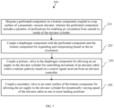
- FIG. 5 is a flow chart representing the steps involved in a method (200) for providing a pneumatic flow controlling device to a pneumatic vacuum elevator in accordance with the embodiment of the present disclosure.
- the method (200) includes disposing of a perforated component on a bottom component coupled to a top surface of a pneumatic vacuum elevator, wherein the perforated component includes multiple perforations for enabling air circulation from outside to inside of the elevator cylinder in step 210.
- the disposing of the perforated component on the bottom component may include disposing of the perforated component on the bottom component coupled with the external cylinder assembly.
- the method (200) also includes coupling a diaphragm component with the perforated component and the bottom component for expanding and compressing based on the air circulation in step 220.
- coupling the diaphragm component with the perforated component and the bottom component may include coupling the diaphragm component, with the perforated component and the bottom component using an adhesive material.
- coupling the diaphragm component may include coupling the diaphragm component with the perforated component and the bottom component for actuation of the diaphragm component based on the air circulation.
- the method (200) also includes coupling a primary valve to the diaphragm component for allowing an air supply to the elevator cylinder for controlling movement of an elevator cabin within a tubular pathway based on a control signal received from an elevator controller in step 230.
- coupling the primary valve to the diaphragm component may include coupling an electric solenoid valve to the diaphragm component.
- the method (200) also includes coupling a secondary valve to an outer surface of the bottom component for allowing the air supply to the elevator cylinder for dynamically varying speed of the elevator cabin at one or more landing positions in step 240.
- Various embodiments of the present disclosure provide an airflow controlling device which consumes low power for operation and facilitates the movement of the pneumatic vacuum elevator within the tubular pathway.
- the present disclosed device reduces vibration or jerk movement due to sudden stop or halt of the elevator cabin of the pneumatic vacuum elevator while landing at the one or more positions.
- the present disclosed device benefits the passenger in the elevator cabin by providing smooth riding experience in the one or more landing positions.
- the present disclosed device enables dynamically regulating the speed of the elevator cabin of the pneumatic vacuum elevator at the one or more landing positions by ensuring safety measurement and also enables smooth descending of the elevator cabin.
Landscapes
- Physics & Mathematics (AREA)
- Engineering & Computer Science (AREA)
- Fluid Mechanics (AREA)
- Automation & Control Theory (AREA)
- Structural Engineering (AREA)
- General Physics & Mathematics (AREA)
- Civil Engineering (AREA)
- Mechanical Engineering (AREA)
- Types And Forms Of Lifts (AREA)
- Fluid-Pressure Circuits (AREA)
- Jet Pumps And Other Pumps (AREA)
- Paper (AREA)
Claims (10)
- Pneumatische Durchflusssteuerungsvorrichtung (100) für einen pneumatischen Vakuumaufzug, wobei die genannte Vorrichtung (100) Folgendes umfasstein perforiertes Bauteil (110), das an einem unteren Bauteil (120) angeordnet ist und dazu bestimmt ist, mit einer oberen Fläche eines Aufzugzylinders des pneumatischen Vakuumaufzugs gekoppelt zu werden, wobeidas perforierte Bauteil (110) eine Vielzahl von Perforationen aufweist, um eine Luftzirkulation von der Außen- zur Innenseite des Aufzugzylinders zu ermöglichen;ein Membranbauteil (130), das mechanisch mit dem perforierten Bauteil (110) und dem unteren Bauteil (120) gekoppelt ist, wobei das Membranbauteil (130) darauf ausgelegt ist, sich basierend auf der Luftzirkulation auszudehnen und zu komprimieren;ein Primärventil (150), das mechanisch mit dem Membranbauteil (130) gekoppelt ist, wobei das Primärventil (150) darauf ausgelegt ist, eine Luftzufuhr zu dem Aufzugzylinder zur Steuerung der Bewegung einer Aufzugskabine (178) im Inneren eines röhrenförmigen Weges basierend auf einem Steuersignal zu ermöglichen, das von einer Aufzugsteuerung empfangen werden soll;wobei die genannte Vorrichtung (100) dadurch gekennzeichnet ist, dass sie ein Sekundärventil (160) umfasst, das mechanisch mit einer äußeren Oberfläche des unteren Bauteils (120) gekoppelt ist, wobei das Sekundärventil (160) darauf ausgelegt ist, die Luftzufuhr zu dem Aufzugzylinder für eine dynamische Veränderung der Geschwindigkeit der Aufzugskabine (178) an einer oder mehreren Landepositionen zu ermöglichen.
- Vorrichtung (100) nach Anspruch 1, wobei das untere Bauteil (120) dazu bestimmt ist, mit einer integrierten Einheit des Aufzugzylinders gekoppelt zu werden, die an der oberen Fläche des pneumatischen Vakuumaufzugs angeordnet ist.
- Vorrichtung (100) nach Anspruch 1, wobei das untere Bauteil (120) der pneumatischen Durchflusssteuerungsvorrichtung (100) dazu bestimmt ist, an einer externen Split-Einheit-Baugruppe (181) des pneumatischen Vakuumaufzugs (170) angeordnet zu werden, wobei die externe Split-Einheit-Baugruppe (181) über eine Leitung mit der oberen Fläche des pneumatischen Vakuumaufzugs (170) gekoppelt ist.
- Vorrichtung (100) nach Anspruch 1, umfassend ein oberes Bauteil (140), das mechanisch mit dem Membranbauteil (130) gekoppelt ist, wobei das obere Bauteil (140) darauf ausgelegt ist, die pneumatische Durchflusssteuerungsvorrichtung (100) abzudecken.
- Vorrichtung (100) nach Anspruch 1, umfassend eine Regeleinheit mit einer Öffnung, wobei die Öffnung die Luftzirkulation von der Außenatmosphäre in den Aufzugzylinder zur Betätigung des Membranbauteils (130) ermöglicht.
- Vorrichtung (100) nach Anspruch 5, wobei die Öffnung der Regeleinheit zur Regelung der Luftzirkulation mit einer Innensechskantschraube (125) und einer Sechskant-Sicherungsmutter mit Flansch (128) geöffnet oder abgedeckt wird.
- Vorrichtung (100) nach Anspruch 6, wobei die Luftzirkulation durch die Öffnung in den externen Zylinder in einem zuvor festgelegten Volumen eine Geschwindigkeit der Abwärtsbewegung der Aufzugskabine (178) bestimmt.
- Vorrichtung (100) nach Anspruch 1,
wobei das Sekundärventil (160) sich innerhalb eines zuvor festgelegten Zeitintervalls beim Schließen des Primärventils (150) öffnet, wobei das Primärventil (150) basierend auf dem von der Aufzugsteuerung empfangenen Steuersignal schließt. - Pneumatischer Vakuumaufzug (170) mit einer pneumatischen Durchflusssteuerungsvorrichtung (100), der das Folgendes umfasst:eine externe Zylinderbaugruppe (175), die eine Aufzugskabine (178) umfasst, die darauf ausgelegt ist, einen oder mehrere Fahrgäste aufzunehmen;eine Motoreinheit (180), die mechanisch mit der externen Zylinderbaugruppe (175) gekoppelt ist, wobei die Motoreinheit (180) die pneumatische Durchflusssteuerungsvorrichtung (100) nach Anspruch 1 umfasst.
- Verfahren (200) zum Bereitstellen einer pneumatischen Durchflusssteuerungsvorrichtung für einen pneumatischen Vakuumaufzug, umfassend:Anordnen eines perforierten Bauteils auf einem unteren Bauteil, das mit einer oberen Fläche eines Aufzugzylinders des pneumatischen Vakuumaufzugs gekoppelt ist, wobei das perforierte Bauteil eine Vielzahl von Perforationen umfasst, um eine Luftzirkulation von der Außenseite zur Innenseite des Aufzugzylinders (210) zu ermöglichen;Koppeln eines Membranbauteils mit dem perforierten Bauteil und dem unteren Bauteil zum Ausdehnen und Komprimieren basierend auf der Luftzirkulation (220);Koppeln eines Primärventils mit dem Membranbauteil, um eine Luftzufuhr zu dem Aufzugzylinder zu ermöglichen, um die Bewegung einer Aufzugskabine im Inneren eines röhrenförmigen Weges basierend auf einem von einer Aufzugsteuerung (230) empfangenen Steuersignals zu steuern; undKoppeln eines Sekundärventils mit einer äußeren Oberfläche des unteren Bauteils, um die Luftzufuhr zum Aufzugzylinder zu ermöglichen und so die Geschwindigkeit der Aufzugskabine in einer oder mehreren Landepositionen (240) dynamisch zu verändern.
Applications Claiming Priority (2)
| Application Number | Priority Date | Filing Date | Title |
|---|---|---|---|
| IN202041023082 | 2020-06-02 | ||
| PCT/IB2020/058408 WO2021245454A1 (en) | 2020-06-02 | 2020-09-10 | A pneumatic flow controlling device for a pneumatic vacuum elevator and a method thereof |
Publications (4)
| Publication Number | Publication Date |
|---|---|
| EP4157775A1 EP4157775A1 (de) | 2023-04-05 |
| EP4157775A4 EP4157775A4 (de) | 2024-04-17 |
| EP4157775B1 true EP4157775B1 (de) | 2024-12-18 |
| EP4157775C0 EP4157775C0 (de) | 2024-12-18 |
Family
ID=78831618
Family Applications (1)
| Application Number | Title | Priority Date | Filing Date |
|---|---|---|---|
| EP20938620.0A Active EP4157775B1 (de) | 2020-06-02 | 2020-09-10 | Pneumatische durchflusssteuerungsvorrichtung für einen pneumatischen vakuumaufzug und verfahren dafür |
Country Status (6)
| Country | Link |
|---|---|
| US (1) | US12091288B2 (de) |
| EP (1) | EP4157775B1 (de) |
| AU (1) | AU2020451088B2 (de) |
| CA (1) | CA3181104A1 (de) |
| ES (1) | ES3007220T3 (de) |
| WO (1) | WO2021245454A1 (de) |
Families Citing this family (2)
| Publication number | Priority date | Publication date | Assignee | Title |
|---|---|---|---|---|
| IN202041023093A (de) * | 2020-06-02 | 2020-06-12 | ||
| WO2025114767A1 (en) * | 2023-11-27 | 2025-06-05 | Ruphavathy Vishal | An airflow controller in a pneumatic vacuum elevator and a method to operate the same |
Family Cites Families (10)
| Publication number | Priority date | Publication date | Assignee | Title |
|---|---|---|---|---|
| US5583326A (en) * | 1992-01-08 | 1996-12-10 | Sors Carlos Alberto | Pneumatic elevator by depressure |
| UY23516A1 (es) * | 1992-01-08 | 1993-03-30 | Sors Carlos Alberto | Ascensor neumático por depresión |
| US6085873A (en) * | 1999-05-27 | 2000-07-11 | Macchi; Anselmo John | Pneumatic elevator |
| KR101160644B1 (ko) | 2011-06-17 | 2012-06-28 | 전귀동 | 공압을 이용한 엘리베이터 |
| CN203079477U (zh) | 2012-12-28 | 2013-07-24 | 江南嘉捷电梯股份有限公司 | 气动电梯装置 |
| US9248995B2 (en) * | 2013-02-27 | 2016-02-02 | Carlos M. Ascua | Vacuum valve |
| CN104401851B (zh) | 2014-11-25 | 2017-02-01 | 昆山通祐电梯有限公司 | 一种多层真空气动电梯 |
| US9845155B2 (en) * | 2016-01-05 | 2017-12-19 | The Boeing Company | Systems and methods for conveying passengers, flight crew personnel, containers and food service carts |
| KR101922048B1 (ko) * | 2016-12-22 | 2019-02-13 | (주)신우 프론티어 | 진공식 엘리베이터 |
| US12503341B2 (en) * | 2020-07-09 | 2025-12-23 | Blissera Corp. | Cabin mechanics of panoramic vacuum elevator |
-
2020
- 2020-09-10 ES ES20938620T patent/ES3007220T3/es active Active
- 2020-09-10 WO PCT/IB2020/058408 patent/WO2021245454A1/en not_active Ceased
- 2020-09-10 US US17/928,630 patent/US12091288B2/en active Active
- 2020-09-10 AU AU2020451088A patent/AU2020451088B2/en active Active
- 2020-09-10 CA CA3181104A patent/CA3181104A1/en active Pending
- 2020-09-10 EP EP20938620.0A patent/EP4157775B1/de active Active
Also Published As
| Publication number | Publication date |
|---|---|
| ES3007220T3 (en) | 2025-03-19 |
| EP4157775A1 (de) | 2023-04-05 |
| CA3181104A1 (en) | 2021-12-09 |
| US12091288B2 (en) | 2024-09-17 |
| US20230137918A1 (en) | 2023-05-04 |
| WO2021245454A1 (en) | 2021-12-09 |
| EP4157775C0 (de) | 2024-12-18 |
| AU2020451088A1 (en) | 2023-01-19 |
| AU2020451088B2 (en) | 2025-03-27 |
| EP4157775A4 (de) | 2024-04-17 |
Similar Documents
| Publication | Publication Date | Title |
|---|---|---|
| EP4157775B1 (de) | Pneumatische durchflusssteuerungsvorrichtung für einen pneumatischen vakuumaufzug und verfahren dafür | |
| US5447211A (en) | Pneumatic elevator by depressure | |
| US5583326A (en) | Pneumatic elevator by depressure | |
| US9248995B2 (en) | Vacuum valve | |
| EP3441345A2 (de) | Geteiltes vakuum-aufzugssystem | |
| KR101969947B1 (ko) | 고층건물의 제연장치 | |
| CA3181088A1 (en) | Seal assembly for a pneumatic vacuum elevator | |
| WO2021245524A1 (en) | An integrated noise suppression apparatus for a pneumatic vacuum elevator | |
| JP2000219458A (ja) | 油圧エレベ―タ装置 | |
| WO2025114767A1 (en) | An airflow controller in a pneumatic vacuum elevator and a method to operate the same | |
| JP2008110469A (ja) | エアードライバー | |
| CA3181115A1 (en) | Overload valve assembly for a pneumatic vacuum elevator | |
| JP3251863B2 (ja) | エレベータ装置 | |
| JP2011219215A5 (de) | ||
| AU2022313571A1 (en) | A split unit with reduced headroom assembly for a pneumatic vacuum elevator | |
| WO2012161674A1 (en) | Machine roomless hydraulic elevator system | |
| CN110023222B (zh) | 电梯装置 | |
| JPH06312890A (ja) | エレベータ乗りかご | |
| WO2017138060A1 (ja) | エレベータ装置 | |
| JP6933618B2 (ja) | エレベータ装置 | |
| JP7145772B2 (ja) | エレベーター | |
| JP5023564B2 (ja) | エレベータ装置 | |
| JPH1081472A (ja) | エレベータ | |
| KR0146621B1 (ko) | 유압엘리베이터의 제어장치 | |
| WO2025262503A1 (en) | A plate structure for an elevator cabin and a method to assemble the same |
Legal Events
| Date | Code | Title | Description |
|---|---|---|---|
| STAA | Information on the status of an ep patent application or granted ep patent |
Free format text: STATUS: THE INTERNATIONAL PUBLICATION HAS BEEN MADE |
|
| PUAI | Public reference made under article 153(3) epc to a published international application that has entered the european phase |
Free format text: ORIGINAL CODE: 0009012 |
|
| STAA | Information on the status of an ep patent application or granted ep patent |
Free format text: STATUS: REQUEST FOR EXAMINATION WAS MADE |
|
| 17P | Request for examination filed |
Effective date: 20221220 |
|
| AK | Designated contracting states |
Kind code of ref document: A1 Designated state(s): AL AT BE BG CH CY CZ DE DK EE ES FI FR GB GR HR HU IE IS IT LI LT LU LV MC MK MT NL NO PL PT RO RS SE SI SK SM TR |
|
| P01 | Opt-out of the competence of the unified patent court (upc) registered |
Effective date: 20230411 |
|
| DAV | Request for validation of the european patent (deleted) | ||
| DAX | Request for extension of the european patent (deleted) | ||
| A4 | Supplementary search report drawn up and despatched |
Effective date: 20240320 |
|
| RIC1 | Information provided on ipc code assigned before grant |
Ipc: F16K 7/00 20060101ALI20240314BHEP Ipc: B66B 11/04 20060101ALI20240314BHEP Ipc: B66B 9/04 20060101AFI20240314BHEP |
|
| GRAP | Despatch of communication of intention to grant a patent |
Free format text: ORIGINAL CODE: EPIDOSNIGR1 |
|
| STAA | Information on the status of an ep patent application or granted ep patent |
Free format text: STATUS: GRANT OF PATENT IS INTENDED |
|
| INTG | Intention to grant announced |
Effective date: 20240827 |
|
| GRAS | Grant fee paid |
Free format text: ORIGINAL CODE: EPIDOSNIGR3 |
|
| GRAA | (expected) grant |
Free format text: ORIGINAL CODE: 0009210 |
|
| STAA | Information on the status of an ep patent application or granted ep patent |
Free format text: STATUS: THE PATENT HAS BEEN GRANTED |
|
| AK | Designated contracting states |
Kind code of ref document: B1 Designated state(s): AL AT BE BG CH CY CZ DE DK EE ES FI FR GB GR HR HU IE IS IT LI LT LU LV MC MK MT NL NO PL PT RO RS SE SI SK SM TR |
|
| REG | Reference to a national code |
Ref country code: CH Ref legal event code: EP |
|
| REG | Reference to a national code |
Ref country code: DE Ref legal event code: R096 Ref document number: 602020043546 Country of ref document: DE |
|
| REG | Reference to a national code |
Ref country code: IE Ref legal event code: FG4D |
|
| U01 | Request for unitary effect filed |
Effective date: 20250114 |
|
| U07 | Unitary effect registered |
Designated state(s): AT BE BG DE DK EE FI FR IT LT LU LV MT NL PT RO SE SI Effective date: 20250120 |
|
| P04 | Withdrawal of opt-out of the competence of the unified patent court (upc) registered |
Free format text: CASE NUMBER: APP_2621/2025 Effective date: 20250116 |
|
| REG | Reference to a national code |
Ref country code: ES Ref legal event code: FG2A Ref document number: 3007220 Country of ref document: ES Kind code of ref document: T3 Effective date: 20250319 |
|
| PG25 | Lapsed in a contracting state [announced via postgrant information from national office to epo] |
Ref country code: HR Free format text: LAPSE BECAUSE OF FAILURE TO SUBMIT A TRANSLATION OF THE DESCRIPTION OR TO PAY THE FEE WITHIN THE PRESCRIBED TIME-LIMIT Effective date: 20241218 |
|
| PG25 | Lapsed in a contracting state [announced via postgrant information from national office to epo] |
Ref country code: NO Free format text: LAPSE BECAUSE OF FAILURE TO SUBMIT A TRANSLATION OF THE DESCRIPTION OR TO PAY THE FEE WITHIN THE PRESCRIBED TIME-LIMIT Effective date: 20250318 |
|
| PG25 | Lapsed in a contracting state [announced via postgrant information from national office to epo] |
Ref country code: GR Free format text: LAPSE BECAUSE OF FAILURE TO SUBMIT A TRANSLATION OF THE DESCRIPTION OR TO PAY THE FEE WITHIN THE PRESCRIBED TIME-LIMIT Effective date: 20250319 |
|
| PG25 | Lapsed in a contracting state [announced via postgrant information from national office to epo] |
Ref country code: RS Free format text: LAPSE BECAUSE OF FAILURE TO SUBMIT A TRANSLATION OF THE DESCRIPTION OR TO PAY THE FEE WITHIN THE PRESCRIBED TIME-LIMIT Effective date: 20250318 |
|
| PG25 | Lapsed in a contracting state [announced via postgrant information from national office to epo] |
Ref country code: SM Free format text: LAPSE BECAUSE OF FAILURE TO SUBMIT A TRANSLATION OF THE DESCRIPTION OR TO PAY THE FEE WITHIN THE PRESCRIBED TIME-LIMIT Effective date: 20241218 |
|
| PG25 | Lapsed in a contracting state [announced via postgrant information from national office to epo] |
Ref country code: PL Free format text: LAPSE BECAUSE OF FAILURE TO SUBMIT A TRANSLATION OF THE DESCRIPTION OR TO PAY THE FEE WITHIN THE PRESCRIBED TIME-LIMIT Effective date: 20241218 |
|
| PG25 | Lapsed in a contracting state [announced via postgrant information from national office to epo] |
Ref country code: IS Free format text: LAPSE BECAUSE OF FAILURE TO SUBMIT A TRANSLATION OF THE DESCRIPTION OR TO PAY THE FEE WITHIN THE PRESCRIBED TIME-LIMIT Effective date: 20250418 |
|
| PG25 | Lapsed in a contracting state [announced via postgrant information from national office to epo] |
Ref country code: SK Free format text: LAPSE BECAUSE OF FAILURE TO SUBMIT A TRANSLATION OF THE DESCRIPTION OR TO PAY THE FEE WITHIN THE PRESCRIBED TIME-LIMIT Effective date: 20241218 |
|
| PG25 | Lapsed in a contracting state [announced via postgrant information from national office to epo] |
Ref country code: CZ Free format text: LAPSE BECAUSE OF FAILURE TO SUBMIT A TRANSLATION OF THE DESCRIPTION OR TO PAY THE FEE WITHIN THE PRESCRIBED TIME-LIMIT Effective date: 20241218 |
|
| U20 | Renewal fee for the european patent with unitary effect paid |
Year of fee payment: 6 Effective date: 20250910 |
|
| PGFP | Annual fee paid to national office [announced via postgrant information from national office to epo] |
Ref country code: GB Payment date: 20250902 Year of fee payment: 6 |
|
| PLBE | No opposition filed within time limit |
Free format text: ORIGINAL CODE: 0009261 |
|
| STAA | Information on the status of an ep patent application or granted ep patent |
Free format text: STATUS: NO OPPOSITION FILED WITHIN TIME LIMIT |
|
| 26N | No opposition filed |
Effective date: 20250919 |
|
| PGFP | Annual fee paid to national office [announced via postgrant information from national office to epo] |
Ref country code: ES Payment date: 20251002 Year of fee payment: 6 |