EP4157677B1 - Einbau eines lautsprechers und/oder eines automatischen notrufsystems in das armaturenbrett eines kraftfahrzeugs - Google Patents
Einbau eines lautsprechers und/oder eines automatischen notrufsystems in das armaturenbrett eines kraftfahrzeugs Download PDFInfo
- Publication number
- EP4157677B1 EP4157677B1 EP21732396.3A EP21732396A EP4157677B1 EP 4157677 B1 EP4157677 B1 EP 4157677B1 EP 21732396 A EP21732396 A EP 21732396A EP 4157677 B1 EP4157677 B1 EP 4157677B1
- Authority
- EP
- European Patent Office
- Prior art keywords
- loudspeaker
- fixing
- bowl
- support
- dashboard
- Prior art date
- Legal status (The legal status is an assumption and is not a legal conclusion. Google has not performed a legal analysis and makes no representation as to the accuracy of the status listed.)
- Active
Links
Images


Classifications
-
- B—PERFORMING OPERATIONS; TRANSPORTING
- B60—VEHICLES IN GENERAL
- B60K—ARRANGEMENT OR MOUNTING OF PROPULSION UNITS OR OF TRANSMISSIONS IN VEHICLES; ARRANGEMENT OR MOUNTING OF PLURAL DIVERSE PRIME-MOVERS IN VEHICLES; AUXILIARY DRIVES FOR VEHICLES; INSTRUMENTATION OR DASHBOARDS FOR VEHICLES; ARRANGEMENTS IN CONNECTION WITH COOLING, AIR INTAKE, GAS EXHAUST OR FUEL SUPPLY OF PROPULSION UNITS IN VEHICLES
- B60K37/00—Dashboards
- B60K37/10—Arrangements for attaching the dashboard to the vehicle
-
- B—PERFORMING OPERATIONS; TRANSPORTING
- B60—VEHICLES IN GENERAL
- B60R—VEHICLES, VEHICLE FITTINGS, OR VEHICLE PARTS, NOT OTHERWISE PROVIDED FOR
- B60R11/00—Arrangements for holding or mounting articles, not otherwise provided for
- B60R11/02—Arrangements for holding or mounting articles, not otherwise provided for for radio sets, television sets, telephones, or the like; Arrangement of controls thereof
- B60R11/0217—Arrangements for holding or mounting articles, not otherwise provided for for radio sets, television sets, telephones, or the like; Arrangement of controls thereof for loud-speakers
-
- B—PERFORMING OPERATIONS; TRANSPORTING
- B60—VEHICLES IN GENERAL
- B60H—ARRANGEMENTS OF HEATING, COOLING, VENTILATING OR OTHER AIR-TREATING DEVICES SPECIALLY ADAPTED FOR PASSENGER OR GOODS SPACES OF VEHICLES
- B60H1/00—Heating, cooling or ventilating devices
- B60H1/00507—Details, e.g. mounting arrangements, desaeration devices
- B60H1/00514—Details of air conditioning housings
- B60H1/0055—Details of air conditioning housings the housing or parts thereof being integrated in other devices, e.g. dashboard
-
- B—PERFORMING OPERATIONS; TRANSPORTING
- B60—VEHICLES IN GENERAL
- B60H—ARRANGEMENTS OF HEATING, COOLING, VENTILATING OR OTHER AIR-TREATING DEVICES SPECIALLY ADAPTED FOR PASSENGER OR GOODS SPACES OF VEHICLES
- B60H1/00—Heating, cooling or ventilating devices
- B60H1/00507—Details, e.g. mounting arrangements, desaeration devices
- B60H1/00557—Details of ducts or cables
- B60H1/00564—Details of ducts or cables of air ducts
-
- B—PERFORMING OPERATIONS; TRANSPORTING
- B60—VEHICLES IN GENERAL
- B60K—ARRANGEMENT OR MOUNTING OF PROPULSION UNITS OR OF TRANSMISSIONS IN VEHICLES; ARRANGEMENT OR MOUNTING OF PLURAL DIVERSE PRIME-MOVERS IN VEHICLES; AUXILIARY DRIVES FOR VEHICLES; INSTRUMENTATION OR DASHBOARDS FOR VEHICLES; ARRANGEMENTS IN CONNECTION WITH COOLING, AIR INTAKE, GAS EXHAUST OR FUEL SUPPLY OF PROPULSION UNITS IN VEHICLES
- B60K35/00—Instruments specially adapted for vehicles; Arrangement of instruments in or on vehicles
- B60K35/20—Output arrangements, i.e. from vehicle to user, associated with vehicle functions or specially adapted therefor
- B60K35/26—Output arrangements, i.e. from vehicle to user, associated with vehicle functions or specially adapted therefor using acoustic output
-
- B—PERFORMING OPERATIONS; TRANSPORTING
- B60—VEHICLES IN GENERAL
- B60K—ARRANGEMENT OR MOUNTING OF PROPULSION UNITS OR OF TRANSMISSIONS IN VEHICLES; ARRANGEMENT OR MOUNTING OF PLURAL DIVERSE PRIME-MOVERS IN VEHICLES; AUXILIARY DRIVES FOR VEHICLES; INSTRUMENTATION OR DASHBOARDS FOR VEHICLES; ARRANGEMENTS IN CONNECTION WITH COOLING, AIR INTAKE, GAS EXHAUST OR FUEL SUPPLY OF PROPULSION UNITS IN VEHICLES
- B60K37/00—Dashboards
- B60K37/20—Dashboard panels
-
- B—PERFORMING OPERATIONS; TRANSPORTING
- B62—LAND VEHICLES FOR TRAVELLING OTHERWISE THAN ON RAILS
- B62D—MOTOR VEHICLES; TRAILERS
- B62D25/00—Superstructure or monocoque structure sub-units; Parts or details thereof not otherwise provided for
- B62D25/08—Front or rear portions
- B62D25/14—Dashboards as superstructure sub-units
- B62D25/142—Dashboards as superstructure sub-units having ventilation channels incorporated therein
-
- H—ELECTRICITY
- H04—ELECTRIC COMMUNICATION TECHNIQUE
- H04R—LOUDSPEAKERS, MICROPHONES, GRAMOPHONE PICK-UPS OR LIKE ACOUSTIC ELECTROMECHANICAL TRANSDUCERS; ELECTRIC HEARING AIDS; PUBLIC ADDRESS SYSTEMS
- H04R1/00—Details of transducers, loudspeakers or microphones
- H04R1/02—Casings; Cabinets ; Supports therefor; Mountings therein
- H04R1/026—Supports for loudspeaker casings
-
- B—PERFORMING OPERATIONS; TRANSPORTING
- B60—VEHICLES IN GENERAL
- B60K—ARRANGEMENT OR MOUNTING OF PROPULSION UNITS OR OF TRANSMISSIONS IN VEHICLES; ARRANGEMENT OR MOUNTING OF PLURAL DIVERSE PRIME-MOVERS IN VEHICLES; AUXILIARY DRIVES FOR VEHICLES; INSTRUMENTATION OR DASHBOARDS FOR VEHICLES; ARRANGEMENTS IN CONNECTION WITH COOLING, AIR INTAKE, GAS EXHAUST OR FUEL SUPPLY OF PROPULSION UNITS IN VEHICLES
- B60K2360/00—Indexing scheme associated with groups B60K35/00 or B60K37/00 relating to details of instruments or dashboards
- B60K2360/84—Mounting of dashboard components
-
- B—PERFORMING OPERATIONS; TRANSPORTING
- B60—VEHICLES IN GENERAL
- B60R—VEHICLES, VEHICLE FITTINGS, OR VEHICLE PARTS, NOT OTHERWISE PROVIDED FOR
- B60R11/00—Arrangements for holding or mounting articles, not otherwise provided for
- B60R2011/0001—Arrangements for holding or mounting articles, not otherwise provided for characterised by position
- B60R2011/0003—Arrangements for holding or mounting articles, not otherwise provided for characterised by position inside the vehicle
- B60R2011/0005—Dashboard
-
- B—PERFORMING OPERATIONS; TRANSPORTING
- B60—VEHICLES IN GENERAL
- B60R—VEHICLES, VEHICLE FITTINGS, OR VEHICLE PARTS, NOT OTHERWISE PROVIDED FOR
- B60R11/00—Arrangements for holding or mounting articles, not otherwise provided for
- B60R2011/0042—Arrangements for holding or mounting articles, not otherwise provided for characterised by mounting means
- B60R2011/0049—Arrangements for holding or mounting articles, not otherwise provided for characterised by mounting means for non integrated articles
- B60R2011/005—Connection with the vehicle part
- B60R2011/0059—Connection with the vehicle part using clips, clamps, straps or the like
-
- B—PERFORMING OPERATIONS; TRANSPORTING
- B60—VEHICLES IN GENERAL
- B60R—VEHICLES, VEHICLE FITTINGS, OR VEHICLE PARTS, NOT OTHERWISE PROVIDED FOR
- B60R11/00—Arrangements for holding or mounting articles, not otherwise provided for
- B60R2011/0042—Arrangements for holding or mounting articles, not otherwise provided for characterised by mounting means
- B60R2011/0049—Arrangements for holding or mounting articles, not otherwise provided for characterised by mounting means for non integrated articles
- B60R2011/0064—Connection with the article
- B60R2011/0066—Connection with the article using screws, bolts, rivets or the like
-
- H—ELECTRICITY
- H04—ELECTRIC COMMUNICATION TECHNIQUE
- H04R—LOUDSPEAKERS, MICROPHONES, GRAMOPHONE PICK-UPS OR LIKE ACOUSTIC ELECTROMECHANICAL TRANSDUCERS; ELECTRIC HEARING AIDS; PUBLIC ADDRESS SYSTEMS
- H04R2201/00—Details of transducers, loudspeakers or microphones covered by H04R1/00 but not provided for in any of its subgroups
- H04R2201/02—Details casings, cabinets or mounting therein for transducers covered by H04R1/02 but not provided for in any of its subgroups
- H04R2201/021—Transducers or their casings adapted for mounting in or to a wall or ceiling
-
- H—ELECTRICITY
- H04—ELECTRIC COMMUNICATION TECHNIQUE
- H04R—LOUDSPEAKERS, MICROPHONES, GRAMOPHONE PICK-UPS OR LIKE ACOUSTIC ELECTROMECHANICAL TRANSDUCERS; ELECTRIC HEARING AIDS; PUBLIC ADDRESS SYSTEMS
- H04R2499/00—Aspects covered by H04R or H04S not otherwise provided for in their subgroups
- H04R2499/10—General applications
- H04R2499/13—Acoustic transducers and sound field adaptation in vehicles
Definitions
- the invention lies in the field of motor vehicles which can be equipped with a loudspeaker and/or an automatic emergency call system placed at the level of the dashboard.
- the invention is aimed in particular at the mounting system for such a loudspeaker and/or such an automatic emergency call system.
- Automatic emergency calling, or "e-Call" systems allow a crashed car to instantly call emergency services via a mobile phone network and send its precise location, which the vehicle's occupants whether conscious or not.
- Automatic emergency call systems are installed in vehicles intended for the European market, and in some vehicles intended for other markets. They are therefore not installed in all vehicles produced.
- the document DE102016208977 describes the mounting of an “e-Call” type module on the dashboard of a motor vehicle. Mounting is accomplished by a dedicated mounting bracket comprising a holding part (for holding a control unit) and a mounting part connected to the holding part such that the mounting part is curved upwards or downwards down from the holding part.
- the documents US5709601 , US2011/176689 , And EP0713798 describe vehicle dashboards comprising a defrost duct
- the document JP2002186077 describes an arrangement for attaching a loudspeaker
- the document JP2001310653 describes an arrangement for fixing a loudspeaker on a dashboard comprising a defrost duct conforming to the preamble of claim 1.
- the support for a central speaker and/or an automatic emergency call system is carried by a support mounted on the defrost duct associated with the dashboard or made from material with this last.
- the defrost ducts are known to those skilled in the art, for example, the document WO2011/010053 describes a dashboard architecture intended to be placed under the windshield of a motor vehicle.
- the dashboard comprises a panel and a lower cross member spaced from this panel.
- An assembly is arranged between the two which notably comprises a connection opening with an air conditioning device and a defrosting duct which extends under the windshield and which is connected to said opening.
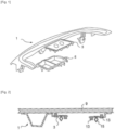
- FIG. 1 shows a defrost duct 1 comprising a support 3 for equipment, for example for a loudspeaker 7 (visible in Figure 3 ) and/or an automatic emergency call system (not shown).
- the support 3 comes integrally with the body of the defrost duct 1.
- the assembly is molded in one piece, for example by injection, in a composite or thermoplastic material.
- the support 3 will therefore carry the loudspeaker 7 but also the loudspeaker bowl 5 in which said loudspeaker 7 is inserted.
- the loudspeaker 7 and the associated loudspeaker bowl 5 are not present on all vehicles, but are installed only on part of the range associated with a given silhouette.
- the panel 9 of the dashboard has or not an opening intended to receive a speaker grille 11.
- the mounting of the speaker 7 and its associated bowl 5 is generally done after an operation of fixing the defrost duct 1 on the panel 9 of the dashboard.
- This fixing operation is, for example, an ultrasonic or vibration welding operation.
- the means of fixing and/or clipping (13, 15) of the loudspeaker bowl and the loudspeaker are mounted by default on the defrost duct 1.
- the figure 2 is a sectional view of an assembly comprising a panel 9 of the dashboard welded to a defrost duct 1 intended for a vehicle without a central speaker. It can be seen that the means for fixing the bowl and the loudspeaker, such as locking nuts 13 and clipping means 15 are present although unused.
- the invention proposes to provide a response to at least one of the drawbacks and/or problems encountered in the prior art.
- the invention aims to propose a solution for adapting a dashboard to the mounting of a central speaker and/or an automatic emergency call system which is simple and economical; and which preferably is more robust than known solutions.
- the subject of the invention is a defrosting duct for a motor vehicle, said defrosting duct comprising a body showing a chute and being intended to be fixed to a dashboard panel, the defrosting duct defrosting is remarkable in that it comprises at least one speaker bowl and in that at least one speaker bowl is integral with said body.
- the speaker bowl(s) have an opening and the defrost duct is made of a thermoplastic material or a composite material with a thermoplastic matrix.
- At least one speaker bowl includes a rim forming the perimeter of the opening of the speaker bowl. Said rim shows a series of ribs for attaching said speaker bowl to a dashboard panel by ultrasonic or vibration welding.
- the invention consists of making the defrost duct carry the loudspeaker bowl instead of the loudspeaker support. Since the means of fixing the loudspeaker and the loudspeaker grille are carried by the loudspeaker support and not by the loudspeaker bowl, these fixings will not be present by default when the dashboard is not equipped with a speaker.
- the speaker support will be added to the defrost duct when attaching the dashboard panel to the defroster duct but only when necessary, i.e. when the dashboard panel edge shows an opening for the speaker or an automatic emergency call system. Also, this configuration is advantageous in that the speaker bowl itself is fixed by welding to the dashboard panel, making the whole thing more robust.
- the invention is remarkable in that it offers a simple and economical response to the problem posed.
- At least one speaker bowl comprises at least one internal separation partition arranged to divide it into at least two compartments. This configuration allows the speaker bowl to receive at least two acoustic devices chosen from at least one loudspeaker and/or an automatic emergency call system.
- At least one speaker bowl comprises at least one fixing interface for fixing a speaker support.
- At least one fixing interface comprises clipping means intended to cooperate with complementary clipping means carried by the loudspeaker support.
- At least one fixing interface is arranged on a peripheral shoulder arranged in the speaker bowl.
- the peripheral shoulder is contained in the loudspeaker bowl, that is to say that the peripheral shoulder is arranged lower than the rim of the loudspeaker bowl intended for its attachment to the panel of the speaker board. edge.
- the subject of the invention is a
- the invention relates to an assembly remarkable in that it comprises a defrost duct according to the first aspect and a loudspeaker support.
- the loudspeaker support is intended to be fixed on the defrost duct and is in the form of a plate showing at least one opening, and comprising at least one fixing interface or means of fixing to a loudspeaker bowl. speaker carried by said defrost duct.
- the plate shows at least two openings and/or the means for fixing to the speaker bowl are clipping means.
- the plate has an upper face and a lower face and the clipping means are in the form of at least one male element projecting from the lower face of the plate.
- the loudspeaker support further comprises clipping means for fixing a loudspeaker grille.
- the clipping means for fixing a loudspeaker grille comprise at least one clipping sleeve intended to receive a clipping foot carried by the loudspeaker grille.
- the loudspeaker support further comprises fixing means intended for fixing a loudspeaker and/or an automatic emergency call system.
- the fixing means for fixing a loudspeaker and/or an automatic emergency call system comprise at least one locking nut.
- the plate showing an upper face and a lower face the loudspeaker support is remarkable in that it comprises a peripheral shoulder rising from the upper face of the plate.
- the speaker support is made of a thermoplastic material or of a composite material with a thermoplastic matrix and the peripheral shoulder shows a series of ribs intended for fixing said speaker support on a board panel. edge by ultrasonic or vibration welding.
- the invention relates to a dashboard with a dashboard panel, remarkable in that the dashboard panel is fixed to a defroster duct according to the first aspect or to an assembly according to the third aspect .
- the invention relates to a motor vehicle remarkable in that it comprises a dashboard with a dashboard panel, remarkable in that the dashboard panel is fixed to a defrost duct according to the first aspect or to a set according to the third aspect.
- the invention relates to a motor vehicle remarkable in that it comprises a dashboard according to the fourth aspect.
- the invention relates to a method of mounting a dashboard according to the fourth aspect, or a dashboard for a motor vehicle according to the fifth aspect, the method comprising a step of fixing a defrost duct on a dashboard panel; the method being remarkable in that the defrost duct is according to the first aspect and in that when the dashboard panel shows an opening facing a speaker bowl carried by said defroster, the method comprises a step of fixing a speaker support to said speaker bowl carried out prior to the step of fixing a defrost duct on a dashboard panel.
- the step of fixing a defrost duct on a dashboard panel is carried out by ultrasonic or vibration welding.
- the step of fixing a loudspeaker support to said loudspeaker bowl is done by clipping.
- the method further comprises a step of fixing an automatic emergency call system and/or a loudspeaker on said loudspeaker support carried out after the The step of fixing a defrost duct to a dashboard panel.
- the method further comprises a step of fixing a loudspeaker grille on said loudspeaker support carried out after the step of fixing an automatic emergency call system and/or of a speaker on said speaker support.
- the invention relates to the use of a defrost duct according to the first aspect and/or of an assembly according to the third aspect for the assembly of an automatic emergency call system and/or a loudspeaker in a motor vehicle; preferably in a motor vehicle according to the fifth aspect.
- the invention relates to the use of a defrost duct according to the first aspect and/or an assembly according to the third aspect for mounting an automatic emergency call system and/or a speaker in a dashboard according to the fourth aspect.
- the term “include” is synonymous with “include” and is not restrictive in that it authorizes the presence of other elements in the defrost duct, the speaker support, the board board or vehicle or other steps in the process to which it relates. It is understood that the term “understand” includes the terms “consist of”. The terms “high” and “low” will be understood in their general sense, the term “low” designating greater proximity to the ground. In the different figures, the same references designate identical or similar elements.
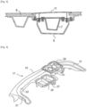
- the defrost duct 17 comprises a body with a general U-shape showing a central part 19 and two side parts 21, said U-shaped body being configured to be open towards the rear of the motor vehicle when the defrost duct 17 is mounted in a motor vehicle.
- the body of the defrosting duct 17 is intended to be fixed to a dashboard panel 9 (visible on the figures 6 And 7 ) and shows a chute 23 extending along the entire length of the body and being intended to be connected to an air conditioning device (not shown).
- the chute 23 is open towards the top and is intended to cooperate with the dashboard panel 9 to form an air distribution channel for defrosting the windshield of the vehicle.
- the defrost duct 17 according to the invention is remarkable in that it comprises at least one loudspeaker bowl 25 and in that at least one loudspeaker bowl 25 is integral with said body.
- the speaker bowl(s) 25 show an opening, open towards the top.
- at least one loudspeaker bowl 25 is arranged at the central part 19 of said body so as to be placed between the two lateral parts 21, that is to say inside said U.
- at least a speaker bowl 25 is integral with the central part 19 of said body.
- the speaker bowl(s) 25 extend from the body of the defrost duct 17.
- At least one loudspeaker bowl 25 comprises at least one internal separation partition 27 arranged to divide it into at least two compartments.
- the speaker bowl 25 can be used for at least two adjacently mounted acoustic devices such as a loudspeaker and an automatic emergency call system (not shown in figures 4 And 5 ).
- the associated loudspeaker support 29 will include at least one opening 31 intended to face one of the compartments; for example, a single opening if only one of the compartments is intended to be used.
- the associated loudspeaker support 29 will comprise at least two openings 31, each intended to face one of the compartments.
- the defrost conduit 17 is preferably made of a thermoplastic material or of a composite material with a thermoplastic matrix.
- a thermoplastic material or the thermoplastic matrix of the composite material from polypropylene (PP), polyethylene (PE), polyphthalamide (PPA), polyetheretherketone (PEEK), polyphenylene sulfide (PPS), polyamide-imide (PAI), polyetherimide (PEI), polyarylamide (PAA), or polyamide (PA) such as for example polyamide 6 (PA 6 or polycaprolactam ) or polyamide 6.6 (PA 6.6 or polyhexamethylene adipamide), or their mixtures.
- the thermoplastic material or the thermoplastic matrix of the composite material is polypropylene or polyamide.
- the defrost duct 17 is assembled with the dashboard panel 9 by ultrasonic or vibration welding.
- Ultrasonic or vibration welding is a technique known to those skilled in the art which will therefore not be described in detail in this specification.
- the parts to be assembled each show a series of ribs at their respective fixing interfaces. High-frequency vibrations are sent to the parts to be assembled via a vibrating tool. Under the effect of the heat generated by the vibrations, the ribs will melt and the materials of the different parts will merge at the fixing interfaces. The welding is thus carried out.
- the loudspeaker bowl(s) 25 being open towards the top, therefore facing the dashboard panel 9, at least one loudspeaker bowl 25 comprises a rim 33 forming the periphery of the the opening of the speaker bowl 25.
- This rim 33 forms an interface for fixing the speaker bowl 25 with the dashboard panel 9.
- the peripheral rim 33 of the speaker bowl shows a series of ribs 35 intended for fixing said speaker bowl 25 to a dashboard panel 9 by ultrasonic or vibration welding.
- At least one speaker bowl 25 comprises at least one fixing interface for fixing a speaker support 29.
- at least one fixing interface comprises clipping means 37 intended to cooperate with complementary clipping means 39 carried by the loudspeaker support 29.
- at least one fixing interface includes an opening 37 for the passage of a clip fixing forming a clipping means 39 carried by the loudspeaker support 29.
- At least one fixing interface for fixing a loudspeaker support 29 is arranged on a peripheral shoulder 41 arranged in the loudspeaker bowl 25.
- the peripheral shoulder is contained in the loudspeaker bowl, that is to say that the peripheral shoulder is arranged lower than the rim of the loudspeaker bowl intended for its attachment to the panel of the speaker board. edge.
- the loudspeaker support 29 is advantageously contained at least in part and preferably in its entirety in the loudspeaker bowl 25. Fastening by clipping is advantageous in that it does not require tools and can therefore be easily carried out when assembling the different parts for welding. Those skilled in the art can nevertheless carry out this fixing by other means.
- the loudspeaker support 29 intended to be fixed on a defrost duct 17 is preferably in the form of a plate showing at least one opening 31 and comprises at least one fixing interface or fixing means and/or clipping 39 to a loudspeaker bowl 25 carried by said defrost conduit 17.
- the plate shows at least two openings 31.
- the means of fixing and/or clipping 39 to the loudspeaker bowl are clipping means 39.
- the plate showing an upper face and a lower face, the clipping means 39 are advantageously in the form of at least one male element projecting from the lower face of the plate.
- the means for fixing the acoustic device(s) and the loudspeaker grille 11 are carried by the loudspeaker support 29. They will therefore not be present by default on all vehicle models but will only be present when they are necessary.
- the loudspeaker support 29 comprises clipping means 15 for fixing a loudspeaker grille 11 by clipping.
- said clipping means 15 comprise at least one clipping sleeve intended to receive a clipping foot 43 carried through the speaker grille 11.
- the clipping socket is oriented to be open upwards, clipping being done by pressing the clipping foot(s) 43 of the speaker grille 11 into the clipping socket(s) of the speaker support.
- the loudspeaker support 29 advantageously comprises fixing means 13 intended for fixing a loudspeaker and/or an automatic emergency call system.
- the fixing means 13 for fixing a loudspeaker and/or an automatic emergency call system comprise at least one locking nut.
- the locking nut(s) are arranged to be opened upwards so as to be accessible through the opening shown by the dashboard panel 9.
- the clipping fixing of the speaker support 29 is a temporary so-called “holding” fixing.
- Final fixation is done by ultrasonic or vibration welding. This configuration is advantageous in terms of the robustness of the assembly and to avoid the generation of parasitic noises coming from vibrations when the vehicle is rolling.
- the loudspeaker support 29 comprises a peripheral shoulder 45 rising from the upper face of the plate.
- This peripheral shoulder 45 forms an interface for fixing the speaker support 29 with the dashboard panel 9.
- the peripheral shoulder 45 of the loudspeaker support 29 shows a series of ribs 47 intended for fixing said loudspeaker support 29 on a panel 9 of a board. edge by ultrasonic or vibration welding.
- the invention is remarkable in that the ultrasonic or vibration welding will weld together at least three parts, namely the dashboard panel 9, the defrost duct 17 including its speaker bowl(s) 25 and the speaker support(s) 29.
- the dashboard thus formed is more robust than those of the prior art in which the speaker bowl was assembled by screwing and not by welding. The elimination of the associated screwing operations further adds to the savings generated by the invention.
- the speaker support 29 is made of a thermoplastic material or of a composite material with a thermoplastic matrix.
- the loudspeaker support 29 is made of the same material as the defrost duct 17.
- the peripheral shoulder 45 shows a series of ribs 47 intended for fixing said loudspeaker support 29 on a dashboard panel 9 by ultrasonic or vibration welding.
- the invention also relates to a method of mounting a dashboard for a vehicle according to the invention, the assembly method involving a defrost duct 17 according to the invention, that is to say comprising a body with a chute 23 and at least one speaker bowl 25 made integrally with said body.
- the method comprises the following steps, given in chronological order: the supply of a dashboard panel 9 and a defrost duct 17 according to the invention. Determining the presence or not of an opening on the dashboard panel 9 intended to be positioned opposite a speaker bowl 25 carried by said defrost duct 17. When the dashboard panel 9 does not show an opening, a step of fixing the defrost duct 17 on the dashboard panel 9 is directly implemented.
- the method comprises an additional step of fixing a loudspeaker support 29 on the loudspeaker bowl(s) 25 intended to be positioned facing the or openings prior to the step of fixing the defrost duct 17 on the dashboard panel 9.
- the fixed loudspeaker support 29 is preferably dimensioned to be contained in the loudspeaker bowl 25.
- the step of fixing a loudspeaker support 29 to a loudspeaker bowl 25 is done by clipping.
- a loudspeaker support 29 is fixed to a loudspeaker bowl 25
- those skilled in the art will benefit from the step of fixing the defrost duct 17 on the dashboard panel 9 either carried out by ultrasonic or vibration welding.
- the assembly process continues with the implementation of a step of fixing a system automatic emergency call and/or a loudspeaker 7 on said loudspeaker support.
- This fixing is advantageously done by screwing.
- the method implements a step of fixing a speaker grille 11 on said speaker support. Fixing the speaker grille 11 is advantageously done by clipping.
Landscapes
- Engineering & Computer Science (AREA)
- Mechanical Engineering (AREA)
- Chemical & Material Sciences (AREA)
- Combustion & Propulsion (AREA)
- Transportation (AREA)
- Physics & Mathematics (AREA)
- Thermal Sciences (AREA)
- Acoustics & Sound (AREA)
- Signal Processing (AREA)
- Fittings On The Vehicle Exterior For Carrying Loads, And Devices For Holding Or Mounting Articles (AREA)
- Details Of Audible-Bandwidth Transducers (AREA)
Claims (8)
- Entfrostungskanal (17) für ein Kraftfahrzeug, wobei der Entfrostungskanal (17) einen Körper aufweist, der eine Rinne (23) aufweist und dazu bestimmt ist, an einer Armaturenbrettplatte (9) befestigt zu werden, wobei der Entfrostungskanal (17) mindestens eine Lautsprecherschale (25) aufweist, die eine Öffnung aufweist, wobei mindestens eine Lautsprecherschale (25) mit dem Körper einstückig ausgebildet ist, wobei der Entfrostungskanal (17) dadurch gekennzeichnet ist, dass er aus einem thermoplastischen Material oder einem Verbundmaterial mit einer Thermoplastische Matrix und dadurch gekennzeichnet, dass mindestens eine Lautsprecherschale (25) einen Flansch (33) aufweist, der den Umfang der Öffnung der Lautsprecherschale (25) bildet, wobei der Flansch (33) eine Reihe von Rippen (35) aufweist, die zum Befestigen der Lautsprecherschale (25) an einer Armaturenbrettplatte (9) durch Ultraschall- oder Vibrationsschweißen bestimmt sind, wobei vorzugsweise mindestens eine Lautsprecherschale (25) mindestens eine innere Trennwand (27) aufweist, die zum Teilen der Schale angeordnet ist mindestens zwei Fächer.
- Entfrostungskanal (17) nach einem der Ansprüche 1, dadurch gekennzeichnet, dass mindestens eine Lautsprecherschale (25) mindestens eine Befestigungsschnittstelle zur Befestigung eines Lautsprecherträgers (29) aufweist; vorzugsweise mindestens eine Befestigungsschnittstelle Klemmmittel (37) zum Zusammenwirken mit komplementären Klemmmitteln (39) aufweist, die von dem Lautsprecherträger (29) getragen werden, und/oder mindestens eine Befestigungsschnittstelle an einer umlaufenden Schulter (41) angeordnet ist, die in der oberen Schale (25) angeordnet ist Lautsprecher.
- Baugruppe, die eine Abtauleitung (17) nach einem der Ansprüche 1 bis 2 und einen Lautsprecherträger (29) zur Befestigung an der Abtauleitung (17) umfasst, wobei der Träger (29) in Form einer Platte vorliegt, die mindestens eine Öffnung (31) aufweist und mindestens eine Befestigungsfläche oder Mittel zur Befestigung an einer Lautsprecherschale (25) umfasst, die von der Abtauleitung (17) getragen wird; vorzugsweise zeigt die Platte mindestens zwei Öffnungen (31) und/oder Mittel zur Befestigung an der Schale (17) 25) Lautsprecher sind Cliping-Mittel.
- Anordnung nach dem vorhergehenden Anspruch, die ferner Clipmittel (15) zur Befestigung eines Lautsprechergitters (11) aufweist und/oder die ferner Befestigungsmittel (13) zur Befestigung eines Lautsprechers und/oder eines automatischen Notrufsystems aufweist; wobei vorzugsweise die Befestigungsmittel (13) zur Befestigung eines Lautsprechers und/oder eines automatischen Notrufsystems mindestens eine Sperrmutter (13) aufweisen.
- Anordnung nach einem der Ansprüche 3 oder 4, bei der die Platte eine Ober- und eine Unterseite aufweist, wobei der Träger (29) eine umlaufende Schulter (45) aufweist, die von der Oberseite der Platte absteht; wobei vorzugsweise der Lautsprecherhalter (29) aus einem thermoplastischen Material oder einem Verbundmaterial mit einer thermoplastischen Matrix hergestellt ist und die umlaufende Schulter (45) eine Reihe von Rippen (47) aufweist, um den Lautsprecherhalter (29) an einer Armaturenbrettplatte (9) durch Ultraschall- oder Vibrationsschweißen zu befestigen
- Kraftfahrzeug, dadurch gekennzeichnet, dass es ein Armaturenbrett mit einer Armaturenbrettplatte (9) umfasst, dadurch gekennzeichnet, dass die Armaturenbrettplatte (9) an einem Abtaukanal (17) nach einem der Ansprüche 1 bis 2 oder an einer Anordnung nach einem der Ansprüche 3 bis 5 befestigt ist.
- Verfahren zum Montieren eines Armaturenbretts für ein Kraftfahrzeug nach Anspruch 6, wobei das Verfahren einen Schritt des Anbringens einer Entfrostungsleitung (17) an einer Armaturenbrettplatte (9) umfasst; wobei das Verfahren dadurch gekennzeichnet ist, dass die Entfrostungsleitung (17) nach einem der Ansprüche 1 bis 2 ist, und dass, wenn die Armaturenbrettplatte (9) eine Öffnung gegenüber einer Lautsprecherschale (25) zeigt, die von der Entfrostungsleitung (17) getragen wird, das Verfahren einen Schritt des Anbringens einer Lautsprecherhalterung (29) umfasst Sie werden auf die Lautsprecherschale (25) aufgebracht, die vor dem Schritt der Befestigung einer Entfrostungsleitung (17) an einer Armaturenbrettplatte (9) hergestellt wird, wobei der Schritt der Befestigung der Entfrostungsleitung (17) an der Armaturenbrettplatte (9) durch Ultraschallschweißen oder Vibration erfolgt.
- Verfahren nach Anspruch 7, dadurch gekennzeichnet, dass es ferner einen Schritt des Anbringens eines automatischen Notrufsystems und/oder eines Lautsprechers (7) an dem Lautsprecherträger (29) umfasst, der nach dem Schritt des Anbringens einer Abtauleitung (17) an einer Armaturenbrettplatte (9) ausgeführt wird; vorzugsweise umfasst es ferner einen Schritt des Anbringens eines Lautsprechergitters (11) an dem Lautsprecherträger (29), der nach dem Schritt des Anbringens eines automatischen und/oder automatischen Notrufsystems ausgeführt wird oder einem Lautsprecher (7) an der Lautsprecherhalterung (29).
Applications Claiming Priority (2)
| Application Number | Priority Date | Filing Date | Title |
|---|---|---|---|
| FR2005523A FR3110514B1 (fr) | 2020-05-25 | 2020-05-25 | Implantation d’un haut-parleur et/ou d’un système d’appel d’urgence automatique dans la planche de bord d’un véhicule automobile |
| PCT/FR2021/050730 WO2021240083A1 (fr) | 2020-05-25 | 2021-04-27 | Implantation d'un haut-parleur et/ou d'un système d'appel d'urgence automatique dans la planche de bord d'un véhicule automobile |
Publications (2)
| Publication Number | Publication Date |
|---|---|
| EP4157677A1 EP4157677A1 (de) | 2023-04-05 |
| EP4157677B1 true EP4157677B1 (de) | 2024-07-17 |
Family
ID=73038058
Family Applications (1)
| Application Number | Title | Priority Date | Filing Date |
|---|---|---|---|
| EP21732396.3A Active EP4157677B1 (de) | 2020-05-25 | 2021-04-27 | Einbau eines lautsprechers und/oder eines automatischen notrufsystems in das armaturenbrett eines kraftfahrzeugs |
Country Status (4)
| Country | Link |
|---|---|
| EP (1) | EP4157677B1 (de) |
| CN (1) | CN115697772A (de) |
| FR (1) | FR3110514B1 (de) |
| WO (1) | WO2021240083A1 (de) |
Family Cites Families (19)
| Publication number | Priority date | Publication date | Assignee | Title |
|---|---|---|---|---|
| NL6804718A (de) | 1968-04-04 | 1969-10-07 | ||
| US4032725A (en) * | 1976-09-07 | 1977-06-28 | Motorola, Inc. | Speaker mounting |
| JPS57143909U (de) * | 1981-03-05 | 1982-09-09 | ||
| JPH01240341A (ja) * | 1988-03-23 | 1989-09-25 | Mazda Motor Corp | 車両用スピーカ取付構造 |
| GB9423776D0 (en) * | 1994-11-25 | 1995-01-11 | Acg Deutschland Gmbh | Dashboard assembly |
| EP0713798B1 (de) * | 1994-11-25 | 1998-04-29 | Delphi Automotive Systems Deutschland GmbH | Armaturenbrett-Anordnung |
| JP2952850B2 (ja) * | 1996-09-18 | 1999-09-27 | ダイムラー−ベンツ・アクチエンゲゼルシヤフト | 計器盤 |
| JPH11180187A (ja) * | 1997-12-22 | 1999-07-06 | Inoac Corporation:Kk | 車両用インストルメントパネル |
| JP3693885B2 (ja) * | 2000-04-28 | 2005-09-14 | 日産車体株式会社 | インストルメントパネル |
| JP3997266B2 (ja) * | 2000-12-15 | 2007-10-24 | 株式会社ケンウッド | スピーカ装置、スピーカ装置の取付構造及びスピーカ装置の取付構造 |
| WO2009050820A1 (ja) * | 2007-10-19 | 2009-04-23 | Pioneer Corporation | スピーカ用取付部材及びスピーカユニットの固定構造 |
| FR2948325B1 (fr) | 2009-07-21 | 2013-03-29 | Faurecia Interieur Ind | Structure de planche de bord de vehicule automobile et vehicule automobile comportant une telle structure. |
| US8488818B2 (en) * | 2010-01-15 | 2013-07-16 | Nissan North America, Inc. | Interior structural assembly for a vehicle |
| DE102010005028B4 (de) * | 2010-01-20 | 2023-08-10 | Dr. Ing. H.C. F. Porsche Aktiengesellschaft | Aufnahmeeinrichtung für Lautsprecher in einem Kraftfahrzeug |
| DE102010005326B4 (de) * | 2010-01-22 | 2018-07-05 | Dr. Ing. H.C. F. Porsche Aktiengesellschaft | Einstückiges Abdeckelement |
| JP6324215B2 (ja) * | 2014-05-29 | 2018-05-16 | カルソニックカンセイ株式会社 | グリル装置 |
| JP6485223B2 (ja) | 2015-05-28 | 2019-03-20 | スズキ株式会社 | コントローラ取付構造 |
| JP6638592B2 (ja) * | 2016-07-26 | 2020-01-29 | 三菱自動車エンジニアリング株式会社 | 車両のアンテナ取付構造 |
| CN206264799U (zh) * | 2016-12-02 | 2017-06-20 | 上海汽车集团股份有限公司 | 汽车仪表板结构及汽车 |
-
2020
- 2020-05-25 FR FR2005523A patent/FR3110514B1/fr active Active
-
2021
- 2021-04-27 CN CN202180038221.6A patent/CN115697772A/zh active Pending
- 2021-04-27 EP EP21732396.3A patent/EP4157677B1/de active Active
- 2021-04-27 WO PCT/FR2021/050730 patent/WO2021240083A1/fr not_active Ceased
Also Published As
| Publication number | Publication date |
|---|---|
| WO2021240083A1 (fr) | 2021-12-02 |
| FR3110514B1 (fr) | 2023-10-06 |
| CN115697772A (zh) | 2023-02-03 |
| FR3110514A1 (fr) | 2021-11-26 |
| EP4157677A1 (de) | 2023-04-05 |
Similar Documents
| Publication | Publication Date | Title |
|---|---|---|
| FR2955529A1 (fr) | Element de recouvrement pour tableau de bord d'un vehicule automobile | |
| FR2860278A1 (fr) | Bride de fixation pour tuyau de transport de fluide | |
| EP2471690B1 (de) | Befestigungssystem einer Fernbedienung eines elektronischen Gehäuses in einem Kraftfahrzeug | |
| FR3063468A1 (fr) | Platine d’attache et de guidage pour tuyaux et/ou faisceaux cheminant a l’interieur d’un montant de baie. | |
| WO2021019157A1 (fr) | Déflecteur aérodynamique destiné à être fixé contre le soubassement de caisse d'un véhicule | |
| EP4157677B1 (de) | Einbau eines lautsprechers und/oder eines automatischen notrufsystems in das armaturenbrett eines kraftfahrzeugs | |
| FR2768099A1 (fr) | Siege de vehicule dote de haut-parleurs | |
| WO2003052341A1 (fr) | Assemblage perfectionne pour maintenir un equipement de vehicule automobile et preserver cet equipement en cas de choc | |
| FR3058923A1 (fr) | Coiffe de pedale automobile surmoulee autour d'un ergot et son procede de fabrication | |
| WO2015090989A1 (fr) | Ensemble comportant une traverse de planche de bord pour véhicule automobile et deux supports latéraux permettant de fixer cette traverse à la caisse du véhicule | |
| EP3853111B1 (de) | Fahrzeug mit einer stossfängerschürze mit laschen zur befestigung an einem spoiler, wobei die laschen einen verbreiterten fuss aufweisen | |
| EP3870498B1 (de) | Kraftfahrzeug mit zweistufigem unterbodendeflektor | |
| WO2020025870A1 (fr) | Vehicule avec deflecteur arriere sous-plancher montrant un chanfrein | |
| EP4508873A1 (de) | Lautsprechergitter mit direktionaler klangfunktion | |
| FR3078030A1 (fr) | Dispositif de guidage a coulissement d’un appui-tete sur le dossier integrant des moyens assurant le transit de signaux electriques. | |
| FR3050600A1 (fr) | Dispositif de diffusion de sons a radiateurs passifs et event bass-reflex. | |
| EP3576423A1 (de) | Lautsprecher, der provisorische haltemittel vor der endgültigen befestigung auf einem aufnahmeteil umfasst | |
| FR3120579A1 (fr) | Support d’un chargeur de batterie électrique d’un véhicule automobile | |
| FR3072923B1 (fr) | Traverse de securite pour un vehicule | |
| WO2019207222A1 (fr) | Embase de montage a pivotement pour accoudoir de dossier de banquette dotee d'un element metallique d'ancrage anti-basculement. | |
| EP0957285B1 (de) | Hydroelastisches Lager, insbesondere für die Aufhängung einer Antriebseinheit an einer Kraftfahrzeugkarosserie | |
| EP3623213B1 (de) | Fahrzeugsitz, der mit einer entfernbaren ablage ausgestattet ist, und einen solchen sitz enthaltendes fahrzeug | |
| EP4299372A1 (de) | Sitzelement und kraftfahrzeugsitz | |
| FR3148329A1 (fr) | Dispositif de câblage pour un véhicule automobile | |
| FR3162412A1 (fr) | Ensemble de freinage de vehicule automobile |
Legal Events
| Date | Code | Title | Description |
|---|---|---|---|
| STAA | Information on the status of an ep patent application or granted ep patent |
Free format text: STATUS: UNKNOWN |
|
| STAA | Information on the status of an ep patent application or granted ep patent |
Free format text: STATUS: THE INTERNATIONAL PUBLICATION HAS BEEN MADE |
|
| PUAI | Public reference made under article 153(3) epc to a published international application that has entered the european phase |
Free format text: ORIGINAL CODE: 0009012 |
|
| STAA | Information on the status of an ep patent application or granted ep patent |
Free format text: STATUS: REQUEST FOR EXAMINATION WAS MADE |
|
| 17P | Request for examination filed |
Effective date: 20221121 |
|
| AK | Designated contracting states |
Kind code of ref document: A1 Designated state(s): AL AT BE BG CH CY CZ DE DK EE ES FI FR GB GR HR HU IE IS IT LI LT LU LV MC MK MT NL NO PL PT RO RS SE SI SK SM TR |
|
| DAV | Request for validation of the european patent (deleted) | ||
| DAX | Request for extension of the european patent (deleted) | ||
| STAA | Information on the status of an ep patent application or granted ep patent |
Free format text: STATUS: EXAMINATION IS IN PROGRESS |
|
| 17Q | First examination report despatched |
Effective date: 20230913 |
|
| RAP3 | Party data changed (applicant data changed or rights of an application transferred) |
Owner name: STELLANTIS AUTO SAS |
|
| GRAP | Despatch of communication of intention to grant a patent |
Free format text: ORIGINAL CODE: EPIDOSNIGR1 |
|
| STAA | Information on the status of an ep patent application or granted ep patent |
Free format text: STATUS: GRANT OF PATENT IS INTENDED |
|
| INTG | Intention to grant announced |
Effective date: 20240306 |
|
| GRAS | Grant fee paid |
Free format text: ORIGINAL CODE: EPIDOSNIGR3 |
|
| GRAA | (expected) grant |
Free format text: ORIGINAL CODE: 0009210 |
|
| STAA | Information on the status of an ep patent application or granted ep patent |
Free format text: STATUS: THE PATENT HAS BEEN GRANTED |
|
| AK | Designated contracting states |
Kind code of ref document: B1 Designated state(s): AL AT BE BG CH CY CZ DE DK EE ES FI FR GB GR HR HU IE IS IT LI LT LU LV MC MK MT NL NO PL PT RO RS SE SI SK SM TR |
|
| REG | Reference to a national code |
Ref country code: CH Ref legal event code: EP |
|
| REG | Reference to a national code |
Ref country code: DE Ref legal event code: R096 Ref document number: 602021015860 Country of ref document: DE |
|
| REG | Reference to a national code |
Ref country code: IE Ref legal event code: FG4D Free format text: LANGUAGE OF EP DOCUMENT: FRENCH |
|
| REG | Reference to a national code |
Ref country code: DE Ref legal event code: R084 Ref document number: 602021015860 Country of ref document: DE |
|
| REG | Reference to a national code |
Ref country code: GB Ref legal event code: 746 Effective date: 20241003 |
|
| REG | Reference to a national code |
Ref country code: LT Ref legal event code: MG9D |
|
| REG | Reference to a national code |
Ref country code: NL Ref legal event code: MP Effective date: 20240717 |
|
| PG25 | Lapsed in a contracting state [announced via postgrant information from national office to epo] |
Ref country code: PT Free format text: LAPSE BECAUSE OF FAILURE TO SUBMIT A TRANSLATION OF THE DESCRIPTION OR TO PAY THE FEE WITHIN THE PRESCRIBED TIME-LIMIT Effective date: 20241118 |
|
| REG | Reference to a national code |
Ref country code: AT Ref legal event code: MK05 Ref document number: 1703821 Country of ref document: AT Kind code of ref document: T Effective date: 20240717 |
|
| PG25 | Lapsed in a contracting state [announced via postgrant information from national office to epo] |
Ref country code: NL Free format text: LAPSE BECAUSE OF FAILURE TO SUBMIT A TRANSLATION OF THE DESCRIPTION OR TO PAY THE FEE WITHIN THE PRESCRIBED TIME-LIMIT Effective date: 20240717 |
|
| PG25 | Lapsed in a contracting state [announced via postgrant information from national office to epo] |
Ref country code: PT Free format text: LAPSE BECAUSE OF FAILURE TO SUBMIT A TRANSLATION OF THE DESCRIPTION OR TO PAY THE FEE WITHIN THE PRESCRIBED TIME-LIMIT Effective date: 20241118 Ref country code: NL Free format text: LAPSE BECAUSE OF FAILURE TO SUBMIT A TRANSLATION OF THE DESCRIPTION OR TO PAY THE FEE WITHIN THE PRESCRIBED TIME-LIMIT Effective date: 20240717 |
|
| PG25 | Lapsed in a contracting state [announced via postgrant information from national office to epo] |
Ref country code: NO Free format text: LAPSE BECAUSE OF FAILURE TO SUBMIT A TRANSLATION OF THE DESCRIPTION OR TO PAY THE FEE WITHIN THE PRESCRIBED TIME-LIMIT Effective date: 20241017 |
|
| PG25 | Lapsed in a contracting state [announced via postgrant information from national office to epo] |
Ref country code: GR Free format text: LAPSE BECAUSE OF FAILURE TO SUBMIT A TRANSLATION OF THE DESCRIPTION OR TO PAY THE FEE WITHIN THE PRESCRIBED TIME-LIMIT Effective date: 20241018 Ref country code: FI Free format text: LAPSE BECAUSE OF FAILURE TO SUBMIT A TRANSLATION OF THE DESCRIPTION OR TO PAY THE FEE WITHIN THE PRESCRIBED TIME-LIMIT Effective date: 20240717 Ref country code: PL Free format text: LAPSE BECAUSE OF FAILURE TO SUBMIT A TRANSLATION OF THE DESCRIPTION OR TO PAY THE FEE WITHIN THE PRESCRIBED TIME-LIMIT Effective date: 20240717 |
|
| PG25 | Lapsed in a contracting state [announced via postgrant information from national office to epo] |
Ref country code: BG Free format text: LAPSE BECAUSE OF FAILURE TO SUBMIT A TRANSLATION OF THE DESCRIPTION OR TO PAY THE FEE WITHIN THE PRESCRIBED TIME-LIMIT Effective date: 20240717 |
|
| PG25 | Lapsed in a contracting state [announced via postgrant information from national office to epo] |
Ref country code: LV Free format text: LAPSE BECAUSE OF FAILURE TO SUBMIT A TRANSLATION OF THE DESCRIPTION OR TO PAY THE FEE WITHIN THE PRESCRIBED TIME-LIMIT Effective date: 20240717 |
|
| PG25 | Lapsed in a contracting state [announced via postgrant information from national office to epo] |
Ref country code: AT Free format text: LAPSE BECAUSE OF FAILURE TO SUBMIT A TRANSLATION OF THE DESCRIPTION OR TO PAY THE FEE WITHIN THE PRESCRIBED TIME-LIMIT Effective date: 20240717 Ref country code: IS Free format text: LAPSE BECAUSE OF FAILURE TO SUBMIT A TRANSLATION OF THE DESCRIPTION OR TO PAY THE FEE WITHIN THE PRESCRIBED TIME-LIMIT Effective date: 20241117 |
|
| PG25 | Lapsed in a contracting state [announced via postgrant information from national office to epo] |
Ref country code: HR Free format text: LAPSE BECAUSE OF FAILURE TO SUBMIT A TRANSLATION OF THE DESCRIPTION OR TO PAY THE FEE WITHIN THE PRESCRIBED TIME-LIMIT Effective date: 20240717 |
|
| PG25 | Lapsed in a contracting state [announced via postgrant information from national office to epo] |
Ref country code: ES Free format text: LAPSE BECAUSE OF FAILURE TO SUBMIT A TRANSLATION OF THE DESCRIPTION OR TO PAY THE FEE WITHIN THE PRESCRIBED TIME-LIMIT Effective date: 20240717 Ref country code: RS Free format text: LAPSE BECAUSE OF FAILURE TO SUBMIT A TRANSLATION OF THE DESCRIPTION OR TO PAY THE FEE WITHIN THE PRESCRIBED TIME-LIMIT Effective date: 20241017 |
|
| PG25 | Lapsed in a contracting state [announced via postgrant information from national office to epo] |
Ref country code: RS Free format text: LAPSE BECAUSE OF FAILURE TO SUBMIT A TRANSLATION OF THE DESCRIPTION OR TO PAY THE FEE WITHIN THE PRESCRIBED TIME-LIMIT Effective date: 20241017 Ref country code: PL Free format text: LAPSE BECAUSE OF FAILURE TO SUBMIT A TRANSLATION OF THE DESCRIPTION OR TO PAY THE FEE WITHIN THE PRESCRIBED TIME-LIMIT Effective date: 20240717 Ref country code: NO Free format text: LAPSE BECAUSE OF FAILURE TO SUBMIT A TRANSLATION OF THE DESCRIPTION OR TO PAY THE FEE WITHIN THE PRESCRIBED TIME-LIMIT Effective date: 20241017 Ref country code: LV Free format text: LAPSE BECAUSE OF FAILURE TO SUBMIT A TRANSLATION OF THE DESCRIPTION OR TO PAY THE FEE WITHIN THE PRESCRIBED TIME-LIMIT Effective date: 20240717 Ref country code: IS Free format text: LAPSE BECAUSE OF FAILURE TO SUBMIT A TRANSLATION OF THE DESCRIPTION OR TO PAY THE FEE WITHIN THE PRESCRIBED TIME-LIMIT Effective date: 20241117 Ref country code: HR Free format text: LAPSE BECAUSE OF FAILURE TO SUBMIT A TRANSLATION OF THE DESCRIPTION OR TO PAY THE FEE WITHIN THE PRESCRIBED TIME-LIMIT Effective date: 20240717 Ref country code: GR Free format text: LAPSE BECAUSE OF FAILURE TO SUBMIT A TRANSLATION OF THE DESCRIPTION OR TO PAY THE FEE WITHIN THE PRESCRIBED TIME-LIMIT Effective date: 20241018 Ref country code: FI Free format text: LAPSE BECAUSE OF FAILURE TO SUBMIT A TRANSLATION OF THE DESCRIPTION OR TO PAY THE FEE WITHIN THE PRESCRIBED TIME-LIMIT Effective date: 20240717 Ref country code: ES Free format text: LAPSE BECAUSE OF FAILURE TO SUBMIT A TRANSLATION OF THE DESCRIPTION OR TO PAY THE FEE WITHIN THE PRESCRIBED TIME-LIMIT Effective date: 20240717 Ref country code: BG Free format text: LAPSE BECAUSE OF FAILURE TO SUBMIT A TRANSLATION OF THE DESCRIPTION OR TO PAY THE FEE WITHIN THE PRESCRIBED TIME-LIMIT Effective date: 20240717 Ref country code: AT Free format text: LAPSE BECAUSE OF FAILURE TO SUBMIT A TRANSLATION OF THE DESCRIPTION OR TO PAY THE FEE WITHIN THE PRESCRIBED TIME-LIMIT Effective date: 20240717 |
|
| PG25 | Lapsed in a contracting state [announced via postgrant information from national office to epo] |
Ref country code: DK Free format text: LAPSE BECAUSE OF FAILURE TO SUBMIT A TRANSLATION OF THE DESCRIPTION OR TO PAY THE FEE WITHIN THE PRESCRIBED TIME-LIMIT Effective date: 20240717 Ref country code: RO Free format text: LAPSE BECAUSE OF FAILURE TO SUBMIT A TRANSLATION OF THE DESCRIPTION OR TO PAY THE FEE WITHIN THE PRESCRIBED TIME-LIMIT Effective date: 20240717 Ref country code: SM Free format text: LAPSE BECAUSE OF FAILURE TO SUBMIT A TRANSLATION OF THE DESCRIPTION OR TO PAY THE FEE WITHIN THE PRESCRIBED TIME-LIMIT Effective date: 20240717 |
|
| REG | Reference to a national code |
Ref country code: DE Ref legal event code: R097 Ref document number: 602021015860 Country of ref document: DE |
|
| PG25 | Lapsed in a contracting state [announced via postgrant information from national office to epo] |
Ref country code: EE Free format text: LAPSE BECAUSE OF FAILURE TO SUBMIT A TRANSLATION OF THE DESCRIPTION OR TO PAY THE FEE WITHIN THE PRESCRIBED TIME-LIMIT Effective date: 20240717 |
|
| PG25 | Lapsed in a contracting state [announced via postgrant information from national office to epo] |
Ref country code: CZ Free format text: LAPSE BECAUSE OF FAILURE TO SUBMIT A TRANSLATION OF THE DESCRIPTION OR TO PAY THE FEE WITHIN THE PRESCRIBED TIME-LIMIT Effective date: 20240717 |
|
| PG25 | Lapsed in a contracting state [announced via postgrant information from national office to epo] |
Ref country code: SK Free format text: LAPSE BECAUSE OF FAILURE TO SUBMIT A TRANSLATION OF THE DESCRIPTION OR TO PAY THE FEE WITHIN THE PRESCRIBED TIME-LIMIT Effective date: 20240717 |
|
| PLBE | No opposition filed within time limit |
Free format text: ORIGINAL CODE: 0009261 |
|
| STAA | Information on the status of an ep patent application or granted ep patent |
Free format text: STATUS: NO OPPOSITION FILED WITHIN TIME LIMIT |
|
| 26N | No opposition filed |
Effective date: 20250422 |
|
| PGFP | Annual fee paid to national office [announced via postgrant information from national office to epo] |
Ref country code: DE Payment date: 20250319 Year of fee payment: 5 |
|
| PG25 | Lapsed in a contracting state [announced via postgrant information from national office to epo] |
Ref country code: SE Free format text: LAPSE BECAUSE OF FAILURE TO SUBMIT A TRANSLATION OF THE DESCRIPTION OR TO PAY THE FEE WITHIN THE PRESCRIBED TIME-LIMIT Effective date: 20240717 |
|
| REG | Reference to a national code |
Ref country code: CH Ref legal event code: H13 Free format text: ST27 STATUS EVENT CODE: U-0-0-H10-H13 (AS PROVIDED BY THE NATIONAL OFFICE) Effective date: 20251125 |
|
| PG25 | Lapsed in a contracting state [announced via postgrant information from national office to epo] |
Ref country code: LU Free format text: LAPSE BECAUSE OF NON-PAYMENT OF DUE FEES Effective date: 20250427 |
|
| PG25 | Lapsed in a contracting state [announced via postgrant information from national office to epo] |
Ref country code: MC Free format text: LAPSE BECAUSE OF FAILURE TO SUBMIT A TRANSLATION OF THE DESCRIPTION OR TO PAY THE FEE WITHIN THE PRESCRIBED TIME-LIMIT Effective date: 20240717 |
|
| REG | Reference to a national code |
Ref country code: BE Ref legal event code: MM Effective date: 20250430 |
|
| PG25 | Lapsed in a contracting state [announced via postgrant information from national office to epo] |
Ref country code: BE Free format text: LAPSE BECAUSE OF NON-PAYMENT OF DUE FEES Effective date: 20250430 |
|
| PG25 | Lapsed in a contracting state [announced via postgrant information from national office to epo] |
Ref country code: CH Free format text: LAPSE BECAUSE OF NON-PAYMENT OF DUE FEES Effective date: 20250430 |
|
| PG25 | Lapsed in a contracting state [announced via postgrant information from national office to epo] |
Ref country code: IT Free format text: LAPSE BECAUSE OF FAILURE TO SUBMIT A TRANSLATION OF THE DESCRIPTION OR TO PAY THE FEE WITHIN THE PRESCRIBED TIME-LIMIT Effective date: 20240717 |
|
| PGFP | Annual fee paid to national office [announced via postgrant information from national office to epo] |
Ref country code: GB Payment date: 20260319 Year of fee payment: 6 |
|
| PG25 | Lapsed in a contracting state [announced via postgrant information from national office to epo] |
Ref country code: IE Free format text: LAPSE BECAUSE OF NON-PAYMENT OF DUE FEES Effective date: 20250427 |
|
| PGFP | Annual fee paid to national office [announced via postgrant information from national office to epo] |
Ref country code: FR Payment date: 20260320 Year of fee payment: 6 |