EP4157674B1 - Rückspiegelanordnung für ein fahrzeug - Google Patents
Rückspiegelanordnung für ein fahrzeug Download PDFInfo
- Publication number
- EP4157674B1 EP4157674B1 EP21716711.3A EP21716711A EP4157674B1 EP 4157674 B1 EP4157674 B1 EP 4157674B1 EP 21716711 A EP21716711 A EP 21716711A EP 4157674 B1 EP4157674 B1 EP 4157674B1
- Authority
- EP
- European Patent Office
- Prior art keywords
- housing
- mirror
- mirror element
- support means
- rear view
- Prior art date
- Legal status (The legal status is an assumption and is not a legal conclusion. Google has not performed a legal analysis and makes no representation as to the accuracy of the status listed.)
- Active
Links
Images

Classifications
-
- B—PERFORMING OPERATIONS; TRANSPORTING
- B60—VEHICLES IN GENERAL
- B60R—VEHICLES, VEHICLE FITTINGS, OR VEHICLE PARTS, NOT OTHERWISE PROVIDED FOR
- B60R1/00—Optical viewing arrangements; Real-time viewing arrangements for drivers or passengers using optical image capturing systems, e.g. cameras or video systems specially adapted for use in or on vehicles
- B60R1/02—Rear-view mirror arrangements
- B60R1/06—Rear-view mirror arrangements mounted on vehicle exterior
Definitions
- the invention relates to a rear-view mirror arrangement for a vehicle, in particular for a tilting vehicle, with a mirror element and a housing accommodating the mirror element.
- rearview mirror assemblies are available that have a bowl-shaped mirror housing with integrated dome-shaped extensions inside the housing, with a mirror glass glued directly onto the dome-shaped extensions using hot glue.
- These rearview mirror assemblies are particularly light due to their simplified design.
- the bonding usually has a certain - albeit very low - elasticity, which means that at least the smallest relative movements of the mirror glass with respect to the housing are possible. Vibrations during vehicle operation therefore lead to unintentional vibrations of the mirror glass. Resonances can occur, particularly when vibrations occur in the range of the natural frequency of the mirror glass, and can have a particularly severe impact on the use of the rearview mirror.
- the EN 10 2009 047 919 A1 relates to a glass unit for mirrors with a glass carrier plate which comprises a front side, a back side and a peripheral edge zone, and a mirror pane which has a mirror pane front side, a mirror pane back side and a peripheral edge, wherein the mirror pane is fastened with its rear side to the front side of the glass carrier plate by means of an adhesive layer, wherein holding webs extend from the front side of the glass carrier plate out of the edge zone of the glass carrier plate, wherein the holding webs are arranged distributed over the peripheral edge zone and wherein the peripheral edge of the mirror pane rests against the holding webs.
- the JP-H01 249544 relates to a mirror with an approximately bowl-shaped mirror housing, whereby the mirror glass is flexibly connected to the mirror housing via a carrier plate.
- the JP-H01 249544 The rearview mirror arrangement disclosed corresponds to the preamble of claim 1.
- the DE 39 23 932 A1 relates to a kit for a vehicle exterior mirror, which has a carrier plate that can be attached to the vehicle for holding the housing, the mirror plate and the adjustment device, wherein connection elements are arranged and designed on the aforementioned components of the kit in such a way that the carrier plate can be used for holding a variety of different mirror and/or housing shapes.
- all land, water and air vehicles that have a corresponding rear-view mirror arrangement can be considered as vehicles within the scope of this description.
- the rear-view mirror arrangement can also be used for watercraft such as boats.
- water vehicles it can be used for both motor-driven vehicles and non-driven vehicles such as bicycles.
- other motor-driven vehicles such as wheelchairs, snowmobiles, tricycles or quads and preferably for so-called tilting vehicles.
- a tilting vehicle includes motorcycles or motorcycle-like motor vehicles such as motor scooters, in particular tiltable two-, three- or four-wheeled motor scooters or the like.
- the mirror element comprises in particular a mirror glass with a mirror surface for providing a mirror effect and is connected directly to the one or more fastening extensions on its rear side.
- These are provided on the inner surface of the housing and can be designed and manufactured in one piece or in one piece with the inner surface or with the housing.
- the fastening extensions and the housing can be manufactured separately from one another and then connected to one another.
- the back of the mirror element is to be understood in particular as the surface of the mirror element that is not intended for use as a mirror surface and faces the interior of the housing.
- the interior of the housing is defined in particular by an interior space or cavity that is completely or at least partially enclosed by the housing.
- the housing can be designed in a shell-like manner, so that the interior of the housing is defined by the interior space delimited by a housing wall.
- the support means are provided, which on the one hand is connected to the mirror element and on the other hand is arranged only in sections or completely around an edge of the mirror element in order to be supported on the housing.
- the support means can be dimensioned and designed in such a way that the support means is positively connected to the housing when installed.
- the positive connection is preferably formed between the support means and the inner surface of the housing. In this way, a precise and play-free connection is achieved, which makes it possible to avoid or at least reduce even small relative movements between the support means and the housing.
- the mirror element connected to the support means benefits from this accordingly.
- the mirror element and the housing are already locally connected to one another via the fastening extensions.
- a (residual) elasticity of this connection cannot be avoided, relative movements, particularly in the form of vibrations, can still occur.
- these relative movements can be effectively counteracted with the help of the additional support means, in that the mirror element is additionally supported on the housing or on its inner surface with the help of the support means. The mirror element therefore remains usable even if vibrations occur during operation of the vehicle.
- This design offers the possibility of dispensing with a separate, massive glass support plate that is difficult to screw in, as is the case with state-of-the-art technology, thus eliminating its additional mass and weight.
- the support means can be connected to the back of the mirror element.
- This connection can preferably be made by means of a material bond, in particular by gluing.
- a force-fitting and/or form-fitting connection of the support means to the back of the mirror element is possible.
- the support itself can be made of plastic or metallic material, for example.
- the support means can be plate-shaped at least in sections and have an edge section which projects at least in sections beyond an edge of the mirror element in order to support the support means on the inner surface of the housing.
- the support means can essentially be designed as a flat, planar component.
- a thickness of the plate-shaped section of the support means can be small compared to a flat extension.
- the thickness can be, for example, less than 5 mm, preferably less than 2 mm, particularly preferably less than 1 mm.
- the projection of the support means beyond the edge of the mirror element can be dimensioned such that the mirror element does not come into contact with the housing in this edge region and instead a gap remains between the mirror element and the housing.
- This gap can be provided only in sections or completely around an edge of the mirror element.
- the projection of the support means relative to the edge of the mirror element can be less than 5 mm, preferably less than 2 mm, particularly preferably less than 1 mm.
- the protrusion of the support means allows the support means to be accommodated and stored in the housing in a precise and form-fitting manner, whereas the mirror element itself has no contact with the housing in its edge area. In this way, larger tolerances that can occur during the manufacture of the mirror element can also be easily compensated. A direct and permanent connection of an edge of the mirror element to the housing would, however, be difficult to provide due to large manufacturing tolerances in the manufacture of mirror glass.
- the support means therefore acts as an intermediate adapter plate and fixes the mirror element in the desired position by means of its own precisely fitting connection with the housing and thus effectively prevents its relative movements with respect to the housing.
- the edge section of the support means can have a conical shape.
- the edge section can form a flange or extension, which is aligned perpendicular to a plane defined by the mirror element and is tapered in this direction. This enables an exact and precise contact with the inner surface of the housing.
- connection between the support means and the back of the mirror element can be designed to be flat, at least in sections.
- the support means can be connected in one or more sections or completely to a surface that is facing surface is in surface connection with the back of the mirror element.
- the connection is designed as a material-locking connection, for example by gluing, preferably by surface gluing, for example by double-sided adhesive tape or double-sided adhesive film.
- the support means can have at least one recess which is arranged such that the support means is recessed at least in a connecting section which is formed by the connection of the rear side of the mirror element with the at least one fastening extension.
- the mirror element can be connected indirectly to the fastening extensions via the support means.
- the support means is applied to the back of the mirror element, which in turn is connected to the at least one fastening extension.
- the support means it is possible for the support means to cover the back of the mirror element completely and flatly.
- the support means can be designed to be non-self-supporting. This means, for example, that the support means itself is not designed to be dimensionally stable, or at least not as a whole, so that the support means does not give the mirror element any additional load-bearing capacity or rigidity. Instead, the mirror element is used as a load-bearing element.
- the support means can have a stiffening rib structure.
- the rib structure is provided, for example, in the edge region of the support means in order to provide a dimensionally stable geometry of at least the edge region of the support element in order to ensure reliable support on the housing.
- connection of the rear side of the mirror element to the at least one fastening extension can be formed in a material-locking and/or form-locking and/or force-locking manner.
- the connection can be made in a simple manner using hot glue or liquid glue.
- the at least one fastening extension can have a connecting surface for surface connection to the rear side of the mirror element at a free end arranged away from the inner surface.
- the at least one fastening extension can be dome-shaped, rib-shaped or designed as a so-called sliding platform (i.e. as a geometry created by a slider from the side wall of the housing) or as a retainer.
- a rear-view mirror arrangement can be provided which has improved vibration properties due to the (edge) support of the mirror element by means of the support means.
- the described structure ensures that the rear-view mirror arrangement is light in weight, thus preventing a negative influence on the driving behavior of the entire vehicle.
- the structure also enables simple assembly, among other things by eliminating the need for screws and at the same time requiring little material.
- a further advantage is the stress-free assembly of the mirror element, which is possible due to the described structure of the rear-view mirror arrangement without the formation of stress.
- a vehicle with at least one rear-view mirror arrangement is proposed, wherein the at least one rear-view mirror arrangement is designed according to this description.
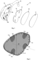
- Fig.1 shows a rearview mirror arrangement 10 for a vehicle (not shown) according to the description in an exploded view.
- the rearview mirror arrangement 10 comprises a mirror element 11 and a housing 12 which accommodates the mirror element 11 and which can be attached to the vehicle via a rod-shaped holder 18.
- the mirror element 11 is formed by a mirror glass which provides a mirror surface.
- the housing 12 is essentially shell-shaped and has an inner surface 12a on which four fastening extensions 12b are formed, wherein the fastening extensions 12b are provided to be connected to a rear side 11a of the mirror element 11 facing the inner surface 12a (cf. Fig.3 ).
- the fastening extensions 12b are dome-shaped and have a connecting surface at a free end arranged away from the inner surface 12a for the surface connection to the rear side 11a of the mirror element 11.
- This connection can be formed in a material-locking and/or form-locking and/or force-locking manner, preferably by means of hot glue or liquid glue.
- the mirror element 11 is connected to a support means 13 (see Fig.2 and 3 ), which is designed to be supported at least in sections on the housing 12.
- the support means 13 is plate-shaped and has an edge section 14 which - as in Fig.3 visible - protrudes beyond an edge 11b of the mirror element 11 in order to support the support means 13 on the inner surface 12a of the housing 12. Due to the protrusion of the support means 13 beyond the edge 11b of the mirror element 11, the mirror element 11 does not come into contact with the housing 12 in this edge region and instead a gap 15 remains between the mirror element 11 and the housing 12. This gap 15 is provided circumferentially along the edge 11b of the mirror element 11.
- the projection of the support means 13 relative to the edge 11b of the mirror element 11 can be less than 5 mm, preferably less than 2 mm.
- the support means 13 is precisely and positively received and stored in the housing 12 thanks to the overhang.
- the mirror element 11 itself has no (direct) contact with the housing 12 in its edge area.
- edge section 14 of the support means 13 has a conical shape.
- the edge section 14 forms a flange 14a or extension which is aligned perpendicular to a plane defined by the mirror element 11 and is tapered in this direction (i.e. in the direction of the housing interior 12c).
- the support element 13 can thus be easily brought into the desired position and brought into precise contact with the inner surface 12a of the housing 12.
- the support means 13 is connected flatly to a large section of the rear side 11a of the mirror element 11.
- the connection can be provided in a material-locking manner, for example by a flat bonding using double-sided adhesive film 16.
- the support means 13 has a plurality of recesses 13a (four recesses 13a are shown as an example), which are arranged in such a way that the support means 13 is recessed at least in a respective connecting section, which is formed by the connection of the rear side 11a of the mirror element 11 to the respective fastening extension 12b.
- the rear side 11a of the mirror element 11 can thus be directly connected to the fastening extensions 12b in these free sections, despite the otherwise flat connection to the support means 13.
- the support means 13 has a stiffening rib structure 17.
- the rib structure 17 is provided in the edge region 14 of the support means 13 in order to ensure a dimensionally stable geometry of at least the edge region 14 of the support element 13 for reliable support on the housing 12.
Landscapes
- Engineering & Computer Science (AREA)
- Multimedia (AREA)
- Mechanical Engineering (AREA)
- Rear-View Mirror Devices That Are Mounted On The Exterior Of The Vehicle (AREA)
Description
- Die Erfindung betrifft eine Rückspiegelanordnung für ein Fahrzeug, insbesondere für ein Neigefahrzeug, mit einem Spiegelelement und einem das Spiegelelement aufnehmenden Gehäuse.
- Bei Fahrzeugen, wie beispielsweise bei Motorrädern, sind Rückspiegelanordnungen bekannt, die lenkerfest montiert sind und ein schalenförmiges Spiegelgehäuse aufweisen. Im Inneren des schalenförmigen Gehäuses ist eine massive Trageplatte für das Spiegelglas angeordnet, die einerseits fest mit dem Gehäuse verschraubt ist. Andererseits ist das Spiegelglas als nicht-tragendes Element mit doppelseitigem Klebeband auf diese Trageplatte aufgeklebt. Die Trageplatte ist also als selbsttragendes beziehungsweise formstabiles Element ausgebildet und weist demensprechend ein vergleichsweise hohes Gewicht auf, welches sich aufgrund einer exzentrischen Position am gesamten Fahrzeug negativ auf dessen Fahrverhalten auswirken kann.
- Darüber hinaus sind Rückspiegelanordnungen erhältlich, die ein schalenförmiges Spiegelgehäuse mit integrierten domförmigen Fortsätzen im Gehäuseinneren aufweisen, wobei ein Spiegelglas mit Heißklebstoff unmittelbar auf die domförmigen Fortsätze aufgeklebt ist. Diese Rückspiegelanordnungen haben aufgrund der vereinfachten Bauweise ein besonders geringeres Gewicht. Jedoch weist die Verklebung in der Regel eine gewisse - wenn auch sehr geringe - Elastizität auf, wodurch zumindest kleinste Relativbewegungen des Spiegelglases gegenüber dem Gehäuse möglich sind. Vibrationen im Fahrzeugbetrieb führen dementsprechend zu unbeabsichtigten Vibrationen des Spiegelglases. Speziell beim Auftreten von Vibrationen im Bereich der Eigenfrequenz des Spiegelglases können Resonanzen auftreten und eine Nutzung des Rückspiegels besonders stark beeinträchtigen.
- Die
JP H08 216782 A - Die
DE 10 2009 047 919 A1 betrifft eine Glaseinheit für Spiegel mit einer Glasträgerplatte, die eine Vorderseite, eine Rückseite und eine umlaufende Randzone umfasst, und einer Spiegelscheibe, die eine Spiegelscheibenvorderseite, eine Spiegelscheibenrückseite und einen umlaufenden Rand aufweist, wobei die Spiegelscheibe mit ihrer Rückseite mittels einer Kleberschicht auf der Vorderseite der Glasträgerplatte befestigt ist, wobei sich von der Vorderseite der Glasträgerplatte aus der Randzone der Glasträgerplatte Haltestege erstrecken, wobei die Haltestege über die umlaufende Randzone verteilt angeordnet sind und wobei der umlaufende Rand der Spiegelscheibe an den Haltestegen anliegt. - Die
JP H01 249544 JP H01 249544 - Die
DE 39 23 932 A1 betrifft einen Bausatz für einen Fahrzeugaußenspiegel, welcher eine am Fahrzeug anbringbare Trägerplatte zur Halterung des Gehäuses, der Spiegelplatte und der Verstelleinrichtung aufweist, wobei an den vorgenannten Bestandteilen des Bausatzes Anschlusselemente so angeordnet und ausgebildet sind, dass die Trägerplatte für die Halterung einer Vielzahl unterschiedlicher Spiegel- und/oder Gehäuseformen verwendbar ist. - Es ist daher eine Aufgabe der Erfindung einen Rückspiegel eines Fahrzeugs derart weiterzuentwickeln, dass zumindest einer oder mehrere der genannten Nachteile des Stands der Technik vermieden oder zumindest reduziert werden.
- Diese Aufgabe wird gelöst mit einer Rückspiegelanordnung für ein Fahrzeug gemäß dem Gegenstand des Patentanspruchs 1 sowie einem Fahrzeug gemäß der in Patentanspruch 8 beschriebenen Merkmalskombination. Vorteilhafte Ausführungsformen ergeben sich aus den jeweils hiervon abhängigen Patentansprüchen.
- Demnach wird eine Rückspiegelanordnung für ein Fahrzeug vorgeschlagen, mit:
- einem Spiegelelement und
- einem das Spiegelelement aufnehmenden Gehäuse,
- Als Fahrzeuge im Rahmen dieser Beschreibung kommen grundsätzlich alle Land-, Wasser- und Luftfahrzeuge in Betracht, die eine entsprechende Rückspiegelanordnung aufweisen. So kann die Rückspiegelanordnung auch für Wasserfahrzeuge, wie Boote eingesetzt werden. Bei Landfahrzeugen ist ein Einsatz sowohl bei motorgetriebenen Kraftfahrzeugen als auch bei nicht-angetriebenen Fahrzeugen, wie beispielsweise Fahrrädern, realisierbar. Neben Personenkraftwagen und Lastkraftwagen ist ein Einsatz auch bei anderen motorgetriebenen Fahrzeugen, wie beispielsweise Rollstühlen, Schneemobilen, Dreirädern oder Quads sowie vorzugsweise bei sogenannten Neigefahrzeugen möglich. Unter einem Neigefahrzeug werden unter anderem Motorräder oder motorradähnliche Kraftfahrzeuge, wie Motorroller, insbesondere neigefähige zwei-, drei- oder vierrädrige Motorroller, Scooter oder Dergleichen verstanden.
- Das Spiegelelement umfasst insbesondere ein Spiegelglas mit Spiegelfläche zur Bereitstellung einer Spiegelwirkung und ist an seiner Rückseite direkt mit dem einen oder den mehreren Befestigungsfortsätzen verbunden. Diese sind auf der inneren Oberfläche des Gehäuses vorgesehen und können einstückig beziehungsweise einteilig mit der inneren Oberfläche beziehungsweise mit dem Gehäuse ausgebildet und hergestellt sein. Alternativ können die Befestigungsfortsätze und das Gehäuse separat voneinander hergestellt und anschließend miteinander verbunden werden.
- Als Rückseite des Spiegelelements ist insbesondere die nicht zur Nutzung der Spiegelfläche vorgesehene und einem Gehäuseinneren zugewandte Oberfläche des Spiegelelements zu verstehen. Das Gehäuseinnere wird insbesondere durch einen von dem Gehäuse vollständig oder zumindest teilweise umschlossenen Innenraum beziehungsweise Hohlraum definiert. Beispielsweise kann das Gehäuse schalenförmig ausgebildet sein, so dass das Gehäuseinnere durch den von einer Gehäusewandung begrenzten Innenraum definiert wird. Zusätzlich ist das Abstützmittel vorgesehen, das einerseits mit dem Spiegelelement verbunden und andererseits lediglich abschnittsweise oder vollständig umlaufend an einem Rand des Spiegelelements angeordnet ist, um sich an dem Gehäuse abzustützen.
- Zur Bereitstellung der Abstützung, kann das Abstützmittel derart dimensioniert und ausgestaltet sein, dass das Abstützmittel im verbauten Zustand formschlüssig mit dem Gehäuse verbunden. Vorzugsweise wird der Formschluss durch zwischen dem Abstützmittel und der inneren Oberfläche des Gehäuses gebildet. Auf diese Weise wird eine passgenaue und spielfreie Verbindung erzielt, die es ermöglicht auch kleine Relativbewegungen zwischen dem Abstützmittel und dem Gehäuse zu vermeiden oder zumindest zu reduzieren. Hiervon profitiert entsprechend das mit dem Abstützmittel verbundene Spiegelelement.
- Zwar sind das Spiegelelement und das Gehäuse bereits über die Befestigungsfortsätze lokal miteinander verbunden. Ist jedoch eine (Rest-) Elastizität dieser Verbindung nicht zu vermeiden, können dennoch Relativbewegungen, insbesondere in Form von Vibrationen, auftreten. In diesem Fall kann mit Hilfe des zusätzlichen Abstützmittels diesen Relativbewegungen wirkungsvoll entgegengewirkt werden, indem das Spiegelelement mit Hilfe des Abstützmittels zusätzlich an dem Gehäuse beziehungsweise an dessen innerer Oberfläche abgestützt ist. Somit bleibt das Spiegelelement auch beim Auftreten von Vibrationen im Betrieb des Fahrzeugs nutzbar.
- Dieser Aufbau bietet die Möglichkeit, dass auf eine separate massive und aufwendig zu verschraubende Glastragplatte gemäß dem Stand der Technik verzichtet werden kann, wodurch deren zusätzliche Masse und Gewicht entfallen.
- Wie beschrieben, kann das Abstützmittel mit der Rückseite des Spiegelelements verbunden sein. Diese Verbindung kann vorzugsweise stoffschlüssig, insbesondere durch Verklebung erfolgen. Alternativ oder zusätzlich hierzu ist eine kraftschlüssige und/oder formschlüssige Verbindung des Abstützmittels mit der Rückseite des Spiegelelements möglich.
- Das Abstützmittel selbst kann beispielsweise aus Kunststoff oder metallischem Werkstoff gefertigt sein.
- Vorzugsweise kann das Abstützmittel zumindest abschnittsweise plattenförmig ausgebildet sein und einen Randabschnitt aufweisen, der zumindest abschnittsweise über einen Rand des Spiegelelements übersteht, um das Abstützmittel an der inneren Oberfläche des Gehäuses abzustützen.
- Dies bedeutet, dass das Abstützmittel im Wesentlichen als flaches, ebenes Bauteil ausgebildet sein kann.
- Um ein möglichst geringes Gewicht des Abstützmittels zu erzielen, kann eine Dicke des plattenförmigen Abschnitts des Abstützmittels im Vergleich zu einer flächigen Erstreckung klein sein. Die Dicke kann beispielsweise weniger als 5 mm, vorzugsweise weniger als 2 mm, besonders bevorzugt weniger als 1 mm betragen.
- Der Überstand des Abstützmittels über den Rand des Spiegelelements hinaus kann derart dimensioniert sein, dass das Spiegelelement in diesem Randbereich nicht in Kontakt mit dem Gehäuse kommt und stattdessen ein Spalt zwischen dem Spiegelelement und dem Gehäuse verbleibt. Dieser Spalt kann lediglich abschnittsweise oder vollständig umlaufend entlang eines Randes des Spiegelelements vorgesehen sein. Beispielsweise kann der Überstand des Abstützmittels gegenüber dem Rand des Spiegelelements weniger als 5 mm, vorzugsweise weniger als 2 mm, besonders bevorzugt weniger als 1 mm, betragen.
- Mit anderen Worten dargestellt, ermöglicht der Überstand des Abstützmittels, dass das Abstützmittel passgenau und formschlüssig im Gehäuse aufgenommen und gelagert werden kann, wohingegen das Spiegelelement in seinem Randbereich selbst keinen Kontakt zum Gehäuse aufweist. Auf diese Weise können auch größere Toleranzen, die bei der Fertigung des Spiegelelements auftreten können, leicht ausgeglichen werden. Eine unmittelbare und dauerhafte Verbindung eines Randes des Spiegelelements mit dem Gehäuse wäre aufgrund großer Fertigungstoleranzen bei der Herstellung von Spiegelgläsern dagegen nur schwer bereitzustellen.
- Das Abstützmittel wirkt also als zwischengeordnete Adapterplatte und fixiert mittels seiner eigenen passgenauen Verbindung mit dem Gehäuse das Spiegelelement in der gewünschten Position und unterbindet damit wirkungsvoll dessen Relativbewegungen gegenüber dem Gehäuse.
- Gemäß einer Ausführungsform kann der Randabschnitt des Abstützmittels eine konische Form aufweisen. Zum Beispiel kann der Randabschnitt einen Flansch oder Fortsatz bilden, der jeweils senkrecht zu einer durch das Spiegelelement definierten Ebene ausgerichtet ist und in dieser Richtung verjüngend ausgeführt ist. Dies ermöglicht einen exakten und passgenauen Kontakt mit der inneren Oberfläche des Gehäuses.
- Außerdem kann die Verbindung zwischen dem Abstützmittel mit der Rückseite des Spiegelelements zumindest abschnittsweise flächig ausgebildet sein. Dies bedeutet, dass das Abstützmittel in einem oder in mehreren Abschnitten oder vollständig mit einer dem Spiegelelement zugewandten Oberfläche in flächiger Verbindung mit der Rückseite des Spiegelelements steht. Vorzugsweise ist die Verbindung als stoffschlüssige Verbindung ausgeführt, beispielsweise durch Verklebung, vorzugsweise durch eine flächige Verklebung, zum Beispiel durch doppelseitiges Klebeband beziehungsweise doppelseitige Klebefolie.
- Selbstverständig ist auch im Fall der flächigen Verbindung zwischen Abstützmittel und Spiegelelement die voranstehend genannte alternative oder zusätzliche formschlüssige und/oder kraftschlüssige Verbindung oder eine beliebige Kombination der drei genannten Verbindungsarten zur Verbindung des Abstützmittels mit dem Spiegelelement möglich.
- Des Weiteren kann das Abstützmittel zumindest eine Ausnehmung aufweisen, welche derart angeordnet ist, dass das Abstützmittel zumindest in einem Verbindungsabschnitt, der jeweils durch die Verbindung der Rückseite des Spiegelelements mit dem mindestens einen Befestigungsfortsatz gebildet ist, ausgespart ist.
- Dies bietet die Möglichkeit, dass die Rückseite des Spiegelelements trotz einer (eventuell flächigen) Verbindung mit dem Abstützmittel einen oder mehrere freie Abschnitte aufweist, in denen die Rückseite des Spiegelelements unmittelbar mit den Befestigungsfortsätzen verbunden sein kann.
- Alternativ kann das Spiegelelement mittelbar über das Abstützmittel mit den Befestigungsfortsätzen verbunden sein. Hierbei ist auf der Rückseite des Spiegelelements das Abstützmittel aufgebracht, welches wiederum mit dem mindestens einen Befestigungsfortsatz verbunden ist. In diesem Fall ist es möglich, dass das Abstützmittel die Rückseite des Spiegelelements vollständig und flächig bedeckt.
- Des Weiteren kann das Abstützmittel nicht-selbstragend ausgebildet sein. Dies bedeutet beispielsweise, dass das Abstützmittel selbst nicht oder zumindest nicht in Gesamtheit formstabil ausgebildet ist, so dass das Abstützmittel dem Spiegelelement keine zusätzliche Tragfähigkeit oder Steifigkeit verleiht. Stattdessen wird das Spiegelelement als tragendes Element genutzt.
- Außerdem kann das Abstützmittel eine versteifende Rippenstruktur aufweisen. Die Rippenstruktur ist beispielsweise in dem Randbereich des Abstützmittels vorgesehen, um eine formstabile Geometrie zumindest des Randbereichs des Abstützelements bereitzustellen, um eine zuverlässige Abstützung an dem Gehäuse sicherzustellen.
- Hinsichtlich der Verbindung des Spiegelelements mit dem Gehäuse, kann die Verbindung der Rückseite des Spiegelelements mit dem mindestens einen Befestigungsfortsatz stoffschlüssig und/oder formschlüssig und/oder kraftschlüssig ausgebildet sein. Beispielsweise kann die Verbindung auf einfache Art und Weise mittels Heißkleber beziehungsweise Flüssigkleber erfolgen.
- Gemäß einer Ausführungsform kann der mindestens eine Befestigungsfortsatz an einem von der inneren Oberfläche entfernt angeordneten freien Ende eine Verbindungsfläche zum flächigen Verbinden mit der Rückseite des Spiegelelements aufweisen. Zum Beispiel kann der mindestens eine Befestigungsfortsatz domförmig, rippenförmig oder als sogenannter Schiebepodest (also als durch einen Schieber erzeugte Geometrie aus der Seitenwand des Gehäuses) beziehungsweise als Retainer ausgebildet sein.
- Zusammenfassend kann also eine Rückspiegelanordnung bereitgestellt werden, die aufgrund der (randseitigen) Abstützung des Spiegelelements mittels des Abstützmittels verbesserte Schwingungseigenschaften aufweist. Außerdem kann mit Hilfe des beschriebenen Aufbaus ein geringes Gewicht der Rückspiegelanordnung sichergestellt und damit eine negative Beeinflussung des Fahrverhaltens des gesamten Fahrzeugs verhindert werden. Der Aufbau ermöglicht zudem eine einfache Montage, unter anderem durch den Entfall einer Verschraubung bei gleichzeitig geringem Materialbedarf. Ein weiterer Vorteil besteht in der spannungsfreien Montage des Spiegelelements, welche aufgrund des beschriebenen Aufbaus der Rückspiegelanordnung ohne Spannungsbildung ermöglicht ist.
- Des Weiteren wird ein Fahrzeug mit mindestens einer Rückspiegelanordnung vorgeschlagen, wobei die mindestens eine Rückspiegelanordnung gemäß dieser Beschreibung ausgebildet ist.
- Die Erfindung wird nachfolgend anhand eines Ausführungsbeispiels unter Bezugnahme auf die Zeichnungen näher erläutert. Es zeigen:
- Fig. 1:
- eine Rückspiegelanordnung gemäß der Beschreibung,
- Fig. 2:
- einen Verbund aus Abstützmittel und Spiegelelement für die Rückspiegelanordnung gemäß
Fig. 1 , und - Fig. 3:
- eine Schnittansicht der Rückspiegelanordnung gemäß
Fig. 1 . -
Fig. 1 zeigt eine Rückspiegelanordnung 10 für ein Fahrzeug (nicht dargestellt) gemäß der Beschreibung in einer Explosionsansicht. Demnach umfasst die Rückspiegelanordnung 10 ein Spiegelelement 11 und ein das Spiegelelement 11 aufnehmendes Gehäuse 12, welches über einen stabförmigen Halter 18 am Fahrzeug befestigt werden kann. - Das Spiegelelement 11 wird in der dargestellten Ausführungsform von einem Spiegelglas gebildet, welches eine Spiegelfläche bereitstellt.
- Das Gehäuse 12 ist im Wesentlichen schalenförmig ausgebildet und weist eine innere Oberfläche 12a auf, auf welcher vier Befestigungsfortsätze 12b ausgebildet sind, wobei die Befestigungsfortsätze 12b dazu vorgesehen sind, mit einer der inneren Oberfläche 12a zugewandten Rückseite 11a des Spiegelelements 11 verbunden zu werden (vgl.
Fig. 3 ). Hierzu sind die Befestigungsfortsätze 12b domförmig ausgeführt und weisen an einem von der inneren Oberfläche 12a entfernt angeordneten freien Ende eine Verbindungsfläche zum flächigen Verbinden mit der Rückseite 11a des Spiegelelements 11 auf. Diese Verbindung kann stoffschlüssig und/oder formschlüssig und/oder kraftschlüssig ausgebildet sein, vorzugsweise mittels Heißkleber beziehungsweise Flüssigkleber. - Des Weiteren ist das Spiegelelement 11 mit einem Abstützmittel 13 verbunden (siehe
Fig. 2 und3 ), welches zur zumindest abschnittsweisen Abstützung an dem Gehäuse 12 ausgebildet ist. - Das Abstützmittel 13 ist plattenförmig ausgebildet und weist einen Randabschnitt 14 auf, der - wie in
Fig. 3 ersichtlich - über einen Rand 11b des Spiegelelements 11 übersteht, um das Abstützmittel 13 an der inneren Oberfläche 12a des Gehäuses 12 abzustützen. Aufgrund des Überstands des Abstützmittels 13 über den Rand 11b des Spiegelelements 11 hinaus wird erreicht, dass das Spiegelelement 11 in diesem Randbereich nicht in Kontakt mit dem Gehäuse 12 kommt und stattdessen ein Spalt 15 zwischen dem Spiegelelement 11 und dem Gehäuse 12 verbleibt. Dieser Spalt 15 ist umlaufend entlang des Randes 11b des Spiegelelements 11 vorgesehen. - Beispielsweise kann der Überstand des Abstützmittels 13 gegenüber dem Rand 11b des Spiegelelements 11 weniger als 5 mm, vorzugsweise weniger als 2 mm, betragen.
- Wie insbesondere aus
Fig. 3 ersichtlich, ist das Abstützmittel 13 dank des Überstands passgenau und formschlüssig im Gehäuse 12 aufgenommen und gelagert. Das Spiegelelement 11 hat in seinem Randbereich selbst keinen (unmittelbaren) Kontakt zum Gehäuse 12. - Zusätzlich weist der Randabschnitt 14 des Abstützmittels 13 eine konische Form auf. Der Randabschnitt 14 bildet einen Flansch 14a beziehungsweise Fortsatz, der senkrecht zu einer durch das Spiegelelement 11 definierten Ebene ausgerichtet ist und in dieser Richtung (also in Richtung des Gehäuseinneren 12c) verjüngend ausgeführt ist. Das Abstützelement 13 kann damit leicht in die gewünschte Position gebracht und dort in passgenauen Kontakt mit der inneren Oberfläche 12a des Gehäuses 12 gebracht werden.
- Das Abstützmittel 13 ist gemäß der dargestellten Ausführungsform flächig mit einem großen Abschnitt der Rückseite 11a des Spiegelelements 11 verbunden. Die Verbindung kann stoffschlüssig, beispielsweise durch eine flächige Verklebung mittels doppelseitiger Klebefolie 16, vorgesehen sein.
- Zusätzlich weist das Abstützmittel 13 mehrere Ausnehmung 13a (beispielhaft dargestellt sind vier Ausnehmungen 13a) auf, welche derart angeordnet sind, dass das Abstützmittel 13 zumindest in einem jeweiligen Verbindungsabschnitt, der jeweils durch die Verbindung der Rückseite 11a des Spiegelelements 11 mit dem jeweiligen Befestigungsfortsatz 12b gebildet ist, ausgespart ist. So kann die Rückseite 11a des Spiegelelements 11 trotz der ansonsten flächigen Verbindung mit dem Abstützmittel 13 in diesen freien Abschnitten unmittelbar mit den Befestigungsfortsätzen 12b verbunden sein.
- Zusätzlich weist das Abstützmittel 13 eine versteifende Rippenstruktur 17 auf. Die Rippenstruktur 17 ist in dem Randbereich 14 des Abstützmittels 13 vorgesehen, um eine formstabile Geometrie zumindest des Randbereichs 14 des Abstützelements 13 für eine zuverlässige Abstützung an dem Gehäuse 12 sicherzustellen.
Claims (8)
- Rückspiegelanordnung (10) für ein Fahrzeug mit:- einem Spiegelelement (11) und- einem das Spiegelelement (11) aufnehmenden Gehäuse (12),wobei das Gehäuse (12) eine innere Oberfläche (12a) aufweist, auf welcher mindestens ein Befestigungsfortsatz (12b) ausgebildetwobei das Spiegelelement (11) mit einem Abstützmittel (13) verbunden ist, welches zur zumindest abschnittsweisen Abstützung an dem Gehäuse (12) ausgebildet ist,wobei das Abstützmittel (13) abschnittsweise oder vollständig umlaufend an einem Rand des Spiegelelements (11) angeordnet ist, um sich an dem Gehäuse (12) abzustützen, dadurch gekennzeichnet, dass das Spiegelelement (11) mit einer der inneren Oberfläche (12a) zugewandten Rückseite (11a) mit dem mindestens einen Befestigungsfortsatz (12b) direkt verbunden ist.
- Rückspiegelanordnung (10) nach Anspruch 1, dadurch gekennzeichnet, dass das Abstützmittel (13) zumindest abschnittsweise plattenförmig ausgebildet ist und einen Randabschnitt (14) aufweist, der zumindest abschnittsweise über einen Rand (11b) des Spiegelelements (11) übersteht, um das Abstützmittel (13) an der inneren Oberfläche (12a) des Gehäuses (12) abzustützen.
- Rückspiegelanordnung (10) nach Anspruch 2, dadurch gekennzeichnet, dass der Randabschnitt (14) des Abstützmittels (13) eine konische Form aufweist.
- Rückspiegelanordnung (10) nach mindestens einem der Ansprüche 1 bis 3, dadurch gekennzeichnet, dass die Verbindung zwischen dem Abstützmittel (13) und der Rückseite (11a) des Spiegelelements (11) zumindest abschnittsweise flächig ausgebildet ist.
- Rückspiegelanordnung (10) nach mindestens einem der Ansprüche 1 bis 4, dadurch gekennzeichnet, dass das Abstützmittel (13) zumindest eine Ausnehmung (13a) aufweist, welche derart angeordnet ist, dass das Abstützmittel (13) zumindest in einem Verbindungsabschnitt, der jeweils durch die Verbindung der Rückseite (11a) des Spiegelelements (11) mit dem mindestens einen Befestigungsfortsatz (12b) gebildet ist, ausgespart ist.
- Rückspiegelanordnung (10) nach mindestens einem der Ansprüche 1 bis 5, dadurch gekennzeichnet, dass das Abstützmittel (13) nicht-selbstragend ausgebildet ist.
- Rückspiegelanordnung (10) nach mindestens einem der Ansprüche 1 bis 6, dadurch gekennzeichnet, dass das Abstützmittel (13) eine versteifende Rippenstruktur (17) aufweist.
- Fahrzeug mit mindestens einer Rückspiegelanordnung (10), wobei die mindestens eine Rückspiegelanordnung (10) gemäß einem der Ansprüche 1 bis 7 ausgebildet ist.
Applications Claiming Priority (2)
| Application Number | Priority Date | Filing Date | Title |
|---|---|---|---|
| DE102020113913.6A DE102020113913A1 (de) | 2020-05-25 | 2020-05-25 | Rückspiegelanordnung für ein Fahrzeug |
| PCT/EP2021/058673 WO2021239304A1 (de) | 2020-05-25 | 2021-04-01 | Rückspiegelanordnung für ein fahrzeug |
Publications (2)
| Publication Number | Publication Date |
|---|---|
| EP4157674A1 EP4157674A1 (de) | 2023-04-05 |
| EP4157674B1 true EP4157674B1 (de) | 2024-05-22 |
Family
ID=75396788
Family Applications (1)
| Application Number | Title | Priority Date | Filing Date |
|---|---|---|---|
| EP21716711.3A Active EP4157674B1 (de) | 2020-05-25 | 2021-04-01 | Rückspiegelanordnung für ein fahrzeug |
Country Status (4)
| Country | Link |
|---|---|
| US (1) | US20230137370A1 (de) |
| EP (1) | EP4157674B1 (de) |
| DE (1) | DE102020113913A1 (de) |
| WO (1) | WO2021239304A1 (de) |
Families Citing this family (1)
| Publication number | Priority date | Publication date | Assignee | Title |
|---|---|---|---|---|
| USD1120829S1 (en) * | 2024-03-01 | 2026-03-31 | Rizoma S.R.L. | Motorbike rear view mirror |
Citations (2)
| Publication number | Priority date | Publication date | Assignee | Title |
|---|---|---|---|---|
| JPH01249544A (ja) * | 1988-03-31 | 1989-10-04 | Suzuki Motor Co Ltd | バックミラー装置 |
| DE3923932A1 (de) * | 1989-07-19 | 1991-01-24 | Magna Auteca Autozubehoer | Bausatz fuer einen fahrzeugaussenspiegel |
Family Cites Families (3)
| Publication number | Priority date | Publication date | Assignee | Title |
|---|---|---|---|---|
| JP3468440B2 (ja) * | 1995-02-10 | 2003-11-17 | 日野自動車株式会社 | 車両用ルームミラー |
| DE102008053177A1 (de) | 2008-10-24 | 2010-05-06 | Mekra Lang Gmbh & Co. Kg | Rückspiegelanordnung für Fahrzeuge |
| DE102009047919B4 (de) * | 2009-10-01 | 2015-05-13 | Mekra Lang Gmbh & Co. Kg | Glaseinheit für Spiegel |
-
2020
- 2020-05-25 DE DE102020113913.6A patent/DE102020113913A1/de active Pending
-
2021
- 2021-04-01 EP EP21716711.3A patent/EP4157674B1/de active Active
- 2021-04-01 US US17/801,550 patent/US20230137370A1/en active Pending
- 2021-04-01 WO PCT/EP2021/058673 patent/WO2021239304A1/de not_active Ceased
Patent Citations (2)
| Publication number | Priority date | Publication date | Assignee | Title |
|---|---|---|---|---|
| JPH01249544A (ja) * | 1988-03-31 | 1989-10-04 | Suzuki Motor Co Ltd | バックミラー装置 |
| DE3923932A1 (de) * | 1989-07-19 | 1991-01-24 | Magna Auteca Autozubehoer | Bausatz fuer einen fahrzeugaussenspiegel |
Also Published As
| Publication number | Publication date |
|---|---|
| WO2021239304A1 (de) | 2021-12-02 |
| DE102020113913A1 (de) | 2021-11-25 |
| US20230137370A1 (en) | 2023-05-04 |
| EP4157674A1 (de) | 2023-04-05 |
Similar Documents
| Publication | Publication Date | Title |
|---|---|---|
| DE69420829T2 (de) | Strukturelement für armaturenbrett | |
| DE60007249T2 (de) | Montagestruktur für Kameras an einem Kraftfahrzeug | |
| DE3119572C2 (de) | ||
| DE102011108398A1 (de) | Fahrzeug mit einer Dachkonsole | |
| DE102007032901A1 (de) | Außenrückblickspiegel für Fahrzeuge, insbesondere Personenkraftwagen | |
| WO2004024539A1 (de) | Karosserie mit einer tragstruktur aus zusammengesetzten teilmodulen | |
| EP1436188A1 (de) | Seitenwandbaugruppe für eine kraftfahrzeugkarosserie | |
| DE102008029321B4 (de) | Kraftfahrzeugkarosserie- und -verkleidungsanordnung mit komplementären Positionier- und Einstellmerkmalen | |
| DE8815885U1 (de) | Fahrzeugkarosserie | |
| EP1854657B1 (de) | Überbrückungseinrichtung für eine Vertiefung zwischen einem Fahrzeugsitz und einem Laderaumboden | |
| DE102005043084A1 (de) | Bausatz zur Herstellung einer kippbaren Rückenlehne für eine Sitzbank eines Fahrzeuges | |
| DE10314197A1 (de) | Staustruktur für einen Fahrzeugsitz | |
| EP4157674B1 (de) | Rückspiegelanordnung für ein fahrzeug | |
| DE69501759T2 (de) | Rahmenelement für Sitzrückenlehne insbesondere Fahrzeugsitzrückenlehne | |
| DE102010055954A1 (de) | Heckstruktur einer Karosserie für einen Kraftwagen | |
| WO2009149692A1 (de) | Knotenelement | |
| DE10153156A1 (de) | Polsterträger für einen Fahrzeugsitz | |
| DE102016002574A1 (de) | Kraftfahrzeugkarosserie | |
| DE102018006363A1 (de) | Dachmodul für ein Fahrzeugdach eines Personenkraftwagens | |
| EP1778535B1 (de) | Lichtdurchlässiges dachelement für kraftfahrzeuge | |
| DE19909726A1 (de) | Rohbaubodenteil eines Kraftfahrzeuges | |
| DE102008007300A1 (de) | Montageträger eines Ladebodens eines Personenkraftwagens | |
| DE102004054850A1 (de) | Strukturteil | |
| DE19715626A1 (de) | Vorrichtung zur Sitzhöhenverstellung, Sitzneigungsverstellung oder Sitzkissentiefenverstellung | |
| DE3706092A1 (de) | Sonnenblende fuer ein kraftfahrzeug |
Legal Events
| Date | Code | Title | Description |
|---|---|---|---|
| STAA | Information on the status of an ep patent application or granted ep patent |
Free format text: STATUS: UNKNOWN |
|
| STAA | Information on the status of an ep patent application or granted ep patent |
Free format text: STATUS: THE INTERNATIONAL PUBLICATION HAS BEEN MADE |
|
| PUAI | Public reference made under article 153(3) epc to a published international application that has entered the european phase |
Free format text: ORIGINAL CODE: 0009012 |
|
| STAA | Information on the status of an ep patent application or granted ep patent |
Free format text: STATUS: REQUEST FOR EXAMINATION WAS MADE |
|
| 17P | Request for examination filed |
Effective date: 20221201 |
|
| AK | Designated contracting states |
Kind code of ref document: A1 Designated state(s): AL AT BE BG CH CY CZ DE DK EE ES FI FR GB GR HR HU IE IS IT LI LT LU LV MC MK MT NL NO PL PT RO RS SE SI SK SM TR |
|
| P01 | Opt-out of the competence of the unified patent court (upc) registered |
Effective date: 20230502 |
|
| DAV | Request for validation of the european patent (deleted) | ||
| DAX | Request for extension of the european patent (deleted) | ||
| P02 | Opt-out of the competence of the unified patent court (upc) changed |
Effective date: 20230808 |
|
| STAA | Information on the status of an ep patent application or granted ep patent |
Free format text: STATUS: EXAMINATION IS IN PROGRESS |
|
| 17Q | First examination report despatched |
Effective date: 20230913 |
|
| GRAP | Despatch of communication of intention to grant a patent |
Free format text: ORIGINAL CODE: EPIDOSNIGR1 |
|
| STAA | Information on the status of an ep patent application or granted ep patent |
Free format text: STATUS: GRANT OF PATENT IS INTENDED |
|
| INTG | Intention to grant announced |
Effective date: 20240125 |
|
| GRAS | Grant fee paid |
Free format text: ORIGINAL CODE: EPIDOSNIGR3 |
|
| GRAA | (expected) grant |
Free format text: ORIGINAL CODE: 0009210 |
|
| STAA | Information on the status of an ep patent application or granted ep patent |
Free format text: STATUS: THE PATENT HAS BEEN GRANTED |
|
| AK | Designated contracting states |
Kind code of ref document: B1 Designated state(s): AL AT BE BG CH CY CZ DE DK EE ES FI FR GB GR HR HU IE IS IT LI LT LU LV MC MK MT NL NO PL PT RO RS SE SI SK SM TR |
|
| REG | Reference to a national code |
Ref country code: GB Ref legal event code: FG4D Free format text: NOT ENGLISH |
|
| REG | Reference to a national code |
Ref country code: CH Ref legal event code: EP |
|
| REG | Reference to a national code |
Ref country code: DE Ref legal event code: R096 Ref document number: 502021003797 Country of ref document: DE |
|
| REG | Reference to a national code |
Ref country code: IE Ref legal event code: FG4D Free format text: LANGUAGE OF EP DOCUMENT: GERMAN |
|
| REG | Reference to a national code |
Ref country code: LT Ref legal event code: MG9D |
|
| REG | Reference to a national code |
Ref country code: NL Ref legal event code: MP Effective date: 20240522 |
|
| PG25 | Lapsed in a contracting state [announced via postgrant information from national office to epo] |
Ref country code: IS Free format text: LAPSE BECAUSE OF FAILURE TO SUBMIT A TRANSLATION OF THE DESCRIPTION OR TO PAY THE FEE WITHIN THE PRESCRIBED TIME-LIMIT Effective date: 20240922 |
|
| PG25 | Lapsed in a contracting state [announced via postgrant information from national office to epo] |
Ref country code: BG Free format text: LAPSE BECAUSE OF FAILURE TO SUBMIT A TRANSLATION OF THE DESCRIPTION OR TO PAY THE FEE WITHIN THE PRESCRIBED TIME-LIMIT Effective date: 20240522 |
|
| PG25 | Lapsed in a contracting state [announced via postgrant information from national office to epo] |
Ref country code: FI Free format text: LAPSE BECAUSE OF FAILURE TO SUBMIT A TRANSLATION OF THE DESCRIPTION OR TO PAY THE FEE WITHIN THE PRESCRIBED TIME-LIMIT Effective date: 20240522 Ref country code: HR Free format text: LAPSE BECAUSE OF FAILURE TO SUBMIT A TRANSLATION OF THE DESCRIPTION OR TO PAY THE FEE WITHIN THE PRESCRIBED TIME-LIMIT Effective date: 20240522 |
|
| PG25 | Lapsed in a contracting state [announced via postgrant information from national office to epo] |
Ref country code: GR Free format text: LAPSE BECAUSE OF FAILURE TO SUBMIT A TRANSLATION OF THE DESCRIPTION OR TO PAY THE FEE WITHIN THE PRESCRIBED TIME-LIMIT Effective date: 20240823 |
|
| PG25 | Lapsed in a contracting state [announced via postgrant information from national office to epo] |
Ref country code: PT Free format text: LAPSE BECAUSE OF FAILURE TO SUBMIT A TRANSLATION OF THE DESCRIPTION OR TO PAY THE FEE WITHIN THE PRESCRIBED TIME-LIMIT Effective date: 20240923 |
|
| PG25 | Lapsed in a contracting state [announced via postgrant information from national office to epo] |
Ref country code: NL Free format text: LAPSE BECAUSE OF FAILURE TO SUBMIT A TRANSLATION OF THE DESCRIPTION OR TO PAY THE FEE WITHIN THE PRESCRIBED TIME-LIMIT Effective date: 20240522 |
|
| PG25 | Lapsed in a contracting state [announced via postgrant information from national office to epo] |
Ref country code: ES Free format text: LAPSE BECAUSE OF FAILURE TO SUBMIT A TRANSLATION OF THE DESCRIPTION OR TO PAY THE FEE WITHIN THE PRESCRIBED TIME-LIMIT Effective date: 20240522 |
|
| PG25 | Lapsed in a contracting state [announced via postgrant information from national office to epo] |
Ref country code: PL Free format text: LAPSE BECAUSE OF FAILURE TO SUBMIT A TRANSLATION OF THE DESCRIPTION OR TO PAY THE FEE WITHIN THE PRESCRIBED TIME-LIMIT Effective date: 20240522 |
|
| PG25 | Lapsed in a contracting state [announced via postgrant information from national office to epo] |
Ref country code: LV Free format text: LAPSE BECAUSE OF FAILURE TO SUBMIT A TRANSLATION OF THE DESCRIPTION OR TO PAY THE FEE WITHIN THE PRESCRIBED TIME-LIMIT Effective date: 20240522 |
|
| PG25 | Lapsed in a contracting state [announced via postgrant information from national office to epo] |
Ref country code: PT Free format text: LAPSE BECAUSE OF FAILURE TO SUBMIT A TRANSLATION OF THE DESCRIPTION OR TO PAY THE FEE WITHIN THE PRESCRIBED TIME-LIMIT Effective date: 20240923 Ref country code: PL Free format text: LAPSE BECAUSE OF FAILURE TO SUBMIT A TRANSLATION OF THE DESCRIPTION OR TO PAY THE FEE WITHIN THE PRESCRIBED TIME-LIMIT Effective date: 20240522 Ref country code: NO Free format text: LAPSE BECAUSE OF FAILURE TO SUBMIT A TRANSLATION OF THE DESCRIPTION OR TO PAY THE FEE WITHIN THE PRESCRIBED TIME-LIMIT Effective date: 20240822 Ref country code: NL Free format text: LAPSE BECAUSE OF FAILURE TO SUBMIT A TRANSLATION OF THE DESCRIPTION OR TO PAY THE FEE WITHIN THE PRESCRIBED TIME-LIMIT Effective date: 20240522 Ref country code: LV Free format text: LAPSE BECAUSE OF FAILURE TO SUBMIT A TRANSLATION OF THE DESCRIPTION OR TO PAY THE FEE WITHIN THE PRESCRIBED TIME-LIMIT Effective date: 20240522 Ref country code: IS Free format text: LAPSE BECAUSE OF FAILURE TO SUBMIT A TRANSLATION OF THE DESCRIPTION OR TO PAY THE FEE WITHIN THE PRESCRIBED TIME-LIMIT Effective date: 20240922 Ref country code: HR Free format text: LAPSE BECAUSE OF FAILURE TO SUBMIT A TRANSLATION OF THE DESCRIPTION OR TO PAY THE FEE WITHIN THE PRESCRIBED TIME-LIMIT Effective date: 20240522 Ref country code: GR Free format text: LAPSE BECAUSE OF FAILURE TO SUBMIT A TRANSLATION OF THE DESCRIPTION OR TO PAY THE FEE WITHIN THE PRESCRIBED TIME-LIMIT Effective date: 20240823 Ref country code: FI Free format text: LAPSE BECAUSE OF FAILURE TO SUBMIT A TRANSLATION OF THE DESCRIPTION OR TO PAY THE FEE WITHIN THE PRESCRIBED TIME-LIMIT Effective date: 20240522 Ref country code: ES Free format text: LAPSE BECAUSE OF FAILURE TO SUBMIT A TRANSLATION OF THE DESCRIPTION OR TO PAY THE FEE WITHIN THE PRESCRIBED TIME-LIMIT Effective date: 20240522 Ref country code: BG Free format text: LAPSE BECAUSE OF FAILURE TO SUBMIT A TRANSLATION OF THE DESCRIPTION OR TO PAY THE FEE WITHIN THE PRESCRIBED TIME-LIMIT Effective date: 20240522 Ref country code: RS Free format text: LAPSE BECAUSE OF FAILURE TO SUBMIT A TRANSLATION OF THE DESCRIPTION OR TO PAY THE FEE WITHIN THE PRESCRIBED TIME-LIMIT Effective date: 20240822 |
|
| PG25 | Lapsed in a contracting state [announced via postgrant information from national office to epo] |
Ref country code: DK Free format text: LAPSE BECAUSE OF FAILURE TO SUBMIT A TRANSLATION OF THE DESCRIPTION OR TO PAY THE FEE WITHIN THE PRESCRIBED TIME-LIMIT Effective date: 20240522 |
|
| PG25 | Lapsed in a contracting state [announced via postgrant information from national office to epo] |
Ref country code: EE Free format text: LAPSE BECAUSE OF FAILURE TO SUBMIT A TRANSLATION OF THE DESCRIPTION OR TO PAY THE FEE WITHIN THE PRESCRIBED TIME-LIMIT Effective date: 20240522 |
|
| PG25 | Lapsed in a contracting state [announced via postgrant information from national office to epo] |
Ref country code: CZ Free format text: LAPSE BECAUSE OF FAILURE TO SUBMIT A TRANSLATION OF THE DESCRIPTION OR TO PAY THE FEE WITHIN THE PRESCRIBED TIME-LIMIT Effective date: 20240522 |
|
| PG25 | Lapsed in a contracting state [announced via postgrant information from national office to epo] |
Ref country code: SK Free format text: LAPSE BECAUSE OF FAILURE TO SUBMIT A TRANSLATION OF THE DESCRIPTION OR TO PAY THE FEE WITHIN THE PRESCRIBED TIME-LIMIT Effective date: 20240522 Ref country code: RO Free format text: LAPSE BECAUSE OF FAILURE TO SUBMIT A TRANSLATION OF THE DESCRIPTION OR TO PAY THE FEE WITHIN THE PRESCRIBED TIME-LIMIT Effective date: 20240522 |
|
| PG25 | Lapsed in a contracting state [announced via postgrant information from national office to epo] |
Ref country code: SK Free format text: LAPSE BECAUSE OF FAILURE TO SUBMIT A TRANSLATION OF THE DESCRIPTION OR TO PAY THE FEE WITHIN THE PRESCRIBED TIME-LIMIT Effective date: 20240522 Ref country code: RO Free format text: LAPSE BECAUSE OF FAILURE TO SUBMIT A TRANSLATION OF THE DESCRIPTION OR TO PAY THE FEE WITHIN THE PRESCRIBED TIME-LIMIT Effective date: 20240522 Ref country code: EE Free format text: LAPSE BECAUSE OF FAILURE TO SUBMIT A TRANSLATION OF THE DESCRIPTION OR TO PAY THE FEE WITHIN THE PRESCRIBED TIME-LIMIT Effective date: 20240522 Ref country code: DK Free format text: LAPSE BECAUSE OF FAILURE TO SUBMIT A TRANSLATION OF THE DESCRIPTION OR TO PAY THE FEE WITHIN THE PRESCRIBED TIME-LIMIT Effective date: 20240522 Ref country code: CZ Free format text: LAPSE BECAUSE OF FAILURE TO SUBMIT A TRANSLATION OF THE DESCRIPTION OR TO PAY THE FEE WITHIN THE PRESCRIBED TIME-LIMIT Effective date: 20240522 |
|
| REG | Reference to a national code |
Ref country code: DE Ref legal event code: R097 Ref document number: 502021003797 Country of ref document: DE |
|
| PLBE | No opposition filed within time limit |
Free format text: ORIGINAL CODE: 0009261 |
|
| STAA | Information on the status of an ep patent application or granted ep patent |
Free format text: STATUS: NO OPPOSITION FILED WITHIN TIME LIMIT |
|
| PG25 | Lapsed in a contracting state [announced via postgrant information from national office to epo] |
Ref country code: SI Free format text: LAPSE BECAUSE OF FAILURE TO SUBMIT A TRANSLATION OF THE DESCRIPTION OR TO PAY THE FEE WITHIN THE PRESCRIBED TIME-LIMIT Effective date: 20240522 |
|
| 26N | No opposition filed |
Effective date: 20250225 |
|
| PGFP | Annual fee paid to national office [announced via postgrant information from national office to epo] |
Ref country code: DE Payment date: 20250408 Year of fee payment: 5 |
|
| PGFP | Annual fee paid to national office [announced via postgrant information from national office to epo] |
Ref country code: IT Payment date: 20250430 Year of fee payment: 5 |
|
| PGFP | Annual fee paid to national office [announced via postgrant information from national office to epo] |
Ref country code: FR Payment date: 20250422 Year of fee payment: 5 |
|
| PGFP | Annual fee paid to national office [announced via postgrant information from national office to epo] |
Ref country code: AT Payment date: 20250721 Year of fee payment: 5 |
|
| PG25 | Lapsed in a contracting state [announced via postgrant information from national office to epo] |
Ref country code: SE Free format text: LAPSE BECAUSE OF FAILURE TO SUBMIT A TRANSLATION OF THE DESCRIPTION OR TO PAY THE FEE WITHIN THE PRESCRIBED TIME-LIMIT Effective date: 20240522 |
|
| REG | Reference to a national code |
Ref country code: CH Ref legal event code: H13 Free format text: ST27 STATUS EVENT CODE: U-0-0-H10-H13 (AS PROVIDED BY THE NATIONAL OFFICE) Effective date: 20251125 |
|
| PG25 | Lapsed in a contracting state [announced via postgrant information from national office to epo] |
Ref country code: LU Free format text: LAPSE BECAUSE OF NON-PAYMENT OF DUE FEES Effective date: 20250401 |
|
| PG25 | Lapsed in a contracting state [announced via postgrant information from national office to epo] |
Ref country code: MC Free format text: LAPSE BECAUSE OF FAILURE TO SUBMIT A TRANSLATION OF THE DESCRIPTION OR TO PAY THE FEE WITHIN THE PRESCRIBED TIME-LIMIT Effective date: 20240522 |
|
| REG | Reference to a national code |
Ref country code: BE Ref legal event code: MM Effective date: 20250430 |
|
| PG25 | Lapsed in a contracting state [announced via postgrant information from national office to epo] |
Ref country code: BE Free format text: LAPSE BECAUSE OF NON-PAYMENT OF DUE FEES Effective date: 20250430 |
|
| PG25 | Lapsed in a contracting state [announced via postgrant information from national office to epo] |
Ref country code: CH Free format text: LAPSE BECAUSE OF NON-PAYMENT OF DUE FEES Effective date: 20250430 |
|
| PGFP | Annual fee paid to national office [announced via postgrant information from national office to epo] |
Ref country code: GB Payment date: 20260324 Year of fee payment: 6 |
|
| PG25 | Lapsed in a contracting state [announced via postgrant information from national office to epo] |
Ref country code: IE Free format text: LAPSE BECAUSE OF NON-PAYMENT OF DUE FEES Effective date: 20250401 |