EP4157142B1 - Mundbehandlungsvorrichtung - Google Patents
Mundbehandlungsvorrichtung Download PDFInfo
- Publication number
- EP4157142B1 EP4157142B1 EP21726657.6A EP21726657A EP4157142B1 EP 4157142 B1 EP4157142 B1 EP 4157142B1 EP 21726657 A EP21726657 A EP 21726657A EP 4157142 B1 EP4157142 B1 EP 4157142B1
- Authority
- EP
- European Patent Office
- Prior art keywords
- oral treatment
- unit
- electromagnetic field
- frequency
- oral
- Prior art date
- Legal status (The legal status is an assumption and is not a legal conclusion. Google has not performed a legal analysis and makes no representation as to the accuracy of the status listed.)
- Active
Links
Images


Classifications
-
- A—HUMAN NECESSITIES
- A46—BRUSHWARE
- A46B—BRUSHES
- A46B15/00—Other brushes; Brushes with additional arrangements
- A46B15/0002—Arrangements for enhancing monitoring or controlling the brushing process
- A46B15/0016—Arrangements for enhancing monitoring or controlling the brushing process with enhancing means
- A46B15/0022—Arrangements for enhancing monitoring or controlling the brushing process with enhancing means with an electrical means
-
- A—HUMAN NECESSITIES
- A46—BRUSHWARE
- A46B—BRUSHES
- A46B15/00—Other brushes; Brushes with additional arrangements
- A46B15/0002—Arrangements for enhancing monitoring or controlling the brushing process
- A46B15/0016—Arrangements for enhancing monitoring or controlling the brushing process with enhancing means
- A46B15/0034—Arrangements for enhancing monitoring or controlling the brushing process with enhancing means with a source of radiation, e.g. UV, IR, LASER, X-ray for irradiating the teeth and associated surfaces
-
- A—HUMAN NECESSITIES
- A46—BRUSHWARE
- A46B—BRUSHES
- A46B13/00—Brushes with driven brush bodies or carriers
- A46B13/02—Brushes with driven brush bodies or carriers power-driven carriers
-
- A—HUMAN NECESSITIES
- A46—BRUSHWARE
- A46B—BRUSHES
- A46B5/00—Brush bodies; Handles integral with brushware
-
- A—HUMAN NECESSITIES
- A46—BRUSHWARE
- A46B—BRUSHES
- A46B9/00—Arrangements of the bristles in the brush body
- A46B9/02—Position or arrangement of bristles in relation to surface of the brush body, e.g. inclined, in rows, in groups
- A46B9/04—Arranged like in or for toothbrushes
-
- A—HUMAN NECESSITIES
- A61—MEDICAL OR VETERINARY SCIENCE; HYGIENE
- A61C—DENTISTRY; APPARATUS OR METHODS FOR ORAL OR DENTAL HYGIENE
- A61C17/00—Devices for cleaning, polishing, rinsing or drying teeth, teeth cavities or prostheses; Saliva removers; Dental appliances for receiving spittle
- A61C17/16—Power-driven cleaning or polishing devices
- A61C17/22—Power-driven cleaning or polishing devices with brushes, cushions, cups, or the like
- A61C17/225—Handles or details thereof
-
- A—HUMAN NECESSITIES
- A61—MEDICAL OR VETERINARY SCIENCE; HYGIENE
- A61C—DENTISTRY; APPARATUS OR METHODS FOR ORAL OR DENTAL HYGIENE
- A61C17/00—Devices for cleaning, polishing, rinsing or drying teeth, teeth cavities or prostheses; Saliva removers; Dental appliances for receiving spittle
- A61C17/16—Power-driven cleaning or polishing devices
- A61C17/22—Power-driven cleaning or polishing devices with brushes, cushions, cups, or the like
- A61C17/228—Self-contained intraoral toothbrush, e.g. mouth-guard toothbrush without handle
-
- G—PHYSICS
- G02—OPTICS
- G02F—OPTICAL DEVICES OR ARRANGEMENTS FOR THE CONTROL OF LIGHT BY MODIFICATION OF THE OPTICAL PROPERTIES OF THE MEDIA OF THE ELEMENTS INVOLVED THEREIN; NON-LINEAR OPTICS; FREQUENCY-CHANGING OF LIGHT; OPTICAL LOGIC ELEMENTS; OPTICAL ANALOGUE/DIGITAL CONVERTERS
- G02F2202/00—Materials and properties
- G02F2202/30—Metamaterials
Definitions
- the invention relates to the field of oral cleaning devices, and more specifically to the field of oral cleaning devices utilizing an electromagnetic field.
- US 10201701 discloses an oral cleaning device having an RF generator in a handle portion that delivers RF energy to electrodes on the brush head next to the bristles.
- the field of oral cleaning and hygiene is under constant development, particularly in the field of powered toothbrushes and other oral cleaning devices, such as brushing mouthpieces, combined brushing and flossing devices or irrigators.
- RF radio frequency
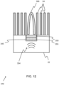
- Figure 1 shows a simulation result of a simplified example of an existing oral treatment unit 10 comprising: a non-conductive, dielectric barrier 12; a first RF electrode 13; and a second RF electrode 14.
- an electric signal in the radio frequency range is provided to the first and second RF electrodes, thereby generating an RF field 15 between the two electrodes.
- the RF field lines cannot pass through the non-conductive barrier 12, the RF field is shaped around the dielectric barrier and redirected/deflected towards the teeth and gums of the user.
- the example of Figure 1 delivers an RF field using three elements: two exposed metallic conductors and one insulator, as well as the non-conducting barrier needed to shape and re-direct the electromagnetic field to go near the teeth.
- Figure 1 requires numerous separate, powered components increasing the complexity of manufacture and requires exposed metal electrical contacts to be positioned within the user's mouth, the latter giving rise to a higher risk of injury or in-mouth discomfort due to mechanically sharp and electrically active exposed elements in the oral cavity.
- the existing solution provides only rough control of the RF field confinement and is prone to electromagnetic energy leakage in the form of radiation.
- a radio frequency (RF) electromagnetic field referred to herein as a RF field
- a RF field proximate to the teeth and gums of a user is subject to size limitations in order to comfortably fit in the oral cavity.
- the invention is defined by the independent claim 1.
- an oral treatment unit for confining an electromagnetic field having a frequency in the range of 100 kHz to 300 MHz and adapted to be inserted into the oral cavity of a user, the oral treatment unit comprising:
- the material structure has one or more of a negative effective permittivity; a negative effective permeability; and a negative refractive index.
- the oral treatment unit provides for focusing an electromagnetic field, for example having a frequency within a radio frequency (RF) range, within the near-field region of the material structure to aid in the cleaning of the user's mouth by producing a confined electromagnetic (EM) field in the region of a user's teeth or gums.
- RF radio frequency
- EM confined electromagnetic
- the focusing function is a property of the material structure
- the shape and focus of the EM field may be adjusted according to any given implementation of the oral treatment unit.
- the material structure comprises a plurality of unit cells, and wherein optionally the unit cells are arranged in an array. In this way, if the dimension of the unit cell is much smaller than the wavelength of the applied EM field, the material structure may act as a single element whose overall electromagnetic properties modify the EM field, and the resultant confinement, distribution and shaping of the EM field, results from the homogenization of individual properties within the unit cells.
- the oral treatment unit further comprises a second cleaning element, and wherein the material structure forms at least part of, or all of, the second cleaning element.
- the material structure may contribute to both mechanical cleaning actions and EM field confinement or shaping, thereby performing a dual function.
- the unit cell comprises a planar conductive spiral structure; or a planar conductive ring structure; or a planar conductive meander line structure; or a 3D conductive spiral structure; or a 3D conductive ring structure; or a 3D conductive meander line structure.
- the EM field received by the material structure may be transformed into an evanescent wave.
- the material structure comprises:
- the oral treatment unit further comprises one or more transmitter coils adapted to generate the initial electromagnetic field to be received by the material structure.
- the oral treatment unit further comprises a multi-harmonic transmitter coil adapted to generate a first electromagnetic field in a first frequency range to be received by the first unit cell and a second electromagnetic field in a second frequency range to be received by the second unit cell.
- the oral treatment unit further comprises a first transmitter coil adapted to generate an electromagnetic field having a first frequency within a first frequency range and a second transmitter coil adapted to generate an electromagnetic field having a first frequency within a second frequency range.
- a coil loop of the transmitter coil and the spiral structure of the unit cell are parallel and/or coaxially aligned. In this way, the coupling between the transmitter coil and the unit cell or material structure is improved.
- the invention provides an oral treatment unit, or an assembly of a plurality of oral treatment units, for confining an electromagnetic field having a frequency in the range of 100 kHz to 300 MHz and adapted to be inserted into an oral cavity, which may form part of an oral cleaning device in combination with a base unit, including a first cleaning element coupled to the oral treatment unit.
- the oral treatment unit further includes a material structure coupled to the oral treatment unit adapted to receive an initial electromagnetic field and output a focused electromagnetic field, wherein the material structure has a passive electromagnetic field focusing function, which focuses the received initial electromagnetic field in the near-field region of the material structure.
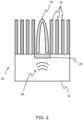
- Figure 2 shows a schematic representation of an oral treatment unit 20 for treating an oral cavity of a user according to the invention.
- the treatment of the oral cavity may include, for example, cleaning any of the teeth, gums or tongue of the user.
- the oral treatment unit 20 comprises a platen 22, which is defined as a foundational piece for receiving a variety of components to form a device, or sub-unit of a device, that may be shaped according to the desired implementation.
- the platen may be flat or curved.
- the oral treatment device comprises one or more cleaning elements 24 coupled to the oral treatment device.
- the oral treatment unit may form part of any suitable oral treatment device, such as a brushing mouthpiece.
- the oral treatment unit may be part of a head of a toothbrush, such as an electric toothbrush, and the cleaning element is a toothbrush bristle.
- Alternative oral treatment units and cleaning elements are described further below.
- the oral treatment unit 20 further comprises a material structure 26, comprising a plurality of unit cells, coupled to the oral treatment device and adapted to receive an electromagnetic field 28 and output a focused electromagnetic field 30.
- the material structure has a passive radio frequency focusing function, which focuses the received radio frequency signal in the near-field region of the material structure.
- the material structure is an example of a so-called metamaterial, and more specifically an electromagnetic metamaterial.
- electromagnetic metamaterials can be designed with tailorable and exotic electromagnetic properties, such as: a negative effective permittivity; a negative effective permeability; and a negative refractive index.
- Metamaterials are an emerging technology and defined as engineered materials governed by their structure, i.e. the geometric arrangement of one or more materials and unit cells, rather than by their composition. Metamaterials may be designed to enable features that are not available in naturally occurring materials, such as negative refractive index. Metamaterials, such as the material structure 26 may consist of an array of unit cells, whose characteristic size is much smaller than the signal wavelengths utilized by the devices described herein as further discussed below. Details regarding example unit cells of the material structure are discussed below with reference to Figure 3 .
- electromagnetic waves and/or fields may be manipulated, by absorbing, blocking, enhancing, bending or reflecting the electromagnetic waves.
- Electromagnetic metamaterials may show negative effective permeability, negative effective permittivity, or negative refractive index, which occurs when the permittivity and permeability of the material structure are both simultaneously negative.
- a negative refractive index is desired for EM field focusing.
- EM field having a frequency in the low MHz radio frequency (RF) range
- RF radio frequency
- only super-resolution in the near-field defined as locations less than one wavelength far from the source, is required.
- only one of the effective electromagnetic properties needs to be negative as this would be sufficient to enhance evanescent waves in order to create the focused RF electromagnetic field.
- electric and magnetic fields are mostly decoupled, thereby, simplifying the material requirements.
- the EM fields of interest to the invention may have a wide range of frequencies, such as from the radiofrequency (RF) range to microwaves, for example from 100 kHz - 300 GHz, the wavelengths are generally long, in the meter range, which is particularly large for small devices, such as oral cleaning devices. Therefore, unit cells of metamaterials may be miniaturized towards dimensions for the deep sub-wavelength region. Wavelength to unit cell size ratios of 2000 up to 14400 are currently possible, enabling miniaturized compact RF metamaterial structures, suitable for oral care devices.
- RF radiofrequency
- Figure 3a shows a schematic representation of an example unit cell 40 from a plan view and a cross sectional view 41 of the material structure shown in Figure 2 .
- Figure 3b shows a simplified version of the corresponding R-L-C equivalent resonant circuit 50 for the unit cell 40 of Figure 3a .
- the characteristics of the unit cell 40 shown in Figure 3a are defined by several characteristic dimensions. These are: the width of the conductive path 42, the spacing between conductive paths, and the side length of the central capacitive pad 44, which can be connected through the full thickness of the dielectric layer 45 to a second central capacitive pad 44 (not shown) at the bottom of the dielectric layer. In some examples, central capacitive pad 44 may not extend through the full thickness of the dielectric layer 45.
- the EM field shaping and focusing effects of metamaterials is due to negative effective electromagnetic parameters, such as negative permeability, induced by internal resonances within the unit cell.
- the internal resonances are defined by the unit cell design, which can equivalently be regarded as the resonant R-L-C circuit shown in Figure 3b , in which the inductance and capacitance are functions of the geometric parameters of the unit cell in addition to the material parameters, including conductivity, permeability and permittivity. Additional geometric parameters that affect the internal resonances of the unit cell include the number of turns, the side length of the square coil, the unit cell size and the distance between different layers of unit cells.
- the unit cell may include a dielectric layer 45 as shown by the cross-sectional view 41.
- the dielectric layer may be formed of any suitable dielectric material.
- the dielectric layer may comprise a glass-reinforced epoxy laminate material.
- the R-L-C circuit shown in Figure 3b corresponds to a quasi-static representation of the unit cell design.
- the inductance L is given by the self-inductance of the spirals
- the capacitance C corresponds to the equivalent capacitance given by the sum of the total distributed capacitance between parallel sidewalls (adjacent turns) and a vertical capacitor formed by two square conductive pads in the middle of the unit cell
- the resistor R corresponds to the total resistance given by the sum of the resistance caused by skin effect, the proximity loss caused by eddy currents, the sheet resistance of the metallic trace and the dielectric loss.
- High-order effects such as capacitive coupling between non-adjacent sidewalls may be assumed to be negligible.
- the unit cell shown in Figure 3a is an example of a planar spiral resonator, which belongs to the group of metamaterials exhibiting a negative effective permeability; however negative dielectric permittivity, or negative refractive may also be realized.
- Examples of deep sub-wavelength metamaterial designs of this type for RF frequency range signals may have a unit cell size a in the order of a ⁇ ⁇ 0 /2000, where ⁇ 0 is the free space wavelength and a is the unit cell characteristic size.
- the free space wavelength for radio frequencies in the range between 3 MHz and 300 GHz is of the order of 1 millimeter to 100 meters.
- metamaterials with unit cells sizes in 0.5 ⁇ m - 50 mm range may be designed, which is an acceptable range for oral cleaning devices, for example within the platen of a toothbrush or a full arch of a mouthpiece. Even smaller unit cell sizes may be designed in the range 0.07 ⁇ m - 7 mm, following the latest manufacturing technology with ⁇ 0 /14400.
- the material structure, or metamaterials, described above, which possess a negative dielectric permittivity ⁇ and/or negative magnetic permeability ⁇ and/or negative refractive index, are considered as passive elements.
- the transmitted RF field, received by the material structure, thereby passing through the metamaterial produces either an evanescent wave, i.e., an oscillating electric and/or magnetic field that does not propagate as an electromagnetic wave but whose energy is spatially concentrated, and in particular within the near-field region of the material structure, or a redirected propagating wave in the case of frequencies in the GHz frequency range as discussed further below.
- metamaterials make use of internally resonant unit cells, as building blocks.
- the underlying physical phenomenon in metamaterials results from the interaction between internal resonance and the incoming electromagnetic wave, as well as the interaction between unit cells, in the form of signal interference. Both interactions combined give rise to a band gap, a frequency band within which evanescent waves occur, promoting wave attenuation.
- Having only one resonator (unit cell) provides only local attenuation (only modal coupling at a particular frequency). Having a collective arrangement of resonators generates global attenuation, and thus a band gap and corresponding evanescent wave is generated.
- the unit cells within the material structures discussed herein may be arranged in a 1D, 2D or 3D periodic arrangement to form a regular array of unit cells.
- in silico models may be used to design and measure the effective properties of proposed metamaterials.
- the in silico designed materials can be manufactured in a straightforward manner using commercially available standard manufacturing technologies such as: thin film manufacturing processes, additive manufacturing and printed circuit board photolithography.
- metamaterials with certain target properties may be designed using existing design processes such as machine learning, which can be used to explore large parametric design spaces and even design metamaterial structures from scratch.
- trial and error parametric exploration may be used to optimize the design within a given set of constraints, such as the design of an initial metamaterial repeating unit with some adjustable parameters.
- New fabrication techniques including 3D printing are enabling fast and cheap production of materials with complex internal structures, including electromagnetic metamaterials.
- the oral treatment unit 20 comprising the material structure 26 as described above, provides shaping and focusing the received radio frequency signal 28 by way of a focusing function implemented, for example, by an array of unit cells as described above.
- the material structure 26 may either transform propagating electromagnetic fields 28 into an evanescent wave, thereby promoting a passive EM field 30, or manipulate/redirect propagating waves, as for instance, promoting negative refraction, and enabling field focusing 30.
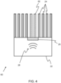
- Figure 4 shows a further example of an oral treatment unit 60 according to an aspect of the invention.
- the oral treatment unit 60 further comprises an additional cleaning element 62, and wherein the material structure 26 is incorporated into the additional cleaning element or wherein the material structure 26 is arranged to form the additional cleaning element 62 itself.
- the metamaterial unit cell or the additional cleaning element 62 comprising the metamaterial structure may perform a dual function: the first being mechanical cleaning alongside the unmodified cleaning elements 24, i.e. bristles; and the second being EM field focusing, by means of a material structure incorporated into the additional cleaning element 62 which may comprise either an elongated out of plane spiral resonator embedded in a dielectric matrix or large diameter (wide) polymeric cleaning elements (e.g. bristles) with planar spiral metamaterial structures printed on top and bottom layers, which may be connected by a conductive wire passing through the length of the additional cleaning element.
- a material structure incorporated into the additional cleaning element 62 which may comprise either an elongated out of plane spiral resonator embedded in a dielectric matrix or large diameter (wide) polymeric cleaning elements (e.g. bristles) with planar spiral metamaterial structures printed on top and bottom layers, which may be connected by a conductive wire passing through the length of the additional cleaning element.
- the basic design of the unit cells of the material structure may be the same as the one shown in Figure 3a .
- a cleaning function is added to the material structure as the metamaterial is directly integrated in a cleaning element, such as a bristle, a silicone pillar, a rubbery pad or a prophy cup.
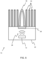
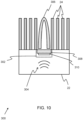
- Figure 5 shows a further example of an oral treatment unit 70 according to an aspect of the invention.
- Reference numerals shared with Figure 2 refer to similar features.
- the oral treatment unit 70 further comprises a transmitter coil 72 adapted to transmit an electromagnetic field 28 to be received by the material structure 26 as described above.
- a transmitter coil which may comprise a single loop or a solenoid, transmitting the electromagnetic field is located within platen of the oral treatment unit.
- the transmitter coil may be integrated into to the oral treatment unit or be temporarily attached to the oral treatment unit.
- the material structure is positioned at a fixed distance from the transmitter coil, typically 0.5-5 mm. The distance may be adjusted to optimize the coupling between the transmitter coil and the material structure.
- the coil loops and the spiral metamaterial may be faced parallel and coaxially to each other and coaxially aligned in one plane to efficiently couple the electromagnetic field into the metamaterial.
- the negative effective properties (permittivity, refractive index and permeability) of the metamaterial minimizes electromagnetic field and energy leakage and promotes better near-field focusing 30 towards the tooth or gum tissue.
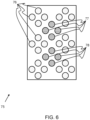
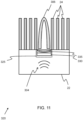
- Figure 6 shows a further example of an oral treatment unit 75 comprising a plurality of cleaning elements 76, an array of first unit cells 77 adapted to receive and confine an electromagnetic field with a first frequency within a first frequency range and an array of second unit cells 78, adapted to receive and confine an electromagnetic field with a second frequency within a second frequency range different from the first frequency range.
- the oral treatment unit or the material structure may comprise one or more arrays of multiple unit cells, each working as an electromagnetic field lens tailored to a different operation frequency, thus promoting multiple operation modes which can be implemented in oral care devices such as toothbrushes and mouthpieces.
- either one multi-harmonic transmitter coil or multiple transmitter coils transmitting the electromagnetic field at multiple frequencies may be incorporated into the oral treatment unit or the base unit.
- the oral treatment unit may include an array of metamaterials configured to provide enhanced EM field confinement for different resonance frequencies, with the possibility of allowing multiple operation modes targeting specific zones in the oral cavity, such as dental calculus, biofilm, stains, gum tissue, pockets, dental implants, orthodontics and the like.
- multiple EM energy levels can be provided on demand, without the need to activate different device operation modes.
- the oral treatment unit may perform a cleaning mode for stain removal, a calculus treatment mode, or a gum health mode for treatment of gingival pockets all of which may require different device settings.
- the oral treatment units described above may be part of or integrated in an electric toothbrush head to be used in combination with a base unit, such as an electric toothbrush handle.
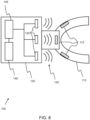
- Figure 7 shows an example of an oral cleaning device 80 according to aspects of the invention, wherein the energy and signal transmission path to a transmitter coil 72 inside the oral treatment unit 70 is indicated by a dotted line.
- the oral cleaning device comprises the oral treatment unit 70 as described above temporarily coupled to a base unit 82, which comprises a power source 84 and an electrical signal generation unit 86 coupled to the power source and adapted to generate an electrical drive signal.
- the base unit further comprises a drive train / transmission technology or actuator to generate the required mechanical motions for cleaning (not shown).
- the oral treatment unit comprises a transmitter coil 72
- the oral treatment unit is adapted to be temporarily coupled to the base unit, and wherein the oral treatment unit further comprises a first electrical contact 88 and the base unit further comprises a second electrical contact 90, wherein the first electrical contact and the second electrical contact are in contact when the oral treatment unit is coupled to the base unit.
- the electrical signal generated by the electrical signal generation unit 86 is provided to the transmitter coil 72 in the oral treatment unit to generate the electromagnetic field 28 to be received by the material structure 26 to produce the output focused EM field 30.
- the base unit 82 may comprise a transmitter coil in communication with the electrical signal generator adapted to transmit the electromagnetic signal to the oral treatment unit. In this case, there is no need for electrical contacts between the oral treatment unit and the base unit and no powered components are required within the oral treatment unit, as the material structure is passive.
- the oral cleaning device has been described in the context of an electrical toothbrush.
- the oral cleaning device may be any oral cleaning device such as a brushing/cleaning or treatment mouthpiece.
- FIG 8 shows an example where the oral cleaning device is a treatment mouthpiece 100, wherein multiple oral treatment units 115 are coupled and arranged to form an arch 110.
- Each of the oral treatment unit 115 as described in detail above with reference to Figures 2 and 4 comprises a material structure adapted to produce a confined electromagnetic field from a received electromagnetic field 120 supplied from a plurality of transmitter coils 130 located in a base unit 135 temporarily coupled to the oral treatment units.
- the base unit 135 further comprises a power supply 140 and signal generator 145 that as described above with reference to Figure 7 .
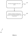
- Figure 9 shows using 200 the oral cleaning device described above.
- the oral treatment unit or a plurality of oral treatment units of the oral cleaning device is provided to the mouth of a user.
- the cleaning elements of the oral treatment unit are used to clean the oral cavity of the user using a mechanical cleaning motion and the electromagnetic signal is transmitted to the material structure of the oral treatment unit, thereby generating a focused radio frequency electromagnetic field in the vicinity of the gum or teeth of the oral cavity of the user to aid in the cleaning process.
- the material structure of the oral cleaning units are adapted to only perform the passive electromagnetic focusing function on the received electromagnetic field.
- the focused electromagnetic fields are preferably in the radio frequency range. Accordingly, the above examples may be adapted to receive an electromagnetic field having a frequency in the radio frequency range, and in particular, the material structure, or the unit cells of the material structure, may be adapted to focus and confine electromagnetic fields with frequencies in the radio frequency range.
- metamaterials adapted to focus electromagnetic fields with a frequency in the range of 1 MHz to 300 GHz with unit cells sizes between 0.5 ⁇ m to 150 mm can be designed with conventional design techniques, or as small as 0.07 ⁇ m to 21 mm with advanced design techniques, which are acceptable ranges for oral treatment devices, for example for placement in a brush head of a toothbrush or the arch of a mouthpiece.
- the advantage of working with electromagnetic fields in the high electromagnetic frequency range instead of in the low electromagnetic frequency range include a reduced form factor and broader range of possible metamaterial designs that would fit inside oral treatment devices; however, EM fields operating at higher frequencies may not be suitable for oral healthcare applications.
- an oral treatment unit may comprise an electromagnetic field focusing element adapted to receive an electromagnetic field having an initial frequency, for example in the GHz frequency range, and output a focused electromagnetic field in the MHz frequency range, for example in the radio frequency range.
- the electromagnetic field focusing element comprises a first material structure, such as those material structures described above, wherein the first material structure has a first passive electromagnetic field focusing function, which confines the received electromagnetic field at a given distance from the first material structure at the initial frequency performing one or more of an attenuation rate control function in the near-field region of the first material structure or a propagation direction modification function on the electromagnetic field.
- the electromagnetic field focusing element then modulates the electromagnetic field by way of a modulation function, thereby generating a modulated, confined electromagnetic field.
- the electromagnetic field focusing element and the modulation function may be implemented in a number of ways, some examples of which are described below. It should be noted that the oral treatment units described below may be incorporated into any of the systems described above.
- the modulation function may be adapted to modulate one or more of a frequency, an amplitude and a phase of the confined electromagnetic field.
- the modulation function comprises a frequency downshift function, which modulates the initial frequency of the confined electromagnetic field, thereby generating a modulated, confined electromagnetic field having a modulated frequency in a desired frequency range lower than the initial frequency.
- the electromagnetic field focusing element may comprise a non-linear electronic component, such as a diode, a plurality of diodes, a MIM device (which is a metal-insulator-metal device which has the function of a back-to-back diode) a transistor or a passive transistor, adapted to perform the frequency modulation function on the received electromagnetic field.
- a non-linear electronic component such as a diode, a plurality of diodes, a MIM device (which is a metal-insulator-metal device which has the function of a back-to-back diode) a transistor or a passive transistor, adapted to perform the frequency modulation function on the received electromagnetic field.
- Figure 10 shows a schematic representation of an oral treatment unit 300 for treating an oral cavity of a user according to an aspect of the invention.
- the treatment of the oral cavity may include, for example, cleaning any of the teeth, gums or tongue of the user.
- the oral treatment unit 300 comprises a platen 22 and one or more cleaning elements 24 coupled to the oral treatment unit.
- the platen is defined as a foundational piece for receiving a variety of components to form a device, or sub-unit of a device, that may be shaped according to the desired implementation.
- the platen may be flat or curved.
- the oral treatment unit may form part of any suitable oral treatment device, such as a brushing mouthpiece.
- the oral treatment unit may be part of a head of a toothbrush, such as an electric toothbrush, and the cleaning element is a toothbrush bristle.
- Alternative oral treatment units and cleaning elements are described further below.
- the oral treatment unit 300 further comprises an electromagnetic field focusing element 302 adapted to receive an electromagnetic field 304 having an initial frequency and output a focused, modulated electromagnetic field 306.
- the electromagnetic field focusing element 302 comprises a material structure 308, comprising a plurality of unit cells, adapted to receive the electromagnetic field and output a focused electromagnetic field 306.
- the material structure has a passive electromagnetic focusing function, which focuses the received electromagnetic field in the near-field region of the material structure by way of field attenuation control or, alternatively, by redirecting propagating electromagnetic waves, thereby promoting negative refraction and electromagnetic field focusing.
- the electromagnetic field focusing element 302 comprises a mechanical actuator 310 such as a capacitive micromachined ultrasonic transducer (CMUT), a ferroelectric polymer actuator, an electro-active polymer, a vibrator or a digital mirror device, for performing the modulation function, wherein the mechanical actuator is adapted to impart a mechanical oscillation to the first material structure 308.
- the mechanical oscillations imparted on the first material structure by the mechanical actuator cause the internal resonance of the material structure, or unit cells of the material structure, to shift according to the frequency of the mechanical oscillations.
- the frequency, amplitude or phase of the confined electromagnetic field may be modulated according to the frequency of the mechanical oscillations.
- the phase of the confined electromagnetic field may be modulated by providing two mechanical oscillators each imparting mechanical oscillations on the first material structure.
- one or more transmitter coils located either in the oral treatment unit or a coupled base unit as described above, are used to generate and radiate a high frequency electromagnetic field, for example in the GHz range, with two frequency components very close to each other.
- This electromagnetic field impinges on the material structure 308 that coupled to a mechanical actuator 310 or hybrid part comprising a metamaterial integrated into the mechanical actuator itself.
- the role of the material structure is to modify the electromagnetic field either by controlling the attenuation rate in the case where an evanescent field is generated or of the focus distance in the case where a backward wave is generated.
- the mechanical actuator may operate in the MHz range, and modifies the internal resonance of the unit cells making up the material structure, thereby providing a modulation of the electromagnetic field confined by the material structure.
- one or more metamaterial unit cells may be actuated mechanically in order to enable low-frequency, for example in the MHz range, electromagnetic field control and focusing at a controlled distance.
- the mechanical actuator may have non-linear performance, for example by design or by including an additional electric diode component.
- Suitable mechanical actuators may include piezoelectric elements, as these crystalline actuators are one of the few solid state (non-MEMS) actuators which are able to vibrate in the desired frequency range, i.e. the radio frequency, MHz range.
- non-MEMS solid state actuators
- an array of piezo actuators may be placed under the material structure and actuated at the required MHz frequencies.
- the linear actuation distance may be smaller than required unless the actuators are large enough. Consequently, the form factor of the electromagnetic field focusing element may be larger than is ideal for incorporating into the oral treatment unit.
- mechanical actuators having a very compact form for example bending style actuators that comprise a double layer structure of a thin piezo layer on top of a thin substrate, are available.
- a large actuation distance is achieved by a bend perpendicular to the actuator, resulting from a much smaller linear expansion of the piezo layer compared to the fixed substrate.
- the material structure 308 is positioned at a fixed distance from the transmitter coil and the coil loops and the unit cells of the material structure may be faced parallel to each other and coaxially aligned in one plane to efficiently couple the electromagnetic field into the material structure.
- the material structure minimizes field leakage and provides a controllable electromagnetic field focusing towards the tooth or gum tissue, whereas the mechanical actuator coupled to the electromagnetic metamaterial provides signal modulation to deliver a controllable, modulated electromagnetic field.
- the material structure may further be incorporated into a cleaning element.
- the mechanical actuator 310 may comprise a micro-electrical-mechanical system (MEMS) tilting motion device, such as a Digital Mirror Device (DMD), which controls the position of a small mirror using electrostatic forces generated by electrodes.
- MEMS micro-electrical-mechanical system
- DMD Digital Mirror Device
- the DMD may be positioned below the material structure to form a very thin form factor electromagnetic field focusing element, which may be incorporated into the platen of the oral treatment unit.
- the material structure may be supported by the DMD, or alternatively deposited on top of the DMD, and caused to vibrate at a MHz frequency, which is achieved by causing the mirror to rapidly tilt backwards and forwards.
- Figure 11 shows an example of an oral treatment unit 320 comprising an electromagnetic field focusing element 325 as described above, wherein the mechanical actuator 330 comprises a CMUT cell, having a membrane 335 wherein the first material structure is partially, or fully, incorporated into the membrane.
- the hybrid meta-CMUT cell comprising metamaterial unit cells and enabled for bending-type mechanical actuation may be adapted to have non-linear actuation, for example by design or by an additional electric diode component.
- the principle of incorporating the material structure into the membrane of a CMUT may be applied to any suitable type of bending-based actuator, such as a CMUT cell, a ferroelectric polymer or an electroactive polymer (EAP).
- the mechanical oscillations imparted to the material structure modulate the electromagnetic field by causing a shift in the internal resonance of the unit cells.
- Figure 12 shows an example of an oral treatment unit 340 with an electromagnetic field focusing element 345 comprising a first material structure 350 and a second material structure 355.
- the first material structure has a first passive electromagnetic field focusing function.
- the second material structure has a second passive electromagnetic field focusing function and the first and second focusing functions may be tuned to act on different frequencies, such as a first and second frequency components of the received electromagnetic field, respectively.
- one or more transmitter coil may be used to generate and radiate a high frequency electromagnetic field, for example in the GHz range, with two frequency components very close to each other.
- the first and second material structures within the electromagnetic field focusing element confine and focus the electromagnetic output field 306 for each of the two frequency components that mix to form the modulated electromagnetic field, either by generating evanescent fields with controllable attenuation rates or by modifying the propagation direction of the electromagnetic waves, for example via backward wave generation, thereby providing depth focus distance control.
- the oral treatment unit may comprise two material structures, each composed of one or more unit cells designed to target one of the two frequency components of the received electromagnetic field, which are stacked adjacent to each other and provide low-frequency, for example in the radio frequency range, electromagnetic field confinement and focusing.
- a stack of material structures tuned at different frequencies may operate as delay lines and be used to generate new time-domain waveforms that act on the electromagnetic field, such as a square wave for delivering electromagnetic impulses with a duty cycle.
- an electromagnetic field focusing element comprising a first material structure adapted to operate on a first frequency component of the electromagnetic field and a second material structure adapted to operate on a second frequency component of the electromagnetic field
- an electromagnetic field focusing element comprising a single material structure adapted to operate on both the first and second frequency components may achieve similar results.
- a material structure may have a first passive electromagnetic field focusing function and a second passive electromagnetic field focusing function, wherein the first passive electromagnetic field focusing function acts on a first frequency component of the received electromagnetic field and the second passive electromagnetic field focusing function acts on a second frequency component of the received electromagnetic field.
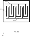
- Figure 13 shows an example of a unit cell 360 of a material structure capable of operating on a first frequency component and a second frequency component of an electromagnetic field.
- the unit cell 360 comprises a central conductor 365, a first conductor 370 and a second conductor 375.
- the first and second conductors have different spacing between themselves and the central conductor, meaning that the unit cell will have two different internal resonance frequencies, one for the first conductor (which acts on the first frequency component) and one for the second conductor (which acts on the second frequency component).
- Figure 14 shows a method 400 for using the oral cleaning device comprising an electromagnetic field focusing element as described above.
- the method is not part of the claimed invention.
- the oral treatment unit or a plurality of oral treatment units of the oral cleaning device is provided to the mouth of a user.
- the cleaning elements of the oral treatment unit are used to clean the oral cavity of the user using a mechanical cleaning motion and the initial electromagnetic field is transmitted to the electromagnetic field focusing element of the oral treatment unit, thereby generating a focused, modulated electromagnetic field in the vicinity of the gum or teeth of the oral cavity of the user to aid in the cleaning process.
Landscapes
- Health & Medical Sciences (AREA)
- Dentistry (AREA)
- General Health & Medical Sciences (AREA)
- Epidemiology (AREA)
- Life Sciences & Earth Sciences (AREA)
- Animal Behavior & Ethology (AREA)
- Public Health (AREA)
- Veterinary Medicine (AREA)
- Physics & Mathematics (AREA)
- Optics & Photonics (AREA)
- Brushes (AREA)
- Dental Tools And Instruments Or Auxiliary Dental Instruments (AREA)
Claims (14)
- Mundbehandlungsvorrichtung (80, 100), die eine Mundbehandlungseinheit (20, 60, 70) zum Eindämmen eines elektromagnetischen Felds, das eine Frequenz im Bereich von 100 kHz bis 300 MHz aufweist, und die dazu eingerichtet ist, in eine Mundhöhle eingeführt zu werden, und eine Basiseinheit (82, 135), die dazu eingerichtet ist, in Kombination mit der Mundbehandlungseinheit verwendet zu werden, umfasst, wobei die Mundbehandlungseinheit Folgendes umfasst:ein erstes Reinigungselement (24), das an die Mundbehandlungseinheit gekoppelt oder in diese integriert ist; undeine Metamaterialstruktur (26), die an die Mundbehandlungseinheit gekoppelt oder in diese integriert und dazu eingerichtet ist, ein anfängliches elektromagnetisches Feld (28) zu empfangen und ein fokussiertes elektromagnetisches Feld auszugeben, wobei die Metamaterialstruktur (26) eines oder mehreres aufweist von:einer negativen effektiven Permittivität;einer negativen effektiven Permeabilität; undeinem negativen Brechungsindex,und wobei die Metamaterialstruktur eine passive elektromagnetische Feldfokussierungsfunktion aufweist, die das empfangene anfängliche elektromagnetische Feld in den Nahfeldbereich der Metamaterialstruktur eindämmt, wobei die Metamaterialstruktur (26) eine Anordnung von Einheitszellen umfasst.
- Mundbehandlungsvorrichtung (100) nach Anspruch 1, wobei die Einheitszellen in einem Array angeordnet sind.
- Mundbehandlungsvorrichtung (100) nach Anspruch 1 oder 2, wobei jede Einheitszelle Folgendes umfasst:eine planare leitfähige Spiralstruktur; odereine planare leitfähige Ringstruktur; odereine planare leitfähige Mäanderlinienstruktur; odereine leitfähige 3D-Spiralstruktur; odereine leitfähige 3D-Ringstruktur; odereine leitfähige 3D-Mäanderlinienstruktur.
- Mundbehandlungsvorrichtung (100) nach einem der Ansprüche 1 bis 3, wobei die Mundbehandlungseinheit (60) weiter ein zweites Reinigungselement (62) umfasst, und wobei die Metamaterialstruktur mindestens einen Teil des oder das gesamte zweite Reinigungselement bildet.
- Mundbehandlungsvorrichtung (100) nach einem der Ansprüche 1 bis 4, wobei die Metamaterialstruktur (26) Folgendes umfasst:eine erste Einheitszelle, die dazu eingerichtet ist, ein erstes elektromagnetisches Feld, das eine erste Frequenz innerhalb eines ersten Frequenzbereichs aufweist, zu empfangen und zu fokussieren; undeine zweite Einheitszelle, die dazu eingerichtet ist, ein zweites elektromagnetisches Feld, das eine zweite Frequenz innerhalb eines zweiten Frequenzbereichs aufweist, der sich von dem ersten Frequenzbereich unterscheidet, zu empfangen und zu fokussieren.
- Mundbehandlungsvorrichtung (80) nach einem der Ansprüche 1 bis 5, wobei die Mundbehandlungseinheit (70) weiter eine oder mehrere Übertragungsspulen (72) umfasst, die dazu eingerichtet sind, das anfängliche elektromagnetische Feld zu erzeugen, das durch die Materialstruktur (26) zu empfangen ist.
- Mundbehandlungsvorrichtung (80) nach Anspruch 5, wobei die Mundbehandlungseinheit (70) weiter eine multiharmonische Übertragungsspule umfasst, die dazu eingerichtet ist, ein erstes elektromagnetisches Feld in einem ersten Frequenzbereich, das durch die erste Einheitszelle zu empfangen ist, und ein zweites elektromagnetisches Feld in einem zweiten Frequenzbereich, das durch die zweite Einheitszelle zu empfangen ist, zu erzeugen.
- Mundbehandlungsvorrichtung (80) nach Anspruch 5, wobei die Mundbehandlungseinheit (70) weiter eine erste Übertragungsspule, die dazu eingerichtet ist, ein elektromagnetischen Feld, das eine erste Frequenz innerhalb eines ersten Frequenzbereichs aufweist, zu erzeugen, und eine zweite Übertragungsspule umfasst, die dazu eingerichtet ist, ein elektromagnetisches Feld, das eine erste Frequenz innerhalb eines zweiten Frequenzbereichs aufweist, zu erzeugen.
- Mundbehandlungsvorrichtung (80) nach einem der Ansprüche 6 bis 8, wobei die Einheitszelle eine Spiralstruktur aufweist und wobei eine Spulenschleife der einen oder mehreren Übertragungsspulen (72) und die Spiralstruktur der Einheitszelle parallel und/oder koaxial ausgerichtet sind.
- Mundbehandlungsvorrichtung (100) nach einem der Ansprüche 1 bis 5, wobei die Basiseinheit (135) Folgendes umfasst:eine Stromquelle (140);eine Einheit (145) zum Erzeugen eines elektrischen Signals, die an die Stromquelle gekoppelt und dazu eingerichtet ist, ein elektrisches Signal zu erzeugen, das eine Frequenz in einem gegebenen Frequenzbereich aufweist; undeine oder mehrere Übertragungsspulen (130) in Kommunikation mit dem elektrischen Signalerzeuger, die dazu eingerichtet sind, mindestens ein elektromagnetisches Feld, das eine Frequenz innerhalb des gegebenen Frequenzbereichs aufweist, zu erzeugen und an die Mundbehandlungseinheit zu übertragen.
- Mundbehandlungsvorrichtung (100) nach Anspruch 10,
wobei die Mundbehandlungseinheit dazu eingerichtet ist, vorübergehend an die Basiseinheit gekoppelt zu werden. - Mundbehandlungsvorrichtung (80) nach einem der Ansprüche 6 bis 9, wobei die Basiseinheit (82) Folgendes umfasst:eine Stromquelle (84);eine Einheit (86) zur Erzeugung eines elektrischen Signals, die an die Stromquelle gekoppelt und dazu eingerichtet ist, ein elektrisches Antriebssignal zu erzeugen, das eine Frequenz in einem gegebenen Frequenzbereich aufweist, das die eine oder mehreren Übertragungsspulen (72) der Mundbehandlungseinheit speist.
- Mundbehandlungsvorrichtung (80) nach Anspruch 12,
wobei die Mundbehandlungseinheit dazu eingerichtet ist, vorübergehend an die Basiseinheit gekoppelt zu werden, und wobei die Mundbehandlungseinheit weiter einen ersten elektrischen Kontakt (88) umfasst und die Basiseinheit weiter einen zweiten elektrischen Kontakt (90) umfasst, wobei der erste elektrische Kontakt und der zweite elektrische Kontakt in Kontakt sind, wenn die Mundbehandlungseinheit an die Basiseinheit gekoppelt ist. - Mundreinigungsvorrichtung (80) nach einem der Ansprüche 1 bis 13, wobei:die Mundbehandlungseinheit ein elektrischer Zahnbürstenkopf oder ein Teil eines elektrischen Zahnbürstenkopfs ist, wobei der elektrische Zahnbürstenkopf vorzugsweise eine Fluidabgabedüse umfasst und wobei die Basiseinheit ein elektrischer Zahnbürstengriff ist; odereine oder mehrere Mundbehandlungseinheiten dazu angeordnet sind, mindestens einen Teil eines Bogens eines Mundbehandlungsmundstücks zu bilden, und wobei die Basiseinheit ein elektrischer Mundstückgriff ist.
Applications Claiming Priority (2)
| Application Number | Priority Date | Filing Date | Title |
|---|---|---|---|
| EP20176971.8A EP3915513A1 (de) | 2020-05-28 | 2020-05-28 | Mundbehandlungsvorrichtung |
| PCT/EP2021/063398 WO2021239548A1 (en) | 2020-05-28 | 2021-05-20 | An oral treatment device |
Publications (3)
| Publication Number | Publication Date |
|---|---|
| EP4157142A1 EP4157142A1 (de) | 2023-04-05 |
| EP4157142C0 EP4157142C0 (de) | 2024-09-18 |
| EP4157142B1 true EP4157142B1 (de) | 2024-09-18 |
Family
ID=70918250
Family Applications (2)
| Application Number | Title | Priority Date | Filing Date |
|---|---|---|---|
| EP20176971.8A Withdrawn EP3915513A1 (de) | 2020-05-28 | 2020-05-28 | Mundbehandlungsvorrichtung |
| EP21726657.6A Active EP4157142B1 (de) | 2020-05-28 | 2021-05-20 | Mundbehandlungsvorrichtung |
Family Applications Before (1)
| Application Number | Title | Priority Date | Filing Date |
|---|---|---|---|
| EP20176971.8A Withdrawn EP3915513A1 (de) | 2020-05-28 | 2020-05-28 | Mundbehandlungsvorrichtung |
Country Status (5)
| Country | Link |
|---|---|
| US (1) | US20230200527A1 (de) |
| EP (2) | EP3915513A1 (de) |
| JP (1) | JP7601907B2 (de) |
| CN (1) | CN115666443A (de) |
| WO (1) | WO2021239548A1 (de) |
Families Citing this family (1)
| Publication number | Priority date | Publication date | Assignee | Title |
|---|---|---|---|---|
| EP3915436A1 (de) | 2020-05-28 | 2021-12-01 | Koninklijke Philips N.V. | Mundbehandlungsvorrichtung |
Family Cites Families (12)
| Publication number | Priority date | Publication date | Assignee | Title |
|---|---|---|---|---|
| US3375820A (en) * | 1965-12-15 | 1968-04-02 | Cavitron Corp | Method and apparatus for ultrasonic cleaning of teeth |
| JP4264128B2 (ja) * | 1999-12-20 | 2009-05-13 | 有限会社 ミクロデント | 光診査装置 |
| US7335199B2 (en) * | 2000-02-22 | 2008-02-26 | Rhytec Limited | Tissue resurfacing |
| WO2010023582A1 (en) * | 2008-08-25 | 2010-03-04 | Koninklijke Philips Electronics, N.V. | System for detection, treatment and coverage feedback of oral health conditions |
| US10992185B2 (en) * | 2012-07-06 | 2021-04-27 | Energous Corporation | Systems and methods of using electromagnetic waves to wirelessly deliver power to game controllers |
| US20160228177A1 (en) * | 2013-09-09 | 2016-08-11 | Syneron Medical Ltd. | A system for periodontal treatment |
| CN105813503B (zh) * | 2013-12-18 | 2018-05-18 | 高露洁-棕榄公司 | 牙刷 |
| US20160228720A1 (en) * | 2015-02-11 | 2016-08-11 | Elwha LLC, a limited liability company of the State of Delaware | Electromagnetic field perturbing object having a biocompatible exterior surface and a selected dielectric permittivity value or a selected magnetic permeability value |
| US10201701B2 (en) * | 2015-03-29 | 2019-02-12 | Home Skinovations Ltd. | Oral electrical cleaning device |
| US10312597B2 (en) * | 2015-09-25 | 2019-06-04 | The Boeing Company | Ferrite-enhanced metamaterials |
| EP3528853B1 (de) * | 2016-10-19 | 2023-01-11 | Colgate-Palmolive Company | Mundpflegegerät sanitisationssystem |
| US20210307888A1 (en) * | 2018-09-07 | 2021-10-07 | Water Pik, Inc. | Cleansing attachment for oral cleansing device |
-
2020
- 2020-05-28 EP EP20176971.8A patent/EP3915513A1/de not_active Withdrawn
-
2021
- 2021-05-20 EP EP21726657.6A patent/EP4157142B1/de active Active
- 2021-05-20 WO PCT/EP2021/063398 patent/WO2021239548A1/en not_active Ceased
- 2021-05-20 CN CN202180038443.8A patent/CN115666443A/zh active Pending
- 2021-05-20 JP JP2022572344A patent/JP7601907B2/ja active Active
- 2021-05-20 US US17/927,355 patent/US20230200527A1/en not_active Abandoned
Also Published As
| Publication number | Publication date |
|---|---|
| JP2023526993A (ja) | 2023-06-26 |
| EP4157142A1 (de) | 2023-04-05 |
| WO2021239548A1 (en) | 2021-12-02 |
| EP4157142C0 (de) | 2024-09-18 |
| EP3915513A1 (de) | 2021-12-01 |
| JP7601907B2 (ja) | 2024-12-17 |
| CN115666443A (zh) | 2023-01-31 |
| US20230200527A1 (en) | 2023-06-29 |
Similar Documents
| Publication | Publication Date | Title |
|---|---|---|
| JP6360487B2 (ja) | 複数の高調波モードを有するマイクロ機械加工超音波変換器アレイ | |
| Meng et al. | Design and optimization of ultrasonic wireless power transmission links for millimeter-sized biomedical implants | |
| Jiang et al. | Multichannel piezo‐ultrasound implant with hybrid waterborne acoustic metastructure for selective wireless energy transfer at megahertz frequencies | |
| Kashani et al. | Design and optimization of ultrasonic links with phased arrays for wireless power transmission to biomedical implants | |
| CN103008218B (zh) | 一种用于超声探头的构造中的复合陶瓷换能器结构 | |
| CN115151350A (zh) | 声学换能器结构 | |
| US20110257532A1 (en) | Ultrasonic probe and method of preparing ultrasonic probe | |
| EP4157142B1 (de) | Mundbehandlungsvorrichtung | |
| KR102472295B1 (ko) | 초음파 변환기 | |
| JP2008009435A (ja) | 光ファイバ上に屈曲波を励起するアクチュエータ | |
| EP4157034B1 (de) | Mundbehandlungseinheit und entsprechende mundbehandlungsvorrichtung | |
| CN118298794A (zh) | 一种可调控声学透射/反射螺旋聚焦透镜 | |
| CN115697135B (zh) | 口腔清洁和/或处理装置及其配置方法 | |
| JPWO2021239548A5 (de) | ||
| KR20190045531A (ko) | 선집속 초음파 트랜스듀서 및 이를 포함하는 고강도 선집속 초음파 구동장치 | |
| Song et al. | Up-and-coming physical concepts of wireless power transfer | |
| US20240082876A1 (en) | Imaging devices having piezoelectric transceivers with harmonic characteristics | |
| JP5605567B2 (ja) | アレイ型超音波送波器 | |
| KR101299966B1 (ko) | 고출력 초음파 프로브 | |
| JP7316924B2 (ja) | 超音波放射器具及び超音波装置 | |
| KR102080258B1 (ko) | 고강도 선집속 초음파 구동시스템 | |
| WO2022211836A1 (en) | Imaging devices having piezoelectric transceivers with harmonic characteristics |
Legal Events
| Date | Code | Title | Description |
|---|---|---|---|
| STAA | Information on the status of an ep patent application or granted ep patent |
Free format text: STATUS: UNKNOWN |
|
| STAA | Information on the status of an ep patent application or granted ep patent |
Free format text: STATUS: THE INTERNATIONAL PUBLICATION HAS BEEN MADE |
|
| PUAI | Public reference made under article 153(3) epc to a published international application that has entered the european phase |
Free format text: ORIGINAL CODE: 0009012 |
|
| STAA | Information on the status of an ep patent application or granted ep patent |
Free format text: STATUS: REQUEST FOR EXAMINATION WAS MADE |
|
| 17P | Request for examination filed |
Effective date: 20230102 |
|
| AK | Designated contracting states |
Kind code of ref document: A1 Designated state(s): AL AT BE BG CH CY CZ DE DK EE ES FI FR GB GR HR HU IE IS IT LI LT LU LV MC MK MT NL NO PL PT RO RS SE SI SK SM TR |
|
| DAV | Request for validation of the european patent (deleted) | ||
| DAX | Request for extension of the european patent (deleted) | ||
| STAA | Information on the status of an ep patent application or granted ep patent |
Free format text: STATUS: EXAMINATION IS IN PROGRESS |
|
| 17Q | First examination report despatched |
Effective date: 20231128 |
|
| GRAP | Despatch of communication of intention to grant a patent |
Free format text: ORIGINAL CODE: EPIDOSNIGR1 |
|
| STAA | Information on the status of an ep patent application or granted ep patent |
Free format text: STATUS: GRANT OF PATENT IS INTENDED |
|
| INTG | Intention to grant announced |
Effective date: 20240419 |
|
| GRAS | Grant fee paid |
Free format text: ORIGINAL CODE: EPIDOSNIGR3 |
|
| GRAA | (expected) grant |
Free format text: ORIGINAL CODE: 0009210 |
|
| STAA | Information on the status of an ep patent application or granted ep patent |
Free format text: STATUS: THE PATENT HAS BEEN GRANTED |
|
| AK | Designated contracting states |
Kind code of ref document: B1 Designated state(s): AL AT BE BG CH CY CZ DE DK EE ES FI FR GB GR HR HU IE IS IT LI LT LU LV MC MK MT NL NO PL PT RO RS SE SI SK SM TR |
|
| REG | Reference to a national code |
Ref country code: GB Ref legal event code: FG4D |
|
| REG | Reference to a national code |
Ref country code: CH Ref legal event code: EP |
|
| REG | Reference to a national code |
Ref country code: IE Ref legal event code: FG4D |
|
| REG | Reference to a national code |
Ref country code: DE Ref legal event code: R096 Ref document number: 602021018987 Country of ref document: DE |
|
| U01 | Request for unitary effect filed |
Effective date: 20240918 |
|
| U07 | Unitary effect registered |
Designated state(s): AT BE BG DE DK EE FI FR IT LT LU LV MT NL PT RO SE SI Effective date: 20241010 |
|
| PG25 | Lapsed in a contracting state [announced via postgrant information from national office to epo] |
Ref country code: NO Free format text: LAPSE BECAUSE OF FAILURE TO SUBMIT A TRANSLATION OF THE DESCRIPTION OR TO PAY THE FEE WITHIN THE PRESCRIBED TIME-LIMIT Effective date: 20241218 |
|
| PG25 | Lapsed in a contracting state [announced via postgrant information from national office to epo] |
Ref country code: GR Free format text: LAPSE BECAUSE OF FAILURE TO SUBMIT A TRANSLATION OF THE DESCRIPTION OR TO PAY THE FEE WITHIN THE PRESCRIBED TIME-LIMIT Effective date: 20241219 |
|
| PG25 | Lapsed in a contracting state [announced via postgrant information from national office to epo] |
Ref country code: HR Free format text: LAPSE BECAUSE OF FAILURE TO SUBMIT A TRANSLATION OF THE DESCRIPTION OR TO PAY THE FEE WITHIN THE PRESCRIBED TIME-LIMIT Effective date: 20240918 |
|
| PG25 | Lapsed in a contracting state [announced via postgrant information from national office to epo] |
Ref country code: RS Free format text: LAPSE BECAUSE OF FAILURE TO SUBMIT A TRANSLATION OF THE DESCRIPTION OR TO PAY THE FEE WITHIN THE PRESCRIBED TIME-LIMIT Effective date: 20241218 |
|
| PG25 | Lapsed in a contracting state [announced via postgrant information from national office to epo] |
Ref country code: RS Free format text: LAPSE BECAUSE OF FAILURE TO SUBMIT A TRANSLATION OF THE DESCRIPTION OR TO PAY THE FEE WITHIN THE PRESCRIBED TIME-LIMIT Effective date: 20241218 Ref country code: NO Free format text: LAPSE BECAUSE OF FAILURE TO SUBMIT A TRANSLATION OF THE DESCRIPTION OR TO PAY THE FEE WITHIN THE PRESCRIBED TIME-LIMIT Effective date: 20241218 Ref country code: HR Free format text: LAPSE BECAUSE OF FAILURE TO SUBMIT A TRANSLATION OF THE DESCRIPTION OR TO PAY THE FEE WITHIN THE PRESCRIBED TIME-LIMIT Effective date: 20240918 Ref country code: GR Free format text: LAPSE BECAUSE OF FAILURE TO SUBMIT A TRANSLATION OF THE DESCRIPTION OR TO PAY THE FEE WITHIN THE PRESCRIBED TIME-LIMIT Effective date: 20241219 |
|
| PG25 | Lapsed in a contracting state [announced via postgrant information from national office to epo] |
Ref country code: IS Free format text: LAPSE BECAUSE OF FAILURE TO SUBMIT A TRANSLATION OF THE DESCRIPTION OR TO PAY THE FEE WITHIN THE PRESCRIBED TIME-LIMIT Effective date: 20250118 |
|
| PG25 | Lapsed in a contracting state [announced via postgrant information from national office to epo] |
Ref country code: SM Free format text: LAPSE BECAUSE OF FAILURE TO SUBMIT A TRANSLATION OF THE DESCRIPTION OR TO PAY THE FEE WITHIN THE PRESCRIBED TIME-LIMIT Effective date: 20240918 |
|
| PG25 | Lapsed in a contracting state [announced via postgrant information from national office to epo] |
Ref country code: ES Free format text: LAPSE BECAUSE OF FAILURE TO SUBMIT A TRANSLATION OF THE DESCRIPTION OR TO PAY THE FEE WITHIN THE PRESCRIBED TIME-LIMIT Effective date: 20240918 |
|
| PG25 | Lapsed in a contracting state [announced via postgrant information from national office to epo] |
Ref country code: PL Free format text: LAPSE BECAUSE OF FAILURE TO SUBMIT A TRANSLATION OF THE DESCRIPTION OR TO PAY THE FEE WITHIN THE PRESCRIBED TIME-LIMIT Effective date: 20240918 Ref country code: CZ Free format text: LAPSE BECAUSE OF FAILURE TO SUBMIT A TRANSLATION OF THE DESCRIPTION OR TO PAY THE FEE WITHIN THE PRESCRIBED TIME-LIMIT Effective date: 20240918 |
|
| PG25 | Lapsed in a contracting state [announced via postgrant information from national office to epo] |
Ref country code: SK Free format text: LAPSE BECAUSE OF FAILURE TO SUBMIT A TRANSLATION OF THE DESCRIPTION OR TO PAY THE FEE WITHIN THE PRESCRIBED TIME-LIMIT Effective date: 20240918 |
|
| U20 | Renewal fee for the european patent with unitary effect paid |
Year of fee payment: 5 Effective date: 20250602 |
|
| PGFP | Annual fee paid to national office [announced via postgrant information from national office to epo] |
Ref country code: GB Payment date: 20250520 Year of fee payment: 5 |
|
| PLBE | No opposition filed within time limit |
Free format text: ORIGINAL CODE: 0009261 |
|
| STAA | Information on the status of an ep patent application or granted ep patent |
Free format text: STATUS: NO OPPOSITION FILED WITHIN TIME LIMIT |
|
| 26N | No opposition filed |
Effective date: 20250619 |