EP4156901B1 - Système d'ancrage - Google Patents
Système d'ancrage Download PDFInfo
- Publication number
- EP4156901B1 EP4156901B1 EP21727233.5A EP21727233A EP4156901B1 EP 4156901 B1 EP4156901 B1 EP 4156901B1 EP 21727233 A EP21727233 A EP 21727233A EP 4156901 B1 EP4156901 B1 EP 4156901B1
- Authority
- EP
- European Patent Office
- Prior art keywords
- support assembly
- assembly according
- arrangement
- support
- tendon arrangement
- Prior art date
- Legal status (The legal status is an assumption and is not a legal conclusion. Google has not performed a legal analysis and makes no representation as to the accuracy of the status listed.)
- Active
Links
Images


Classifications
-
- E—FIXED CONSTRUCTIONS
- E02—HYDRAULIC ENGINEERING; FOUNDATIONS; SOIL SHIFTING
- E02D—FOUNDATIONS; EXCAVATIONS; EMBANKMENTS; UNDERGROUND OR UNDERWATER STRUCTURES
- E02D5/00—Bulkheads, piles, or other structural elements specially adapted to foundation engineering
- E02D5/74—Means for anchoring structural elements or bulkheads
- E02D5/80—Ground anchors
-
- A—HUMAN NECESSITIES
- A01—AGRICULTURE; FORESTRY; ANIMAL HUSBANDRY; HUNTING; TRAPPING; FISHING
- A01G—HORTICULTURE; CULTIVATION OF VEGETABLES, FLOWERS, RICE, FRUIT, VINES, HOPS OR SEAWEED; FORESTRY; WATERING
- A01G17/00—Cultivation of hops, vines, fruit trees, or like trees
- A01G17/04—Supports for hops, vines, or trees
-
- E—FIXED CONSTRUCTIONS
- E02—HYDRAULIC ENGINEERING; FOUNDATIONS; SOIL SHIFTING
- E02D—FOUNDATIONS; EXCAVATIONS; EMBANKMENTS; UNDERGROUND OR UNDERWATER STRUCTURES
- E02D5/00—Bulkheads, piles, or other structural elements specially adapted to foundation engineering
- E02D5/74—Means for anchoring structural elements or bulkheads
- E02D5/80—Ground anchors
- E02D5/803—Ground anchors with pivotable anchoring members
-
- E—FIXED CONSTRUCTIONS
- E04—BUILDING
- E04H—BUILDINGS OR LIKE STRUCTURES FOR PARTICULAR PURPOSES; SWIMMING OR SPLASH BATHS OR POOLS; MASTS; FENCING; TENTS OR CANOPIES, IN GENERAL
- E04H12/00—Towers; Masts or poles; Chimney stacks; Water-towers; Methods of erecting such structures
- E04H12/20—Side-supporting means therefor, e.g. using guy ropes or struts
-
- E—FIXED CONSTRUCTIONS
- E04—BUILDING
- E04H—BUILDINGS OR LIKE STRUCTURES FOR PARTICULAR PURPOSES; SWIMMING OR SPLASH BATHS OR POOLS; MASTS; FENCING; TENTS OR CANOPIES, IN GENERAL
- E04H17/00—Fencing, e.g. fences, enclosures, corrals
- E04H17/14—Fences constructed of rigid elements, e.g. with additional wire fillings or with posts
- E04H17/20—Posts therefor
- E04H17/23—Posts therefor lateral supporting elements, e.g. braces, tie downs, or cables
-
- D—TEXTILES; PAPER
- D07—ROPES; CABLES OTHER THAN ELECTRIC
- D07B—ROPES OR CABLES IN GENERAL
- D07B1/00—Constructional features of ropes or cables
- D07B1/18—Grommets
-
- D—TEXTILES; PAPER
- D07—ROPES; CABLES OTHER THAN ELECTRIC
- D07B—ROPES OR CABLES IN GENERAL
- D07B1/00—Constructional features of ropes or cables
- D07B1/18—Grommets
- D07B1/185—Grommets characterised by the eye construction
-
- E—FIXED CONSTRUCTIONS
- E02—HYDRAULIC ENGINEERING; FOUNDATIONS; SOIL SHIFTING
- E02D—FOUNDATIONS; EXCAVATIONS; EMBANKMENTS; UNDERGROUND OR UNDERWATER STRUCTURES
- E02D17/00—Excavations; Bordering of excavations; Making embankments
- E02D17/20—Securing of slopes or inclines
- E02D17/202—Securing of slopes or inclines with flexible securing means
-
- E—FIXED CONSTRUCTIONS
- E04—BUILDING
- E04H—BUILDINGS OR LIKE STRUCTURES FOR PARTICULAR PURPOSES; SWIMMING OR SPLASH BATHS OR POOLS; MASTS; FENCING; TENTS OR CANOPIES, IN GENERAL
- E04H17/00—Fencing, e.g. fences, enclosures, corrals
- E04H17/02—Wire fencing, e.g. made of wire mesh
- E04H17/06—Parts for wire fences
- E04H17/08—Anchoring means therefor, e.g. specially-shaped parts entering the ground; Struts or the like
Definitions
- This invention relates to anchor systems. More particularly, but not exclusively, this invention relates to anchor systems comprising ground anchors.
- ground anchors for example in the support of vineyard trellises.
- the articles are attached to the anchor by cables.
- the cables there is a tendency for the cables to corrode.
- the components of the vineyard trellis can be made from dissimilar metals which can worsen deterioration of the ground anchor and the cable.
- US 3 139 163 A discloses a ground anchor comprising a body of triangular shape having an apex or drive point, a base edge opposite the apex and side edges extending from the apex to the corresponding ends of the base edge.
- the body has a medial rib tapering from the base toward the apex. Slots open to the side edges of the body and extend inwardly from the side. Substantially parallel grooves in one side of said body extend from inner ends of the slots to the base edge. A curved groove in the opposite side of said body extends between the inner ends of said slots.
- the slots and the grooves can receive a looped flexible connecting line, whereby a line looped through the slots and curved groove and extending through the parallel grooves will be protected while the ground anchor is driven into the ground.
- EP 1 477 613 A1 discloses a device having a body with a head, an upper part, a lower part and a rear part.
- a central core is provided with a hole for receiving a tie-rod.
- Two protection shields of the tie-rod are arranged at interface between the core and the head.
- the lower part has two lateral sides which are joined in the lower part for forming a stopper.
- the head results from extension of upper and lower parts from the central core.
- US 2019/387692 A1 discloses a netting installation, for use in tree fruit production.
- the netting installation comprises a framework comprising a plurality of uprights which are mutually spaced to form an array of the uprights.
- Each upright is installed into the ground using a helical ground anchor.
- Each upright has a combination of upper and lower slidable parts to removably fit an upper part onto a lower part which is installed in the ground.
- Cables are attached to the upper ends of the uprights to form a cable network at least 3 meters above the ground.
- a plurality of nets are mounted on the cable network to form an array of nets.
- a releasable net tethering system connects the nets to the cables using connectors fitted between the peripheral edge of a respective net and a cable, wherein each connector has a preset maximum threshold of tensile strength.
- EP 2 734 690 A1 discloses a guy device for a pole driven into the ground, particularly a support pole for vine-growing plants.
- the guy device comprises an anchoring member driven deeply into the ground, and a connecting member whose lower end is hooked to the anchoring member and whose upper end is connected through a tensioning member to the pole to be guyed.
- Both the connecting member and the tensioning member are made of a metal wire or cable, or equivalent material folded so as to form respective closed annular elements.
- the wire of the connecting member passes through a seat obtained in the anchoring member and has the ends reciprocally knotted.
- the tensioning member is hooked to the connecting member.
- a support assembly comprising an anchor system, a support and a securing article to secure the support to the anchor system;
- the anchor system comprising:
- the first and second end portions may extend along each other.
- the first and second passes of the tendon arrangement may extend from the attaching formation to the looped region.
- the joined first and second end portions may provide the looped region.
- the securing article may be an elongate securing article, such as a cable, wire, or wire rope.
- the attaching formation may comprise an apertured formation.
- the anchor may have a body.
- the apertured formation may be provided on the body.
- the apertured formation may comprise an eye.
- the body may enable the anchor to be driven into the ground.
- the first and second passes of the elongate member may be substantially the same length as each other.
- the looped region may be the joined end portions of the elongate member.
- the joining arrangement may comprise first and second joining components for joining the first and second end portions to each other.
- the first and second end portions may be arranged in an overlapping configuration, in which the first and second end portions overlap each other.
- the first end portion may extend from a first end of the elongate member, and the first joining component may be disposed adjacent the first end of the elongate member.
- the second end portion may extend from a second end of the elongate member, and the second joining component may be disposed adjacent the second end of the elongate member.
- the anchor may comprise a ground anchor.
- the anchor system may include protecting means.
- the protecting means may be mounted in the attaching formation.
- the protecting means may comprise first and second protecting members. Each of the first and second protecting members may be received in a respective opposite side of the attaching formation.
- The, or each, protecting member may comprise a bush.
- Each, protecting member may define a through hole.
- Each, protecting member may be received within the attaching formation to receive the elongate member therethrough.
- The, or each, protecting member may comprise a main part, which may be substantially cylindrical.
- the main part may have opposite ends.
- the hole may extend between the opposite ends.
- The, or each, protecting member may comprise a projecting part.
- the projecting part may extend outwardly from the main part.
- the projecting part may comprise a flared portion.
- the projecting part may comprise a flange.
- the projecting part may define a concave recess.
- the hole may have an opening in the recess.
- the projecting part may extend outwardly from one end of the main part.
- the opposite end of the, or each, protecting member may be received by the attaching formation.
- The, or each, protecting member may comprise mounting formations for mounting the protecting member in the aperture.
- the mounting formations may extend along the main part.
- the mounting formations may extend across the projecting part.
- the mounting formations may comprise ribs.
- the first pass may include the first end portion of the elongate member.
- the second pass may include the second end portion of the elongate member.
- the second end portion may extend across the first end.
- the first end portion may extend across the second end.
- the first end may be arranged adjacent the second pass.
- the second end may be arranged adjacent the first pass.
- the first pass may extend across the second end.
- the second pass may extend across the first end.
- the looped region may comprise the overlapping first and second end portions.
- the first end may be arranged adjacent the second end portion.
- the second end may be arranged adjacent the first end portion.
- the first and second joining components may comprise respective first and second clamping components.
- the first and second joining components may comprise respective first and second ferrules.
- the elongate member may be formed of a non-corrosive material, which may be chemically resistant.
- the elongate member may be formed of a non-metallic material.
- the elongate member may be formed of a synthetic material.
- the elongate member may be formed of polymeric material, such as polyester.
- the elongate member may be formed of a metallic material, such as stainless steel.
- the elongate member may be a flexible elongate member.
- the elongate member may be a multifilament member, which may have an outer braid.
- the elongate member may have structural properties.
- the support may be an elongate support, such as a post.
- the securing article may comprise an elongate tether.
- the elongate tether may be flexible.
- the securing article may extend through the looped region to secure the support to the anchor system.
- the securing article may extend from a first location on the support through the looped region, and from the looped region to a second location on the support, thereby securing the support to the anchor system.
- the first location may be an upper location of the support.
- the second location may be a lower location of the support.
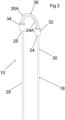
- Figures 1 to 6 show an anchor system 10 for use in securing articles to the ground.
- the anchor system 10 can be used in a support assembly 12, in which the anchor system 10 supports a post 14 which, in turn, supports a trellis, such as a vineyard trellis.
- the anchor system 10 comprises a ground anchor 16 and a tendon arrangement attached to the ground anchor 16.
- the tendon arrangement is in the form of a flexible elongate member 18 having structural properties.
- the elongate member 18 is formed of a non-metallic, non-corrosive material, such as a chemically resistant synthetic material.
- the elongate member 18 is a multifilament member, having an outer braid.
- the elongate member 18 is formed of a polymeric material, such as polyester.
- the ground anchor 16 may be one known in the art, such as disclosed in published patent application No. GB 2514004 A .
- the ground anchor 16 comprises a body 20 that enables the ground anchor 16 to be driven into the ground.
- the ground anchor 16 further includes an attaching formation comprising an apertured formation in the form of an eye 22 on the body 20.
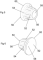
- the eye 22 defines an aperture 48.
- Protecting members in the form of first and second bushes 50 are provided in the aperture 48.
- Each of the first and second bushes 50 is received in the aperture 48 at a respective opposite side of the eye 22.
- Each of the bushes 50 comprises a substantially cylindrical main part 52, having opposite ends 54, 56.
- Each bush 52 defines a through hole 58 extending through the main part 52.
- the opposite ends 54, 56 have openings of the hole 58.
- the elongate member 18 can extend through the hole 58 of each bush 50.
- Each bush 50 has a flange 60.
- the flange 60 extends radially outwardly from the main part 52 at one of the opposite ends 54.
- the flange 60 defines a concave recess 62.
- One of the openings of the hole 58 is defined in the recess 62.
- Each bush 50 comprises mounting ribs 64 for mounting the bush 50 in the aperture 48.
- the ribs 64 deform when the bush 50 is pushed into the aperture 48 of the eye 22.
- the presence of the ribs 64 has the effect of mounting the bush 50 in the aperture 48 more securely than without such ribs.
- the ribs 64 extend along the main part 52 and across the flange 60.
- the bushes 50 are inserted into the aperture 48 in an orientation in which the end 56 is received in the aperture 48, and the flange 60 projecting therefrom.
- the elongate member 18 extends from the aperture 48 at opposite sides of the eye 22.
- the bush 23 is formed of a plastics material and has the effect of minimising wear on the elongate member 18.
- the flanges 60 of both bushes 50 protect the elongate member 18 from the corners of the aperture 48.
- the bush 23 creates a non-conductive barrier between the elongate member 18 and the ground anchor 16, thereby allowing the elongate member 18 to be formed of a metallic material, such as stainless steel, instead of a polymeric material.
- the elongate member 18 has opposite first and second ends 24, 26.
- First and second end portions 24A, 26A extend respectively from the first and second ends 24, 26.
- the elongate member 18 In use, the elongate member 18 extends through the eye 22 on the body 20. First and second passes 28, 30 of the elongate member 18 extend from the eye 22.
- the first and second passes 28, 30 are attached to each other in an overlapping configuration at the first and second end portions 24A, 26A.
- the first end 24 and the first end portion 24A are provided on the first pass 28.
- the second end 26 and the second end portion 26A are provided on the second pass 30.
- the first end 24 is arranged adjacent the second end portion 26A, and the second end 26 is arranged adjacent the first end portion 24A.
- the first end portion 24A extends from the first end 24 across the second end 26, and the second end portion 26A extends from the second end 26 across the first end 24.
- the first and second end portions 24A, 26A of the elongate member 18 are joined to each other in the overlapping configuration by a joining arrangement.
- the joining arrangement comprises first and second ferrules 32, 34.
- the joining arrangement may be other suitable clamping components.
- the first ferrule 32 is provided adjacent the first end 24 of the elongate member 18, between the first end 24 and the second ferrule 34.
- the second ferrule 34 is provided adjacent the second end 26 of the elongate member 18, between the second end 26 and the first ferrule 32.
- the joined first and second end portions 24A, 26A of the elongate member 18 form a looped region 36 of the elongate member 18.
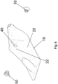
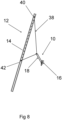
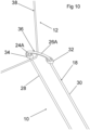
- the anchor system 10 forms part of the support assembly 12, shown in Figures 7 to 11 .
- the support assembly 12 comprises the anchor system 10, an elongate support in the form of the post 14, and an elongate tether 38.
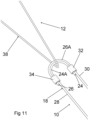
- the elongate tether 38 extends from an upper location 40 of the post 14 through the looped region 36 of the elongate member 18, and from the looped region 36 to a lower location 42 of the post 14.
- the post 14 defines a plurality of apertures along its length.
- the tether 38 extends through the apertures at the upper and lower locations 40, 42 of the post 14 and is secured to the post 14 by any means known in the art.
- the tether 38 extends through the looped region 36 of the elongate member 18, and is pulled tightly against the overlapping first and second end portions 24A, 26A at the looped region 36.
- Figures 10 and 11 show the tether 38 spaced from the looped region 36.
- the tether 38 and the looped region 36 are shown this way for clarity. In reality, the tether 38 engages the looped region 36 tightly.
- the support assembly 12 supports a trellis, such as a vineyard trellis, represented in Figure 9 by the wire 44.
- an anchor system 10 having an anchor 16 and an elongate member 18 attached to the anchor 16.
- the elongate member 18 extends in two passes 28, 30 from the elongate member 18, wherein the opposite end portions 24A, 26A of the elongate member 18 are secured to each other in an overlapping configuration.
- the load on the elongate member 18 can be twice as much as the load on a single pass.
- the elongate member 18 from a non-metallic material, corrosion of the elongate member 18 in the ground can be avoided.
- the first and second ferrules 32, 34 are also above the ground, thereby obviating the corrosive effects of the ground on the ferrules.
- a further advantage of the overlapping first and second end portions 24A, 26A in the embodiment described above is that excessive wear to any one part of the looped region 36 is prevented thereby making the anchor system 10 stronger than prior art systems.
Landscapes
- Engineering & Computer Science (AREA)
- Structural Engineering (AREA)
- Architecture (AREA)
- Civil Engineering (AREA)
- Life Sciences & Earth Sciences (AREA)
- General Life Sciences & Earth Sciences (AREA)
- Paleontology (AREA)
- General Engineering & Computer Science (AREA)
- Mining & Mineral Resources (AREA)
- Botany (AREA)
- Environmental Sciences (AREA)
- Piles And Underground Anchors (AREA)
- Joining Of Building Structures In Genera (AREA)
Claims (15)
- Ensemble support comprenant un système d'ancrage (10), un support (14) et un article de fixation (14) pour fixer le support (14) au système d'ancrage (10) ;
le système d'ancrage (10) comprenant :une ancre (16) et un agencement de tendon (18) ;l'ancre (16) ayant une formation d'attache (22) pour attacher l'agencement de tendon (18) à l'ancre (16), l'agencement de tendon (18) s'étendant à partir de la formation d'attache (22) en tant que premier et second passages (28, 30) de l'agencement de tendon (18) ;dans lequel l'agencement de tendon (18) a des première et seconde parties d'extrémité opposées (24A, 26A) ;le système comprenant en outre un agencement de liaison (32, 34) pour relier les première et seconde parties d'extrémité (24A, 26A) l'une à l'autre ;dans lequel l'agencement de tendon (18) comprend une région en boucle (36) à travers laquelle un article de fixation (14) peut s'étendre, l'agencement de tendon (18) s'étendant de la formation d'attache (22) à la région en boucle (36) ;caractérisé en ce que l'agencement de tendon (18) comprend un élément allongé (18) s'étendant à travers la formation d'attache (22) pour fournir les premier et second passages (28, 30) ; etle système d'ancrage (10) comprend un élément de protection (50) définissant un trou traversant (58), l'élément de protection (50) étant reçu à l'intérieur de la formation d'attache (22) pour recevoir l'élément allongé (18) à travers celle-ci, et l'élément allongé (18) s'étendant à travers le trou (58). - Ensemble support selon la revendication 1, dans lequel les premier et second passages (28, 30) de l'agencement de tendon (18) s'étendent le long l'un de l'autre à partir de la formation d'attache (22) jusqu'à la région en boucle (36).
- Ensemble support selon la revendication 1 ou 2, dans lequel les première et seconde parties d'extrémité jointes (24A, 26A) fournissent la région en boucle (36).
- Ensemble support selon l'une quelconque des revendications précédentes, dans lequel les premier et second passages (28, 30) de l'agencement de tendon (18) sont sensiblement de même longueur l'un par rapport à l'autre, et la région en boucle (36) étant les parties d'extrémité jointes de l'agencement de tendon (18).
- Ensemble support selon une quelconque revendication précédente, dans lequel l'agencement de liaison (32, 34) comprend des premier et second composants de serrage pour relier les première et seconde parties d'extrémité (24A, 26A) l'une à l'autre, les première et seconde parties d'extrémité (24A, 26A) étant agencées dans une configuration de chevauchement, dans laquelle les première et seconde parties d'extrémité (24A, 26A) se chevauchent l'une l'autre.
- Ensemble support selon la revendication 5, dans lequel la première partie d'extrémité (24A) s'étend à partir d'une première extrémité (24) de l'agencement de tendon (18), le premier composant de serrage étant disposé adjacent à la première extrémité (24) de l'agencement de tendon (18) ; et
dans lequel la seconde partie d'extrémité (26A) s'étend à partir d'une seconde extrémité (26) de l'agencement de tendon (18), et le second composant de serrage étant disposé adjacent à la seconde extrémité (26) de l'agencement de tendon (18). - Ensemble support selon l'une quelconque des revendications précédentes, dans lequel le premier passage (28) comprend la première partie d'extrémité (24A) de l'agencement de tendon (18), et le second passage (30) comprend la seconde partie d'extrémité (26A) de l'agencement de tendon (18), la seconde partie d'extrémité (26A) s'étendant à travers la première extrémité (24), la première partie d'extrémité (24A) s'étendant à travers la seconde extrémité (26).
- Ensemble support selon la revendication 7, dans lequel la région en boucle (36) comprend les première et seconde parties d'extrémité se chevauchant (24A, 26A), la première extrémité (24) étant agencée adjacente à la seconde partie d'extrémité (26A), et la seconde extrémité (26) étant agencée adjacente à la première partie d'extrémité (24A).
- Ensemble support selon l'une quelconque des revendications précédentes, dans lequel l'élément de protection (50) comprend une douille définissant un trou traversant (58), l'agencement de tendon (18) s'étendant à travers le trou (58), et l'élément de protection (50) est reçu à l'intérieur de la formation d'attache (22) pour recevoir l'agencement de tendon (18) à travers celle-ci.
- Ensemble support selon l'une quelconque des revendications précédentes, dans lequel l'élément de protection (50) comprend une partie principale (52) ayant des extrémités opposées (54, 56), le trou (58) s'étendant entre les extrémités opposées (54, 56).
- Ensemble support selon la revendication 10, dans lequel l'élément de protection (50) comprend une partie saillante (60) s'étendant vers l'extérieur à partir de la partie principale (52), la partie saillante (60) définissant un évidement concave (62), et le trou (58) ayant une ouverture dans l'évidement (62).
- Ensemble support selon la revendication 11, dans lequel la partie saillante (60) comprend une partie évasée.
- Ensemble support selon la revendication 11 ou 12, dans lequel la partie saillante (60) s'étend vers l'extérieur à partir d'une extrémité de la partie principale (52), l'extrémité opposée de l'élément de protection (50) étant reçue par la formation d'attache (22).
- Ensemble support selon l'une quelconque des revendications précédentes, dans lequel le support (14) est un support allongé (14), et l'article de fixation (14) comprend une amarre allongée (38).
- Ensemble support selon l'une quelconque des revendications précédentes, dans lequel l'article de fixation (14) s'étend à travers la région en boucle (36) pour fixer le support (14) au système d'ancrage (10), l'article de fixation (14) s'étendant à partir d'un emplacement supérieur (40) sur le support (14) à travers la région en boucle (36), et à partir de la région en boucle (36) jusqu'à un emplacement inférieur (42) sur le support (14), fixant ainsi le support (14) au système d'ancrage (10).
Priority Applications (1)
| Application Number | Priority Date | Filing Date | Title |
|---|---|---|---|
| EP25150745.5A EP4512232A3 (fr) | 2020-05-26 | 2021-05-13 | Système d'ancrage |
Applications Claiming Priority (3)
| Application Number | Priority Date | Filing Date | Title |
|---|---|---|---|
| GBGB2007803.6A GB202007803D0 (en) | 2020-05-26 | 2020-05-26 | Anchor system |
| GB2106411.8A GB2599757B (en) | 2020-05-26 | 2021-05-05 | Anchor system |
| PCT/IB2021/054098 WO2021240285A1 (fr) | 2020-05-26 | 2021-05-13 | Système d'ancrage |
Related Child Applications (2)
| Application Number | Title | Priority Date | Filing Date |
|---|---|---|---|
| EP25150745.5A Division EP4512232A3 (fr) | 2020-05-26 | 2021-05-13 | Système d'ancrage |
| EP25150745.5A Division-Into EP4512232A3 (fr) | 2020-05-26 | 2021-05-13 | Système d'ancrage |
Publications (3)
| Publication Number | Publication Date |
|---|---|
| EP4156901A1 EP4156901A1 (fr) | 2023-04-05 |
| EP4156901B1 true EP4156901B1 (fr) | 2025-03-05 |
| EP4156901C0 EP4156901C0 (fr) | 2025-03-05 |
Family
ID=71406434
Family Applications (2)
| Application Number | Title | Priority Date | Filing Date |
|---|---|---|---|
| EP25150745.5A Pending EP4512232A3 (fr) | 2020-05-26 | 2021-05-13 | Système d'ancrage |
| EP21727233.5A Active EP4156901B1 (fr) | 2020-05-26 | 2021-05-13 | Système d'ancrage |
Family Applications Before (1)
| Application Number | Title | Priority Date | Filing Date |
|---|---|---|---|
| EP25150745.5A Pending EP4512232A3 (fr) | 2020-05-26 | 2021-05-13 | Système d'ancrage |
Country Status (4)
| Country | Link |
|---|---|
| US (1) | US12270176B2 (fr) |
| EP (2) | EP4512232A3 (fr) |
| GB (3) | GB202007803D0 (fr) |
| WO (1) | WO2021240285A1 (fr) |
Family Cites Families (23)
| Publication number | Priority date | Publication date | Assignee | Title |
|---|---|---|---|---|
| US600401A (en) * | 1898-03-08 | Portable wire fence | ||
| US610184A (en) * | 1898-09-06 | Land-anchor for posts | ||
| US1546798A (en) * | 1924-11-28 | 1925-07-21 | Seagren Nils | Cord or rope holder |
| US2712864A (en) * | 1952-10-03 | 1955-07-12 | Jr Merton L Clevett | Ground anchor |
| US3080024A (en) * | 1958-10-16 | 1963-03-05 | Laconia Malleable Iron Company | Ground anchor |
| US3139163A (en) * | 1960-12-27 | 1964-06-30 | Augustine C Haller | Ground anchor |
| US3449874A (en) * | 1967-08-21 | 1969-06-17 | Jean L Beaupre | House anchorage |
| US3949527A (en) * | 1974-08-09 | 1976-04-13 | Canamer Leasing Services Inc. | Material supported cover and method for securing said cover to the ground |
| US4319428A (en) * | 1979-12-28 | 1982-03-16 | Fox Daniel W | Adjustable tree tie down |
| US4400114A (en) * | 1982-02-03 | 1983-08-23 | The United States Of America As Represented By The Secretary Of Agriculture | Earth anchor apparatus and method |
| US4953576A (en) * | 1989-05-02 | 1990-09-04 | Connelly Thomas R | Method and apparatus for staking articles to a ground surface |
| USD334168S (en) * | 1991-03-29 | 1993-03-23 | Eldon Baker | Boat tiller holder |
| US5461833A (en) * | 1994-08-01 | 1995-10-31 | Murray; John J. | Easy-up sand anchor |
| US6238143B1 (en) * | 1999-10-01 | 2001-05-29 | Alan Zablonski | Ground anchor |
| JP4493210B2 (ja) * | 2000-12-27 | 2010-06-30 | ポップリベット・ファスナー株式会社 | マット用固定具 |
| EP1477613A1 (fr) * | 2003-05-14 | 2004-11-17 | Philippe Cantet | Ancrage au sol avec moyens de protection du tirant et profil de pénétration concave |
| US7353833B1 (en) * | 2005-03-15 | 2008-04-08 | Nanette Palmer | Covering structure with soil anchors |
| NZ553958A (en) * | 2007-03-19 | 2008-04-30 | Miles Edward Moffat | Ground Anchor with cable guiding means for a loop of a winch cable |
| US8567018B2 (en) * | 2009-12-24 | 2013-10-29 | Jeffery Dahl | Linkable rope assembly |
| ITPN20110053A1 (it) * | 2011-07-19 | 2013-01-20 | Bortolussi Mollificio Srl | Dispositivo per controventare un palo infisso nel terreno |
| GB2514004B (en) * | 2013-04-29 | 2017-05-03 | Gripple Ltd | Ground anchor |
| KR101638149B1 (ko) * | 2016-02-16 | 2016-07-11 | 김홍관 | 금속 장식물 고정장치 |
| US20190387692A1 (en) * | 2018-06-22 | 2019-12-26 | Tropicana Products, Inc. | Netting installation for use in tree fruit production |
-
2020
- 2020-05-26 GB GBGB2007803.6A patent/GB202007803D0/en not_active Ceased
-
2021
- 2021-05-05 GB GB2106411.8A patent/GB2599757B/en active Active
- 2021-05-05 GB GB2216745.6A patent/GB2609173B/en active Active
- 2021-05-13 EP EP25150745.5A patent/EP4512232A3/fr active Pending
- 2021-05-13 US US17/924,144 patent/US12270176B2/en active Active
- 2021-05-13 WO PCT/IB2021/054098 patent/WO2021240285A1/fr not_active Ceased
- 2021-05-13 EP EP21727233.5A patent/EP4156901B1/fr active Active
Also Published As
| Publication number | Publication date |
|---|---|
| EP4512232A2 (fr) | 2025-02-26 |
| US12270176B2 (en) | 2025-04-08 |
| GB202007803D0 (en) | 2020-07-08 |
| GB2599757A (en) | 2022-04-13 |
| US20230272590A1 (en) | 2023-08-31 |
| GB2609173B (en) | 2024-06-05 |
| WO2021240285A1 (fr) | 2021-12-02 |
| GB202106411D0 (en) | 2021-06-16 |
| EP4156901C0 (fr) | 2025-03-05 |
| GB2609173A (en) | 2023-01-25 |
| EP4512232A3 (fr) | 2025-04-30 |
| GB2599757B (en) | 2023-01-04 |
| EP4156901A1 (fr) | 2023-04-05 |
| GB202216745D0 (en) | 2022-12-28 |
Similar Documents
| Publication | Publication Date | Title |
|---|---|---|
| US4619440A (en) | Fencing device, a stake, a fastener and an assembly part for such a device | |
| AU2007246159B2 (en) | Barrier improvements | |
| US11773617B2 (en) | Article and assembly for securing a line to an external surface, such as a fence post | |
| US20030066995A1 (en) | Fence post connector | |
| US6050549A (en) | Fence clip system | |
| EP3464757B1 (fr) | Système de renfort de clôture | |
| EP4156901B1 (fr) | Système d'ancrage | |
| US10850148B2 (en) | Trampoline safety enclosure | |
| AU2022203460A1 (en) | Fence Device | |
| JP6319918B1 (ja) | 害獣侵入防止ネット | |
| US10645919B2 (en) | Bird deterrent | |
| US20090057637A1 (en) | Mounting Straps for Barriers | |
| AU2018223005B2 (en) | Post attachment | |
| EP3109377A1 (fr) | Attache de barbelé pour une clôture en fil métallique | |
| EP2324701A1 (fr) | Système d'attachement | |
| GB2601188A (en) | Fencing system and clip thereof | |
| KR200329606Y1 (ko) | 낙하물 방지망 지지대 | |
| KR20100009552U (ko) | 과수나무의 가지처짐방지용 견인줄결속부를 가지는 방조망설치용 와이어고정부재 | |
| EP4473176A1 (fr) | Poteau de clôture, clôture et procédé associé | |
| JP7664637B2 (ja) | 防獣ネット用固定具 | |
| US20130092891A1 (en) | Portable delimiting device and post made of flexible material | |
| AU2004203557A1 (en) | A plastic clip and post assembly | |
| DE7148387U (de) | Schneezaun | |
| CN120959091A (zh) | 果树遮蔽棚 | |
| AU2007200643B1 (en) | A Wire Fence Clip |
Legal Events
| Date | Code | Title | Description |
|---|---|---|---|
| STAA | Information on the status of an ep patent application or granted ep patent |
Free format text: STATUS: UNKNOWN |
|
| STAA | Information on the status of an ep patent application or granted ep patent |
Free format text: STATUS: THE INTERNATIONAL PUBLICATION HAS BEEN MADE |
|
| PUAI | Public reference made under article 153(3) epc to a published international application that has entered the european phase |
Free format text: ORIGINAL CODE: 0009012 |
|
| STAA | Information on the status of an ep patent application or granted ep patent |
Free format text: STATUS: REQUEST FOR EXAMINATION WAS MADE |
|
| 17P | Request for examination filed |
Effective date: 20230203 |
|
| AK | Designated contracting states |
Kind code of ref document: A1 Designated state(s): AL AT BE BG CH CY CZ DE DK EE ES FI FR GB GR HR HU IE IS IT LI LT LU LV MC MK MT NL NO PL PT RO RS SE SI SK SM TR |
|
| DAV | Request for validation of the european patent (deleted) | ||
| DAX | Request for extension of the european patent (deleted) | ||
| GRAP | Despatch of communication of intention to grant a patent |
Free format text: ORIGINAL CODE: EPIDOSNIGR1 |
|
| STAA | Information on the status of an ep patent application or granted ep patent |
Free format text: STATUS: GRANT OF PATENT IS INTENDED |
|
| RIC1 | Information provided on ipc code assigned before grant |
Ipc: E04H 17/20 20060101ALI20241112BHEP Ipc: E04H 12/20 20060101ALI20241112BHEP Ipc: E02D 5/80 20060101ALI20241112BHEP Ipc: E04H 17/08 20060101ALI20241112BHEP Ipc: A01G 17/04 20060101AFI20241112BHEP |
|
| INTG | Intention to grant announced |
Effective date: 20241120 |
|
| GRAS | Grant fee paid |
Free format text: ORIGINAL CODE: EPIDOSNIGR3 |
|
| GRAA | (expected) grant |
Free format text: ORIGINAL CODE: 0009210 |
|
| STAA | Information on the status of an ep patent application or granted ep patent |
Free format text: STATUS: THE PATENT HAS BEEN GRANTED |
|
| RBV | Designated contracting states (corrected) |
Designated state(s): AL AT BE BG CH CY CZ DE DK EE ES FI FR GR HR HU IE IS IT LI LT LU LV MC MK MT NL NO PL PT RO RS SE SI SK SM TR |
|
| AK | Designated contracting states |
Kind code of ref document: B1 Designated state(s): AL AT BE BG CH CY CZ DE DK EE ES FI FR GR HR HU IE IS IT LI LT LU LV MC MK MT NL NO PL PT RO RS SE SI SK SM TR |
|
| REG | Reference to a national code |
Ref country code: CH Ref legal event code: EP |
|
| REG | Reference to a national code |
Ref country code: DE Ref legal event code: R096 Ref document number: 602021027151 Country of ref document: DE |
|
| REG | Reference to a national code |
Ref country code: IE Ref legal event code: FG4D |
|
| U01 | Request for unitary effect filed |
Effective date: 20250306 |
|
| U07 | Unitary effect registered |
Designated state(s): AT BE BG DE DK EE FI FR IT LT LU LV MT NL PT RO SE SI Effective date: 20250314 |
|
| U20 | Renewal fee for the european patent with unitary effect paid |
Year of fee payment: 5 Effective date: 20250519 |
|
| PG25 | Lapsed in a contracting state [announced via postgrant information from national office to epo] |
Ref country code: RS Free format text: LAPSE BECAUSE OF FAILURE TO SUBMIT A TRANSLATION OF THE DESCRIPTION OR TO PAY THE FEE WITHIN THE PRESCRIBED TIME-LIMIT Effective date: 20250605 |
|
| PG25 | Lapsed in a contracting state [announced via postgrant information from national office to epo] |
Ref country code: ES Free format text: LAPSE BECAUSE OF FAILURE TO SUBMIT A TRANSLATION OF THE DESCRIPTION OR TO PAY THE FEE WITHIN THE PRESCRIBED TIME-LIMIT Effective date: 20250305 |
|
| PG25 | Lapsed in a contracting state [announced via postgrant information from national office to epo] |
Ref country code: NO Free format text: LAPSE BECAUSE OF FAILURE TO SUBMIT A TRANSLATION OF THE DESCRIPTION OR TO PAY THE FEE WITHIN THE PRESCRIBED TIME-LIMIT Effective date: 20250605 |
|
| PG25 | Lapsed in a contracting state [announced via postgrant information from national office to epo] |
Ref country code: HR Free format text: LAPSE BECAUSE OF FAILURE TO SUBMIT A TRANSLATION OF THE DESCRIPTION OR TO PAY THE FEE WITHIN THE PRESCRIBED TIME-LIMIT Effective date: 20250305 |
|
| PG25 | Lapsed in a contracting state [announced via postgrant information from national office to epo] |
Ref country code: GR Free format text: LAPSE BECAUSE OF FAILURE TO SUBMIT A TRANSLATION OF THE DESCRIPTION OR TO PAY THE FEE WITHIN THE PRESCRIBED TIME-LIMIT Effective date: 20250606 |
|
| PG25 | Lapsed in a contracting state [announced via postgrant information from national office to epo] |
Ref country code: SM Free format text: LAPSE BECAUSE OF FAILURE TO SUBMIT A TRANSLATION OF THE DESCRIPTION OR TO PAY THE FEE WITHIN THE PRESCRIBED TIME-LIMIT Effective date: 20250305 |
|
| PG25 | Lapsed in a contracting state [announced via postgrant information from national office to epo] |
Ref country code: PL Free format text: LAPSE BECAUSE OF FAILURE TO SUBMIT A TRANSLATION OF THE DESCRIPTION OR TO PAY THE FEE WITHIN THE PRESCRIBED TIME-LIMIT Effective date: 20250305 |
|
| PG25 | Lapsed in a contracting state [announced via postgrant information from national office to epo] |
Ref country code: CZ Free format text: LAPSE BECAUSE OF FAILURE TO SUBMIT A TRANSLATION OF THE DESCRIPTION OR TO PAY THE FEE WITHIN THE PRESCRIBED TIME-LIMIT Effective date: 20250305 |
|
| PG25 | Lapsed in a contracting state [announced via postgrant information from national office to epo] |
Ref country code: SK Free format text: LAPSE BECAUSE OF FAILURE TO SUBMIT A TRANSLATION OF THE DESCRIPTION OR TO PAY THE FEE WITHIN THE PRESCRIBED TIME-LIMIT Effective date: 20250305 |
|
| PG25 | Lapsed in a contracting state [announced via postgrant information from national office to epo] |
Ref country code: IS Free format text: LAPSE BECAUSE OF FAILURE TO SUBMIT A TRANSLATION OF THE DESCRIPTION OR TO PAY THE FEE WITHIN THE PRESCRIBED TIME-LIMIT Effective date: 20250705 |