EP4512232A2 - Système d'ancrage - Google Patents
Système d'ancrage Download PDFInfo
- Publication number
- EP4512232A2 EP4512232A2 EP25150745.5A EP25150745A EP4512232A2 EP 4512232 A2 EP4512232 A2 EP 4512232A2 EP 25150745 A EP25150745 A EP 25150745A EP 4512232 A2 EP4512232 A2 EP 4512232A2
- Authority
- EP
- European Patent Office
- Prior art keywords
- anchor
- arrangement
- support assembly
- tendon arrangement
- assembly according
- Prior art date
- Legal status (The legal status is an assumption and is not a legal conclusion. Google has not performed a legal analysis and makes no representation as to the accuracy of the status listed.)
- Pending
Links
Images


Classifications
-
- E—FIXED CONSTRUCTIONS
- E02—HYDRAULIC ENGINEERING; FOUNDATIONS; SOIL SHIFTING
- E02D—FOUNDATIONS; EXCAVATIONS; EMBANKMENTS; UNDERGROUND OR UNDERWATER STRUCTURES
- E02D5/00—Bulkheads, piles, or other structural elements specially adapted to foundation engineering
- E02D5/74—Means for anchoring structural elements or bulkheads
- E02D5/80—Ground anchors
-
- A—HUMAN NECESSITIES
- A01—AGRICULTURE; FORESTRY; ANIMAL HUSBANDRY; HUNTING; TRAPPING; FISHING
- A01G—HORTICULTURE; CULTIVATION OF VEGETABLES, FLOWERS, RICE, FRUIT, VINES, HOPS OR SEAWEED; FORESTRY; WATERING
- A01G17/00—Cultivation of hops, vines, fruit trees, or like trees
- A01G17/04—Supports for hops, vines, or trees
-
- E—FIXED CONSTRUCTIONS
- E02—HYDRAULIC ENGINEERING; FOUNDATIONS; SOIL SHIFTING
- E02D—FOUNDATIONS; EXCAVATIONS; EMBANKMENTS; UNDERGROUND OR UNDERWATER STRUCTURES
- E02D5/00—Bulkheads, piles, or other structural elements specially adapted to foundation engineering
- E02D5/74—Means for anchoring structural elements or bulkheads
- E02D5/80—Ground anchors
- E02D5/803—Ground anchors with pivotable anchoring members
-
- E—FIXED CONSTRUCTIONS
- E04—BUILDING
- E04H—BUILDINGS OR LIKE STRUCTURES FOR PARTICULAR PURPOSES; SWIMMING OR SPLASH BATHS OR POOLS; MASTS; FENCING; TENTS OR CANOPIES, IN GENERAL
- E04H12/00—Towers; Masts or poles; Chimney stacks; Water-towers; Methods of erecting such structures
- E04H12/20—Side-supporting means therefor, e.g. using guy ropes or struts
-
- E—FIXED CONSTRUCTIONS
- E04—BUILDING
- E04H—BUILDINGS OR LIKE STRUCTURES FOR PARTICULAR PURPOSES; SWIMMING OR SPLASH BATHS OR POOLS; MASTS; FENCING; TENTS OR CANOPIES, IN GENERAL
- E04H17/00—Fencing, e.g. fences, enclosures, corrals
- E04H17/14—Fences constructed of rigid elements, e.g. with additional wire fillings or with posts
- E04H17/20—Posts therefor
- E04H17/23—Posts therefor lateral supporting elements, e.g. braces, tie downs, or cables
-
- D—TEXTILES; PAPER
- D07—ROPES; CABLES OTHER THAN ELECTRIC
- D07B—ROPES OR CABLES IN GENERAL
- D07B1/00—Constructional features of ropes or cables
- D07B1/18—Grommets
-
- D—TEXTILES; PAPER
- D07—ROPES; CABLES OTHER THAN ELECTRIC
- D07B—ROPES OR CABLES IN GENERAL
- D07B1/00—Constructional features of ropes or cables
- D07B1/18—Grommets
- D07B1/185—Grommets characterised by the eye construction
-
- E—FIXED CONSTRUCTIONS
- E02—HYDRAULIC ENGINEERING; FOUNDATIONS; SOIL SHIFTING
- E02D—FOUNDATIONS; EXCAVATIONS; EMBANKMENTS; UNDERGROUND OR UNDERWATER STRUCTURES
- E02D17/00—Excavations; Bordering of excavations; Making embankments
- E02D17/20—Securing of slopes or inclines
- E02D17/202—Securing of slopes or inclines with flexible securing means
-
- E—FIXED CONSTRUCTIONS
- E04—BUILDING
- E04H—BUILDINGS OR LIKE STRUCTURES FOR PARTICULAR PURPOSES; SWIMMING OR SPLASH BATHS OR POOLS; MASTS; FENCING; TENTS OR CANOPIES, IN GENERAL
- E04H17/00—Fencing, e.g. fences, enclosures, corrals
- E04H17/02—Wire fencing, e.g. made of wire mesh
- E04H17/06—Parts for wire fences
- E04H17/08—Anchoring means therefor, e.g. specially-shaped parts entering the ground; Struts or the like
Definitions
- This invention relates to anchor systems. More particularly, but not exclusively, this invention relates to anchor systems comprising ground anchors.
- ground anchors for example in the support of vineyard trellises.
- the articles are attached to the anchor by cables.
- the cables there is a tendency for the cables to corrode.
- the components of the vineyard trellis can be made from dissimilar metals which can worsen deterioration of the ground anchor and the cable.
- an anchor system comprising:
- the first and second end portions may extend along each other.
- the first and second passes of the tendon arrangement may extend from the attaching formation to the looped region.
- an anchor system comprising:
- the tendon arrangement may comprise an elongate member, which may extend through the attaching formation to provide the first and second passes.
- an anchor system comprising:
- the joined first and second end portions may provide the looped region.
- the securing article may be an elongate securing article, such as a cable, wire, or wire rope.
- the attaching formation may comprise an apertured formation.
- the anchor may have a body.
- the apertured formation may be provided on the body.
- the apertured formation may comprise an eye.
- the body may enable the anchor to be driven into the ground.
- the first and second passes of the elongate member may be substantially the same length as each other.
- the looped region may be the joined end portions of the elongate member.
- an anchor system comprising:
- a support assembly comprising an anchor system as described above, a support and a securing article to secure the support to the anchor system.
- the anchor may comprise a ground anchor.
- the anchor system may include protecting means.
- the protecting means may be mounted in the attaching formation.
- the protecting means may comprise a protecting member.
- the protecting means may comprise first and second protecting members. Each of the first and second protecting members may be received in a respective opposite side of the attaching formation.
- The, or each, protecting member may comprise a bush.
- The, or each, protecting member may define a through hole.
- The, or each, protecting member may be received within the attaching formation to receive the elongate member therethrough.
- the elongate member may extend through the hole.
- The, or each, protecting member may comprise a main part, which may be substantially cylindrical.
- the main part may have opposite ends.
- the hole may extend between the opposite ends.
- The, or each, protecting member may comprise a projecting part.
- the projecting part may extend outwardly from the main part.
- the projecting part may comprise a flared portion.
- the projecting part may comprise a flange.
- the projecting part may define a concave recess.
- the hole may have an opening in the recess.
- the projecting part may extend outwardly from one end of the main part.
- the opposite end of the, or each, protecting member may be received by the attaching formation.
- The, or each, protecting member may comprise mounting formations for mounting the protecting member in the aperture.
- the mounting formations may extend along the main part.
- the mounting formations may extend across the projecting part.
- the mounting formations may comprise ribs.
- the first pass may include the first end portion of the elongate member.
- the second pass may include the second end portion of the elongate member.
- the second end portion may extend across the first end.
- the first end portion may extend across the second end.
- the first end may be arranged adjacent the second pass.
- the second end may be arranged adjacent the first pass.
- the first pass may extend across the second end.
- the second pass may extend across the first end.
- the looped region may comprise the overlapping first and second end portions.
- the first end may be arranged adjacent the second end portion.
- the second end may be arranged adjacent the first end portion.
- the first and second joining components may comprise respective first and second clamping components.
- the first and second joining components may comprise respective first and second ferrules.
- the elongate member may be formed of a non-corrosive material, which may be chemically resistant.
- the elongate member may be formed of a non-metallic material.
- the elongate member may be formed of a synthetic material.
- the elongate member may be formed of polymeric material, such as polyester.
- the elongate member may be formed of a metallic material, such as stainless steel.
- the elongate member may be a flexible elongate member.
- the elongate member may be a multifilament member, which may have an outer braid.
- the elongate member may have structural properties.
- the support may be an elongate support, such as a post.
- the securing article may comprise an elongate tether.
- the elongate tether may be flexible.
- the securing article may extend through the looped region to secure the support to the anchor system.
- the securing article may extend from a first location on the support through the looped region, and from the looped region to a second location on the support, thereby securing the support to the anchor system.
- the first location may be an upper location of the support.
- the second location may be a lower location of the support.
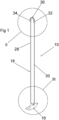
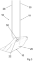
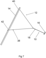
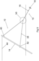
- Figures 1 to 6 show an anchor system 10 for use in securing articles to the ground.
- the anchor system 10 can be used in a support assembly 12, in which the anchor system 10 supports a post 14 which, in turn, supports a trellis, such as a vineyard trellis.
- the anchor system 10 comprises a ground anchor 16 and a tendon arrangement attached to the ground anchor 16.
- the tendon arrangement is in the form of a flexible elongate member 18 having structural properties.
- the elongate member 18 is formed of a non-metallic, non-corrosive material, such as a chemically resistant synthetic material.
- the elongate member 18 is a multifilament member, having an outer braid.
- the elongate member 18 is formed of a polymeric material, such as polyester.
- the ground anchor 16 may be one known in the art, such as disclosed in published patent application No. GB 2514004 A .
- the ground anchor 16 comprises a body 20 that enables the ground anchor 16 to be driven into the ground.
- the ground anchor 16 further includes an attaching formation comprising an apertured formation in the form of an eye 22 on the body 20.
- the eye 22 defines an aperture 48.
- Protecting members in the form of first and second bushes 50 are provided in the aperture 48.
- Each of the first and second bushes 50 is received in the aperture 48 at a respective opposite side of the eye 22.
- Each of the bushes 50 comprises a substantially cylindrical main part 52, having opposite ends 54, 56.
- Each bush 52 defines a through hole 58 extending through the main part 52.
- the opposite ends 54, 56 have openings of the hole 58.
- the elongate member 18 can extend through the hole 58 of each bush 50.
- Each bush 50 has a flange 60.
- the flange 60 extends radially outwardly from the main part 52 at one of the opposite ends 54.
- the flange 60 defines a concave recess 62.
- One of the openings of the hole 58 is defined in the recess 62.
- Each bush 50 comprises mounting ribs 64 for mounting the bush 50 in the aperture 48.
- the ribs 64 deform when the bush 50 is pushed into the aperture 48 of the eye 22.
- the presence of the ribs 64 has the effect of mounting the bush 50 in the aperture 48 more securely than without such ribs.
- the ribs 64 extend along the main part 52 and across the flange 60.
- the bushes 50 are inserted into the aperture 48 in an orientation in which the end 56 is received in the aperture 48, and the flange 60 projecting therefrom.
- the elongate member 18 extends from the aperture 48 at opposite sides of the eye 22.
- the bush 23 is formed of a plastics material and has the effect of minimising wear on the elongate member 18.
- the flanges 60 of both bushes 50 protect the elongate member 18 from the corners of the aperture 48.
- the bush 23 creates a non-conductive barrier between the elongate member 18 and the ground anchor 16, thereby allowing the elongate member 18 to be formed of a metallic material, such as stainless steel, instead of a polymeric material.
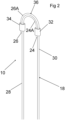
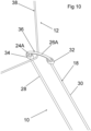
- the elongate member 18 has opposite first and second ends 24, 26.
- First and second end portions 24A, 26A extend respectively from the first and second ends 24, 26.
- the elongate member 18 In use, the elongate member 18 extends through the eye 22 on the body 20. First and second passes 28, 30 of the elongate member 18 extend from the eye 22.
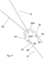
- the first and second passes 28, 30 are attached to each other in an overlapping configuration at the first and second end portions 24A, 26A.
- the first end 24 and the first end portion 24A are provided on the first pass 28.
- the second end 26 and the second end portion 26A are provided on the second pass 30.
- the first end 24 is arranged adjacent the second end portion 26A, and the second end 26 is arranged adjacent the first end portion 24A.
- the first end portion 24A extends from the first end 24 across the second end 26, and the second end portion 26A extends from the second end 26 across the first end 24.
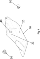
- the first and second end portions 24A, 26A of the elongate member 18 are joined to each other in the overlapping configuration by a joining arrangement.
- the joining arrangement comprises first and second ferrules 32, 34.
- the joining arrangement may be other suitable clamping components.
- Figures 10 and 11 show the tether 38 spaced from the looped region 36.
- the tether 38 and the looped region 36 are shown this way for clarity. In reality, the tether 38 engages the looped region 36 tightly.
Landscapes
- Engineering & Computer Science (AREA)
- Structural Engineering (AREA)
- Architecture (AREA)
- Civil Engineering (AREA)
- Life Sciences & Earth Sciences (AREA)
- General Life Sciences & Earth Sciences (AREA)
- Paleontology (AREA)
- General Engineering & Computer Science (AREA)
- Mining & Mineral Resources (AREA)
- Botany (AREA)
- Environmental Sciences (AREA)
- Piles And Underground Anchors (AREA)
- Joining Of Building Structures In Genera (AREA)
Applications Claiming Priority (4)
| Application Number | Priority Date | Filing Date | Title |
|---|---|---|---|
| GBGB2007803.6A GB202007803D0 (en) | 2020-05-26 | 2020-05-26 | Anchor system |
| GB2106411.8A GB2599757B (en) | 2020-05-26 | 2021-05-05 | Anchor system |
| EP21727233.5A EP4156901B1 (fr) | 2020-05-26 | 2021-05-13 | Système d'ancrage |
| PCT/IB2021/054098 WO2021240285A1 (fr) | 2020-05-26 | 2021-05-13 | Système d'ancrage |
Related Parent Applications (2)
| Application Number | Title | Priority Date | Filing Date |
|---|---|---|---|
| EP21727233.5A Division EP4156901B1 (fr) | 2020-05-26 | 2021-05-13 | Système d'ancrage |
| EP21727233.5A Division-Into EP4156901B1 (fr) | 2020-05-26 | 2021-05-13 | Système d'ancrage |
Publications (2)
| Publication Number | Publication Date |
|---|---|
| EP4512232A2 true EP4512232A2 (fr) | 2025-02-26 |
| EP4512232A3 EP4512232A3 (fr) | 2025-04-30 |
Family
ID=71406434
Family Applications (2)
| Application Number | Title | Priority Date | Filing Date |
|---|---|---|---|
| EP25150745.5A Pending EP4512232A3 (fr) | 2020-05-26 | 2021-05-13 | Système d'ancrage |
| EP21727233.5A Active EP4156901B1 (fr) | 2020-05-26 | 2021-05-13 | Système d'ancrage |
Family Applications After (1)
| Application Number | Title | Priority Date | Filing Date |
|---|---|---|---|
| EP21727233.5A Active EP4156901B1 (fr) | 2020-05-26 | 2021-05-13 | Système d'ancrage |
Country Status (4)
| Country | Link |
|---|---|
| US (1) | US12270176B2 (fr) |
| EP (2) | EP4512232A3 (fr) |
| GB (3) | GB202007803D0 (fr) |
| WO (1) | WO2021240285A1 (fr) |
Family Cites Families (23)
| Publication number | Priority date | Publication date | Assignee | Title |
|---|---|---|---|---|
| US600401A (en) * | 1898-03-08 | Portable wire fence | ||
| US610184A (en) * | 1898-09-06 | Land-anchor for posts | ||
| US1546798A (en) * | 1924-11-28 | 1925-07-21 | Seagren Nils | Cord or rope holder |
| US2712864A (en) * | 1952-10-03 | 1955-07-12 | Jr Merton L Clevett | Ground anchor |
| US3080024A (en) * | 1958-10-16 | 1963-03-05 | Laconia Malleable Iron Company | Ground anchor |
| US3139163A (en) * | 1960-12-27 | 1964-06-30 | Augustine C Haller | Ground anchor |
| US3449874A (en) * | 1967-08-21 | 1969-06-17 | Jean L Beaupre | House anchorage |
| US3949527A (en) * | 1974-08-09 | 1976-04-13 | Canamer Leasing Services Inc. | Material supported cover and method for securing said cover to the ground |
| US4319428A (en) * | 1979-12-28 | 1982-03-16 | Fox Daniel W | Adjustable tree tie down |
| US4400114A (en) * | 1982-02-03 | 1983-08-23 | The United States Of America As Represented By The Secretary Of Agriculture | Earth anchor apparatus and method |
| US4953576A (en) * | 1989-05-02 | 1990-09-04 | Connelly Thomas R | Method and apparatus for staking articles to a ground surface |
| USD334168S (en) * | 1991-03-29 | 1993-03-23 | Eldon Baker | Boat tiller holder |
| US5461833A (en) * | 1994-08-01 | 1995-10-31 | Murray; John J. | Easy-up sand anchor |
| US6238143B1 (en) * | 1999-10-01 | 2001-05-29 | Alan Zablonski | Ground anchor |
| JP4493210B2 (ja) * | 2000-12-27 | 2010-06-30 | ポップリベット・ファスナー株式会社 | マット用固定具 |
| EP1477613A1 (fr) * | 2003-05-14 | 2004-11-17 | Philippe Cantet | Ancrage au sol avec moyens de protection du tirant et profil de pénétration concave |
| US7353833B1 (en) * | 2005-03-15 | 2008-04-08 | Nanette Palmer | Covering structure with soil anchors |
| NZ553958A (en) * | 2007-03-19 | 2008-04-30 | Miles Edward Moffat | Ground Anchor with cable guiding means for a loop of a winch cable |
| US8567018B2 (en) * | 2009-12-24 | 2013-10-29 | Jeffery Dahl | Linkable rope assembly |
| ITPN20110053A1 (it) * | 2011-07-19 | 2013-01-20 | Bortolussi Mollificio Srl | Dispositivo per controventare un palo infisso nel terreno |
| GB2514004B (en) * | 2013-04-29 | 2017-05-03 | Gripple Ltd | Ground anchor |
| KR101638149B1 (ko) * | 2016-02-16 | 2016-07-11 | 김홍관 | 금속 장식물 고정장치 |
| US20190387692A1 (en) * | 2018-06-22 | 2019-12-26 | Tropicana Products, Inc. | Netting installation for use in tree fruit production |
-
2020
- 2020-05-26 GB GBGB2007803.6A patent/GB202007803D0/en not_active Ceased
-
2021
- 2021-05-05 GB GB2106411.8A patent/GB2599757B/en active Active
- 2021-05-05 GB GB2216745.6A patent/GB2609173B/en active Active
- 2021-05-13 EP EP25150745.5A patent/EP4512232A3/fr active Pending
- 2021-05-13 US US17/924,144 patent/US12270176B2/en active Active
- 2021-05-13 WO PCT/IB2021/054098 patent/WO2021240285A1/fr not_active Ceased
- 2021-05-13 EP EP21727233.5A patent/EP4156901B1/fr active Active
Also Published As
| Publication number | Publication date |
|---|---|
| US12270176B2 (en) | 2025-04-08 |
| GB202007803D0 (en) | 2020-07-08 |
| GB2599757A (en) | 2022-04-13 |
| US20230272590A1 (en) | 2023-08-31 |
| EP4156901B1 (fr) | 2025-03-05 |
| GB2609173B (en) | 2024-06-05 |
| WO2021240285A1 (fr) | 2021-12-02 |
| GB202106411D0 (en) | 2021-06-16 |
| EP4156901C0 (fr) | 2025-03-05 |
| GB2609173A (en) | 2023-01-25 |
| EP4512232A3 (fr) | 2025-04-30 |
| GB2599757B (en) | 2023-01-04 |
| EP4156901A1 (fr) | 2023-04-05 |
| GB202216745D0 (en) | 2022-12-28 |
Similar Documents
| Publication | Publication Date | Title |
|---|---|---|
| US5518333A (en) | Studded T-post connector | |
| US9046197B2 (en) | Para-seismic support for pipes | |
| US20050242247A1 (en) | Fir tree mount for cable ties | |
| US12188252B2 (en) | Method for securing a line to an external surface, such as a fence post | |
| US4619440A (en) | Fencing device, a stake, a fastener and an assembly part for such a device | |
| AU2013204291B2 (en) | A post mounting system and apparatus | |
| EP3682150B1 (fr) | Structure soutien de tuyau | |
| AU2003281885B2 (en) | Para-seismic support for pipes | |
| EP0633973B1 (fr) | Element de fixation con u pour fixer un objet tel qu'un filet, un fil metallique, un cable ou un element similaire a un support tel qu'un poteau | |
| US20100012910A1 (en) | Barrier Improvements | |
| US5098051A (en) | Flexible banding and instrument support system | |
| US12270176B2 (en) | Anchor system | |
| US4759521A (en) | Flexible banding and instrument support system | |
| US20170130873A1 (en) | Clamping arrangement | |
| JP6251837B1 (ja) | ケーブル支持具 | |
| JP2018082624A (ja) | 害獣侵入防止ネット | |
| GB2271806A (en) | Clip member for use with I-shaped fence posts | |
| US4635888A (en) | Flexible banding and instrument support system | |
| US9068672B2 (en) | T-style grommet attachment system and method | |
| FI12707Y1 (fi) | Vaarnalenkki | |
| AU2013204419A1 (en) | Indented tendons, processes of forming and uses thereof | |
| JP7624865B2 (ja) | 落石予防構造体 | |
| CN209860556U (zh) | 泵站电缆悬挂系统及泵站系统 | |
| EP3109377A1 (fr) | Attache de barbelé pour une clôture en fil métallique | |
| EP3403501A1 (fr) | Dispositif pour repousser les animaux |
Legal Events
| Date | Code | Title | Description |
|---|---|---|---|
| PUAI | Public reference made under article 153(3) epc to a published international application that has entered the european phase |
Free format text: ORIGINAL CODE: 0009012 |
|
| STAA | Information on the status of an ep patent application or granted ep patent |
Free format text: STATUS: REQUEST FOR EXAMINATION WAS MADE |
|
| 17P | Request for examination filed |
Effective date: 20250108 |
|
| AC | Divisional application: reference to earlier application |
Ref document number: 4156901 Country of ref document: EP Kind code of ref document: P |
|
| AK | Designated contracting states |
Kind code of ref document: A2 Designated state(s): AL AT BE BG CH CY CZ DE DK EE ES FI FR GB GR HR HU IE IS IT LI LT LU LV MC MK MT NL NO PL PT RO RS SE SI SK SM TR |
|
| PUAL | Search report despatched |
Free format text: ORIGINAL CODE: 0009013 |
|
| STAA | Information on the status of an ep patent application or granted ep patent |
Free format text: STATUS: EXAMINATION IS IN PROGRESS |
|
| AK | Designated contracting states |
Kind code of ref document: A3 Designated state(s): AL AT BE BG CH CY CZ DE DK EE ES FI FR GB GR HR HU IE IS IT LI LT LU LV MC MK MT NL NO PL PT RO RS SE SI SK SM TR |
|
| RIC1 | Information provided on ipc code assigned before grant |
Ipc: E04H 17/20 20060101ALI20250324BHEP Ipc: E04H 17/08 20060101ALI20250324BHEP Ipc: E04H 12/20 20060101ALI20250324BHEP Ipc: E02D 5/80 20060101ALI20250324BHEP Ipc: A01G 17/04 20060101AFI20250324BHEP |
|
| 17Q | First examination report despatched |
Effective date: 20250409 |