EP4156432A2 - Stromversorgungssteuerungssystem und fahrzeug - Google Patents
Stromversorgungssteuerungssystem und fahrzeug Download PDFInfo
- Publication number
- EP4156432A2 EP4156432A2 EP22209129.0A EP22209129A EP4156432A2 EP 4156432 A2 EP4156432 A2 EP 4156432A2 EP 22209129 A EP22209129 A EP 22209129A EP 4156432 A2 EP4156432 A2 EP 4156432A2
- Authority
- EP
- European Patent Office
- Prior art keywords
- voltage
- power supply
- information
- supplying
- module
- Prior art date
- Legal status (The legal status is an assumption and is not a legal conclusion. Google has not performed a legal analysis and makes no representation as to the accuracy of the status listed.)
- Withdrawn
Links
Images
Classifications
-
- B—PERFORMING OPERATIONS; TRANSPORTING
- B60—VEHICLES IN GENERAL
- B60R—VEHICLES, VEHICLE FITTINGS, OR VEHICLE PARTS, NOT OTHERWISE PROVIDED FOR
- B60R16/00—Electric or fluid circuits specially adapted for vehicles and not otherwise provided for; Arrangement of elements of electric or fluid circuits specially adapted for vehicles and not otherwise provided for
- B60R16/02—Electric or fluid circuits specially adapted for vehicles and not otherwise provided for; Arrangement of elements of electric or fluid circuits specially adapted for vehicles and not otherwise provided for electric constitutive elements
- B60R16/03—Electric or fluid circuits specially adapted for vehicles and not otherwise provided for; Arrangement of elements of electric or fluid circuits specially adapted for vehicles and not otherwise provided for electric constitutive elements for supply of electrical power to vehicle subsystems or for
-
- H—ELECTRICITY
- H02—GENERATION; CONVERSION OR DISTRIBUTION OF ELECTRIC POWER
- H02J—ELECTRIC POWER NETWORKS; CIRCUIT ARRANGEMENTS OR SYSTEMS FOR SUPPLYING OR DISTRIBUTING ELECTRIC POWER; SYSTEMS FOR STORING ELECTRIC ENERGY
- H02J1/00—Circuit arrangements for DC mains or DC distribution networks
- H02J1/08—Three-wire DC power distribution systems; Systems having more than three wires
- H02J1/082—DC supplies with two or more different DC voltage levels
-
- B—PERFORMING OPERATIONS; TRANSPORTING
- B60—VEHICLES IN GENERAL
- B60R—VEHICLES, VEHICLE FITTINGS, OR VEHICLE PARTS, NOT OTHERWISE PROVIDED FOR
- B60R16/00—Electric or fluid circuits specially adapted for vehicles and not otherwise provided for; Arrangement of elements of electric or fluid circuits specially adapted for vehicles and not otherwise provided for
- B60R16/02—Electric or fluid circuits specially adapted for vehicles and not otherwise provided for; Arrangement of elements of electric or fluid circuits specially adapted for vehicles and not otherwise provided for electric constitutive elements
- B60R16/023—Electric or fluid circuits specially adapted for vehicles and not otherwise provided for; Arrangement of elements of electric or fluid circuits specially adapted for vehicles and not otherwise provided for electric constitutive elements for transmission of signals between vehicle parts or subsystems
- B60R16/0231—Circuits relating to the driving or the functioning of the vehicle
-
- H—ELECTRICITY
- H02—GENERATION; CONVERSION OR DISTRIBUTION OF ELECTRIC POWER
- H02H—EMERGENCY PROTECTIVE CIRCUIT ARRANGEMENTS
- H02H5/00—Emergency protective circuit arrangements for automatic disconnection directly responsive to an undesired change from normal non-electric working conditions with or without subsequent reconnection
- H02H5/04—Emergency protective circuit arrangements for automatic disconnection directly responsive to an undesired change from normal non-electric working conditions with or without subsequent reconnection responsive to abnormal temperature
-
- H—ELECTRICITY
- H02—GENERATION; CONVERSION OR DISTRIBUTION OF ELECTRIC POWER
- H02H—EMERGENCY PROTECTIVE CIRCUIT ARRANGEMENTS
- H02H7/00—Emergency protective circuit arrangements specially adapted for specific types of electric machines or apparatus or for sectionalised protection of cable or line systems, and effecting automatic switching in the event of an undesired change from normal working conditions
- H02H7/10—Emergency protective circuit arrangements specially adapted for specific types of electric machines or apparatus or for sectionalised protection of cable or line systems, and effecting automatic switching in the event of an undesired change from normal working conditions for converters; for rectifiers
- H02H7/12—Emergency protective circuit arrangements specially adapted for specific types of electric machines or apparatus or for sectionalised protection of cable or line systems, and effecting automatic switching in the event of an undesired change from normal working conditions for converters; for rectifiers for static converters or rectifiers
-
- H—ELECTRICITY
- H02—GENERATION; CONVERSION OR DISTRIBUTION OF ELECTRIC POWER
- H02H—EMERGENCY PROTECTIVE CIRCUIT ARRANGEMENTS
- H02H7/00—Emergency protective circuit arrangements specially adapted for specific types of electric machines or apparatus or for sectionalised protection of cable or line systems, and effecting automatic switching in the event of an undesired change from normal working conditions
- H02H7/10—Emergency protective circuit arrangements specially adapted for specific types of electric machines or apparatus or for sectionalised protection of cable or line systems, and effecting automatic switching in the event of an undesired change from normal working conditions for converters; for rectifiers
- H02H7/12—Emergency protective circuit arrangements specially adapted for specific types of electric machines or apparatus or for sectionalised protection of cable or line systems, and effecting automatic switching in the event of an undesired change from normal working conditions for converters; for rectifiers for static converters or rectifiers
- H02H7/1213—Emergency protective circuit arrangements specially adapted for specific types of electric machines or apparatus or for sectionalised protection of cable or line systems, and effecting automatic switching in the event of an undesired change from normal working conditions for converters; for rectifiers for static converters or rectifiers for DC-DC converters
-
- H—ELECTRICITY
- H02—GENERATION; CONVERSION OR DISTRIBUTION OF ELECTRIC POWER
- H02J—ELECTRIC POWER NETWORKS; CIRCUIT ARRANGEMENTS OR SYSTEMS FOR SUPPLYING OR DISTRIBUTING ELECTRIC POWER; SYSTEMS FOR STORING ELECTRIC ENERGY
- H02J13/00—Circuit arrangements for providing remote monitoring or remote control of equipment in a power distribution network
- H02J13/13—Circuit arrangements for providing remote monitoring or remote control of equipment in a power distribution network characterised by the transmission of data to equipment in the power network
- H02J13/1337—Circuit arrangements for providing remote monitoring or remote control of equipment in a power distribution network characterised by the transmission of data to equipment in the power network involving the use of Internet protocols
-
- H—ELECTRICITY
- H04—ELECTRIC COMMUNICATION TECHNIQUE
- H04L—TRANSMISSION OF DIGITAL INFORMATION, e.g. TELEGRAPHIC COMMUNICATION
- H04L12/00—Data switching networks
- H04L12/28—Data switching networks characterised by path configuration, e.g. LAN [Local Area Networks] or WAN [Wide Area Networks]
- H04L12/46—Interconnection of networks
Definitions
- the invention relates to the field of a vehicle technology, in particular to a power supply control system and a vehicle.
- An on-board power supply system in the related art realizes output control for a power supply through simple electrical components such as a relay, a conducting strip and a fuse, and a voltage platform may only realize electric signal output with a single level, but cannot satisfy power demands of various devices on a vehicle.
- the invention provides a power supply control system and a vehicle.
- a power supply control system includes:
- the voltage conversion module is configured to output a plurality of types of preset voltages, and each of the preset voltages corresponds to at least one supplying branch.
- each supplying branch is provided with a field effect transistor (FET), and the control signal is configured to control on or off of the field effect transistor.
- FET field effect transistor
- the load information includes voltage information
- the information acquisition module includes a plurality of voltage sensors provided on the supplying branches, each voltage sensor is configured to acquire voltage information of the corresponding supplying branch.
- the load information includes current information
- the information acquisition module includes a plurality of current sensors provided on the supplying branches, each current sensor is configured to acquire current information of the corresponding supplying branch.
- the power control system further includes: an electric quantity sensor provided on the low-voltage DC power supply, configured to acquire state of charge (SOC) information of the low-voltage DC power supply, in which the control module is further configured to generate a power supply state signal based on the SOC information, and the power supply state signal is configured to represent a power supply state of the low-voltage DC power supply.
- SOC state of charge
- the power control system further includes: a communication module, communicatively connected with the control module, configured to communicatively connect with a vehicle controller.
- control module is further configured to receive a vehicle signal from the vehicle controller via the communication module, and generate the control signals based on the vehicle signal.
- control module is further configured to send the temperature information of the preset area and/or the load information to the vehicle controller via the communication module.
- the communication module is configured with at least one of a Controller Area Network (CAN) communication protocol, a Local Interconnect Network (LIN) communication protocol and an Ethernet communication protocol.
- CAN Controller Area Network
- LIN Local Interconnect Network
- Ethernet Ethernet
- a vehicle includes:
- the voltage of low-voltage DC output by the low-voltage DC power supply is converted to the at least one preset voltage, and the at least one preset voltage may output through the plurality of supplying branches, thus achieving low-voltage DC output with multi voltage levels, which may satisfy electricity demands of different electrical devices.
- control module may control connection or disconnection of the supplying branches based on the temperature information of the preset area and/or the load information acquired by the information acquisition module, therefore, monitoring the temperature of the preset area and/or the load may be realized, and the output of the corresponding supplying branch is disenabled once abnormal temperature of the preset area and/or abnormal load is detected, thereby improving safety and stability of power supplying for the power supply control system.
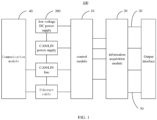
- FIG. 1 is a schematic diagram of a power supply control system according to an embodiment of the present invention.
- the power supply control system 100 according to an embodiment of the invention is described below with reference to FIG. 1 .
- the power supply control system 100 includes a plurality of supplying branches 30, a voltage conversion module, an information acquisition module 20, and a control module 10.
- the voltage conversion module is connected between an output end of the low-voltage DC power supply 200 and an input end of each of the supplying branches 30.
- the voltage conversion module is configured to convert a DC voltage output by the low-voltage DC power supply 200 to at least one preset voltage.
- the information acquisition module 20 is configured to acquire temperature information of a preset area and/or load information.
- the control module 10 communicates with the information acquisition module 20, and is configured to generate control signals for the supplying branches 30 based on the temperature information of the preset area and/or the load information.
- the power supply control system 100 of an embodiment of the invention may be applied for a vehicle, especially an autonomic vehicle.
- the power supply control system 100 may be integrated into an electrical box.
- the electrical box is suitable for being installed on the vehicle and electrically connected to the low-voltage DC power supply 200 of the vehicle.
- the electrical box is provided with a plurality of output interfaces electrically connected to the plurality of supplying branches 30, which is configured to electrically connect with electrical devices on the vehicle to supply power to the electrical devices.
- the voltage conversion module may be a DC transformer, such as, a DC-DC converter.
- the preset voltage may be set at will according to an actual situation.
- the preset voltage may be 3V, 5V, 24V or 36V.
- the voltage conversion module may convert the voltage of the low-voltage DC power supply 200 into a plurality of types of voltages, and transmit the voltages output by the voltage conversion module to respective supplying branches 30, to realize electric signal output with multi voltage levels.
- An output end of each of the supplying branches 30 is connected to the output interface of the electrical box.
- control module 10 may adopt a Microcontroller Unit (MCU).
- MCU Microcontroller Unit
- the MCU also known as single chip microcomputer or single chip machine, is a chip-level computer formed by reducing frequency and specification of a Central Process Unit (CPU), and integrating peripheral interfaces such as a memory and a timer, and even a Liquid Crystal Display (LCD) driver circuit on a single chip, and performs different combination controls for different application scenarios.
- CPU Central Process Unit
- LCD Liquid Crystal Display
- the information acquisition module 20 may include a variety of types of sensors, for example, temperature sensors, voltage sensors and current sensors, to acquire temperature information of the preset area, voltage information and current information.
- the preset area may be set according to an actual situation.
- the preset area may be an area with high power, such as a chip area for the control module 10, or an area corresponding to a supplying branch 30 with a relatively large output current.
- the control module 10 generates the control signals based on the temperature information of the preset area and/or the load information sent by the information acquisition module 20, to control connection or disconnection of the supplying branches 30.
- the control signals may include connection control signals and disconnection control signals.
- a connection control signal is configured to connect the corresponding supplying branch 30, and a disconnection control signal is configured to disconnect the corresponding power-supply branch 30.
- control module 10 when a temperature of an area corresponding to the preset area, e.g., a certain supplying branch 30, exceeds a preset temperature threshold value, the control module 10 generates and sends the disconnection control signal to disconnect the supplying branch 30 corresponding to the area.
- the voltage of the low-voltage DC output by the low-voltage DC power supply 200 is converted to the at least one preset voltage, and the at least one preset voltage may output through the plurality of supplying branches 30, thus achieving low-voltage DC output with multi voltage levels , which may satisfy electricity demands of different electrical devices.
- control module may control the connection or disconnection of the supplying branches based on the temperature information of the preset area and/or the load information acquired by the information acquisition module, therefore monitoring the temperature of the preset area and/or the load may be realized, and the output of the corresponding supplying branch 30 is disenabled once abnormal temperature of the preset area and/or abnormal load is detected, thereby improving safety and stability of power supplying for the power supply control system 100.
- each of the preset voltages corresponds to at least one supplying branches 30.
- a plurality of' refers to two or more, that is, there are at least two types of preset voltage.
- the low-voltage conversion module may adopt a DC-DC converter.
- the DC-DC converter may convert a voltage of input low-voltage DC into various types of preset voltages, and send each preset voltage to the corresponding supplying branch 30.
- the low-voltage DC power supply on the vehicle generally outputs 12V low-voltage DC.
- the voltage conversion module between the output end of the low-voltage DC power supply 200 and the supplying branches 30, may convert the voltage of the low-voltage DC from 12V to various types of preset voltage, to satisfy electricity demands of different electrical devices on the vehicle.
- the voltage conversion module may convert the voltage of the low-voltage DC into one or more preset voltages, and send each preset voltage to the corresponding supplying branch 30.
- the system may have six supplying branches 30, and the voltage conversion module may convert the voltage of the low voltage DC into 3V, 5V, 24V and 36V, respectively, an DC voltage output through a first supplying branch 30 is 3V, DC voltages output through a second supplying branch 30 and a third supplying branch 30 are 5V, DC voltages output through a fourth supplying branch 30 and a fifth supplying branch 30 are 24V and a DC voltage output through a sixth supplying branch 30 is 36V.
- the voltage of the low-voltage DC output by the low-voltage DC power supply 200 is converted into various types of preset voltages and output each preset voltage through the corresponding supplying branch 30, realizing multi-level voltage output of the power supply control system 100, which may satisfy electricity demands of different electrical devices on the vehicle with different input voltage specifications.
- each supplying branch 30 is provided with a field effect transistor (FET) such as a Metal-Oxide-Semiconductor field effect transistor (MOSFET), and the control signals are configured to control on or off of the field effect transistor.
- FET field effect transistor
- MOSFET Metal-Oxide-Semiconductor field effect transistor
- the MOSFET i.e., MOS transistor
- NMOS N-type Metal-Oxide-Semiconductor
- PMOS P-type Metal-Oxide-Semiconductor
- the MOS transistor is regarded as a switching component which may operate in two states, i.e., an on state and an off state. Since the MOS transistor is a voltage controlled element, an operating state of the MOS transistor is mainly determined by a gate-source voltage uGS. When the gate-source voltage uGS is less than a threshold voltage UT, the MOS transistor operates in a cutoff region, a drain-source current iDS is basically 0, an output voltage of the MOS transistor uDS ⁇ UDD, and the MOS transistor is in an "off' state, at this time the corresponding supplying branch 30 is in a disconnection state.
- the control signal may be an electrical signal.
- the control signal includes a connection control signal or a disconnection control signal.
- the connection control signal is configured to transmit an electrical signal with a voltage greater than the voltage UT of the MOS transistor to a gate of the MOS transistor
- the disconnection control signal is configured to transmit an electrical signal with a voltage less than the voltage UT of the MOS transistor to the gate of the MOS transistor.
- a current carrying capacity of the MOSFET on each of the supplying branches 30 may be set according to current demands of the low-voltage DC actually output by the supplying branches 30, to satisfy the corresponding electricity demands of the electrical devices. It is understood that, by limiting the current carrying capacity of the MOSFET correspondingly, the output of the supplying branches 30 may be from small current at milliampere (mA) level to large current at hundred ampere (100amp) level, to satisfy the current demands of the electrical devices.
- mA milliampere
- control module 10 may send the control signals to the MOSFETs on the supplying branches 30, to control the connection and disconnection of respective supplying branches.
- the solution of the invention may effectively reduce thermal effect when the supplying branches 30 is connected due to small on-resistance of the MOSFET.
- the load information may include voltage information
- the information acquisition module 20 includes a plurality of voltage sensors provided on the supplying branches 30, each voltage sensor is configured to acquire voltage information of the corresponding supplying branch 30.
- control module 10 compares the voltage information with a preset voltage threshold value range based on the acquired voltage information of each of the supplying branches 30. In response to the voltage information not meeting the preset voltage threshold value range, the control module 10 sends the disconnection control signal to the corresponding supplying branch 30, to disconnect the output of the supplying branch.
- the voltage threshold value range may be set according to an actual situation.
- the invention may realize monitoring the voltage of each of the supplying branches 30, and determine whether the supplying branch 30 has occurred abnormal faults such as overvoltage, undervoltage and overload according to the acquired voltage information.
- the output of the supplying branch 30 may be automatically disconnected when the voltage information is abnormal, which may improve safety performance of the power supply control system 100.
- the load information may include current information
- the information acquisition module 20 includes a plurality of current sensors provided on the supplying branches 30, each current sensor is configured to acquire current information of the corresponding supplying branch 30.
- control module 10 compares the current information with a preset current threshold value range based on the acquired current information of each of the supplying branches 30. When the current information does not meet the preset current threshold value range, the control module 10 may send the disconnection control signal to the supplying branch 30 to disconnect the output of the supplying branch.
- the current threshold value range may be set according to an actual situation.
- to the invention may realize monitoring the current of each of the supplying branches 30, and determine whether the output current of the supplying branch 30 is abnormal according to the acquired current information.
- the output of the supplying branch 30 may be automatically disconnected when the current information is abnormal, thereby improving the safety performance of the power supply control system 100.
- the information acquisition module 20 may further include a temperature sensor.
- the temperature sensor is arranged in the preset area to acquire temperature information of the preset area, and the control module 10 controls the connection and disconnection of the supplying branch 30 according to the acquired temperature information.
- the preset area may be a certain supplying branch 30 with a larger output current.
- to the invention may realize monitoring the temperature of the supplying branch 30 with a larger output current in real time, and when the temperature information does not meet a preset temperature threshold value range, the disconnection control signal is sent to the supplying branch 30, to disconnect the output of the supplying branch 30 in real time.
- the power supply control system 100 may further include an electric quantity sensor provided on the low-voltage DC power supply 200 and configured to acquire state of charge (SOC) information of the low-voltage DC power supply 200.
- the control module 10 is further configured to generate a power supply state signal according to the SOC information, and the power supply state signal is configured to represent a power supply state of the low-voltage DC power supply 200.
- control module 10 may, based on the SOC information, generate an alarm signal in response to the SOC information being less than a SOC threshold value, and send the alarm signal to a vehicle controller via a communication module 40 for real-time alarm.
- the power supply control system 100 of an embodiment of the invention may monitor the electric quantity of the low-voltage DC power supply 200, and timely alarm when the SOC of the power supply control system 100 does not meet the SOC threshold value.
- the power supply control system 100 may further include a communication module 40 communicatively connected with the control module 10.
- the communication module 40 is configured to communicatively connect with a vehicle controller.
- the communication module 40 may include a communication interface.
- the communication interface is configured to communicate with other devices of the vehicle, for example, communicate with the vehicle controller of the vehicle.
- the control module 10 is electrically connected with the communication interface, and is configured to send signals to other vehicle devices or receives signals from other vehicle devices via the communication module 40.
- the power supply control system 100 has a function of communicating with other devices of the vehicle, to better realize power control for the entire vehicle based on the function of communication.
- control module 10 is further configured to receive a vehicle signal from the vehicle controller via the communication module 40, and generate the control signals based on the vehicle signals.
- the vehicle signal may be an abnormal signal sent by other devices of the vehicle, such as a collision signal of the vehicle, and an equipment failure signal.
- the control system sends the control signals to the supplying branches 30 based on the abnormal signal, to disconnect or connect the supplying branches 30.
- the output of the supplying branches 30 may be controlled according to operation states of other devices on the vehicle, to better satisfy the electricity remands of the entire vehicle.
- control module 10 is further configured to send the temperature information of the preset area and/or the load information to the vehicle controller via the communication module 40.
- control module 10 may send the temperature information and/or the load information acquired by the information acquisition module 20, and the SOC information of the low-voltage DC power supply 200, to the vehicle controller of the vehicle via the communication module 40.
- the vehicle controller may determine whether the power supply system of the vehicle operates abnormally based on the received information.
- the invention may realize monitoring an operation condition of the power supply control system 100 by the vehicle controller, thereby further improving the safety performance of the power supply control system 100.
- the communication module 40 is configured with at least one of a CAN communication protocol, a LIN communication protocol and an Ethernet communication protocol.
- the communication module 40 includes a CAN interface, a LIN interface and an Ethernet interface that are electrically connected to the control module 10.
- the CAN interface is configured to connect a CAN bus of the vehicle.
- the LIN interface is configured to connect a LIN bus of the vehicle.
- the Ethernet interface is configured to connect with other devices of the vehicle that support the Ethernet protocol.
- control module 10 is integrated with a CAN/LIN controller for controlling the CAN interface or the LIN interface to receive and send signals.
- the power supply control system 100 further includes a CAN/LIN power supply module that is electrically connected to the output end of the low-voltage DC power supply 200.
- the CAN/LIN power supply module is configured to supply power to the CAN/LIN controller.
- the power supply control system 100 may connect a local area network of the vehicle, to realize real-time communication between the power supply control system 100 and other devices of the vehicle with low communication delay.
- a vehicle may include a low-voltage DC power supply 200 and a power supply control system 100 of the above embodiments of the invention.
- the power supply control system 100 is electrically connected to the output end of the low-voltage DC power supply 200.
- a voltage of the low-voltage DC output by the low-voltage DC power supply 200 may be 12V
- the power supply control system 100 of the invention converts the voltage of the low-voltage DC power supply from 12V to preset voltages of 3V, 5V, 24V and 36V by the voltage conversion module, and output the preset voltages through at least four supplying branches 30.
- orientations or positional relations indicated by terms such as “central”, “longitudinal”, “lateral”, “length”, “width”, “thickness”, “upper”, “lower”, “front”, “rear”, “left”, “right”, “vertical”, “horizontal”, “top”, “bottom”, “inner”, “outer”, “clockwise”, “counterclockwise”, “axial”, “radial”, and “circumferential” are the orientations or positional relations shown in the accompanying drawings, which are only for the convenience of describing the invention and simplifying the description, rather than indicating or implying that the devices or components referred to are arranged in a specific orientation or are constructed and operated in a particular orientation, thus the terms should not be understood as a limitation on the invention.
- first and second are used herein for purposes of description and are not intended to indicate or imply relative importance or significance.
- the feature defined with “first” and “second” may comprise one or more this feature.
- a plurality of' means at least two, unless specified otherwise.
- the terms “mounted,” “connected,” “coupled” and “fixed” are understood broadly, such as fixed, detachable mountings, connections and couplings or integrated, and can be mechanical or electrical mountings, connections and couplings, and also can be direct and via media indirect mountings, connections, and couplings, and further can be inner mountings, connections and couplings of two components or interaction relations between two components, which can be understood by those skilled in the art according to the detail embodiment of the invention.
- the first characteristic is “on” or “under” the second characteristic refers to the first characteristic and the second characteristic can be direct or via media indirect mountings, connections, and couplings.
- the first characteristic is "on”, “above”, “over” the second characteristic may refer to the first characteristic is right over the second characteristic or is diagonal above the second characteristic, or just refer to the horizontal height of the first characteristic is higher than the horizontal height of the second characteristic.
- the first characteristic is “below” or “under” the second characteristic may refer to the first characteristic is right over the second characteristic or is diagonal under the second characteristic, or just refer to the horizontal height of the first characteristic is lower than the horizontal height of the second characteristic.
Landscapes
- Engineering & Computer Science (AREA)
- Power Engineering (AREA)
- Mechanical Engineering (AREA)
- Automation & Control Theory (AREA)
- Computer Networks & Wireless Communication (AREA)
- Signal Processing (AREA)
- Direct Current Feeding And Distribution (AREA)
Applications Claiming Priority (2)
| Application Number | Priority Date | Filing Date | Title |
|---|---|---|---|
| CN202111402508.0A CN113937985A (zh) | 2021-11-24 | 2021-11-24 | 电源控制系统及车辆 |
| CN202122905582.6U CN216252522U (zh) | 2021-11-24 | 2021-11-24 | 电源控制系统及车辆 |
Publications (2)
| Publication Number | Publication Date |
|---|---|
| EP4156432A2 true EP4156432A2 (de) | 2023-03-29 |
| EP4156432A3 EP4156432A3 (de) | 2023-05-10 |
Family
ID=84361714
Family Applications (1)
| Application Number | Title | Priority Date | Filing Date |
|---|---|---|---|
| EP22209129.0A Withdrawn EP4156432A3 (de) | 2021-11-24 | 2022-11-23 | Stromversorgungssteuerungssystem und fahrzeug |
Country Status (4)
| Country | Link |
|---|---|
| US (1) | US12194933B2 (de) |
| EP (1) | EP4156432A3 (de) |
| JP (1) | JP2023022844A (de) |
| KR (1) | KR20220163900A (de) |
Family Cites Families (9)
| Publication number | Priority date | Publication date | Assignee | Title |
|---|---|---|---|---|
| US20050078024A1 (en) | 2003-10-09 | 2005-04-14 | Honeywell International Inc. | Digital current limiter |
| JP2005295791A (ja) | 2004-03-08 | 2005-10-20 | Omron Corp | 端子台ユニット及びその制御方法 |
| JP4946660B2 (ja) | 2007-06-27 | 2012-06-06 | 株式会社デンソー | 車両負荷ライン異常監視装置 |
| JP5238431B2 (ja) | 2008-09-26 | 2013-07-17 | 本田技研工業株式会社 | 車両用負荷制御装置 |
| WO2010109956A1 (ja) | 2009-03-27 | 2010-09-30 | 株式会社日立製作所 | 蓄電装置 |
| US20120046794A1 (en) | 2010-08-11 | 2012-02-23 | Spectrum Control, Inc. | Intelligent DC Power Management System |
| JP5647501B2 (ja) | 2010-12-09 | 2014-12-24 | 矢崎総業株式会社 | 車両用電力分配装置 |
| CN106773984A (zh) | 2016-12-29 | 2017-05-31 | 上海思致汽车工程技术有限公司 | 一种电动汽车的集成式电力电子装置 |
| CN211405485U (zh) | 2020-04-03 | 2020-09-01 | 珞喻能源科技(广东)有限公司 | 一种具有多分路控制及电费计量功能的智慧电源系统 |
-
2022
- 2022-11-23 US US18/058,361 patent/US12194933B2/en active Active
- 2022-11-23 EP EP22209129.0A patent/EP4156432A3/de not_active Withdrawn
- 2022-11-23 KR KR1020220158131A patent/KR20220163900A/ko not_active Withdrawn
- 2022-11-24 JP JP2022187589A patent/JP2023022844A/ja active Pending
Also Published As
| Publication number | Publication date |
|---|---|
| EP4156432A3 (de) | 2023-05-10 |
| KR20220163900A (ko) | 2022-12-12 |
| US20230091052A1 (en) | 2023-03-23 |
| US12194933B2 (en) | 2025-01-14 |
| JP2023022844A (ja) | 2023-02-15 |
Similar Documents
| Publication | Publication Date | Title |
|---|---|---|
| CN217087492U (zh) | 一种过欠压保护电路及电源设备 | |
| CN220570354U (zh) | 电池装置和数据中心的供电系统 | |
| WO2021057437A1 (zh) | 一种实现对驻车控制器多重保护的备用电源系统 | |
| CN217649395U (zh) | 车辆智能配电盒和车辆 | |
| CN215154397U (zh) | 多合一控制装置、电子设备及车辆 | |
| CN110138404B (zh) | 用于向保护和控制设备提供无线连接的收发器设备 | |
| CN113937985A (zh) | 电源控制系统及车辆 | |
| US12172547B2 (en) | Switched-mode power supply, electric vehicle battery system, and vehicle | |
| CN113541300A (zh) | 电源冗余备份控制电路和led显示系统 | |
| CN115552759A (zh) | 用于机动车的车载电网以及用于运行车载电网的方法 | |
| EP4156432A2 (de) | Stromversorgungssteuerungssystem und fahrzeug | |
| US20230128750A1 (en) | Vehicle and Power Management System | |
| CN216252522U (zh) | 电源控制系统及车辆 | |
| CN201039005Y (zh) | 一种电源转换电路 | |
| CN104426184A (zh) | 一种高压电容电荷泄放系统及其控制方法 | |
| CN211642078U (zh) | 一种稳压控制器及车辆 | |
| CN221784036U (zh) | 机载配电系统及飞行器 | |
| CN219838524U (zh) | 低压配电转换系统及车辆 | |
| CN219801959U (zh) | 一种储能汇流柜及使用该储能汇流柜的储能系统 | |
| CN213892246U (zh) | 电池温度监测电路及电动车 | |
| CN115241954A (zh) | 一种车用智能配电管理系统及方法 | |
| CN209562231U (zh) | 车用逆变器的控制装置及车用逆变器 | |
| CN116054422B (zh) | 储能装置和储能系统 | |
| CN223778319U (zh) | 智能电器盒、低压电源系统以及车辆 | |
| CN223771801U (zh) | 电源管理装置及车辆 |
Legal Events
| Date | Code | Title | Description |
|---|---|---|---|
| PUAI | Public reference made under article 153(3) epc to a published international application that has entered the european phase |
Free format text: ORIGINAL CODE: 0009012 |
|
| STAA | Information on the status of an ep patent application or granted ep patent |
Free format text: STATUS: THE APPLICATION HAS BEEN PUBLISHED |
|
| AK | Designated contracting states |
Kind code of ref document: A2 Designated state(s): AL AT BE BG CH CY CZ DE DK EE ES FI FR GB GR HR HU IE IS IT LI LT LU LV MC ME MK MT NL NO PL PT RO RS SE SI SK SM TR |
|
| REG | Reference to a national code |
Ref country code: DE Ref legal event code: R079 Free format text: PREVIOUS MAIN CLASS: H02J0001140000 Ipc: H02J0001000000 |
|
| PUAL | Search report despatched |
Free format text: ORIGINAL CODE: 0009013 |
|
| AK | Designated contracting states |
Kind code of ref document: A3 Designated state(s): AL AT BE BG CH CY CZ DE DK EE ES FI FR GB GR HR HU IE IS IT LI LT LU LV MC ME MK MT NL NO PL PT RO RS SE SI SK SM TR |
|
| RIC1 | Information provided on ipc code assigned before grant |
Ipc: H02H 7/12 20060101ALI20230403BHEP Ipc: H02H 5/04 20060101ALI20230403BHEP Ipc: B60R 16/03 20060101ALI20230403BHEP Ipc: H02J 1/00 20060101AFI20230403BHEP |
|
| STAA | Information on the status of an ep patent application or granted ep patent |
Free format text: STATUS: REQUEST FOR EXAMINATION WAS MADE |
|
| 17P | Request for examination filed |
Effective date: 20231110 |
|
| RBV | Designated contracting states (corrected) |
Designated state(s): AL AT BE BG CH CY CZ DE DK EE ES FI FR GB GR HR HU IE IS IT LI LT LU LV MC ME MK MT NL NO PL PT RO RS SE SI SK SM TR |
|
| STAA | Information on the status of an ep patent application or granted ep patent |
Free format text: STATUS: THE APPLICATION HAS BEEN WITHDRAWN |
|
| 18W | Application withdrawn |
Effective date: 20240311 |