EP4155057A2 - Mehrteilige kluppeneinheit sowie reckanlage - Google Patents
Mehrteilige kluppeneinheit sowie reckanlage Download PDFInfo
- Publication number
- EP4155057A2 EP4155057A2 EP22183283.5A EP22183283A EP4155057A2 EP 4155057 A2 EP4155057 A2 EP 4155057A2 EP 22183283 A EP22183283 A EP 22183283A EP 4155057 A2 EP4155057 A2 EP 4155057A2
- Authority
- EP
- European Patent Office
- Prior art keywords
- clip unit
- main part
- base body
- guide
- guide parts
- Prior art date
- Legal status (The legal status is an assumption and is not a legal conclusion. Google has not performed a legal analysis and makes no representation as to the accuracy of the status listed.)
- Granted
Links
Images


Classifications
-
- B—PERFORMING OPERATIONS; TRANSPORTING
- B29—WORKING OF PLASTICS; WORKING OF SUBSTANCES IN A PLASTIC STATE IN GENERAL
- B29C—SHAPING OR JOINING OF PLASTICS; SHAPING OF MATERIAL IN A PLASTIC STATE, NOT OTHERWISE PROVIDED FOR; AFTER-TREATMENT OF THE SHAPED PRODUCTS, e.g. REPAIRING
- B29C55/00—Shaping by stretching, e.g. drawing through a die; Apparatus therefor
- B29C55/02—Shaping by stretching, e.g. drawing through a die; Apparatus therefor of plates or sheets
- B29C55/20—Edge clamps
-
- B—PERFORMING OPERATIONS; TRANSPORTING
- B29—WORKING OF PLASTICS; WORKING OF SUBSTANCES IN A PLASTIC STATE IN GENERAL
- B29C—SHAPING OR JOINING OF PLASTICS; SHAPING OF MATERIAL IN A PLASTIC STATE, NOT OTHERWISE PROVIDED FOR; AFTER-TREATMENT OF THE SHAPED PRODUCTS, e.g. REPAIRING
- B29C55/00—Shaping by stretching, e.g. drawing through a die; Apparatus therefor
- B29C55/02—Shaping by stretching, e.g. drawing through a die; Apparatus therefor of plates or sheets
- B29C55/04—Shaping by stretching, e.g. drawing through a die; Apparatus therefor of plates or sheets uniaxial, e.g. oblique
-
- B—PERFORMING OPERATIONS; TRANSPORTING
- B29—WORKING OF PLASTICS; WORKING OF SUBSTANCES IN A PLASTIC STATE IN GENERAL
- B29C—SHAPING OR JOINING OF PLASTICS; SHAPING OF MATERIAL IN A PLASTIC STATE, NOT OTHERWISE PROVIDED FOR; AFTER-TREATMENT OF THE SHAPED PRODUCTS, e.g. REPAIRING
- B29C55/00—Shaping by stretching, e.g. drawing through a die; Apparatus therefor
- B29C55/02—Shaping by stretching, e.g. drawing through a die; Apparatus therefor of plates or sheets
- B29C55/04—Shaping by stretching, e.g. drawing through a die; Apparatus therefor of plates or sheets uniaxial, e.g. oblique
- B29C55/08—Shaping by stretching, e.g. drawing through a die; Apparatus therefor of plates or sheets uniaxial, e.g. oblique transverse to the direction of feed
-
- B—PERFORMING OPERATIONS; TRANSPORTING
- B29—WORKING OF PLASTICS; WORKING OF SUBSTANCES IN A PLASTIC STATE IN GENERAL
- B29C—SHAPING OR JOINING OF PLASTICS; SHAPING OF MATERIAL IN A PLASTIC STATE, NOT OTHERWISE PROVIDED FOR; AFTER-TREATMENT OF THE SHAPED PRODUCTS, e.g. REPAIRING
- B29C55/00—Shaping by stretching, e.g. drawing through a die; Apparatus therefor
- B29C55/02—Shaping by stretching, e.g. drawing through a die; Apparatus therefor of plates or sheets
- B29C55/10—Shaping by stretching, e.g. drawing through a die; Apparatus therefor of plates or sheets multiaxial
- B29C55/12—Shaping by stretching, e.g. drawing through a die; Apparatus therefor of plates or sheets multiaxial biaxial
- B29C55/16—Shaping by stretching, e.g. drawing through a die; Apparatus therefor of plates or sheets multiaxial biaxial simultaneously
-
- B—PERFORMING OPERATIONS; TRANSPORTING
- B29—WORKING OF PLASTICS; WORKING OF SUBSTANCES IN A PLASTIC STATE IN GENERAL
- B29L—INDEXING SCHEME ASSOCIATED WITH SUBCLASS B29C, RELATING TO PARTICULAR ARTICLES
- B29L2007/00—Flat articles, e.g. films or sheets
- B29L2007/002—Panels; Plates; Sheets
Definitions
- the invention relates to a multi-part clip unit and a stretching system with a multi-part clip unit.
- Stretching systems are used in particular in the production of plastic films.
- the material web to be stretched generally a plastic film
- the clip units are arranged so that they can be moved on all-round guide rails and are driven centrally or individually.
- the production of the clip units is therefore very complex, since the clip units are usually made by casting methods such as investment casting, sand casting or Croning casting getting produced.
- the clip units have a comparatively complex and nested geometry with large cavities or empty spaces. As a result, a dense arrangement on a cast tree is not possible and post-processing steps, such as galvanizing individual components, are more difficult and expensive.
- a multi-part clip unit for a stretching system in particular a transverse, longitudinal and/or simultaneous stretching system, with a main part and at least two guide parts.
- the main part has a base body and a clamping device for clamping a web of material
- the guide parts each have a base body and at least one guide element for guiding on a rail of the stretching system, with the base bodies of the guide parts and the base body of the main part each being produced as separate components and attached to each other.
- the clip unit consists of several parts, with a main part and two guide parts, smaller individual units are created, which significantly reduces the complexity of the individual components. As a result, for example, in a casting process, a closer and thus denser assembly can be achieved on the casting tree. In addition, the costs of further treatment steps are reduced, since the costs of galvanizing, for example, depend on the size of the surface.
- an at least three-part clip unit can meet all the requirements regarding load limits that are placed on clip units for stretching systems, even though the clip unit is divided into a main part and at least one separate guide part.
- Sections of the base body of the main part can form sections of the clamping device.
- the clamping device has at least one blade flap which is rotatably attached to the base body of the main part.
- the base body of the guide parts and/or the base body of the main part are made of metal and/or are produced by archetypes. In this way, the loading properties of the clip unit can be further improved.
- the base body of the guide parts and the base body of the main part are cast or forged as separate components.
- the clip unit can have a primary direction, in particular with the base bodies of the guide parts extending parallel to the primary direction in order to absorb loads effectively.
- the primary direction is, for example, that direction, in particular the horizontal direction, which is transverse to a clip unit, more precisely the Clamping device, recorded edge of a web runs.
- the contact surface between the base body of one of the guide parts and the base body of one main part runs perpendicular to the primary direction, as a result of which a particularly strong fastening is achieved.
- the majority of the contact surface extends perpendicularly to the primary direction.
- the base bodies of the guide parts can be fastened to the main part by means of screws of the clip unit, in particular with the screws running parallel to the primary direction.
- the screws are designed, for example, to be able to absorb a maximum force of between 700N and 900N, in particular 800N. It is also conceivable that the screws can absorb higher forces.
- the screws can be fitted screws.
- the clip unit has a U-shape with a base and two legs, in particular with the base body of the main part forming the base and the base bodies of the guide parts each forming one of the legs.
- the use of a U-shape leads to a particularly stable clip unit.
- the U-shape consists in particular in a side view and/or in cross section.
- the base can extend perpendicularly to the primary direction and/or the legs can extend parallel to the primary direction.
- the guide parts run parallel to one another.
- the main part can have a material side and a guide side, with the clamping device being provided on the material side and/or the guide parts being attached to the main part on the guide side. In this way, the functions of the clip unit can be clearly separated.
- the sides are to be understood as sides in the primary direction.
- the clip unit has a receptacle which is delimited at least by the guide parts, with the contact surface of the base body being arranged between the clamping device and the receptacle, as a result of which the empty volumes during primary shaping are greatly reduced.
- the contact surface of the base body is to be understood as meaning the contact surface between the base body of one of the guide parts and the base body of the at least one main part.
- the contact surface lies in particular in the primary direction between the clamping device and the receptacle.
- the socket can be arranged in front of the guiding side of the main part and/or the main part and the guiding parts can define the socket.
- At least one fastening element for fastening the guide element and/or a drive element is formed on the base bodies of the guide parts.
- the at least one fastening element can adjoin the receptacle and/or extend into the receptacle, which simplifies the assembly of the clip unit can.
- the guide element can be a roller, a sliding element and/or a magnetic element
- the drive element can be a chain, part of a chain, part of a linear motor and /or be an engagement projection for a belt of a drive system of the stretching machine.
- the magnetic element is, for example, a permanent magnet or a ferromagnetic counterpart for a magnet.
- the object is also achieved by a stretching system, in particular a transverse, longitudinal and/or simultaneous stretching system with a rail and at least one multi-part clip unit as described above, the clip unit being guided on the rail by means of the guide element.
- a stretching system in particular a transverse, longitudinal and/or simultaneous stretching system with a rail and at least one multi-part clip unit as described above, the clip unit being guided on the rail by means of the guide element.
- the stretching system 10 has an oven 14 and two drive systems 16 .
- the drive systems 16 are arranged mirror-symmetrically with respect to an axis of symmetry S of the stretching system 10 and extend at least partially in the oven 14.
- the drive systems 16 run in an inlet zone 18 and an outlet zone 20, in which the material web 12 is fed into and removed from the stretching system 10 outside the oven 14.
- the stretching installation has at least three further zones 22, 24, 26.
- the zones 22, 24, 26 adjoin each other so that - viewed along the usual movement or take-off direction R of the stretching system 10 - at the entry zone 18 first the first zone 22, then the second zone 24, then the third zone 26, and finally the outlet zone 20 connects.
- the drive systems 16 are at a first distance from one another.
- the distance between the two drive systems 16 increases until finally at the beginning of the third zone 26, also called the heat treatment zone, a second distance is reached.
- Each of the drive systems 16 has, in a manner known per se, a rail 17 on which a large number of clip units 28 are guided.
- the clip units 28 can be moved along the rail 17 by a drive of the respective drive system 16 .
- the rails 17 of the respective drive systems 16 describe a closed path from the entry zone 18 to the exit zone 20 and back.
- the rail section that forms the advance extends in the intended Direction of movement of the clip units 28 between the entry zone 18 and the exit zone 20 within the oven 14.
- the rail section which runs in the usual operating direction from the outlet zone 20 to the inlet zone 18 and forms the return, is also arranged inside the furnace 14 in the exemplary embodiment shown. However, it can also, as in the embodiment figure 2 shown, may be located outside of furnace 14.
- the material web 12 to be stretched is fed in the infeed zone 18 of the stretching system 10 in the take-off direction R.
- the material web 12 is fastened to both drive systems 16 by means of its edges running in the take-off direction R.
- edges of the material web 12 are clamped by a clamping device 30 ( 3 ) of the clip units 28 fixed and thus moved by the movement of the clip units 28 along the rails 17 of the drive system 16.
- the material web 12 has a width E perpendicular to the take-off direction R, which corresponds approximately to the first distance between the drive systems 16.
- the material web 12 is then guided through the first zone 22 and heated there. In the subsequent second zone 24, ie the stretching zone, the material web 12 is stretched since the distance between the drive systems 16 increases continuously.
- the material web 12 has a second width A towards the end of the second zone 24 .
- the material web 12 now passes through the third zone 26, in which the material web 12 can relax before the material web 12 is released from the clip units 28 in the outlet zone 20 and it leaves the stretching system 10 with the width A.
- the stretching system 10 is a simultaneous stretching system in which the material web 12 can be stretched in the second zone 24, ie the stretching zone, not only in the direction transverse to the take-off direction R but also in the take-off direction R.
- the pulling direction has a predominant component in a primary direction P of the clip units 28 and a smaller component transverse to the primary direction P.
- the clip units 28 must therefore be designed to withstand the high tensile forces that occur, particularly in their primary direction P.
- the primary direction P is that horizontal direction which runs transversely to an edge of the material web 12 received in the clip unit 28 .
- one of the clip units 28 is shown as an example in a perspective view or partially in section in a side view.
- the clip unit 28 has a main part 32 and two guide parts 34, the main part 32 and the guide parts 34 being primary formed as separate components and then attached to one another.
- the clip unit 28 is therefore in several parts.
- the main part 32 has a base body 36 and has the clamping device 30 .
- the side of the base body 36 on which the clamping device 30 is provided is also called the material side.
- the other side, i. H. the side of the base body 36 without the clamping device 30 is called the guide side, since the guide parts 34 are attached to this side.
- the main part 32 also has a material side and a guide side.
- the clamping device 30 is formed in a manner known per se from sections of the base body 36 and knife flap 38 rotatably fastened to the base body 36 .
- the clamping device 30 defines a fastening section 40 or fastening mouth, into which the edge of the material web 12 to be fastened can be introduced and fixed to the clip unit 28 by means of the knife flap 38 .
- the primary direction P of the clip unit 28 is perpendicular to the edge of the material web that is fixed in the clip unit 28 .
- the primary direction P runs, for example, in the figure 4 to the left.
- the base body 36 is galvanized or nickel-plated, for example, at least in the area of the fastening section 40 .
- a fastened material web 12 exerts a tensile force on the clip unit 28 in the tensile direction in the second zone 24 (stretching zone).
- the guide parts 34 each have a base body 42 and in each case at least one guide element 44 which is fastened to the base body 42 .
- the guide parts 34 also have a drive element 46 which is or is, for example, a chain or parts of a chain of the drive system 16 .
- the drive element 46 can also be an engagement projection for a belt of the drive system 16 or part of a linear motor.
- the guide elements 44 are designed as rollers. In other embodiments, however, the guide elements 44 can also be sliding elements and/or magnetic elements, such as a permanent magnet or a ferromagnetic counterpart.
- the guide parts 34 define a receptacle 48 for the rail 17 (also called guide rail).
- a recess in which the rail 17 engages can be provided in the base bodies 42 of the guide parts 34 .
- the receptacle 48 is arranged in front of or on the guide side of the main part 32 .
- the guide elements 44 in particular rollers and possibly sliding elements, can protrude into the receptacle 48 and rest against the rail 17 and serve as a guide on the rail.
- the base body 36, 42 of the main part 32 and the guide parts 34 are shown separately and individually, for example as they are directly after their production, eg primary shaping.
- the base bodies 36, 42 are made of metal, for example G26CrMo4 or G42CrMo4, and are produced by a casting process, a forging process or are designed as a machined part.
- the base bodies 42 of the guide parts 34 also have fastening elements 58, such as projections, recesses and/or indentations, to which the guide elements 44 and/or drive elements 46 can be fastened.
- the fastening elements 58 can adjoin the receptacle 48 or extend into the receptacle 48 .
- the base body 42 of the guide parts 34 and the base body 36 of the main part 32 rest against one another at contact surfaces 50 and are fastened to one another by means of screws 52, for example fitted screws, of the clip unit 28.
- the screws 52 are designed, for example, a maximum force between 700N and 900N, in particular to absorb 800N. It is also conceivable that the screws can absorb higher forces.
- the screws 52 extend (approximately) parallel to the primary direction P.
- the contact surfaces 50 extend, as they are, for example, on the base body 36 of the main part 32 in figure 6 can be seen perpendicular to the primary direction P.
- the contact surfaces 50 are thus arranged along the primary direction P between the clamping device 30 and the receptacle 48 .
- the base bodies 42 of the guide parts 34 are thus provided on the guide side of the main part 32 and extend from the base body 36 of the main part 32 parallel to the primary direction P.
- the guide parts 34 and their base bodies 42 thus run parallel to one another.
- the base bodies 36, 42 of the main part 32 or of the guide parts 34 together form a U-shape--in a side view and/or a cross-section through the clip unit 28--so that the clip unit 28 has a U-shape.
- the U-shape has a base 54 and two legs 56, with the base 54 being formed by the base body 36 of the guide part 34 and the legs by one of the base bodies 42 of the guide parts 34 in the embodiment shown.
- the base 54 extends perpendicularly to the legs 56.
- the legs 56 in turn extend parallel to the primary direction P.
- the base bodies 36, 42 are each more compact and have significantly less complex geometries in comparison to the entire clip unit 28 - the base bodies 42 of the guide parts 34 can be viewed as plate-shaped in the broadest sense - more base bodies 36, 42 can be provided on a cast tree , which reduces the production costs considerably, for example compared to one-piece and possibly two-piece clip units.
- the effort involved in casting three base bodies is significantly lower, since the geometries can be designed more simply.
- the separate design of the base body 36, 42 greatly simplifies the manufacture of the base body 36, 42.
- Other process steps that are required, such as the galvanizing of the base body 36 in the area of the fastening section 40, can also be carried out more simply and therefore more cost-effectively.
- FIG 7 another embodiment of the invention is shown.
- the further embodiment essentially corresponds to the embodiment of the clip unit 28 described above, so that only the differences will be discussed below.
- Identical and functionally identical parts are provided with the same reference symbols.
- figure 7 12 is a multi-part clip assembly 28 according to a second embodiment in a partial sectional view similar to FIG figure 4 shown.
- the screws 52 for fastening the base body 42 of one of the guide parts 34 to the main part 32 do not run parallel to the primary direction P but rather at an angle thereto.
- the bearing surface is 50 (in figure 7 highlighted) not only perpendicular to the primary direction P, but has a section parallel to the primary direction P on. This simplifies assembly but also increases the stability of the clip unit 28 .
- the majority of the contact surface 50 runs perpendicular to the primary direction P.
Landscapes
- Engineering & Computer Science (AREA)
- Mechanical Engineering (AREA)
- Shaping By String And By Release Of Stress In Plastics And The Like (AREA)
- Advancing Webs (AREA)
- Clamps And Clips (AREA)
- Preliminary Treatment Of Fibers (AREA)
Abstract
Description
- Die Erfindung betrifft eine mehrteilige Kluppeneinheit sowie eine Reckanlage mit einer mehrteiligen Kluppeneinheit.
- Reckanlagen finden insbesondere bei der Herstellung von Kunststofffolien Anwendung. Üblicherweise wird in solchen Anlagen die zu reckende Materialbahn, in der Regel ein Kunststofffilm, mittels Kluppeneinheiten bzw. Kluppen erfasst und durch die Anlage bewegt. Die Kluppeneinheiten sind auf umlaufenden Führungsschienen verfahrbar angeordnet und werden zentral oder einzeln angetrieben.
- Während des eigentlichen Reckvorgangs wirken große Kräfte auf die Kluppen, sodass diese äußerst hohen Belastungen ausgesetzt sind. Daher werden besondere Belastungsanforderungen an die Kluppeneinheiten gestellt.
- Die Herstellung der Kluppeneinheiten ist deswegen sehr aufwendig, da üblicherweise die Kluppeneinheiten durch Gussverfahren, wie Feinguss, Sandguss oder Croningguss hergestellt werden. Zudem weisen die Kluppeneinheiten eine vergleichsweise komplexe und verschachtelte Geometrie mit großen Hohl- bzw. Leerräumen auf. Dadurch ist eine dichte Anordnung an einem Gussbaum nicht möglich und Nachbearbeitungsschritte, beispielsweise Verzinken einzelner Bauteile, sind erschwert und kostenintensiv.
- Es ist daher Aufgabe der Erfindung, eine Kluppeneinheit sowie eine Reckanlage mit Kluppeneinheiten bereitzustellen, die einfacher und kostengünstiger herzustellen sind, zugleich jedoch den hohen Anforderungen für Reckanlagen genügen.
- Die Aufgabe wird gelöst durch eine mehrteilige Kluppeneinheit für eine Reckanlage, insbesondere eine Quer-, Längs- und/oder Simultan-Reckanlage, mit einem Hauptteil und wenigstens zwei Führungsteilen. Das Hauptteil weist einen Grundkörper sowie eine Klemmvorrichtung zum Klemmen einer Materialbahn auf, und die Führungsteile weisen jeweils einen Grundkörper sowie wenigstens ein Führungselement zur Führung an einer Schiene der Reckanlage auf, wobei die Grundkörper der Führungsteile und der Grundkörper des Hauptteils jeweils als separate Bauteile hergestellt sind und aneinander befestigt sind.
- Durch die Mehrteiligkeit der Kluppeneinheit in einen Hauptteil und zwei Führungsteile werden kleinere Einzeleinheiten geschaffen, wodurch die Komplexität der einzelnen Bauteile deutlich reduziert wird. Dadurch kann beispielsweise bei einem Gussverfahren eine engere und somit dichtere Bestückung am Gussbaum erreicht werden. Zudem werden die Kosten weiterer Behandlungsschritte verringert, da zum Beispiel beim Verzinken die Kosten von der Größe der Oberfläche abhängig sind.
- Die Erfinder haben erkannt, dass eine zumindest dreiteilige Kluppeneinheit allen Anforderungen bezüglich Belastungsgrenzen einhalten kann, die an Kluppeneinheiten für Reckanlagen gestellt werden, obwohl die Kluppeneinheit in ein Haupt- und wenigstens ein separates Führungsteil geteilt ist.
- Dabei können Abschnitte des Grundkörpers des Hauptteils Abschnitte der Klemmvorrichtung bilden.
- Insbesondere weist die Klemmvorrichtung wenigstens eine Messerklappe auf, die rotierbar am Grundkörper des Hauptteils befestigt ist.
- Beispielsweise sind die Grundkörper der Führungsteile und/oder der Grundkörper des Hauptteils aus Metall und/oder durch Urformen hergestellt. Auf diese Weise lassen sich Belastungseigenschaften der Kluppeneinheit weiter verbessern.
- Beispielsweise sind die Grundkörper der Führungsteile und der Grundkörper des Hauptteils als separate Bauteile gegossen oder geschmiedet.
- Die Kluppeneinheit kann eine Primärrichtung aufweisen, insbesondere wobei sich die Grundkörper der Führungsteile parallel zur Primärrichtung erstrecken, um Belastungen effektiv aufzunehmen.
- Die Primärrichtung ist zum Beispiel diejenige Richtung, insbesondere die horizontale Richtung, die quer zu einer in der Kluppeneinheit, genauer gesagt der Klemmvorrichtung, aufgenommenen Kante einer Materialbahn verläuft.
- In einer Ausgestaltung der Erfindung verläuft die Anlagefläche zwischen dem Grundkörper einer der Führungsteile und dem Grundkörper des einen Hauptteils senkrecht zur Primärrichtung, wodurch eine besonders belastbare Befestigung erreicht wird.
- Insbesondere erstreckt sich der überwiegende Teil der Anlagefläche senkrecht zur Primärrichtung.
- Für eine einfache und belastbare Befestigung der Grundkörper, können die Grundkörper der Führungsteile mittels Schrauben der Kluppeneinheit am Hauptteil befestigt sein, insbesondere wobei die Schrauben parallel zur Primärrichtung verlaufen.
- Die Schrauben sind zum Beispiel dazu ausgelegt, eine Maximalkraft zwischen 700N und 900N, insbesondere von 800N aufnehmen zu können. Auch ist es denkbar, dass die Schrauben höhere Kräfte aufnehmen können.
- Die Schrauben können Passschrauben sein.
- In einer Ausführungsform hat die Kluppeneinheit eine U-Form mit einer Basis und zwei Schenkeln, insbesondere wobei der Grundkörper des Hauptteils die Basis und die Grundkörper der Führungsteile jeweils einen der Schenkel bilden. Die Verwendung einer U-Form führt zu einer besonders stabilen Kluppeneinheit.
- Die U-Form besteht insbesondere in Seitenansicht und/oder im Querschnitt.
- Die Basis kann sich senkrecht zur Primärrichtung und/oder die Schenkel können sich parallel zur Primärrichtung erstrecken.
- Die Führungsteile verlaufen insbesondere parallel zueinander.
- Das Hauptteil kann eine Materialseite und eine Führungsseite aufweisen, wobei die Klemmvorrichtung an der Materialseite vorgesehen ist und/oder die Führungssteile sind an der Führungsseite am Hauptteil befestigt. Auf diese Weise lassen sich die Funktionen der Kluppeneinheit klar trennen.
- Die Seiten sind als Seiten in Primärrichtung zu verstehen.
- In einer Ausführungsform weist die Kluppeneinheit eine Aufnahme auf, die zumindest durch die Führungsteile begrenzt ist, wobei die Anlagefläche der Grundkörper zwischen der Klemmvorrichtung und der Aufnahme angeordnet ist, wodurch die Leervolumina beim Urformen stark verkleinert werden.
- Mit Anlagenfläche der Grundkörper ist im Rahmen der Erfindung die Anlagefläche zwischen dem Grundkörper eines der Führungsteile und dem Grundkörper des wenigstens einen Hauptteils zu verstehen.
- Die Anlagefläche liegt insbesondere in Primärrichtung zwischen der Klemmvorrichtung und der Aufnahme.
- Zur weiteren Vereinfachung der Geometrie kann die Aufnahme vor der Führungsseite des Hauptteils angeordnet sein und/oder das Hauptteil und die Führungsteile können die Aufnahme definieren.
- In einer Ausführungsform ist an den Grundkörpern der Führungsteile jeweils wenigstens ein Befestigungselement zur Befestigung des Führungselements und/oder eines Antriebselements ausgebildet, insbesondere kann das wenigstens eine Befestigungselement an die Aufnahme angrenzen und/oder sich in die Aufnahme erstrecken, wodurch die Montage der Kluppeneinheit vereinfacht werden kann.
- Um eine zuverlässige und sichere Führung der Kluppeneinheit auf der Schiene zu gewährleisten, kann das Führungselement eine Rolle, ein Gleitelement und/oder ein magnetisches Element sein, und/oder wobei das Antriebselement kann eine Kette, ein Teil einer Kette, ein Teil eines Linearmotors und/oder ein Eingriffsvorsprung für einen Riemen eines Antriebssystems der Reckanlage sein.
- Das magnetische Element ist zum Beispiel ein Permanentmagnet oder ein ferromagnetisches Gegenstück für einen Magneten.
- Die Aufgabe wird ferner gelöst durch eine Reckanlage, insbesondere eine Quer-, Längs- und/oder Simultan-Reckanlage mit einer Schiene und wenigstens einer mehrteiligen Kluppeneinheit wie zuvor beschrieben, wobei die Kluppeneinheit mittels des Führungselements an der Schiene geführt ist.
- Die zur Kluppeneinheit diskutierten Merkmale und Vorteile gelten gleichermaßen für die Reckanlage und umgekehrt.
- Weitere Merkmale und Vorteile der Erfindung ergeben sich aus der nachfolgenden Beschreibung sowie aus den beigefügten Zeichnungen, auf die Bezug genommen wird. In den Zeichnungen zeigen:
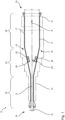
- Fig. 1:
- eine schematische Darstellung einer ersten Ausführungsform einer erfindungsgemäßen Reckanlage,
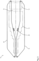
- Fig. 2:
- eine schematische Darstellung einer zweiten Ausführungsform einer erfindungsgemäßen Reckanlage,
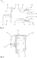
- Figs. 3, 4:
- eine perspektivische Ansicht bzw. Seitenansicht einer ersten Ausführungsform einer erfindungsgemäßen Kluppeneinheit,
- Fig. 5:
- die separaten Grundkörper der Kluppeneinheit gemäß
Figur 3 , - Fig. 6:
- den Grundkörper des Hauptteils der Kluppeneinheit gemäß
Figur 4 in perspektivischer Ansicht, und - Fig. 7:
- eine Seitenansicht einer zweiten Ausführungsform einer erfindungsgemäßen Kluppeneinheit.
- Die Reckanlage 10 weist einen Ofen 14 sowie zwei Antriebssysteme 16 auf.
- Die Antriebssysteme 16 sind gegenüber einer Symmetrieachse S der Reckanlage 10 spiegelsymmetrisch angeordnet und erstrecken sich zumindest teilweise im Ofen 14. In einer Einlaufzone 18 sowie einer Auslaufzone 20, in denen die Materialbahn 12 der Reckanlage 10 zu- bzw. abgeführt wird, verlaufen die Antriebssysteme 16 außerhalb des Ofens 14.
- Neben der Einlaufzone 18 und der Auslaufzone 20 weist die Reckanlage zumindest drei weitere Zonen 22, 24, 26 auf.
- Die Zonen 22, 24, 26 grenzen aneinander an, sodass - entlang der üblicher Bewegungs- bzw. Abzugsrichtung R der Reckanlage 10 betrachtet - an die Einlaufzone 18 zunächst die erste Zone 22, dann die zweite Zone 24, dann die dritte Zone 26, und schließlich die Auslaufzone 20 anschließt.
- In der an die Einlaufzone 18 angrenzenden ersten Zone 22 der Reckanlage 10, auch Vorheizzone genannt, haben die Antriebssysteme 16 einen ersten Abstand zueinander.
- In der zweiten Zone 24, auch Reckzone genannt, vergrößert sich der Abstand der beiden Antriebssysteme 16 zueinander, bis schließlich zu Beginn der dritten Zone 26, auch Wärmebehandlungszone genannt, ein zweiter Abstand erreicht ist.
- Jedes der Antriebssysteme 16 hat in an sich bekannter Weise eine Schiene 17, an der eine Vielzahl von Kluppeneinheiten 28 geführt sind. Die Kluppeneinheiten 28 können durch einen Antrieb des jeweiligen Antriebssystems 16 entlang der Schiene 17 bewegt werden.
- In den
Figuren 1 und2 sind jeweils nur zwei Kluppeneinheiten 28 pro Antriebssystem 16 symbolisch dargestellt. Die Reckanlage 10 weist jedoch mehr Kluppeneinheiten 28 auf. - Die Schienen 17 der jeweiligen Antriebssysteme 16 beschreiben eine geschlossene Bahn von der Einlaufzone 18 zur Auslaufzone 20 und zurück. Der Schienenabschnitt, der den Vorlauf bildet, erstreckt sich in vorgesehener Bewegungsrichtung der Kluppeneinheiten 28 zwischen der Einlaufzone 18 und der Auslaufzone 20 innerhalb des Ofens 14.
- Der Schienenabschnitt, der in üblicher Betriebsrichtung von der Auslaufzone 20 zur Einlaufzone 18 verläuft und den Rücklauf bildet, ist im gezeigten Ausführungsbeispiel ebenfalls innerhalb des Ofens 14 angeordnet. Er kann jedoch auch, wie in der Ausführungsform nach
Figur 2 gezeigt, außerhalb des Ofens 14 angeordnet sein. - Zum Betrieb der Reckanlage 10 wird die zu reckende Materialbahn 12 in der Einlaufzone 18 der Reckanlage 10 in Abzugsrichtung R zugeführt. Hierzu wird die Materialbahn 12 mittels ihrer in Abzugsrichtung R verlaufenden Kanten an beiden Antriebssysteme 16 befestigt.
- Genauer gesagt werden die Ränder der Materialbahn 12 durch eine Klemmvorrichtung 30 (
Fig. 3 ) der Kluppeneinheiten 28 fixiert und somit durch die Bewegung der Kluppeneinheiten 28 entlang der Schienen 17 des Antriebssysteme 16 bewegt. - In der Einlaufzone 18 hat die Materialbahn 12 eine Breite E senkrecht zur Abzugsrichtung R, die in etwa dem ersten Abstand zwischen den Antriebssystemen 16 entspricht.
- Die Materialbahn 12 wird dann durch die erste Zone 22 geführt und dort erwärmt. In der anschließenden zweiten Zone 24, also der Reckzone, wird die Materialbahn 12 gereckt, da sich der Abstand der Antriebssysteme 16 kontinuierlich vergrößert. Zum Ende der zweiten Zone 24 weist die Materialbahn 12 eine zweite Breite A auf.
- Nach erfolgter Reckung durchläuft die Materialbahn 12 nun die dritte Zone 26, bei der eine Relaxierung der Materialbahn 12 erfolgen kann, bevor die Materialbahn 12 in der Auslaufzone 20 von den Kluppeneinheiten 28 gelöst wird und sie die Reckanlage 10 mit der Breite A verlässt.
- Beispielsweise ist die Reckanlage 10 eine Folien-Breit- bzw. Quer-Reckanlage, die kurz als TDO (TDO = transverse direction oven) bezeichnet wird.
- Denkbar ist auch, dass die Reckanlage 10 eine Simultanreckanlage ist, in der die Materialbahn 12 in der zweiten Zone 24, also der Reckzone, nicht nur in Richtung quer zur Abzugsrichtung R sondern auch in der Abzugsrichtung R gereckt werden kann.
- Während der Verarbeitung der Materialbahn 12 wirken vor allem in der zweiten Zone 24, also der Reckzone, auf die Kluppeneinheiten 28 große Zugkräfte in eine Zugrichtung. Die Zugrichtung hat eine überwiegende Komponente in eine Primärrichtung P der Kluppeneinheiten 28 und eine kleinere Komponente quer zur Primärrichtung P.
- Die Kluppeneinheiten 28 müssen somit daher dazu ausgebildet sein, die hohen auftretenden Zugkräfte auszuhalten, insbesondere in ihrer Primärrichtung P.
- Die Primärrichtung P ist dabei diejenige horizontale Richtung, die quer zu einer in der Kluppeneinheit 28 aufgenommenen Kante der Materialbahn 12 verläuft.
- In den
Figuren 3 und 4 ist eine der Kluppeneinheiten 28 beispielhaft in einer perspektivischen Ansicht bzw. teilweise im Schnitt in einer Seitenansicht dargestellt. Die Kluppeneinheit 28 weist ein Hauptteil 32 sowie zwei Führungsteile 34 auf, wobei das Hauptteil 32 und die Führungsteile 34 als voneinander separate Bauteile urgeformt und anschließend aneinander befestigt werden. Die Kluppeneinheit 28 ist somit mehrteilig. - Das Hauptteil 32 hat einen Grundkörper 36 und weist die Klemmvorrichtung 30 auf.
- Die Seite des Grundkörpers 36, an der die Klemmvorrichtung 30 vorgesehen ist, wird auch Materialseite genannt. Die andere Seite, d. h. die Seite des Grundkörpers 36 ohne die Klemmvorrichtung 30, wird Führungsseite genannt, da an dieser Seite die Führungsteile 34 befestigt sind.
- Dementsprechend weist auch das Hauptteil 32 eine Materialseite und eine Führungsseite auf.
- Die Klemmvorrichtung 30 ist im gezeigten Ausführungsbeispiel aus Abschnitten des Grundkörpers 36 und am Grundkörper 36 rotierbar befestigten Messerklappe 38 in an sich bekannter Weise ausgebildet.
- Die Klemmvorrichtung 30 definiert einen Befestigungsabschnitt 40 bzw. Befestigungsmund, in den der zu befestigende Rand der Materialbahn 12 eingeführt und mittels der Messerklappe 38 an der Kluppeneinheit 28 fixiert werden kann.
- Die Primärrichtung P der Kluppeneinheit 28 ist senkrecht zum Rand bzw. der Kante der Materialbahn, die in der Kluppeneinheit 28 fixiert ist. Die Primärrichtung P verläuft beispielsweise in der
Figur 4 nach links. - Der Grundkörper 36 ist beispielsweise zumindest im Bereich des Befestigungsabschnitt 40 verzinkt oder vernickelt.
- Eine befestigte Materialbahn 12 übt in der zweiten Zone 24 (Reckzone) eine Zugkraft in der Zugrichtung auf die Kluppeneinheit 28 aus.
- Die Führungsteile 34 weisen jeweils einen Grundkörper 42 sowie jeweils wenigstens ein Führungselement 44 auf, das am Grundkörper 42 befestigt ist.
- In der ersten Ausführungsform weisen die Führungsteile 34 zudem ein Antriebselement 46 auf, das beispielsweise eine Kette bzw. Teile einer Kette des Antriebssystems 16 ist bzw. ist.
- Das Antriebselement 46 kann auch ein Eingriffsvorsprung für einen Riemen des Antriebssystems 16 oder Teil eines Linearmotors sein.
- Im gezeigten Ausführungsbeispiel sind die Führungselemente 44 als Rollen ausgebildet. Die Führungselemente 44 können in anderen Ausführungsformen jedoch auch Gleitelemente und/oder magnetische Elemente, wie ein Permanentmagnet oder ein ferromagnetisches Gegenstück, sein.
- Die Führungsteile 34 definieren eine Aufnahme 48 für die Schiene 17 (auch Führungsschiene genannt). Insbesondere können in den Grundkörpern 42 der Führungsteile 34 je eine Ausnehmung vorgesehen sein, in die die Schiene 17 eingreift.
- Die Aufnahme 48 ist dementsprechend vor bzw. auf der Führungsseite des Hauptteils 32 angeordnet.
- Die Führungselemente 44, insbesondere Rollen und ggf. Gleitelemente, können in die Aufnahme 48 hineinragen und an der Schiene 17 anliegen und als Führung an der Schiene dienen.
- In
Figur 5 sind die Grundkörper 36, 42 des Hauptteils 32 bzw. der Führungsteile 34 separat und einzeln dargestellt, beispielsweise wie sie direkt nach ihrer Herstellung, z.B. Urformung sind. - In
Figur 6 ist lediglich der Grundkörper 36 des Hauptteils 32 von der Führungsseite aus betrachtet dargestellt. - Die Grundkörper 36, 42 sind aus Metall, beispielsweise G26CrMo4 oder G42CrMo4, und durch ein Gussverfahren, ein Schmiedeverfahren hergestellt oder als Bearbeitungsteil ausgeführt.
- Die Grundkörper 42 der Führungsteile 34 haben zudem Befestigungselemente 58, wie Vorsprünge, Ausnehmungen und/oder Vertiefungen, an denen die Führungselemente 44 und/oder Antriebselemente 46 befestigt sein können.
- Die Befestigungselemente 58 können dabei an die Aufnahme 48 angrenzen oder erstrecken sich in die Aufnahme 48 hinein.
- Die Grundkörper 42 der Führungsteile 34 und der Grundkörper 36 des Hauptteils 32 liegen an Anlageflächen 50 aneinander an und werden mittels Schrauben 52, beispielsweise Passschrauben, der Kluppeneinheit 28 aneinander befestigt.
- Die Schrauben 52 sind zum Beispiel dazu ausgelegt, eine Maximalkraft zwischen 700N und 900N, insbesondere von 800N aufnehmen zu können. Auch ist es denkbar, dass die Schrauben höhere Kräfte aufnehmen können.
- Wie in
Figur 4 zu erkennen, erstrecken sich die Schrauben 52 (annähernd) parallel zur Primärrichtung P. Die Anlageflächen 50 erstrecken sich, wie sie beispielsweise am Grundkörper 36 des Hauptteils 32 inFigur 6 zu sehen sind, senkrecht zur Primärrichtung P. - Die Anlageflächen 50 sind somit entlang der Primärrichtung P zwischen der Klemmvorrichtung 30 und der Aufnahme 48 angeordnet.
- Die Grundkörper 42 der Führungsteile 34 sind somit an der Führungsseite des Hauptteils 32 vorgesehen und erstrecken sich vom Grundkörper 36 des Hauptteils 32 parallel zur Primärrichtung P. Die Führungsteile 34 bzw. deren Grundkörper 42 verlaufen somit parallel zueinander.
- Die Grundkörper 36, 42 des Hauptteils 32 bzw. der Führungsteile 34 bilden zusammen eine U-Form - in einer Seitenansicht und/oder einem Querschnitt durch die Kluppeneinheit 28 -, sodass die Kluppeneinheit 28 eine U-Form hat.
- Die U-Form hat eine Basis 54 sowie zwei Schenkel 56, wobei im gezeigten Ausführungsform die Basis 54 durch den Grundkörper 36 des Führungsteils 34 und die Schenkel durch jeweils einen der Grundkörper 42 der Führungsteile 34 gebildet sind.
- Die Basis 54 erstreckt sich senkrecht zu den Schenkeln 56. Die Schenkel 56 erstrecken sich wiederum parallel zur Primärrichtung P.
- Dadurch, dass die Grundkörper 36, 42 jeweils kompakter und im Vergleich zur gesamten Kluppeneinheit 28 wesentlich weniger komplexe Geometrien aufweisen - die Grundkörper 42 der Führungsteile 34 können im weitesten Sinne als plattenförmig angesehen werden -, können mehr Grundkörper 36, 42 an einem Gussbaum vorgesehen werden, wodurch sich die Produktionskosten erheblich verringern, zum Beispiel gegenüber einteiligen und ggf. zweiteiligen Kluppeneinheiten. Zudem ist der Aufwand, drei Grundkörper zu gießen, wesentlich geringer, da die Geometrien einfacher gestaltet werden können.
- Durch die separate Ausführung der Grundkörper 36, 42 ist die Herstellung der Grundkörper 36, 42 stark vereinfacht. Auch weitere benötigte Prozessschritte, wie die Verzinkung des Grundkörpers 36 im Bereich des Befestigungsabschnittes 40 können einfacher und somit kostengünstiger durchgeführt werden.
- In
Figur 7 ist eine weitere Ausführungsformen der Erfindung dargestellt. Die weitere Ausführungsform entspricht im Wesentlichen der zuvor beschriebenen Ausführungsform der Kluppeneinheit 28, sodass im Folgenden lediglich auf die Unterschiede eingegangen wird. Gleiche und funktionsgleiche Teile sind mit denselben Bezugszeichen versehen. - In
Figur 7 ist eine mehrteilige Kluppeneinheit 28 gemäß einer zweiten Ausführungsform in einer teilweisen Schnittansicht ähnlich derFigur 4 dargestellt. - Im Gegensatz zur ersten Ausführungsform verlaufen die Schrauben 52 zur Befestigung des Grundkörpers 42 einer der Führungsteile 34 am Hauptteil 32 nicht parallel zur Primärrichtung P sondern schräg hierzu.
- Außerdem ist die Anlagefläche 50 (in
Figur 7 hervorgehoben) nicht ausschließlich senkrecht zur Primärrichtung P, sondern weist einen Abschnitt parallel zur Primärrichtung P auf. Dadurch wird die Montage vereinfacht aber auch die Stabilität der Kluppeneinheit 28 erhöht. - Der überwiegende Anteil der Anlagefläche 50 verläuft jedoch senkrecht zur Primärrichtung P.
Claims (12)
- Mehrteilige Kluppeneinheit für eine Reckanlage, insbesondere eine Quer-, Längs- und/oder Simultan-Reckanlage (10), mit einem Hauptteil (32) und wenigstens zwei Führungsteilen (34),wobei das Hauptteil (32) einen Grundkörper (36) sowie eine Klemmvorrichtung (30) zum Klemmen einer Materialbahn (12) aufweist, und die Führungsteile (34) jeweils einen Grundkörper (42) sowie wenigstens ein Führungselement (44) zur Führung an einer Schiene (17) der Reckanlage (10) aufweisen, undwobei die Grundkörper (42) der Führungsteile (34) und der Grundkörper (36) des Hauptteils (32) jeweils als separate Bauteile hergestellt sind und aneinander befestigt sind.
- Kluppeneinheit nach Anspruch 1, dadurch gekennzeichnet, dass die Grundkörper (42) der Führungsteile (34) und/oder der Grundkörper (36) des Hauptteils (32) aus Metall sind und/oder durch ein Gussverfahren hergestellt sind.
- Kluppeneinheit nach Anspruch 1 oder 2, dadurch gekennzeichnet, dass die Kluppeneinheit (28) eine Primärrichtung (P) aufweist, insbesondere wobei sich die Grundkörper (42) der Führungsteile (34) parallel zur Primärrichtung (P) erstrecken.
- Kluppeneinheit nach Anspruch 3, dadurch gekennzeichnet, dass die Anlagefläche (50) zwischen dem Grundkörper (42) einer der Führungsteile (34) und dem Grundkörper (36) des Hauptteils (32) senkrecht zur Primärrichtung (P) verläuft.
- Kluppeneinheit nach einem der vorhergehenden Ansprüche, dadurch gekennzeichnet, dass die Grundkörper (42) der Führungsteile (34) mittels Schrauben (52) der Kluppeneinheit (28) am Hauptteil (32) befestigt sind, insbesondere wobei die Schrauben (52) parallel zur Primärrichtung (P) verlaufen.
- Kluppeneinheit nach einem der vorhergehenden Ansprüche, dadurch gekennzeichnet, dass die Kluppeneinheit (28) eine U-Form mit einer Basis (54) und zwei Schenkeln (56) hat, insbesondere wobei der Grundkörper (36) des Hauptteils (32) die Basis (54) und die Grundkörper (42) der Führungsteile (34) jeweils einen der Schenkel (56) bilden.
- Kluppeneinheit nach einem der vorhergehenden Ansprüche, dadurch gekennzeichnet, dass das Hauptteil (32) eine Materialseite und eine Führungsseite aufweist, wobei die Klemmvorrichtung (30) an der Materialseite vorgesehen ist und/oder dass die Führungssteile (34) an der Führungsseite am Hauptteil (32) befestigt ist.
- Kluppeneinheit nach einem der vorhergehenden Ansprüche, dadurch gekennzeichnet, dass die Kluppeneinheit (28) eine Aufnahme (48) aufweist, die zumindest durch die Führungsteile (34) begrenzt ist, wobei die Anlagefläche (50) der Grundkörper (36, 42) zwischen der Klemmvorrichtung (30) und der Aufnahme (48) angeordnet ist.
- Kluppeneinheit nach Anspruch 8, dadurch gekennzeichnet, dass die Aufnahme (48) vor der Führungsseite des Hauptteils (32) angeordnet ist und/oder das Hauptteil (32) und die Führungsteile (34) die Aufnahme (48) definieren.
- Kluppeneinheit nach einem der vorhergehenden Ansprüche, dadurch gekennzeichnet, dass an den Grundkörpern (42) der Führungsteile (34) jeweils wenigstens ein Befestigungselement (58) zur Befestigung des Führungselements (44) und/oder eines Antriebselements (46) ausgebildet ist, insbesondere wobei das wenigstens eine Befestigungselement (58) an die Aufnahme (48) angrenzt und/oder sich in die Aufnahme (48) erstreckt.
- Kluppeneinheit nach einem der vorhergehenden Ansprüche, dadurch gekennzeichnet, dass das Führungselement (44) eine Rolle, ein Gleitelement und/oder ein magnetisches Element ist, und/oder wobei das Antriebselement (46) eine Kette, Teile einer Kette, ein Teil eines Linearmotors und/oder ein Eingriffsvorsprung für einen Riemen eines Antriebssystems (16) der Reckanlage (10) ist.
- Reckanlage, insbesondere Quer-, Längs- und/oder Simultan-Reckanlage, mit einer Schiene (17) und wenigstens einer mehrteiligen Kluppeneinheit (28) gemäß einem der vorhergehenden Ansprüche, wobei die Kluppeneinheit (28) mittels des Führungselements (44) an der Schiene (17) geführt ist.
Applications Claiming Priority (1)
| Application Number | Priority Date | Filing Date | Title |
|---|---|---|---|
| DE102021117782.0A DE102021117782A1 (de) | 2021-07-09 | 2021-07-09 | Mehrteilige Kluppeneinheit sowie Reckanlage |
Publications (4)
| Publication Number | Publication Date |
|---|---|
| EP4155057A2 true EP4155057A2 (de) | 2023-03-29 |
| EP4155057A3 EP4155057A3 (de) | 2023-09-13 |
| EP4155057B1 EP4155057B1 (de) | 2025-03-26 |
| EP4155057C0 EP4155057C0 (de) | 2025-03-26 |
Family
ID=82399227
Family Applications (1)
| Application Number | Title | Priority Date | Filing Date |
|---|---|---|---|
| EP22183283.5A Active EP4155057B1 (de) | 2021-07-09 | 2022-07-06 | Mehrteilige kluppeneinheit sowie reckanlage |
Country Status (7)
| Country | Link |
|---|---|
| US (1) | US20230008385A1 (de) |
| EP (1) | EP4155057B1 (de) |
| JP (1) | JP7490716B2 (de) |
| KR (1) | KR102937237B1 (de) |
| CN (1) | CN115592933B (de) |
| DE (1) | DE102021117782A1 (de) |
| MX (1) | MX2022008530A (de) |
Family Cites Families (18)
| Publication number | Priority date | Publication date | Assignee | Title |
|---|---|---|---|---|
| NL288416A (de) * | 1962-02-01 | |||
| DE3339150A1 (de) * | 1983-10-28 | 1985-05-09 | H. Krantz Gmbh & Co, 5100 Aachen | Kombinierte nadel-kluppenkette |
| US4939825A (en) * | 1989-05-10 | 1990-07-10 | Mobil Oil Corporation | Lightweight tenter frame clip |
| JPH0764022B2 (ja) * | 1993-05-27 | 1995-07-12 | 東レ株式会社 | シート状物の製造方法 |
| DE19515036A1 (de) | 1995-04-24 | 1996-10-31 | Brueckner Maschbau | Transportvorrichtung sowie zugehörige Führungsschiene |
| DE102008021506A1 (de) * | 2008-04-30 | 2009-11-05 | Lindauer Dornier Gmbh | Vorrichtung zum Querrecken von Folienbahnen |
| JP5371523B2 (ja) * | 2009-04-14 | 2013-12-18 | 東芝機械株式会社 | フィルム延伸装置およびフィルムの延伸方法 |
| DE102012025486A1 (de) * | 2012-12-20 | 2014-06-26 | Brückner Maschinenbau GmbH & Co. KG | Kluppen-Transporteinheit |
| CN203019679U (zh) | 2012-12-26 | 2013-06-26 | 桂林电器科学研究院 | 塑料膜拉伸生产线的厚膜链铗 |
| DE102013017011A1 (de) * | 2013-10-14 | 2015-04-30 | Brückner Maschinenbau GmbH & Co. KG | Kluppen-Transporteinheit |
| CN203557704U (zh) * | 2013-11-01 | 2014-04-23 | 桂林电器科学研究院有限公司 | 塑料膜拉伸生产线双链条的链铗系统 |
| CN203556680U (zh) * | 2013-11-22 | 2014-04-23 | 包头市丰达石油机械有限责任公司 | 抽油杆热拉校直机的机械结构 |
| JP2015208860A (ja) * | 2014-04-23 | 2015-11-24 | 住友電気工業株式会社 | フィルム搬送装置用クリップ及びフィルム搬送装置、並びに合成樹脂膜の製造方法 |
| FR3063670B1 (fr) * | 2017-03-10 | 2019-03-29 | Carolina MARCHANTE | Dispositif d’etirage pour etirer un film en matiere synthetique au moins dans un sens transversal |
| WO2020077993A1 (zh) | 2018-10-15 | 2020-04-23 | 佛山市盟思拉伸机械有限公司 | 高速薄膜横向拉伸设备及纵向热定型机构 |
| CN209616330U (zh) * | 2019-01-17 | 2019-11-12 | 山东永健机械有限公司 | 一种稳定性好的链铗 |
| CN209888134U (zh) * | 2019-03-22 | 2020-01-03 | 尹斓 | 一种流延膜横向拉伸设备 |
| DE102019127701A1 (de) * | 2019-10-15 | 2021-04-15 | Brückner Maschinenbau GmbH & Co. KG | Kluppenwagen für eine Transportkettenanordnung einer Reckanlage sowie eine zugehörige Reckanlage |
-
2021
- 2021-07-09 DE DE102021117782.0A patent/DE102021117782A1/de active Pending
-
2022
- 2022-07-06 EP EP22183283.5A patent/EP4155057B1/de active Active
- 2022-07-06 CN CN202210795914.6A patent/CN115592933B/zh active Active
- 2022-07-07 KR KR1020220083724A patent/KR102937237B1/ko active Active
- 2022-07-07 JP JP2022109403A patent/JP7490716B2/ja active Active
- 2022-07-08 MX MX2022008530A patent/MX2022008530A/es unknown
- 2022-07-08 US US17/861,038 patent/US20230008385A1/en active Pending
Also Published As
| Publication number | Publication date |
|---|---|
| US20230008385A1 (en) | 2023-01-12 |
| KR102937237B1 (ko) | 2026-03-09 |
| CN115592933B (zh) | 2026-07-03 |
| EP4155057B1 (de) | 2025-03-26 |
| EP4155057C0 (de) | 2025-03-26 |
| DE102021117782A1 (de) | 2023-01-12 |
| JP7490716B2 (ja) | 2024-05-27 |
| EP4155057A3 (de) | 2023-09-13 |
| MX2022008530A (es) | 2023-01-10 |
| JP2023011519A (ja) | 2023-01-24 |
| CN115592933A (zh) | 2023-01-13 |
| KR20230009843A (ko) | 2023-01-17 |
Similar Documents
| Publication | Publication Date | Title |
|---|---|---|
| DE69307094T2 (de) | Strangpressmatrize und Matrizeeinsatz dafür | |
| DE69415094T2 (de) | Translations/rotations-fördersystem für tragelement | |
| EP0705649A1 (de) | Verfahren zur Herstellung eines Flach- oder Zentripetalsiebes | |
| DE3720214A1 (de) | Spritzgiessmaschine | |
| DE102010001146B4 (de) | Kettenschiene für Einziehketten und ein Verfahren zur Herstellung einer Kettenschiene | |
| EP3769923B1 (de) | Führungsschiene für eine motorkettensäge und verfahren zur herstellung einer führungsschiene | |
| DE1278305B (de) | Trag- und Belastungsarm fuer Streckwerke von Spinnereimaschinen | |
| EP2999815B1 (de) | Schiebernadel | |
| WO2001058669A1 (de) | Vorrichtung zur herstellung von profilierten kunststoff-rohren | |
| EP3057769B1 (de) | Kluppen-transporteinheit | |
| EP4155057B1 (de) | Mehrteilige kluppeneinheit sowie reckanlage | |
| WO2020208142A1 (de) | Steckzunge für einen sicherheitsgurt | |
| DE102008021802A1 (de) | Türführung eines Fahrzeuges und Verfahren zu deren Herstellung | |
| DE29810317U1 (de) | Formblock zur Verwendung in einem beweglichen Formtunnel | |
| DE2007593A1 (de) | Vorrichtung zur Thermofixierung von Reißverschlußghederreihen | |
| DE3048228A1 (de) | Waelzlager zur laengsbeweglichen lagerung eines teiles mit einer geraden laufbahn | |
| DE112014004081B4 (de) | Bewegungsführungseinrichtung | |
| EP1336468B1 (de) | Zahnriemen aus Kunststoff und Verfahren und Vorrichtung zum Herstellen eines Zahnriemens | |
| EP3074649B1 (de) | Abstandshalter für eine gleitführung und hubsäule | |
| DE102012014440B3 (de) | Induktor | |
| DE102016223233A1 (de) | Wälzkörpergewindetrieb mit radial eingesetzten, einstückigen Umlenkelementen | |
| DE202017101044U1 (de) | Entnahmevorrichtung und Bürstenherstellungsmaschine mit einer solchen | |
| DE29915058U1 (de) | Gurteinfügungs- bzw. -durchführungsteil | |
| DE3208046A1 (de) | Kurbelwellenbearbeitungsmaschine | |
| DE102024105010A1 (de) | Schlosszunge |
Legal Events
| Date | Code | Title | Description |
|---|---|---|---|
| PUAI | Public reference made under article 153(3) epc to a published international application that has entered the european phase |
Free format text: ORIGINAL CODE: 0009012 |
|
| STAA | Information on the status of an ep patent application or granted ep patent |
Free format text: STATUS: THE APPLICATION HAS BEEN PUBLISHED |
|
| AK | Designated contracting states |
Kind code of ref document: A2 Designated state(s): AL AT BE BG CH CY CZ DE DK EE ES FI FR GB GR HR HU IE IS IT LI LT LU LV MC MK MT NL NO PL PT RO RS SE SI SK SM TR |
|
| RAP3 | Party data changed (applicant data changed or rights of an application transferred) |
Owner name: BRUECKNER MASCHINENBAU GMBH |
|
| PUAL | Search report despatched |
Free format text: ORIGINAL CODE: 0009013 |
|
| AK | Designated contracting states |
Kind code of ref document: A3 Designated state(s): AL AT BE BG CH CY CZ DE DK EE ES FI FR GB GR HR HU IE IS IT LI LT LU LV MC MK MT NL NO PL PT RO RS SE SI SK SM TR |
|
| RIC1 | Information provided on ipc code assigned before grant |
Ipc: B29C 55/20 20060101AFI20230804BHEP |
|
| STAA | Information on the status of an ep patent application or granted ep patent |
Free format text: STATUS: REQUEST FOR EXAMINATION WAS MADE |
|
| 17P | Request for examination filed |
Effective date: 20240308 |
|
| RBV | Designated contracting states (corrected) |
Designated state(s): AL AT BE BG CH CY CZ DE DK EE ES FI FR GB GR HR HU IE IS IT LI LT LU LV MC MK MT NL NO PL PT RO RS SE SI SK SM TR |
|
| GRAP | Despatch of communication of intention to grant a patent |
Free format text: ORIGINAL CODE: EPIDOSNIGR1 |
|
| STAA | Information on the status of an ep patent application or granted ep patent |
Free format text: STATUS: GRANT OF PATENT IS INTENDED |
|
| INTG | Intention to grant announced |
Effective date: 20241017 |
|
| GRAS | Grant fee paid |
Free format text: ORIGINAL CODE: EPIDOSNIGR3 |
|
| GRAA | (expected) grant |
Free format text: ORIGINAL CODE: 0009210 |
|
| STAA | Information on the status of an ep patent application or granted ep patent |
Free format text: STATUS: THE PATENT HAS BEEN GRANTED |
|
| AK | Designated contracting states |
Kind code of ref document: B1 Designated state(s): AL AT BE BG CH CY CZ DE DK EE ES FI FR GB GR HR HU IE IS IT LI LT LU LV MC MK MT NL NO PL PT RO RS SE SI SK SM TR |
|
| REG | Reference to a national code |
Ref country code: GB Ref legal event code: FG4D Free format text: NOT ENGLISH |
|
| REG | Reference to a national code |
Ref country code: CH Ref legal event code: EP |
|
| REG | Reference to a national code |
Ref country code: DE Ref legal event code: R096 Ref document number: 502022003304 Country of ref document: DE |
|
| REG | Reference to a national code |
Ref country code: IE Ref legal event code: FG4D Free format text: LANGUAGE OF EP DOCUMENT: GERMAN |
|
| U01 | Request for unitary effect filed |
Effective date: 20250422 |
|
| U07 | Unitary effect registered |
Designated state(s): AT BE BG DE DK EE FI FR IT LT LU LV MT NL PT RO SE SI Effective date: 20250430 |
|
| PG25 | Lapsed in a contracting state [announced via postgrant information from national office to epo] |
Ref country code: RS Free format text: LAPSE BECAUSE OF FAILURE TO SUBMIT A TRANSLATION OF THE DESCRIPTION OR TO PAY THE FEE WITHIN THE PRESCRIBED TIME-LIMIT Effective date: 20250626 |
|
| PG25 | Lapsed in a contracting state [announced via postgrant information from national office to epo] |
Ref country code: NO Free format text: LAPSE BECAUSE OF FAILURE TO SUBMIT A TRANSLATION OF THE DESCRIPTION OR TO PAY THE FEE WITHIN THE PRESCRIBED TIME-LIMIT Effective date: 20250626 |
|
| PG25 | Lapsed in a contracting state [announced via postgrant information from national office to epo] |
Ref country code: HR Free format text: LAPSE BECAUSE OF FAILURE TO SUBMIT A TRANSLATION OF THE DESCRIPTION OR TO PAY THE FEE WITHIN THE PRESCRIBED TIME-LIMIT Effective date: 20250326 |
|
| PG25 | Lapsed in a contracting state [announced via postgrant information from national office to epo] |
Ref country code: GR Free format text: LAPSE BECAUSE OF FAILURE TO SUBMIT A TRANSLATION OF THE DESCRIPTION OR TO PAY THE FEE WITHIN THE PRESCRIBED TIME-LIMIT Effective date: 20250627 |
|
| U20 | Renewal fee for the european patent with unitary effect paid |
Year of fee payment: 4 Effective date: 20250729 |
|
| PG25 | Lapsed in a contracting state [announced via postgrant information from national office to epo] |
Ref country code: SM Free format text: LAPSE BECAUSE OF FAILURE TO SUBMIT A TRANSLATION OF THE DESCRIPTION OR TO PAY THE FEE WITHIN THE PRESCRIBED TIME-LIMIT Effective date: 20250326 |
|
| PG25 | Lapsed in a contracting state [announced via postgrant information from national office to epo] |
Ref country code: ES Free format text: LAPSE BECAUSE OF FAILURE TO SUBMIT A TRANSLATION OF THE DESCRIPTION OR TO PAY THE FEE WITHIN THE PRESCRIBED TIME-LIMIT Effective date: 20250326 |
|
| PG25 | Lapsed in a contracting state [announced via postgrant information from national office to epo] |
Ref country code: PL Free format text: LAPSE BECAUSE OF FAILURE TO SUBMIT A TRANSLATION OF THE DESCRIPTION OR TO PAY THE FEE WITHIN THE PRESCRIBED TIME-LIMIT Effective date: 20250326 |
|
| PG25 | Lapsed in a contracting state [announced via postgrant information from national office to epo] |
Ref country code: SK Free format text: LAPSE BECAUSE OF FAILURE TO SUBMIT A TRANSLATION OF THE DESCRIPTION OR TO PAY THE FEE WITHIN THE PRESCRIBED TIME-LIMIT Effective date: 20250326 |
|
| PG25 | Lapsed in a contracting state [announced via postgrant information from national office to epo] |
Ref country code: IS Free format text: LAPSE BECAUSE OF FAILURE TO SUBMIT A TRANSLATION OF THE DESCRIPTION OR TO PAY THE FEE WITHIN THE PRESCRIBED TIME-LIMIT Effective date: 20250726 |
|
| PG25 | Lapsed in a contracting state [announced via postgrant information from national office to epo] |
Ref country code: CZ Free format text: LAPSE BECAUSE OF FAILURE TO SUBMIT A TRANSLATION OF THE DESCRIPTION OR TO PAY THE FEE WITHIN THE PRESCRIBED TIME-LIMIT Effective date: 20250326 |
|
| PLBE | No opposition filed within time limit |
Free format text: ORIGINAL CODE: 0009261 |
|
| STAA | Information on the status of an ep patent application or granted ep patent |
Free format text: STATUS: NO OPPOSITION FILED WITHIN TIME LIMIT |
|
| REG | Reference to a national code |
Ref country code: CH Ref legal event code: L10 Free format text: ST27 STATUS EVENT CODE: U-0-0-L10-L00 (AS PROVIDED BY THE NATIONAL OFFICE) Effective date: 20260211 |
|
| REG | Reference to a national code |
Ref country code: CH Ref legal event code: H13 Free format text: ST27 STATUS EVENT CODE: U-0-0-H10-H13 (AS PROVIDED BY THE NATIONAL OFFICE) Effective date: 20260224 |
|
| 26N | No opposition filed |
Effective date: 20260105 |
|
| PG25 | Lapsed in a contracting state [announced via postgrant information from national office to epo] |
Ref country code: CH Free format text: LAPSE BECAUSE OF NON-PAYMENT OF DUE FEES Effective date: 20250731 |
|
| PG25 | Lapsed in a contracting state [announced via postgrant information from national office to epo] |
Ref country code: IE Free format text: LAPSE BECAUSE OF NON-PAYMENT OF DUE FEES Effective date: 20250706 |
|
| PG25 | Lapsed in a contracting state [announced via postgrant information from national office to epo] |
Ref country code: MC Free format text: LAPSE BECAUSE OF FAILURE TO SUBMIT A TRANSLATION OF THE DESCRIPTION OR TO PAY THE FEE WITHIN THE PRESCRIBED TIME-LIMIT Effective date: 20250326 |
|
| PG25 | Lapsed in a contracting state [announced via postgrant information from national office to epo] |
Ref country code: CY Free format text: LAPSE BECAUSE OF FAILURE TO SUBMIT A TRANSLATION OF THE DESCRIPTION OR TO PAY THE FEE WITHIN THE PRESCRIBED TIME-LIMIT Effective date: 20250326 |
|
| U20 | Renewal fee for the european patent with unitary effect paid |
Year of fee payment: 5 Effective date: 20260709 |