EP4153805B1 - Gerät zum trocknen und/oder waschen von wäsche mit einem autonomen feuerlöschsystem - Google Patents
Gerät zum trocknen und/oder waschen von wäsche mit einem autonomen feuerlöschsystem Download PDFInfo
- Publication number
- EP4153805B1 EP4153805B1 EP21717051.3A EP21717051A EP4153805B1 EP 4153805 B1 EP4153805 B1 EP 4153805B1 EP 21717051 A EP21717051 A EP 21717051A EP 4153805 B1 EP4153805 B1 EP 4153805B1
- Authority
- EP
- European Patent Office
- Prior art keywords
- pipe
- appliance
- drum
- face panel
- fire
- Prior art date
- Legal status (The legal status is an assumption and is not a legal conclusion. Google has not performed a legal analysis and makes no representation as to the accuracy of the status listed.)
- Active
Links
Images


Classifications
-
- D—TEXTILES; PAPER
- D06—TREATMENT OF TEXTILES OR THE LIKE; LAUNDERING; FLEXIBLE MATERIALS NOT OTHERWISE PROVIDED FOR
- D06F—LAUNDERING, DRYING, IRONING, PRESSING OR FOLDING TEXTILE ARTICLES
- D06F37/00—Details specific to washing machines covered by groups D06F21/00 - D06F25/00
- D06F37/42—Safety arrangements, e.g. for stopping rotation of the receptacle upon opening of the casing door
-
- D—TEXTILES; PAPER
- D06—TREATMENT OF TEXTILES OR THE LIKE; LAUNDERING; FLEXIBLE MATERIALS NOT OTHERWISE PROVIDED FOR
- D06F—LAUNDERING, DRYING, IRONING, PRESSING OR FOLDING TEXTILE ARTICLES
- D06F33/00—Control of operations performed in washing machines or washer-dryers
- D06F33/50—Control of washer-dryers characterised by the purpose or target of the control
- D06F33/74—Responding to irregular working conditions, e.g. malfunctioning of pumps
-
- D—TEXTILES; PAPER
- D06—TREATMENT OF TEXTILES OR THE LIKE; LAUNDERING; FLEXIBLE MATERIALS NOT OTHERWISE PROVIDED FOR
- D06F—LAUNDERING, DRYING, IRONING, PRESSING OR FOLDING TEXTILE ARTICLES
- D06F58/00—Domestic laundry dryers
- D06F58/20—General details of domestic laundry dryers
-
- A—HUMAN NECESSITIES
- A62—LIFE-SAVING; FIRE-FIGHTING
- A62C—FIRE-FIGHTING
- A62C3/00—Fire prevention, containment or extinguishing specially adapted for particular objects or places
- A62C3/16—Fire prevention, containment or extinguishing specially adapted for particular objects or places in electrical installations, e.g. cableways
-
- D—TEXTILES; PAPER
- D06—TREATMENT OF TEXTILES OR THE LIKE; LAUNDERING; FLEXIBLE MATERIALS NOT OTHERWISE PROVIDED FOR
- D06F—LAUNDERING, DRYING, IRONING, PRESSING OR FOLDING TEXTILE ARTICLES
- D06F2103/00—Parameters monitored or detected for the control of domestic laundry washing machines, washer-dryers or laundry dryers
-
- D—TEXTILES; PAPER
- D06—TREATMENT OF TEXTILES OR THE LIKE; LAUNDERING; FLEXIBLE MATERIALS NOT OTHERWISE PROVIDED FOR
- D06F—LAUNDERING, DRYING, IRONING, PRESSING OR FOLDING TEXTILE ARTICLES
- D06F2105/00—Systems or parameters controlled or affected by the control systems of washing machines, washer-dryers or laundry dryers
- D06F2105/62—Stopping or disabling machine operation
-
- D—TEXTILES; PAPER
- D06—TREATMENT OF TEXTILES OR THE LIKE; LAUNDERING; FLEXIBLE MATERIALS NOT OTHERWISE PROVIDED FOR
- D06F—LAUNDERING, DRYING, IRONING, PRESSING OR FOLDING TEXTILE ARTICLES
- D06F58/00—Domestic laundry dryers
- D06F58/32—Control of operations performed in domestic laundry dryers
- D06F58/34—Control of operations performed in domestic laundry dryers characterised by the purpose or target of the control
- D06F58/50—Responding to irregular working conditions, e.g. malfunctioning of blowers
Definitions
- the present invention relates to a laundry drying and/or washing appliance equipped with an autonomous fire extinguishing or fire starting system.
- the patent application FR-A1-2 614 209 describes a fire-fighting device for electrical appliances containing flammable components and in particular for a washing machine or dryer.
- a laundry drying and/or washing appliance is a household appliance which comprises a rotating drum in which laundry is placed for washing with water and a cleaning agent, or damp laundry for drying by stirring. .
- the drum is generally rotated by a belt which is itself driven by an electric motor.
- a washing machine can have a dryer function. In both cases, the drum of the device can be passed through by a flow of hot air so as to facilitate the drying of the laundry when it is tossed.
- the heating and hot air flow generation system of the device may include a gas burner or an electric resistance for example.
- This household appliance is the cause of many domestic fires. Heating and stirring the laundry in the drum generates flammable dust which accumulates inside the appliance and which is likely to ignite, particularly when deposited on very hot parts of the appliance. device such as the engine or the heating system. A fire caused by the ignition of dust can cause a larger fire in the device, particularly by ignition of the drum drive belt.
- the patent application mentioned above proposes installing a tank in the form of a pressure bomb in a washing machine, this tank being connected to pipes that are normally closed and likely to rupture at a determined temperature threshold. These pipes extend to parts of the device which are subject to overheating or catching fire, such as electrical devices, resistances, the motor, flammable components, etc.
- the fire-fighting substance contained in the tank is at least slightly under pressure and the distribution pipes are made of a material intended to melt to ensure the rupture or opening of these pipes when the latter are licked by flames or when the temperature of their environment exceeds a predetermined threshold. In this way, as soon as overheating or flammability conditions arise which could give rise to a fire inside the device, the pipes break and automatically distribute the fire-fighting substance to immediately extinguish the possible development of a fire.
- the solution described in this patent application is, however, not entirely satisfactory because the fire extinguishing system formed by the tank and the pipes is complex and takes a long time to install in a household appliance. In fact, it includes several elements which must be installed and fixed one after the other and connected to each other in the device. These elements are located in several areas inside the device so that the installation of the system in the device can only be done during the manufacture of this device. Likewise, in the event of maintenance, it is necessary to dismantle several front panels of the device to access the system. The system described in this application cannot therefore easily be integrated into an existing device which would not have been originally designed to be equipped with this system.
- the state of the art also includes the document US-B2-9,885,142 .
- the present invention proposes a solution to at least part of the problems mentioned in the above, which is simple, effective and economical and allows both simple and rapid integration into the specific environment of a laundry drying and/or washing appliance.
- the pipe also has its two ends which are closed in a watertight manner.
- the pipe has an elongated shape and is made of a material facilitating on the one hand its shaping by heating (called thermoforming), before its assembly in the device, as well as allowing the release of the extinguishing fluid by melting and bursting.
- the pipe is arranged in two portions.
- a first portion of the pipe forms a cradle extending between the drum and the motor.
- a cradle generally has a rounded or hollow shape, which allows it to extend around the drum and conform to its shape.
- the pipe forms a loop which allows it to extend over the entire area between the motor and the drum, which is a critical area for the occurrence of fire, without risk of disrupting the operation of the device.
- the second portion of the pipe extends on the side of the removable facade panel and for example along part of the drum drive belt.
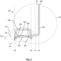
- FIG. 1 schematically represents a device 10 for drying and/or washing laundry, such as a tumble dryer, that is to say a household appliance designed to dry laundry by stirring it and subjecting it to a flow of hot air.
- the device 10 can be intended for particular or professional use
- the envelope 12 includes several facade panels 12a, 12b, some of which are removable.
- a device 10 of this type may include a top or front loading hatch 19.
- the device includes front panels, 4 in number (front, rear and side), at least some of which are removable for access, after disassembly and removal of at least least one of these panels, inside the envelope and the device.
- the device includes a front loading hatch, in the form of a porthole for example, the device includes front panels of which at least one side panel is removable for the same reason.
- the drum 14 defines any washing and/or drying volume which is adapted to its use (individual or professional).
- the device 10 comprises other elements such as in particular an electronic member 22 for monitoring and controlling the various electrical equipment of the device, a condenser or a pipe 23 for evacuating hot air loaded with humidity, etc. .
- the motor 16 includes an output shaft (not visible) which rotates the drum 14 around its axis 15 via a belt 24.
- the belt 24 extends around the drum 14 and the shaft. output of the motor 16, or of a pulley driven by this shaft, and extends generally in a substantially horizontal plane P1.
- the plane P1 is parallel to the side facade panels 12a of the device 10.
- the axis of rotation of the drum 14 is also horizontal and perpendicular to these panels 12a.
- the plane P1 would extend parallel to the rear panel of the device and the axis of rotation of the drum would be perpendicular to this rear panel. .
- the heating system 18 can be of any type and is for example of the heating resistance type, gas burner type, etc.
- the system 18 can be located under the drum 14 or on one side of the drum 14.
- the fire extinguishing device 20 is specifically designed to be integrated into the appliance 10 and comprises a pipe 26 of elongated shape and closed at its two longitudinal ends.
- the ends of the pipe 26 can be closed by plugs attached and fixed to the pipe, for example by gluing or welding. Alternatively, the ends of the pipe 26 could be directly closed by deformation and welding of its material.
- the pipe 26 comprises a fusible thermoplastic wall delimiting an internal space 28 in which a fire extinguishing fluid 29 is stored, possibly under pressure (cf. figure 4 ).
- This wall has, for example, a general circular shape in section.
- the wall of the pipe in whole or in part, could have another shape in section, for example square, rectangular, oval, etc.
- At least one of the ends of the pipe 26 could be equipped with a valve for filling the pipe with extinguishing fluid 29, as described in the application FR-A1-3 088 215 .
- the extinguishing fluid 29 is configured to be released by melting of the wall of the pipe under the effect of the heat provided by a fire or start of fire,
- the pipe 26 is thermoformed to impose a particular shape on it in the free state without constraint corresponding to its mounting position inside the envelope 12.
- the material of the pipe will be described in more detail in the following with reference to there Figure 4 .
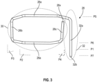
- the device 20 essentially comprises two parts better visible to the figure 2 And 3 , namely a first part in the form of a cradle 30 which extends between the drum 14 and the motor 16, and a second part 32 which extends on the side of one of the removable panels, here the front panel 12b.
- the first part is formed by a first portion of the pipe 26 which forms a loop delimiting the periphery of the cradle 30, and the second part is formed by a second portion of the pipe.
- the device 20 is configured to be mounted in the envelope 12 by dismantling and removing one of the removable facade panels, namely the front panel 12b in the example shown.
- the second portion 32 of the pipe 26 is located on the side of the panel 12b to facilitate the installation and fixing of the device 20 in the device.
- the cradle 30 extends from this panel 12b to the opposite front panel, here the rear panel.
- P3 comprises a rectilinear horizontal segment 36b which is located above the segments 26a of the intermediate plane, and which is parallel to a rectilinear horizontal segment 26c of the second plane P4.
- the second portion 32 of the pipe has a general L shape. It comprises a rectilinear horizontal segment 32a running along the segment 26c of the second plane P3. This second portion 32 further comprises a vertical rectilinear segment 32b.
- the segments 26a, 32b extend respectively in vertical planes P5, P6 and P7 parallel to each other and to the aforementioned plane P1.
- P1 is here located between P6 and P7.
- the cradle 30 has a width measured in the plane P2, between the segments 26a, which is less than the width of the second portion 32.
- the width of this portion 32 corresponds substantially to the length of the segment 32a of this portion.
- the pipe 26 can be fixed in two places on an element of the device 10, for example in zone Z1 on the inside of a facade panel of the envelope 12, and in zone Z2 on a casing made of material plastic located inside the envelope (for example that surrounding the motor 16 or a fan). Fixation can be done via plastic organs.
- One of these ends 26x of the pipe 26 is preferably equipped with a pressure sensor 34 which is configured to measure the pressure of the fluid 29 and which is connected to the control member 22 of the device 10.
- the member 22 is configured to put the device 10 in out-of-service mode when the pressure sensor 34 emits a signal corresponding to a pressure of the fluid 29 lower than a predetermined threshold.
- the member 22 can also be configured to emit a signal to a portable electronic device such as a smartphone-type mobile telephone, in order to warn the user or owner of the device in the event of a malfunction of the device. this last.
- the pipe 14 could be equipped with a sensor for measuring parameters other than pressure, such as temperature for example.
- the wall of the pipe 26 can be of the single-layer or multi-layer type. It can for example comprise two layers, respectively internal and external.
- the internal layer can be made of a material with low permeability compared to the extinguishing fluid 29, that is to say with a lower permeability or equal to 1 cm 3 .25 ⁇ m/m 2 .atm.24h. It is for example made of fluorinated thermoplastic or EVOH material.
- the outer layer is made of a polyamide thermoplastic material, which generally has a permeability greater than that of the inner layer, and for example greater than or equal to 1 cm 3 .25 ⁇ m/m 2 .atm.24h.
- the low permeability layer is located inside the higher permeability layer. Indeed, otherwise, there would be a risk of gas migrating through the internal layer with higher permeability and of stagnation of this gas at the interface between the two layers, likely to lead to delamination of the layers.
- a single-layer pipe should have a significant thickness of layer with low permeability. In the context of a two-layer or multi-layer pipe, this resistance is ensured by the layer(s) with higher permeability, and the layer with low permeability can have a relatively small thickness sufficient to ensure the desired impermeability function.
- the layer could be placed between two layers. This configuration would improve the mechanical strength of the layer during the pipe shaping stage (and thus avoid any risk of tearing of this layer), while guaranteeing optimal sealing of the pipe.
- At least one has a fuse property under the effect of the heat generated by a fire or the start of a fire, and in particular under the effect of a temperature greater than or equal to 70°C, or even 120°C.
- the two layers have such a fuse property.
- the pipe 26 has an external diameter of between 10 and 30 mm, and preferably between 10 and 20mm.
- the wall has a thickness of between 1 and 3mm, and preferably between 1 and 2mm.
- the pipe 26 has for example a length of between 1 and 5m
- the extinguishing fluid can be stored in the aforementioned space or cavity at a pressure greater than 1 bar and which can reach 10 bars, 20 bars, or even 30 bars.
- the extinguishing fluid preferably does not include HFC gas of the R236Fa type because this gas has a very high GWP or GWP of around 9400.
- the extinguishing fluid preferably has a GWP or GWP less than or equal to 5000.
- the fluid may comprise at least one HFC gas and/or C 6 F 12 O, and/or CO 2 .
- HFC gases that can be used, R227ea and R125 gases are preferred because they have a GWP or GWP of around 3400-3500.
- the DuPont ® company for example, markets gases of this type under the names FE-25 and FM-200.
- CO 2 is advantageous because it has a GWP or GWP of 1.
- C 6 F 12 O is also advantageous because it has a GWP or GWP of 1.
- the company 3M in particular markets this type of gas under the name Novec ® 1230 (FK-5-1-12).
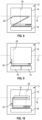
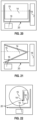
- THE figures 5 to 25 illustrate different variants illustrating several configurations for the device 10 and several possible installations and conformations for the device 20 and the pipe 16.
- the axis 15 of rotation of the drum 14 extends in the plane of the drawings. This axis is horizontal to figures 5 to 10 , 17 to 21 , and vertical to the Figure 25 . In the figures 11 to 16 , And 22 to 24 , this axis 15 is perpendicular to the plane of the drawings.
- the motor 16 and the heating system 18 can have different dimensions and positions in the envelope of the device 10. This is also the case for the belt 24.
- each of the parts of the pipe 14 can be adapted according to the dimensions and positions of the motor 16, and/or the system 18 and/or the belt 24.
- the device 20 may comprise several pipes 26 or a pipe 26 formed of several portions, segments or sections which are consecutive or disjointed from each other.
- the present invention also relates to a kit which comprises a device 20 as described in the above as well as fixings, such as the aforementioned plastic members, to allow the mounting and fixing of the device 20 and in particular of its pipe 26 in a device 10.
- This kit can therefore be considered as a conversion kit for a new or old device in order to equip it with an autonomous fire extinguishing device.
Landscapes
- Engineering & Computer Science (AREA)
- Textile Engineering (AREA)
- Health & Medical Sciences (AREA)
- Public Health (AREA)
- Business, Economics & Management (AREA)
- Emergency Management (AREA)
- Detail Structures Of Washing Machines And Dryers (AREA)
- Main Body Construction Of Washing Machines And Laundry Dryers (AREA)
- Accessory Of Washing/Drying Machine, Commercial Washing/Drying Machine, Other Washing/Drying Machine (AREA)
Claims (15)
- Einrichtung (10) zum Trocknen und/oder Waschen von Wäsche, umfassend:- ein Außengehäuse (12), das von allgemein quaderförmiger Form ist und mindestens eine erste abnehmbare Verkleidungsplatte (12b) umfasst,- eine Trommel (14), die sich in dem Gehäuse (12) befindet und um eine Achse (15) drehbeweglich ist, wobei diese Trommel einen inneren Hohlraum (17) umfasst, der so konfiguriert ist, dass er Wäsche aufnehmen kann,- einen Motor (16) zum Drehantrieb der Trommel (14) um ihre Achse (15), wobei sich dieser Motor im Gehäuse (12) unter der Trommel (14) befindet, und- ein System (18) zum Heizen und Erzeugen eines Heißluftstroms durch den Hohlraum (17), wobei sich dieses System im Gehäuse (12) befindet, dadurch gekennzeichnet, dass sie weiter eine autonome Vorrichtung (20) zum Löschen von Feuer umfasst, wobei diese Vorrichtung umfasst:- mindestens ein Rohr (26), das von länglicher Form und an seinen zwei Längsenden (26x) geschlossen ist, wobei dieses Rohr eine schmelzbare thermoplastische Wand umfasst, die einen inneren Raum begrenzt, wobei dieses Rohr thermogeformt ist, um ihm im freien spannungsfreien Zustand eine besondere Form zu verleihen, die seiner Montageposition im Inneren des Gehäuses (12) entspricht, und- ein Löschfluid (29) im Inneren des Raums, wobei dieses Löschfluid so konfiguriert ist, dass es durch Schmelzen der Wand des Rohres (26) unter der Wirkung der von einem Feuer oder dem Ausbruch eines Feuers eingetragenen Hitze freigesetzt wird,und dadurch, dass die Vorrichtung (20) so konfiguriert ist, dass sie durch Abbauen und Entfernen der ersten Verkleidungsplatte (12b) im Gehäuse (12) montiert werden kann, wobei die Vorrichtung (20) zwei Teile, nämlich einen ersten wiegenförmigen Teil (30), der sich zwischen der Trommel (14) und dem Motor (16) von der ersten Verkleidungsplatte (12b) bis zu einer der ersten Verkleidungsplatte gegenüberliegenden Verkleidungsplatte des Gehäuses erstreckt, und einen zweiten Teil (32) umfasst, der sich auf der Seite der ersten Verkleidungsplatte (12b) erstreckt, wobei der erste Teil von einem ersten Abschnitt des Rohres (26) gebildet wird, der eine Schleife bildet, die den Umfang der Wiege (30) begrenzt, und der zweite Teil von einem zweiten Abschnitt des Rohres (26) gebildet wird.
- Einrichtung (10) nach Anspruch 1, wobei sich der erste wiegenförmige Teil (30) in mindestens zwei sich schneidenden Ebenen (P2, P3, P4) erstreckt.
- Einrichtung (10) nach Anspruch 2, wobei sich der erste wiegenförmige Teil (30) in drei sich schneidenden Ebenen erstreckt, nämlich:- einer horizontalen Zwischenebene (P2), in der sich gerade und parallele Segmente (26a) des Rohres befinden,- einer ersten geneigten Ebene (P3), die sich auf der Seite der gegenüberliegenden Verkleidungsplatte befindet und sich von der Zwischenebene (P2) nach oben erstreckt, und- einer zweiten geneigten Ebene (P4), die sich auf der Seite der ersten Verkleidungsplatte (12b) befindet und sich von der Zwischenebene (P2) nach oben erstreckt.
- Einrichtung (10) nach Anspruch 3, wobei die erste geneigte Ebene (P3) ein horizontales gerades Segment (26b) umfasst, das sich über den geraden Segmenten (26a) der Zwischenebene (P2) befindet und das zu einem horizontalen geraden Segment (26c) der zweiten Ebene (P3) parallel ist.
- Einrichtung (10) nach einem der vorstehenden Ansprüche, wobei der zweite Abschnitt (32) des Rohres (26) eine allgemeine L-Form aufweist.
- Einrichtung (10) nach Anspruch 5 in Abhängigkeit von Anspruch 4, wobei der zweite Abschnitt (32) des Rohres (26) ein horizontales gerades Segment (32a) umfasst, das entlang des horizontalen geraden Segments (26c) der zweiten Ebene (P3) verläuft.
- Einrichtung (10) nach einem der vorstehenden Ansprüche, wobei der zweite Abschnitt (32) des Rohres (26) ein vertikales gerades Segment (32b) umfasst.
- Einrichtung (10) nach einem der vorstehenden Ansprüche, wobei eines der Längsenden (26x) des Rohres (26) mit mindestens einem Sensor (34) ausgestattet ist, der mit einem Steuerorgan (22) verbunden ist.
- Einrichtung (10) nach Anspruch 8, wobei das Organ (22) so konfiguriert ist, dass es die Einrichtung außer Betrieb setzt, wenn der Sensor (34) ein bestimmtes Signal ausgibt.
- Einrichtung (10) nach Anspruch 8 oder 9, wobei der Sensor (34) ein Sensor für Druck, Temperatur oder einen anderen Parameter ist.
- Einrichtung (10) nach einem der vorstehenden Ansprüche, wobei das Organ (22) so konfiguriert ist, dass es ein Signal an eine elektronische Vorrichtung, ein IT-Netzwerk oder eine IT-Datenbank ausgibt.
- Einrichtung (10) nach einem der vorstehenden Ansprüche, wobei sie weiter einen Antriebsriemen (24) umfasst, der um die Trommel (14) und eine Welle des Motors (16) montiert ist, wobei sich der erste Teil der Vorrichtung (20) zwischen dem Riemen (24) und einer Verkleidungsplatte (12b) des Gehäuses (12) erstreckt.
- Einrichtung (10) nach einem der vorstehenden Ansprüche, wobei das Rohr (26) eine Länge im Bereich zwischen 1 und 5 m und einen Durchmesser im Bereich zwischen 10 und 30 mm aufweist.
- Einrichtung (10) nach einem der vorstehenden Ansprüche, wobei sich das System (18) zum Heizen und Erzeugen eines Heißluftstroms unter der Trommel (14) oder an einer Seite der Trommel befindet.
- Bausatz für eine Einrichtung (10) nach einem der vorstehenden Ansprüche, dadurch gekennzeichnet, dass er umfasst:- die autonome Vorrichtung (20) zum Löschen von Feuer, wobei diese Vorrichtung umfasst:- mindestens ein Rohr (26), das von länglicher Form und an seinen zwei Längsenden (26x) geschlossen ist, wobei dieses Rohr eine schmelzbare thermoplastische Wand umfasst, die einen inneren Raum begrenzt, wobei dieses Rohr thermogeformt ist, um ihm im freien spannungsfreien Zustand eine besondere Form zu verleihen, die seiner Montageposition im Inneren des Gehäuses (12) entspricht, und- ein Löschfluid (29) im Inneren des Raums, wobei dieses Löschfluid so konfiguriert ist, dass es durch Schmelzen der Wand des Rohres (26) unter der Wirkung der von einem Feuer oder dem Ausbruch eines Feuers eingetragenen Hitze freigesetzt wird, wobei die Vorrichtung (20) so konfiguriert ist, dass sie durch Abbauen und Entfernen der ersten Verkleidungsplatte (12b) im Gehäuse (12) der Einrichtung montiert werden kann, wobei die Vorrichtung (20) zwei Teile, nämlich einen ersten wiegenförmigen Teil (30), der sich zwischen der Trommel (14) und dem Motor (16) von der ersten Verkleidungsplatte (12b) bis zu einer der ersten Verkleidungsplatte gegenüberliegenden Verkleidungsplatte des Gehäuses erstreckt, und einen zweiten Teil (32) umfasst, der sich auf der Seite der ersten Verkleidungsplatte (12b) erstreckt, wobei der erste Teil von einem ersten Abschnitt des Rohres (26) gebildet wird, der eine Schleife bildet, die den Umfang der Wiege (30) begrenzt, und der zweite Teil von einem zweiten Abschnitt des Rohres (26) gebildet wird, und- Befestigungen der Vorrichtung (20) an der Einrichtung.
Applications Claiming Priority (2)
| Application Number | Priority Date | Filing Date | Title |
|---|---|---|---|
| FR2005219A FR3110608B1 (fr) | 2020-05-20 | 2020-05-20 | Appareil de sechage et/ou de lavage de linge equipe d’un système autonome d’extinction de feu |
| PCT/EP2021/058936 WO2021233605A1 (fr) | 2020-05-20 | 2021-04-06 | Appareil de sechage et/ou de lavage de linge equipe d'un systeme autonome d'extinction de feu |
Publications (2)
| Publication Number | Publication Date |
|---|---|
| EP4153805A1 EP4153805A1 (de) | 2023-03-29 |
| EP4153805B1 true EP4153805B1 (de) | 2024-05-01 |
Family
ID=72178739
Family Applications (1)
| Application Number | Title | Priority Date | Filing Date |
|---|---|---|---|
| EP21717051.3A Active EP4153805B1 (de) | 2020-05-20 | 2021-04-06 | Gerät zum trocknen und/oder waschen von wäsche mit einem autonomen feuerlöschsystem |
Country Status (8)
| Country | Link |
|---|---|
| US (1) | US12331447B2 (de) |
| EP (1) | EP4153805B1 (de) |
| CN (1) | CN115768938A (de) |
| ES (1) | ES2980702T3 (de) |
| FR (1) | FR3110608B1 (de) |
| MX (1) | MX2022014323A (de) |
| PL (1) | PL4153805T3 (de) |
| WO (1) | WO2021233605A1 (de) |
Families Citing this family (1)
| Publication number | Priority date | Publication date | Assignee | Title |
|---|---|---|---|---|
| FR3132529B1 (fr) | 2022-02-10 | 2025-06-27 | Hutchinson | Appareil de sechage et/ou de lavage de linge equipe d’un dispositif autonome d’extinction de feu |
Family Cites Families (10)
| Publication number | Priority date | Publication date | Assignee | Title |
|---|---|---|---|---|
| US3770061A (en) * | 1971-11-03 | 1973-11-06 | T Hall | Air scrubber apparatus with improved fire extinguishing means |
| ES2006865A6 (es) | 1987-04-24 | 1989-05-16 | Faini Spa | Dispositivo de proteccion contra el incendio de aparatos electricos con partes inflamables. |
| SE532446C2 (sv) * | 2007-04-12 | 2010-01-19 | Electrolux Ab | Brandskyddssystem för en torkmaskin för kläder |
| DE102007061521A1 (de) * | 2007-12-20 | 2009-06-25 | BSH Bosch und Siemens Hausgeräte GmbH | Wäschetrocknungsgerät und Verfahren zum Betreiben eines Wäschetrocknungsgeräts |
| EP2527528B1 (de) * | 2011-05-27 | 2014-12-10 | Electrolux Home Products Corporation N.V. | Wäschetrockner mit Drehtrommel |
| DE102011087607B4 (de) * | 2011-12-01 | 2016-11-24 | BSH Hausgeräte GmbH | Wäschetrockner mit einer Feuerlöscheinrichtung |
| DE102012200075B3 (de) * | 2012-01-04 | 2013-02-21 | BSH Bosch und Siemens Hausgeräte GmbH | Wäschetrockner mit selbsttätigem Feuerlöschsystem |
| JP6655565B2 (ja) * | 2017-02-06 | 2020-02-26 | 東京瓦斯株式会社 | 衣類乾燥装置 |
| CN106955446B (zh) * | 2017-04-11 | 2018-05-25 | 黄河科技学院 | 一种用于建筑施工的消防喷淋装置 |
| FR3088215B1 (fr) * | 2018-11-12 | 2023-05-12 | Hutchinson | Tuyau extincteur et son procede de fabrication |
-
2020
- 2020-05-20 FR FR2005219A patent/FR3110608B1/fr active Active
-
2021
- 2021-04-06 MX MX2022014323A patent/MX2022014323A/es unknown
- 2021-04-06 CN CN202180042415.3A patent/CN115768938A/zh active Pending
- 2021-04-06 WO PCT/EP2021/058936 patent/WO2021233605A1/fr not_active Ceased
- 2021-04-06 US US17/999,040 patent/US12331447B2/en active Active
- 2021-04-06 ES ES21717051T patent/ES2980702T3/es active Active
- 2021-04-06 PL PL21717051.3T patent/PL4153805T3/pl unknown
- 2021-04-06 EP EP21717051.3A patent/EP4153805B1/de active Active
Also Published As
| Publication number | Publication date |
|---|---|
| ES2980702T3 (es) | 2024-10-02 |
| CN115768938A (zh) | 2023-03-07 |
| MX2022014323A (es) | 2023-02-27 |
| US20230220603A1 (en) | 2023-07-13 |
| PL4153805T3 (pl) | 2024-07-29 |
| US12331447B2 (en) | 2025-06-17 |
| EP4153805A1 (de) | 2023-03-29 |
| FR3110608B1 (fr) | 2022-04-15 |
| FR3110608A1 (fr) | 2021-11-26 |
| WO2021233605A1 (fr) | 2021-11-25 |
Similar Documents
| Publication | Publication Date | Title |
|---|---|---|
| EP1251257B1 (de) | Lufteinlasshaube eines Strahltriebwerkes mit Enteisungsvorrichtung | |
| EP0918149B1 (de) | Schutzeinrichtung für den mit einem Enteisungssystem versehenen Lufteinlauf eines Strahltriebwerks | |
| EP4476394A1 (de) | Vorrichtung zum trocknen und/oder waschen von wäsche mit einer autonomen feuerlöschvorrichtung | |
| EP4153805B1 (de) | Gerät zum trocknen und/oder waschen von wäsche mit einem autonomen feuerlöschsystem | |
| EP3880314B1 (de) | Feuerlöschschlauch für ein batteriefach oder ein kraftfahrzeug | |
| WO2004036121A1 (fr) | Echangeur de chaleur a condensation, a enveloppe plastique | |
| WO2015079166A1 (fr) | Ensemble de combustion a accès facilite des cannes de prévaporisation | |
| EP4063759B1 (de) | System zur wassererhitzung | |
| EP2497385B1 (de) | Haartrockner ausgestattet mit abnehmbarem Schalldämpfer | |
| FR2805591A1 (fr) | Dispositif thermostatique a deux regimes de regulation commandes selectivement | |
| EP3342466B1 (de) | Brandschutzvorrichtung zur durchführung durch eine wand | |
| EP4306181A1 (de) | Kraftfahrzeug mit einem batteriepack mit feuerlöschvorrichtung | |
| FR2695473A1 (fr) | Dispositif de mesure pour déterminer le trouble des gaz. | |
| LU88109A1 (fr) | Dispositif incorpore a un miroir pour eviter la formation de buee | |
| FR3078384A1 (fr) | Chambre de combustion a fond de chambre double | |
| WO2023118374A1 (fr) | Unité de stockage de fluide cryogénique | |
| FR3106368A1 (fr) | Pot catalytique de vehicule destine a reduire les emissions de polluants | |
| WO2024231609A1 (fr) | Elément de stockage pour un équipement électrique | |
| FR2616716A1 (fr) | Rechauffeur calorifuge de gas-oil | |
| FR2816394A1 (fr) | Appareil de chauffage domestique par rayonnement et par convection | |
| FR2869363A1 (fr) | Joint dynamique haute temperature pour statoreacteur a combustion supersonique a geometrie variable | |
| FR2661975A1 (fr) | Dispositif pour la recuperation et le transfert de la chaleur accumulee dans le plenum des cheminees a foyer ouvert ou ferme. | |
| EP4452757A1 (de) | Integration eines feuerlöschers in eine feuer-zone einer turbomaschine | |
| FR2944338A1 (fr) | Crepine chauffante de systeme d'injection de carburant pour turbomoteur d'aeronef | |
| FR3115334A1 (fr) | Pompe pour fluide cryogénique |
Legal Events
| Date | Code | Title | Description |
|---|---|---|---|
| STAA | Information on the status of an ep patent application or granted ep patent |
Free format text: STATUS: UNKNOWN |
|
| STAA | Information on the status of an ep patent application or granted ep patent |
Free format text: STATUS: THE INTERNATIONAL PUBLICATION HAS BEEN MADE |
|
| PUAI | Public reference made under article 153(3) epc to a published international application that has entered the european phase |
Free format text: ORIGINAL CODE: 0009012 |
|
| STAA | Information on the status of an ep patent application or granted ep patent |
Free format text: STATUS: REQUEST FOR EXAMINATION WAS MADE |
|
| 17P | Request for examination filed |
Effective date: 20221208 |
|
| AK | Designated contracting states |
Kind code of ref document: A1 Designated state(s): AL AT BE BG CH CY CZ DE DK EE ES FI FR GB GR HR HU IE IS IT LI LT LU LV MC MK MT NL NO PL PT RO RS SE SI SK SM TR |
|
| DAV | Request for validation of the european patent (deleted) | ||
| DAX | Request for extension of the european patent (deleted) | ||
| GRAP | Despatch of communication of intention to grant a patent |
Free format text: ORIGINAL CODE: EPIDOSNIGR1 |
|
| STAA | Information on the status of an ep patent application or granted ep patent |
Free format text: STATUS: GRANT OF PATENT IS INTENDED |
|
| INTG | Intention to grant announced |
Effective date: 20240122 |
|
| GRAS | Grant fee paid |
Free format text: ORIGINAL CODE: EPIDOSNIGR3 |
|
| GRAA | (expected) grant |
Free format text: ORIGINAL CODE: 0009210 |
|
| STAA | Information on the status of an ep patent application or granted ep patent |
Free format text: STATUS: THE PATENT HAS BEEN GRANTED |
|
| AK | Designated contracting states |
Kind code of ref document: B1 Designated state(s): AL AT BE BG CH CY CZ DE DK EE ES FI FR GB GR HR HU IE IS IT LI LT LU LV MC MK MT NL NO PL PT RO RS SE SI SK SM TR |
|
| REG | Reference to a national code |
Ref country code: GB Ref legal event code: FG4D Free format text: NOT ENGLISH |
|
| REG | Reference to a national code |
Ref country code: CH Ref legal event code: EP |
|
| REG | Reference to a national code |
Ref country code: IE Ref legal event code: FG4D Free format text: LANGUAGE OF EP DOCUMENT: FRENCH |
|
| REG | Reference to a national code |
Ref country code: DE Ref legal event code: R096 Ref document number: 602021012708 Country of ref document: DE |
|
| REG | Reference to a national code |
Ref country code: SE Ref legal event code: TRGR |
|
| REG | Reference to a national code |
Ref country code: LT Ref legal event code: MG9D |
|
| REG | Reference to a national code |
Ref country code: SK Ref legal event code: T3 Ref document number: E 44419 Country of ref document: SK |
|
| REG | Reference to a national code |
Ref country code: NL Ref legal event code: MP Effective date: 20240501 |
|
| REG | Reference to a national code |
Ref country code: ES Ref legal event code: FG2A Ref document number: 2980702 Country of ref document: ES Kind code of ref document: T3 Effective date: 20241002 |
|
| PG25 | Lapsed in a contracting state [announced via postgrant information from national office to epo] |
Ref country code: IS Free format text: LAPSE BECAUSE OF FAILURE TO SUBMIT A TRANSLATION OF THE DESCRIPTION OR TO PAY THE FEE WITHIN THE PRESCRIBED TIME-LIMIT Effective date: 20240901 |
|
| PG25 | Lapsed in a contracting state [announced via postgrant information from national office to epo] |
Ref country code: BG Free format text: LAPSE BECAUSE OF FAILURE TO SUBMIT A TRANSLATION OF THE DESCRIPTION OR TO PAY THE FEE WITHIN THE PRESCRIBED TIME-LIMIT Effective date: 20240501 |
|
| PG25 | Lapsed in a contracting state [announced via postgrant information from national office to epo] |
Ref country code: FI Free format text: LAPSE BECAUSE OF FAILURE TO SUBMIT A TRANSLATION OF THE DESCRIPTION OR TO PAY THE FEE WITHIN THE PRESCRIBED TIME-LIMIT Effective date: 20240501 Ref country code: HR Free format text: LAPSE BECAUSE OF FAILURE TO SUBMIT A TRANSLATION OF THE DESCRIPTION OR TO PAY THE FEE WITHIN THE PRESCRIBED TIME-LIMIT Effective date: 20240501 |
|
| PG25 | Lapsed in a contracting state [announced via postgrant information from national office to epo] |
Ref country code: GR Free format text: LAPSE BECAUSE OF FAILURE TO SUBMIT A TRANSLATION OF THE DESCRIPTION OR TO PAY THE FEE WITHIN THE PRESCRIBED TIME-LIMIT Effective date: 20240802 |
|
| PG25 | Lapsed in a contracting state [announced via postgrant information from national office to epo] |
Ref country code: PT Free format text: LAPSE BECAUSE OF FAILURE TO SUBMIT A TRANSLATION OF THE DESCRIPTION OR TO PAY THE FEE WITHIN THE PRESCRIBED TIME-LIMIT Effective date: 20240902 |
|
| REG | Reference to a national code |
Ref country code: AT Ref legal event code: MK05 Ref document number: 1682474 Country of ref document: AT Kind code of ref document: T Effective date: 20240501 |
|
| PG25 | Lapsed in a contracting state [announced via postgrant information from national office to epo] |
Ref country code: NL Free format text: LAPSE BECAUSE OF FAILURE TO SUBMIT A TRANSLATION OF THE DESCRIPTION OR TO PAY THE FEE WITHIN THE PRESCRIBED TIME-LIMIT Effective date: 20240501 |
|
| PG25 | Lapsed in a contracting state [announced via postgrant information from national office to epo] |
Ref country code: AT Free format text: LAPSE BECAUSE OF FAILURE TO SUBMIT A TRANSLATION OF THE DESCRIPTION OR TO PAY THE FEE WITHIN THE PRESCRIBED TIME-LIMIT Effective date: 20240501 |
|
| PG25 | Lapsed in a contracting state [announced via postgrant information from national office to epo] |
Ref country code: LV Free format text: LAPSE BECAUSE OF FAILURE TO SUBMIT A TRANSLATION OF THE DESCRIPTION OR TO PAY THE FEE WITHIN THE PRESCRIBED TIME-LIMIT Effective date: 20240501 |
|
| PG25 | Lapsed in a contracting state [announced via postgrant information from national office to epo] |
Ref country code: PT Free format text: LAPSE BECAUSE OF FAILURE TO SUBMIT A TRANSLATION OF THE DESCRIPTION OR TO PAY THE FEE WITHIN THE PRESCRIBED TIME-LIMIT Effective date: 20240902 Ref country code: NO Free format text: LAPSE BECAUSE OF FAILURE TO SUBMIT A TRANSLATION OF THE DESCRIPTION OR TO PAY THE FEE WITHIN THE PRESCRIBED TIME-LIMIT Effective date: 20240801 Ref country code: NL Free format text: LAPSE BECAUSE OF FAILURE TO SUBMIT A TRANSLATION OF THE DESCRIPTION OR TO PAY THE FEE WITHIN THE PRESCRIBED TIME-LIMIT Effective date: 20240501 Ref country code: LV Free format text: LAPSE BECAUSE OF FAILURE TO SUBMIT A TRANSLATION OF THE DESCRIPTION OR TO PAY THE FEE WITHIN THE PRESCRIBED TIME-LIMIT Effective date: 20240501 Ref country code: IS Free format text: LAPSE BECAUSE OF FAILURE TO SUBMIT A TRANSLATION OF THE DESCRIPTION OR TO PAY THE FEE WITHIN THE PRESCRIBED TIME-LIMIT Effective date: 20240901 Ref country code: HR Free format text: LAPSE BECAUSE OF FAILURE TO SUBMIT A TRANSLATION OF THE DESCRIPTION OR TO PAY THE FEE WITHIN THE PRESCRIBED TIME-LIMIT Effective date: 20240501 Ref country code: GR Free format text: LAPSE BECAUSE OF FAILURE TO SUBMIT A TRANSLATION OF THE DESCRIPTION OR TO PAY THE FEE WITHIN THE PRESCRIBED TIME-LIMIT Effective date: 20240802 Ref country code: FI Free format text: LAPSE BECAUSE OF FAILURE TO SUBMIT A TRANSLATION OF THE DESCRIPTION OR TO PAY THE FEE WITHIN THE PRESCRIBED TIME-LIMIT Effective date: 20240501 Ref country code: BG Free format text: LAPSE BECAUSE OF FAILURE TO SUBMIT A TRANSLATION OF THE DESCRIPTION OR TO PAY THE FEE WITHIN THE PRESCRIBED TIME-LIMIT Effective date: 20240501 Ref country code: AT Free format text: LAPSE BECAUSE OF FAILURE TO SUBMIT A TRANSLATION OF THE DESCRIPTION OR TO PAY THE FEE WITHIN THE PRESCRIBED TIME-LIMIT Effective date: 20240501 Ref country code: RS Free format text: LAPSE BECAUSE OF FAILURE TO SUBMIT A TRANSLATION OF THE DESCRIPTION OR TO PAY THE FEE WITHIN THE PRESCRIBED TIME-LIMIT Effective date: 20240801 |
|
| P01 | Opt-out of the competence of the unified patent court (upc) registered |
Free format text: CASE NUMBER: APP_58743/2024 Effective date: 20241028 |
|
| PG25 | Lapsed in a contracting state [announced via postgrant information from national office to epo] |
Ref country code: DK Free format text: LAPSE BECAUSE OF FAILURE TO SUBMIT A TRANSLATION OF THE DESCRIPTION OR TO PAY THE FEE WITHIN THE PRESCRIBED TIME-LIMIT Effective date: 20240501 |
|
| PG25 | Lapsed in a contracting state [announced via postgrant information from national office to epo] |
Ref country code: EE Free format text: LAPSE BECAUSE OF FAILURE TO SUBMIT A TRANSLATION OF THE DESCRIPTION OR TO PAY THE FEE WITHIN THE PRESCRIBED TIME-LIMIT Effective date: 20240501 |
|
| PG25 | Lapsed in a contracting state [announced via postgrant information from national office to epo] |
Ref country code: RO Free format text: LAPSE BECAUSE OF FAILURE TO SUBMIT A TRANSLATION OF THE DESCRIPTION OR TO PAY THE FEE WITHIN THE PRESCRIBED TIME-LIMIT Effective date: 20240501 |
|
| PG25 | Lapsed in a contracting state [announced via postgrant information from national office to epo] |
Ref country code: SM Free format text: LAPSE BECAUSE OF FAILURE TO SUBMIT A TRANSLATION OF THE DESCRIPTION OR TO PAY THE FEE WITHIN THE PRESCRIBED TIME-LIMIT Effective date: 20240501 |
|
| PG25 | Lapsed in a contracting state [announced via postgrant information from national office to epo] |
Ref country code: SM Free format text: LAPSE BECAUSE OF FAILURE TO SUBMIT A TRANSLATION OF THE DESCRIPTION OR TO PAY THE FEE WITHIN THE PRESCRIBED TIME-LIMIT Effective date: 20240501 Ref country code: RO Free format text: LAPSE BECAUSE OF FAILURE TO SUBMIT A TRANSLATION OF THE DESCRIPTION OR TO PAY THE FEE WITHIN THE PRESCRIBED TIME-LIMIT Effective date: 20240501 Ref country code: EE Free format text: LAPSE BECAUSE OF FAILURE TO SUBMIT A TRANSLATION OF THE DESCRIPTION OR TO PAY THE FEE WITHIN THE PRESCRIBED TIME-LIMIT Effective date: 20240501 Ref country code: DK Free format text: LAPSE BECAUSE OF FAILURE TO SUBMIT A TRANSLATION OF THE DESCRIPTION OR TO PAY THE FEE WITHIN THE PRESCRIBED TIME-LIMIT Effective date: 20240501 |
|
| REG | Reference to a national code |
Ref country code: DE Ref legal event code: R097 Ref document number: 602021012708 Country of ref document: DE |
|
| PLBE | No opposition filed within time limit |
Free format text: ORIGINAL CODE: 0009261 |
|
| STAA | Information on the status of an ep patent application or granted ep patent |
Free format text: STATUS: NO OPPOSITION FILED WITHIN TIME LIMIT |
|
| 26N | No opposition filed |
Effective date: 20250204 |
|
| PG25 | Lapsed in a contracting state [announced via postgrant information from national office to epo] |
Ref country code: SI Free format text: LAPSE BECAUSE OF FAILURE TO SUBMIT A TRANSLATION OF THE DESCRIPTION OR TO PAY THE FEE WITHIN THE PRESCRIBED TIME-LIMIT Effective date: 20240501 |
|
| PGFP | Annual fee paid to national office [announced via postgrant information from national office to epo] |
Ref country code: PL Payment date: 20250328 Year of fee payment: 5 |
|
| PGFP | Annual fee paid to national office [announced via postgrant information from national office to epo] |
Ref country code: SK Payment date: 20250331 Year of fee payment: 5 |
|
| PGFP | Annual fee paid to national office [announced via postgrant information from national office to epo] |
Ref country code: DE Payment date: 20250422 Year of fee payment: 5 |
|
| PGFP | Annual fee paid to national office [announced via postgrant information from national office to epo] |
Ref country code: ES Payment date: 20250530 Year of fee payment: 5 |
|
| PGFP | Annual fee paid to national office [announced via postgrant information from national office to epo] |
Ref country code: BE Payment date: 20250418 Year of fee payment: 5 Ref country code: IT Payment date: 20250424 Year of fee payment: 5 |
|
| PGFP | Annual fee paid to national office [announced via postgrant information from national office to epo] |
Ref country code: FR Payment date: 20250425 Year of fee payment: 5 |
|
| PGFP | Annual fee paid to national office [announced via postgrant information from national office to epo] |
Ref country code: CH Payment date: 20250501 Year of fee payment: 5 |
|
| PGFP | Annual fee paid to national office [announced via postgrant information from national office to epo] |
Ref country code: TR Payment date: 20250402 Year of fee payment: 5 |
|
| PGFP | Annual fee paid to national office [announced via postgrant information from national office to epo] |
Ref country code: CZ Payment date: 20250401 Year of fee payment: 5 |
|
| PGFP | Annual fee paid to national office [announced via postgrant information from national office to epo] |
Ref country code: SE Payment date: 20250429 Year of fee payment: 5 |
|
| PG25 | Lapsed in a contracting state [announced via postgrant information from national office to epo] |
Ref country code: LU Free format text: LAPSE BECAUSE OF NON-PAYMENT OF DUE FEES Effective date: 20250406 |
|
| PG25 | Lapsed in a contracting state [announced via postgrant information from national office to epo] |
Ref country code: MC Free format text: LAPSE BECAUSE OF FAILURE TO SUBMIT A TRANSLATION OF THE DESCRIPTION OR TO PAY THE FEE WITHIN THE PRESCRIBED TIME-LIMIT Effective date: 20240501 |
|
| GBPC | Gb: european patent ceased through non-payment of renewal fee |
Effective date: 20250406 |
|
| PG25 | Lapsed in a contracting state [announced via postgrant information from national office to epo] |
Ref country code: GB Free format text: LAPSE BECAUSE OF NON-PAYMENT OF DUE FEES Effective date: 20250406 |
|
| PG25 | Lapsed in a contracting state [announced via postgrant information from national office to epo] |
Ref country code: IE Free format text: LAPSE BECAUSE OF NON-PAYMENT OF DUE FEES Effective date: 20250406 |