EP4153805B1 - Appliance for drying and/or washing laundry equipped with an autonomous fire extinguishing system - Google Patents
Appliance for drying and/or washing laundry equipped with an autonomous fire extinguishing system Download PDFInfo
- Publication number
- EP4153805B1 EP4153805B1 EP21717051.3A EP21717051A EP4153805B1 EP 4153805 B1 EP4153805 B1 EP 4153805B1 EP 21717051 A EP21717051 A EP 21717051A EP 4153805 B1 EP4153805 B1 EP 4153805B1
- Authority
- EP
- European Patent Office
- Prior art keywords
- pipe
- appliance
- drum
- face panel
- fire
- Prior art date
- Legal status (The legal status is an assumption and is not a legal conclusion. Google has not performed a legal analysis and makes no representation as to the accuracy of the status listed.)
- Active
Links
- 238000005406 washing Methods 0.000 title claims description 14
- 238000001035 drying Methods 0.000 title claims description 12
- 239000012530 fluid Substances 0.000 claims description 25
- 238000010438 heat treatment Methods 0.000 claims description 14
- 229920001169 thermoplastic Polymers 0.000 claims description 6
- 239000004416 thermosoftening plastic Substances 0.000 claims description 6
- 230000004927 fusion Effects 0.000 claims description 4
- 239000010410 layer Substances 0.000 description 21
- 241001417494 Sciaenidae Species 0.000 description 13
- 239000007789 gas Substances 0.000 description 11
- 239000000463 material Substances 0.000 description 10
- 230000035699 permeability Effects 0.000 description 10
- 230000008033 biological extinction Effects 0.000 description 6
- 238000009434 installation Methods 0.000 description 6
- 230000004907 flux Effects 0.000 description 5
- 230000008018 melting Effects 0.000 description 4
- 238000002844 melting Methods 0.000 description 4
- 238000011068 loading method Methods 0.000 description 3
- 238000012423 maintenance Methods 0.000 description 3
- 239000004033 plastic Substances 0.000 description 3
- 229920003023 plastic Polymers 0.000 description 3
- 239000002356 single layer Substances 0.000 description 3
- 238000003756 stirring Methods 0.000 description 3
- 238000012550 audit Methods 0.000 description 2
- 239000000428 dust Substances 0.000 description 2
- 230000010354 integration Effects 0.000 description 2
- 238000013021 overheating Methods 0.000 description 2
- 238000007493 shaping process Methods 0.000 description 2
- 239000000126 substance Substances 0.000 description 2
- 238000003856 thermoforming Methods 0.000 description 2
- 238000003466 welding Methods 0.000 description 2
- 229920000219 Ethylene vinyl alcohol Polymers 0.000 description 1
- 239000004952 Polyamide Substances 0.000 description 1
- 238000004026 adhesive bonding Methods 0.000 description 1
- 230000009172 bursting Effects 0.000 description 1
- 238000006243 chemical reaction Methods 0.000 description 1
- 239000012459 cleaning agent Substances 0.000 description 1
- 230000032798 delamination Effects 0.000 description 1
- 238000011161 development Methods 0.000 description 1
- 238000009826 distribution Methods 0.000 description 1
- UFRKOOWSQGXVKV-UHFFFAOYSA-N ethene;ethenol Chemical compound C=C.OC=C UFRKOOWSQGXVKV-UHFFFAOYSA-N 0.000 description 1
- 239000004715 ethylene vinyl alcohol Substances 0.000 description 1
- 238000011049 filling Methods 0.000 description 1
- 238000003780 insertion Methods 0.000 description 1
- 230000037431 insertion Effects 0.000 description 1
- 238000002955 isolation Methods 0.000 description 1
- 239000007788 liquid Substances 0.000 description 1
- 230000007257 malfunction Effects 0.000 description 1
- 238000007726 management method Methods 0.000 description 1
- 238000004519 manufacturing process Methods 0.000 description 1
- 238000012544 monitoring process Methods 0.000 description 1
- 210000000056 organ Anatomy 0.000 description 1
- 229920002647 polyamide Polymers 0.000 description 1
- 238000007789 sealing Methods 0.000 description 1
- 230000008054 signal transmission Effects 0.000 description 1
- 239000012815 thermoplastic material Substances 0.000 description 1
- XLYOFNOQVPJJNP-UHFFFAOYSA-N water Substances O XLYOFNOQVPJJNP-UHFFFAOYSA-N 0.000 description 1
Images


Classifications
-
- D—TEXTILES; PAPER
- D06—TREATMENT OF TEXTILES OR THE LIKE; LAUNDERING; FLEXIBLE MATERIALS NOT OTHERWISE PROVIDED FOR
- D06F—LAUNDERING, DRYING, IRONING, PRESSING OR FOLDING TEXTILE ARTICLES
- D06F37/00—Details specific to washing machines covered by groups D06F21/00 - D06F25/00
- D06F37/42—Safety arrangements, e.g. for stopping rotation of the receptacle upon opening of the casing door
-
- D—TEXTILES; PAPER
- D06—TREATMENT OF TEXTILES OR THE LIKE; LAUNDERING; FLEXIBLE MATERIALS NOT OTHERWISE PROVIDED FOR
- D06F—LAUNDERING, DRYING, IRONING, PRESSING OR FOLDING TEXTILE ARTICLES
- D06F33/00—Control of operations performed in washing machines or washer-dryers
- D06F33/50—Control of washer-dryers characterised by the purpose or target of the control
- D06F33/74—Responding to irregular working conditions, e.g. malfunctioning of pumps
-
- D—TEXTILES; PAPER
- D06—TREATMENT OF TEXTILES OR THE LIKE; LAUNDERING; FLEXIBLE MATERIALS NOT OTHERWISE PROVIDED FOR
- D06F—LAUNDERING, DRYING, IRONING, PRESSING OR FOLDING TEXTILE ARTICLES
- D06F58/00—Domestic laundry dryers
- D06F58/20—General details of domestic laundry dryers
-
- A—HUMAN NECESSITIES
- A62—LIFE-SAVING; FIRE-FIGHTING
- A62C—FIRE-FIGHTING
- A62C3/00—Fire prevention, containment or extinguishing specially adapted for particular objects or places
- A62C3/16—Fire prevention, containment or extinguishing specially adapted for particular objects or places in electrical installations, e.g. cableways
-
- D—TEXTILES; PAPER
- D06—TREATMENT OF TEXTILES OR THE LIKE; LAUNDERING; FLEXIBLE MATERIALS NOT OTHERWISE PROVIDED FOR
- D06F—LAUNDERING, DRYING, IRONING, PRESSING OR FOLDING TEXTILE ARTICLES
- D06F2103/00—Parameters monitored or detected for the control of domestic laundry washing machines, washer-dryers or laundry dryers
-
- D—TEXTILES; PAPER
- D06—TREATMENT OF TEXTILES OR THE LIKE; LAUNDERING; FLEXIBLE MATERIALS NOT OTHERWISE PROVIDED FOR
- D06F—LAUNDERING, DRYING, IRONING, PRESSING OR FOLDING TEXTILE ARTICLES
- D06F2105/00—Systems or parameters controlled or affected by the control systems of washing machines, washer-dryers or laundry dryers
- D06F2105/62—Stopping or disabling machine operation
-
- D—TEXTILES; PAPER
- D06—TREATMENT OF TEXTILES OR THE LIKE; LAUNDERING; FLEXIBLE MATERIALS NOT OTHERWISE PROVIDED FOR
- D06F—LAUNDERING, DRYING, IRONING, PRESSING OR FOLDING TEXTILE ARTICLES
- D06F58/00—Domestic laundry dryers
- D06F58/32—Control of operations performed in domestic laundry dryers
- D06F58/34—Control of operations performed in domestic laundry dryers characterised by the purpose or target of the control
- D06F58/50—Responding to irregular working conditions, e.g. malfunctioning of blowers
Definitions
- the present invention relates to a laundry drying and/or washing appliance equipped with an autonomous fire extinguishing or fire starting system.
- the patent application FR-A1-2 614 209 describes a fire-fighting device for electrical appliances containing flammable components and in particular for a washing machine or dryer.
- a laundry drying and/or washing appliance is a household appliance which comprises a rotating drum in which laundry is placed for washing with water and a cleaning agent, or damp laundry for drying by stirring. .
- the drum is generally rotated by a belt which is itself driven by an electric motor.
- a washing machine can have a dryer function. In both cases, the drum of the device can be passed through by a flow of hot air so as to facilitate the drying of the laundry when it is tossed.
- the heating and hot air flow generation system of the device may include a gas burner or an electric resistance for example.
- This household appliance is the cause of many domestic fires. Heating and stirring the laundry in the drum generates flammable dust which accumulates inside the appliance and which is likely to ignite, particularly when deposited on very hot parts of the appliance. device such as the engine or the heating system. A fire caused by the ignition of dust can cause a larger fire in the device, particularly by ignition of the drum drive belt.
- the patent application mentioned above proposes installing a tank in the form of a pressure bomb in a washing machine, this tank being connected to pipes that are normally closed and likely to rupture at a determined temperature threshold. These pipes extend to parts of the device which are subject to overheating or catching fire, such as electrical devices, resistances, the motor, flammable components, etc.
- the fire-fighting substance contained in the tank is at least slightly under pressure and the distribution pipes are made of a material intended to melt to ensure the rupture or opening of these pipes when the latter are licked by flames or when the temperature of their environment exceeds a predetermined threshold. In this way, as soon as overheating or flammability conditions arise which could give rise to a fire inside the device, the pipes break and automatically distribute the fire-fighting substance to immediately extinguish the possible development of a fire.
- the solution described in this patent application is, however, not entirely satisfactory because the fire extinguishing system formed by the tank and the pipes is complex and takes a long time to install in a household appliance. In fact, it includes several elements which must be installed and fixed one after the other and connected to each other in the device. These elements are located in several areas inside the device so that the installation of the system in the device can only be done during the manufacture of this device. Likewise, in the event of maintenance, it is necessary to dismantle several front panels of the device to access the system. The system described in this application cannot therefore easily be integrated into an existing device which would not have been originally designed to be equipped with this system.
- the state of the art also includes the document US-B2-9,885,142 .
- the present invention proposes a solution to at least part of the problems mentioned in the above, which is simple, effective and economical and allows both simple and rapid integration into the specific environment of a laundry drying and/or washing appliance.
- the pipe also has its two ends which are closed in a watertight manner.
- the pipe has an elongated shape and is made of a material facilitating on the one hand its shaping by heating (called thermoforming), before its assembly in the device, as well as allowing the release of the extinguishing fluid by melting and bursting.
- the pipe is arranged in two portions.
- a first portion of the pipe forms a cradle extending between the drum and the motor.
- a cradle generally has a rounded or hollow shape, which allows it to extend around the drum and conform to its shape.
- the pipe forms a loop which allows it to extend over the entire area between the motor and the drum, which is a critical area for the occurrence of fire, without risk of disrupting the operation of the device.
- the second portion of the pipe extends on the side of the removable facade panel and for example along part of the drum drive belt.
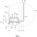
- FIG. 1 schematically represents a device 10 for drying and/or washing laundry, such as a tumble dryer, that is to say a household appliance designed to dry laundry by stirring it and subjecting it to a flow of hot air.
- the device 10 can be intended for particular or professional use
- the envelope 12 includes several facade panels 12a, 12b, some of which are removable.
- a device 10 of this type may include a top or front loading hatch 19.
- the device includes front panels, 4 in number (front, rear and side), at least some of which are removable for access, after disassembly and removal of at least least one of these panels, inside the envelope and the device.
- the device includes a front loading hatch, in the form of a porthole for example, the device includes front panels of which at least one side panel is removable for the same reason.
- the drum 14 defines any washing and/or drying volume which is adapted to its use (individual or professional).
- the device 10 comprises other elements such as in particular an electronic member 22 for monitoring and controlling the various electrical equipment of the device, a condenser or a pipe 23 for evacuating hot air loaded with humidity, etc. .
- the motor 16 includes an output shaft (not visible) which rotates the drum 14 around its axis 15 via a belt 24.
- the belt 24 extends around the drum 14 and the shaft. output of the motor 16, or of a pulley driven by this shaft, and extends generally in a substantially horizontal plane P1.
- the plane P1 is parallel to the side facade panels 12a of the device 10.
- the axis of rotation of the drum 14 is also horizontal and perpendicular to these panels 12a.
- the plane P1 would extend parallel to the rear panel of the device and the axis of rotation of the drum would be perpendicular to this rear panel. .
- the heating system 18 can be of any type and is for example of the heating resistance type, gas burner type, etc.
- the system 18 can be located under the drum 14 or on one side of the drum 14.
- the fire extinguishing device 20 is specifically designed to be integrated into the appliance 10 and comprises a pipe 26 of elongated shape and closed at its two longitudinal ends.
- the ends of the pipe 26 can be closed by plugs attached and fixed to the pipe, for example by gluing or welding. Alternatively, the ends of the pipe 26 could be directly closed by deformation and welding of its material.
- the pipe 26 comprises a fusible thermoplastic wall delimiting an internal space 28 in which a fire extinguishing fluid 29 is stored, possibly under pressure (cf. figure 4 ).
- This wall has, for example, a general circular shape in section.
- the wall of the pipe in whole or in part, could have another shape in section, for example square, rectangular, oval, etc.
- At least one of the ends of the pipe 26 could be equipped with a valve for filling the pipe with extinguishing fluid 29, as described in the application FR-A1-3 088 215 .
- the extinguishing fluid 29 is configured to be released by melting of the wall of the pipe under the effect of the heat provided by a fire or start of fire,
- the pipe 26 is thermoformed to impose a particular shape on it in the free state without constraint corresponding to its mounting position inside the envelope 12.
- the material of the pipe will be described in more detail in the following with reference to there Figure 4 .
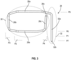
- the device 20 essentially comprises two parts better visible to the figure 2 And 3 , namely a first part in the form of a cradle 30 which extends between the drum 14 and the motor 16, and a second part 32 which extends on the side of one of the removable panels, here the front panel 12b.
- the first part is formed by a first portion of the pipe 26 which forms a loop delimiting the periphery of the cradle 30, and the second part is formed by a second portion of the pipe.
- the device 20 is configured to be mounted in the envelope 12 by dismantling and removing one of the removable facade panels, namely the front panel 12b in the example shown.
- the second portion 32 of the pipe 26 is located on the side of the panel 12b to facilitate the installation and fixing of the device 20 in the device.
- the cradle 30 extends from this panel 12b to the opposite front panel, here the rear panel.
- P3 comprises a rectilinear horizontal segment 36b which is located above the segments 26a of the intermediate plane, and which is parallel to a rectilinear horizontal segment 26c of the second plane P4.
- the second portion 32 of the pipe has a general L shape. It comprises a rectilinear horizontal segment 32a running along the segment 26c of the second plane P3. This second portion 32 further comprises a vertical rectilinear segment 32b.
- the segments 26a, 32b extend respectively in vertical planes P5, P6 and P7 parallel to each other and to the aforementioned plane P1.
- P1 is here located between P6 and P7.
- the cradle 30 has a width measured in the plane P2, between the segments 26a, which is less than the width of the second portion 32.
- the width of this portion 32 corresponds substantially to the length of the segment 32a of this portion.
- the pipe 26 can be fixed in two places on an element of the device 10, for example in zone Z1 on the inside of a facade panel of the envelope 12, and in zone Z2 on a casing made of material plastic located inside the envelope (for example that surrounding the motor 16 or a fan). Fixation can be done via plastic organs.
- One of these ends 26x of the pipe 26 is preferably equipped with a pressure sensor 34 which is configured to measure the pressure of the fluid 29 and which is connected to the control member 22 of the device 10.
- the member 22 is configured to put the device 10 in out-of-service mode when the pressure sensor 34 emits a signal corresponding to a pressure of the fluid 29 lower than a predetermined threshold.
- the member 22 can also be configured to emit a signal to a portable electronic device such as a smartphone-type mobile telephone, in order to warn the user or owner of the device in the event of a malfunction of the device. this last.
- the pipe 14 could be equipped with a sensor for measuring parameters other than pressure, such as temperature for example.
- the wall of the pipe 26 can be of the single-layer or multi-layer type. It can for example comprise two layers, respectively internal and external.
- the internal layer can be made of a material with low permeability compared to the extinguishing fluid 29, that is to say with a lower permeability or equal to 1 cm 3 .25 ⁇ m/m 2 .atm.24h. It is for example made of fluorinated thermoplastic or EVOH material.
- the outer layer is made of a polyamide thermoplastic material, which generally has a permeability greater than that of the inner layer, and for example greater than or equal to 1 cm 3 .25 ⁇ m/m 2 .atm.24h.
- the low permeability layer is located inside the higher permeability layer. Indeed, otherwise, there would be a risk of gas migrating through the internal layer with higher permeability and of stagnation of this gas at the interface between the two layers, likely to lead to delamination of the layers.
- a single-layer pipe should have a significant thickness of layer with low permeability. In the context of a two-layer or multi-layer pipe, this resistance is ensured by the layer(s) with higher permeability, and the layer with low permeability can have a relatively small thickness sufficient to ensure the desired impermeability function.
- the layer could be placed between two layers. This configuration would improve the mechanical strength of the layer during the pipe shaping stage (and thus avoid any risk of tearing of this layer), while guaranteeing optimal sealing of the pipe.
- At least one has a fuse property under the effect of the heat generated by a fire or the start of a fire, and in particular under the effect of a temperature greater than or equal to 70°C, or even 120°C.
- the two layers have such a fuse property.
- the pipe 26 has an external diameter of between 10 and 30 mm, and preferably between 10 and 20mm.
- the wall has a thickness of between 1 and 3mm, and preferably between 1 and 2mm.
- the pipe 26 has for example a length of between 1 and 5m
- the extinguishing fluid can be stored in the aforementioned space or cavity at a pressure greater than 1 bar and which can reach 10 bars, 20 bars, or even 30 bars.
- the extinguishing fluid preferably does not include HFC gas of the R236Fa type because this gas has a very high GWP or GWP of around 9400.
- the extinguishing fluid preferably has a GWP or GWP less than or equal to 5000.
- the fluid may comprise at least one HFC gas and/or C 6 F 12 O, and/or CO 2 .
- HFC gases that can be used, R227ea and R125 gases are preferred because they have a GWP or GWP of around 3400-3500.
- the DuPont ® company for example, markets gases of this type under the names FE-25 and FM-200.
- CO 2 is advantageous because it has a GWP or GWP of 1.
- C 6 F 12 O is also advantageous because it has a GWP or GWP of 1.
- the company 3M in particular markets this type of gas under the name Novec ® 1230 (FK-5-1-12).
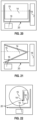
- THE figures 5 to 25 illustrate different variants illustrating several configurations for the device 10 and several possible installations and conformations for the device 20 and the pipe 16.
- the axis 15 of rotation of the drum 14 extends in the plane of the drawings. This axis is horizontal to figures 5 to 10 , 17 to 21 , and vertical to the Figure 25 . In the figures 11 to 16 , And 22 to 24 , this axis 15 is perpendicular to the plane of the drawings.
- the motor 16 and the heating system 18 can have different dimensions and positions in the envelope of the device 10. This is also the case for the belt 24.
- each of the parts of the pipe 14 can be adapted according to the dimensions and positions of the motor 16, and/or the system 18 and/or the belt 24.
- the device 20 may comprise several pipes 26 or a pipe 26 formed of several portions, segments or sections which are consecutive or disjointed from each other.
- the present invention also relates to a kit which comprises a device 20 as described in the above as well as fixings, such as the aforementioned plastic members, to allow the mounting and fixing of the device 20 and in particular of its pipe 26 in a device 10.
- This kit can therefore be considered as a conversion kit for a new or old device in order to equip it with an autonomous fire extinguishing device.
Landscapes
- Engineering & Computer Science (AREA)
- Textile Engineering (AREA)
- Health & Medical Sciences (AREA)
- Public Health (AREA)
- Business, Economics & Management (AREA)
- Emergency Management (AREA)
- Detail Structures Of Washing Machines And Dryers (AREA)
- Main Body Construction Of Washing Machines And Laundry Dryers (AREA)
Description
La présente invention concerne un appareil de séchage et/ou de lavage de linge équipé d'un système autonome d'extinction de feu ou départ de feu.The present invention relates to a laundry drying and/or washing appliance equipped with an autonomous fire extinguishing or fire starting system.
La demande de brevet
Un appareil de séchage et/ou de lavage de linge est un appareil électroménager qui comporte un tambour rotatif dans lequel on place du linge en vue de le laver avec de l'eau et un agent nettoyant, ou du linge humide pour le sécher par brassage. Le tambour est en général entraîné en rotation par une courroie elle-même entraînée par un moteur électrique. Un lave-linge peut avoir une fonction sèche-linge. Dans les deux cas, le tambour de l'appareil peut être traversé par un flux d'air chaud de façon à faciliter le séchage du linge lors de son brassage. Le système de chauffage et de génération du flux d'air chaud de l'appareil peut comprendre un brûleur à gaz ou une résistance électrique par exemple.A laundry drying and/or washing appliance is a household appliance which comprises a rotating drum in which laundry is placed for washing with water and a cleaning agent, or damp laundry for drying by stirring. . The drum is generally rotated by a belt which is itself driven by an electric motor. A washing machine can have a dryer function. In both cases, the drum of the device can be passed through by a flow of hot air so as to facilitate the drying of the laundry when it is tossed. The heating and hot air flow generation system of the device may include a gas burner or an electric resistance for example.
Cet appareil électroménager est à l'origine de nombreux incendies domestiques. Le chauffage et le brassage du linge dans le tambour génèrent des poussières inflammables qui s'accumulent à l'intérieur de l'appareil et qui sont susceptibles de s'enflammer, en particulier lorsqu'elles se déposent sur des parties très chaudes de l'appareil telles que le moteur ou le système de chauffage. Un démarrage de feu provoqué par l'inflammation des poussières peut provoquer un feu plus important dans l'appareil notamment par inflammation de la courroie d'entraînement du tambour.This household appliance is the cause of many domestic fires. Heating and stirring the laundry in the drum generates flammable dust which accumulates inside the appliance and which is likely to ignite, particularly when deposited on very hot parts of the appliance. device such as the engine or the heating system. A fire caused by the ignition of dust can cause a larger fire in the device, particularly by ignition of the drum drive belt.
La demande de brevet évoquée plus haut propose d'installer un réservoir sous forme d'une bombe sous pression dans un lave-linge, ce réservoir étant relié à des canalisations normalement fermées et susceptibles de se rompre à un seuil de température déterminé. Ces canalisations se prolongent jusqu'aux parties de l'appareil qui sont sujettes à subir des surchauffes ou à prendre feu, comme les dispositifs électriques, les résistances, le moteur, les composants inflammables, etc. La substance anti-incendie contenue dans le réservoir est au moins légèrement sous pression et les canalisations de distribution sont réalisées en une matière destinée à fondre pour assurer la rupture ou l'ouverture de ces canalisations lorsque ces dernières sont léchées par des flammes ou lorsque la température de leur environnement excède un seuil prédéterminé. De cette façon, dès qu'il se manifeste des conditions de surchauffe ou d'inflammabilité qui pourraient donner lieu à un incendie à l'intérieur de l'appareil, les canalisations se brisent et distribuent automatiquement la substance anti-incendie pour éteindre aussitôt le développement d'un incendie possible.The patent application mentioned above proposes installing a tank in the form of a pressure bomb in a washing machine, this tank being connected to pipes that are normally closed and likely to rupture at a determined temperature threshold. These pipes extend to parts of the device which are subject to overheating or catching fire, such as electrical devices, resistances, the motor, flammable components, etc. The fire-fighting substance contained in the tank is at least slightly under pressure and the distribution pipes are made of a material intended to melt to ensure the rupture or opening of these pipes when the latter are licked by flames or when the temperature of their environment exceeds a predetermined threshold. In this way, as soon as overheating or flammability conditions arise which could give rise to a fire inside the device, the pipes break and automatically distribute the fire-fighting substance to immediately extinguish the possible development of a fire.
La solution décrite dans cette demande de brevet n'est toutefois pas entièrement satisfaisante car le système d'extinction de feu formé par le réservoir et les canalisations est complexe et long à installer dans un appareil électroménager. En effet, il comprend plusieurs éléments qui doivent être installés et fixés les uns après les autres et raccordés les uns aux autres dans l'appareil. Ces éléments sont situés dans plusieurs zones à l'intérieur de l'appareil si bien que l'installation du système dans l'appareil ne peut se faire que lors de la fabrication de cet appareil. De la même façon, en cas de maintenance, il est nécessaire de démonter plusieurs panneaux de façade de l'appareil pour accéder au système. Le système décrit dans cette demande ne peut ainsi pas facilement être intégré dans un appareil existant qui n'aurait pas été conçu à l'origine pour être équipé avec ce système. L'état de la technique comprend également le document
L'invention propose un appareil de séchage et/ou de lavage de linge, comportant :
- une enveloppe externe de forme générale parallélépipédique et comprenant au moins un premier panneau de façade amovible,
- un tambour situé dans ladite enveloppe et mobile en rotation autour d'un axe, ce tambour comprenant une cavité interne configurée pour recevoir du linge,
- un moteur d'entraînement en rotation du tambour autour de son axe, ce moteur étant situé dans l'enveloppe sous le tambour, et
- un système de chauffage et de génération d'un flux d'air chaud à travers ladite cavité, ce système étant situé dans ladite enveloppe,
- caractérisé en ce qu'il comprend en outre un dispositif autonome d'extinction de feu, ce dispositif comportant :
- au moins un tuyau de forme allongée et fermé à ses deux extrémités longitudinales, ce tuyau comportant une paroi thermoplastique fusible délimitant un espace interne, ce tuyau étant thermoformé pour lui imposer une forme particulière à l'état libre sans contrainte correspondant à sa position de montage à l'intérieur de l'enveloppe, et
- un fluide extincteur à l'intérieur dudit espace, ce fluide extincteur étant configuré pour être libéré par fusion de la paroi du tuyau sous l'effet de la chaleur apportée par un feu ou départ de feu,
- et en ce que le dispositif est configuré pour être monté dans ladite enveloppe par démontage et retrait dudit premier panneau de façade, le dispositif comprenant deux parties, à savoir une première partie en forme de berceau qui s'étend entre le tambour et le moteur, depuis ledit premier panneau de façade jusqu'à un panneau de façade de l'enveloppe opposé audit premier panneau de façade, et une seconde partie qui s'étend du côté dudit premier panneau de façade, ladite première partie étant formée par une première portion du tuyau qui forme une boucle délimitant la périphérie dudit berceau, et ladite seconde partie étant formée par une seconde portion du tuyau.
- an external envelope of generally parallelepiped shape and comprising at least one first removable facade panel,
- a drum located in said envelope and movable in rotation around an axis, this drum comprising an internal cavity configured to receive laundry,
- a motor for rotating the drum around its axis, this motor being located in the casing under the drum, and
- a system for heating and generating a flow of hot air through said cavity, this system being located in said envelope,
- characterized in that it further comprises an autonomous fire extinguishing device, this device comprising:
- at least one pipe of elongated shape and closed at its two longitudinal ends, this pipe comprising a fusible thermoplastic wall delimiting an internal space, this pipe being thermoformed to impose a particular shape on it in the free state without constraint corresponding to its mounting position inside the envelope, and
- an extinguishing fluid inside said space, this extinguishing fluid being configured to be released by melting of the wall of the pipe under the effect of the heat provided by a fire or start of fire,
- and in that the device is configured to be mounted in said envelope by dismantling and removing said first facade panel, the device comprising two parts, namely a first part in the form of a cradle which extends between the drum and the motor, from said first facade panel to a facade panel of the envelope opposite said first facade panel, and a second part which extends on the side of said first facade panel, said first part being formed by a first portion of the pipe which forms a loop delimiting the periphery of said cradle, and said second part being formed by a second portion of the pipe.
Il est tout d'abord important de noter que le fluide, éventuellement sous pression, est directement stocké dans le tuyau et qu'il n'y a donc pas de réservoir indépendant raccordé à ce tuyau. Le tuyau a d'ailleurs ses deux extrémités qui sont fermées de manière étanche.It is first of all important to note that the fluid, possibly under pressure, is directly stored in the pipe and that there is therefore no independent tank connected to this pipe. The pipe also has its two ends which are closed in a watertight manner.
Le tuyau a une forme allongée et est réalisé dans un matériau facilitant d'une part sa mise en forme par chauffage (appelé thermoformage), avant son montage dans l'appareil, ainsi que autorisant la libération du fluide extincteur par fusion et éclatement.The pipe has an elongated shape and is made of a material facilitating on the one hand its shaping by heating (called thermoforming), before its assembly in the device, as well as allowing the release of the extinguishing fluid by melting and bursting.
Une des particularités du dispositif et du tuyau est qu'il est particulièrement conçu et a une forme spécifique pour son intégration dans un appareil de séchage et/ou de lavage de linge. Il présente un très faible encombrement. Le tuyau est agencé en deux portions. Une première portion du tuyau forme un berceau s'étendant entre le tambour et le moteur. Un berceau a en général une forme arrondie ou en creux, ce qui lui permet de s'étendre autour du tambour et d'épouser sa forme. Le tuyau forme une boucle ce qui lui permet de s'étendre sur toute la zone située entre le moteur et le tambour, qui est une zone critique d'apparition de feu, sans risque de perturbation du fonctionnement de l'appareil. La seconde portion du tuyau s'étend du côté du panneau de façade amovible et par exemple le long d'une partie de la courroie d'entraînement du tambour.One of the particularities of the device and the pipe is that it is particularly designed and has a specific shape for its integration into a laundry drying and/or washing appliance. It has a very small footprint. The pipe is arranged in two portions. A first portion of the pipe forms a cradle extending between the drum and the motor. A cradle generally has a rounded or hollow shape, which allows it to extend around the drum and conform to its shape. The pipe forms a loop which allows it to extend over the entire area between the motor and the drum, which is a critical area for the occurrence of fire, without risk of disrupting the operation of the device. The second portion of the pipe extends on the side of the removable facade panel and for example along part of the drum drive belt.
Un des avantages du dispositif est qu'il peut être facilement installé dans l'appareil, depuis une face de celui-ci, par démontage et retrait du panneau de façade correspondant qui est amovible. La forme générale du dispositif imposée par le thermoformage du tuyau est sa forme définitive. Cette forme facilite l'installation du dispositif dans l'appareil car, pour monter le dispositif, il suffit d'intercaler le berceau entre le tambour et le moteur puis de fixer la seconde portion du tuyau à l'enveloppe ou à un élément de l'appareil. Dans le cadre de la présente invention, on entend par berceau une structure en forme de boucle. Le berceau (sa structure ou sa boucle) peut s'étendre dans un plan ou peut définir une surface plane. En variante, le berceau (sa structure ou sa boucle) peut avoir une forme incurvée et définir une surface incurvée. Dans encore une autre variante, le berceau (sa structure ou sa boucle) a une forme plus complexe, voire est en au moins deux parties. L'appareil selon l'invention peut comprendre une ou plusieurs des caractéristiques suivantes, prises isolément les unes des autres ou en combinaison les unes avec les autres :
- ladite première partie en forme de berceau s'étend dans au moins deux plans sécants ;
- ladite première partie en forme de berceau s'étend dans trois plans sécants, à savoir :
- un plan intermédiaire horizontal dans lequel sont situés des segments rectilignes et parallèles du tuyau,
- un premier plan incliné situé du côté dudit panneau de façade opposé et s'étendant vers le haut depuis ledit plan intermédiaire, et
- un second plan incliné situé du côté dudit premier panneau de façade et s'étendant vers le haut depuis ledit plan intermédiaire ;
- le premier plan incliné comporte un segment rectiligne horizontal qui est situé au-dessus des segments rectilignes du plan intermédiaire, et qui est parallèle à un segment rectiligne horizontal du second plan ;
- la seconde portion du tuyau a une forme générale en L ;
- la seconde portion du tuyau comprend un segment rectiligne horizontal longeant le segment rectiligne horizontal du second plan ;
- la seconde portion du tuyau comprend un segment rectiligne vertical ;
- une des extrémités longitudinales du tuyau est équipée d'au moins un capteur qui est relié à un organe de contrôle;
- -- ledit organe de contrôle est accessible par un utilisateur via par exemple le panneau de commande de cet appareil ou tous autres moyens d'échange d'information (par exemple Wifi, Bluetooth®, IR, etc.);
- -- ledit organe de contrôle est un organe de commande de l'appareil ;
- le capteur est un capteur de pression, de température ou d'un ou plusieurs autre(s) paramètre(s) ;
- ledit organe peut être configuré pour mettre l'appareil en mode hors service lorsque ledit capteur émet un signal particulier ; par exemple, ledit organe est configuré pour mettre l'appareil en mode hors service lorsque ledit capteur de pression émet un signal correspondant à une pression dudit fluide inférieure à un seuil prédéterminé ;
- ledit organe est configuré pour émettre un signal à destination d'un dispositif électronique portable, tel qu'un ordinateur portable ou un téléphone portable du type smartphone par exemple ;
- -- ledit organe est configuré pour émettre un signal à destination d'un réseau informatique (par exemple domotique) ou d'une base de données informatique, tel qu'un réseau ou une base de données configuré pour assurer une gestion d'un parc de plusieurs appareils en vue de leur maintenance ;
- -- ladite émission de signal est réalisée sans fil à distance, par exemple par Wi-Fi, Bluetooth®, IR, etc. ;
- l'appareil comprend en outre une courroie d'entraînement monté autour du tambour ou de la poulie tambour et d'un arbre du moteur, la première partie du dispositif s'étendant entre la courroie et un panneau de façade de l'enveloppe ;
- ledit tuyau a une longueur comprise
entre 1 et 5m, et un diamètre compris entre 10 et 30mm ;- -- le dispositif est monobloc ;
- -- le tuyau est monobloc ; en variante, le tuyau est formé de plusieurs sections consécutives qui sont assemblées ou non les unes aux autres, directement ou par l'intermédiaire de connecteurs fluidiques ;
- -- le fluide est sous pression ;
- -- le fluide est à une pression supérieure à 1 bar et inférieure ou égale à 30 bars, de préférence comprise
entre 1 et 20 bars et par exemple compriseentre 1 et 10 bars ; - -- le fluide est à l'état liquide ou gazeux à température ambiante (comprise par exemple entre 15 et 25°C) ;
- - le système de chauffage et de génération d'un flux d'air chaud est situé sous le tambour ou sur un côté du tambour ;
- -- ledit berceau s'étend au-dessus dudit système de chauffage et de génération d'un flux d'air chaud ;
- -- ladite seconde partie ou portion du tuyau s'étend à proximité dudit système de chauffage et de génération d'un flux d'air chaud.
- said first cradle-shaped part extends in at least two intersecting planes;
- said first cradle-shaped part extends in three intersecting planes, namely:
- a horizontal intermediate plane in which rectilinear and parallel segments of the pipe are located,
- a first inclined plane located on the side of said opposite facade panel and extending upwards from said intermediate plane, and
- a second inclined plane located on the side of said first facade panel and extending upwards from said intermediate plane;
- the first inclined plane comprises a horizontal rectilinear segment which is located above the rectilinear segments of the intermediate plane, and which is parallel to a horizontal rectilinear segment of the second plane;
- the second portion of the pipe has a general L shape;
- the second portion of the pipe comprises a horizontal rectilinear segment running along the horizontal rectilinear segment of the second plane;
- the second portion of the pipe comprises a vertical rectilinear segment;
- one of the longitudinal ends of the pipe is equipped with at least one sensor which is connected to a control member;
- -- said control unit is accessible by a user via for example the control panel of this device or any other means of exchanging information (for example Wifi, Bluetooth® , IR, etc.);
- -- said control body is a control body of the device;
- the sensor is a pressure sensor, a temperature sensor or one or more other parameter(s);
- said member can be configured to put the device in out-of-service mode when said sensor emits a particular signal; for example, said member is configured to put the device in out-of-service mode when said pressure sensor emits a signal corresponding to a pressure of said fluid below a predetermined threshold;
- said member is configured to emit a signal to a portable electronic device, such as a laptop computer or a mobile phone of the smartphone type for example;
- -- said body is configured to emit a signal to a computer network (for example home automation) or a computer database, such as a network or a database configured to ensure management of a park several devices for maintenance;
- -- said signal transmission is carried out wirelessly at a distance, for example by Wi-Fi, Bluetooth ® , IR, etc. ;
- the apparatus further comprises a drive belt mounted around the drum or the drum pulley and a motor shaft, the first part of the device extending between the belt and a front panel of the envelope;
- said pipe has a length of between 1 and 5m, and a diameter of between 10 and 30mm;
- -- the device is in one piece;
- -- the pipe is in one piece; alternatively, the pipe is formed of several consecutive sections which are assembled or not with each other, directly or via fluid connectors;
- -- the fluid is under pressure;
- -- the fluid is at a pressure greater than 1 bar and less than or equal to 30 bars, preferably between 1 and 20 bars and for example between 1 and 10 bars;
- -- the fluid is in the liquid or gaseous state at ambient temperature (for example between 15 and 25°C);
- - the heating and hot air flow generation system is located under the drum or on one side of the drum;
- -- said cradle extends above said system for heating and generating a flow of hot air;
- -- said second part or portion of the pipe extends close to said system for heating and generating a flow of hot air.
La présente invention concerne également un kit pour un appareil tel que décrit ci-dessus, caractérisé en ce qu'il comprend :
- + un dispositif autonome d'extinction de feu, ce dispositif comportant :
- au moins un tuyau de forme allongée et fermé à ses deux extrémités longitudinales, ce tuyau comportant une paroi thermoplastique fusible délimitant un espace interne, ce tuyau étant thermoformé pour lui imposer une forme particulière à l'état libre sans contrainte correspondant à sa position de montage à l'intérieur de l'enveloppe, et
- un fluide extincteur à l'intérieur dudit espace, ce fluide extincteur étant configuré pour être libéré par fusion de la paroi du tuyau sous l'effet de la chaleur apportée par un feu ou départ de feu,
- le dispositif étant configuré pour être monté dans l'enveloppe de l'appareil par démontage et retrait dudit premier panneau de façade, le dispositif comprenant deux parties, à savoir une première partie en forme de berceau qui s'étend entre le tambour et le moteur, depuis ledit premier panneau de façade jusqu'à un panneau de façade de l'enveloppe opposé audit premier panneau de façade, et une seconde partie qui s'étend du côté dudit premier panneau de façade, ladite première partie étant formée par une première portion du tuyau qui forme une boucle délimitant la périphérie dudit berceau, et ladite seconde partie étant formée par une seconde portion du tuyau, et
- + des fixations du dispositif à l'appareil.
- + an autonomous fire extinguishing device, this device comprising:
- at least one pipe of elongated shape and closed at its two longitudinal ends, this pipe comprising a fusible thermoplastic wall delimiting an internal space, this pipe being thermoformed to impose a particular shape on it in the free state without constraint corresponding to its mounting position inside the envelope, and
- an extinguishing fluid inside said space, this extinguishing fluid being configured to be released by melting of the wall of the pipe under the effect of the heat provided by a fire or start of fire,
- the device being configured to be mounted in the envelope of the apparatus by dismantling and removing said first facade panel, the device comprising two parts, namely a first part in the form of a cradle which extends between the drum and the motor , from said first facade panel to a facade panel of the envelope opposite said first facade panel, and a second part which extends on the side of said first facade panel, said first part being formed by a first portion of the pipe which forms a loop delimiting the periphery of said cradle, and said second part being formed by a second portion of the pipe, and
- + fixings of the device to the device.
L'invention sera mieux comprise et d'autres détails, caractéristiques et avantages de l'invention apparaîtront plus clairement à la lecture de la description suivante faite à titre d'exemple non limitatif et en référence aux dessins annexés dans lesquels :
- [
Fig.1 ] lafigure 1 est une vue schématique en perspective et en transparence d'un appareil de séchage et/ou de lavage de linge selon l'invention, - [
Fig. 2 ] lafigure 2 est une vue schématique en perspective du dispositif d'extinction de feu destiné à être installé dans l'appareil de lafigure 1 , - [
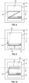
Fig. 3 ] lafigure 3 est une autre vue schématique en perspective du système de lafigure 2 , - [
Fig. 4 ] lafigure 4 est une vue schématique en coupe transversale du dispositif d'extinction de feu et en particulier de son tuyau, et - [
Fig. 5-25 ] lesfigures 5 à 25 illustrent plusieurs variantes d'installation d'un dispositif d'extinction de feu dans un appareil selon l'invention.
- [
Fig.1 ] therefigure 1 is a schematic perspective and transparency view of a laundry drying and/or washing device according to the invention, - [
Fig. 2 ] therefigure 2 is a schematic perspective view of the fire extinguishing device intended to be installed in the appliance of thefigure 1 , - [
Fig. 3 ] thereFigure 3 is another schematic perspective view of the system of thefigure 2 , - [
Fig. 4 ] therefigure 4 is a schematic cross-sectional view of the fire extinguishing device and in particular of its pipe, and - [
Fig. 5-25 ] THEfigures 5 to 25 illustrate several variants of installation of a fire extinguishing device in a device according to the invention.
La
L'appareil 10 comprend une enveloppe externe 12 de forme générale parallélépipédique dans laquelle sont situés:
un tambour 14 mobile en rotation autour d'unaxe 15 et comprenant une cavité interne 17 configurée pour recevoir le linge,- un moteur 16 d'entraînement en rotation du tambour 14 autour de
son axe 15, qui est situé sous le tambour 14, un système 18 de chauffage et de génération d'un flux d'air chaud à travers ladite cavité, etun dispositif 20 autonome d'extinction de feu.
- a
drum 14 movable in rotation around anaxis 15 and comprising aninternal cavity 17 configured to receive the laundry, - a
motor 16 for driving thedrum 14 in rotation around itsaxis 15, which is located under thedrum 14, - a
system 18 for heating and generating a flow of hot air through said cavity, and - an autonomous
fire extinguishing device 20.
L'enveloppe 12 comprend plusieurs panneaux de façade 12a, 12b dont certains sont amovibles. De façon connue, un appareil 10 de ce type peut comprendre une trappe 19 de chargement par le dessus ou par l'avant. Lorsque l'appareil comprend une trappe de chargement par le dessus, l'appareil comprend des panneaux de façade, au nombre de 4 (avant, arrière et latéraux), dont au moins certains sont amovibles pour accéder, après démontage et retrait d'au moins un de ces panneaux, à l'intérieur de l'enveloppe et de l'appareil. Lorsque l'appareil comprend une trappe de chargement par le devant, sous forme d'hublot par exemple, l'appareil comprend des panneaux de façades dont au moins un panneau latéral est amovible pour la même raison.The
Le tambour 14 définit un volume de lavage et/ou de séchage quelconque et qui est adapté à son utilisation (particulier ou professionnel).The
Comme cela est visible à la
Le moteur 16 comprend un arbre de sortie (non visible) qui entraîne en rotation le tambour 14 autour de son axe 15 par l'intermédiaire d'une courroie 24. La courroie 24 s'étend autour du tambour 14 et de l'arbre de sortie du moteur 16, ou d'une poulie entraînée par cet arbre, et s'étend globalement dans un plan P1 sensiblement horizontal. Dans l'exemple représenté, le plan P1 est parallèle aux panneaux de façade latéraux 12a de l'appareil10. L'axe de rotation du tambour 14 est lui aussi horizontal et perpendiculaire à ces panneaux 12a. Dans le cas d'un appareil à trappe d'ouverture à hublot par le devant ou frontale, le plan P1 s'étendrait parallèlement au panneau de façade arrière de l'appareil et l'axe de rotation du tambour serait perpendiculaire à ce panneau arrière.The
Le système de chauffage 18 peut être de n'importe quel type et est par exemple du type à résistance chauffante, à brûleur à gaz, etc. Le système 18 peut être situé sous le tambour 14 ou sur un côté du tambour 14.The
Le dispositif 20 d'extinction de feu est spécifiquement conçu pour être intégré dans l'appareil 10 et comprend un tuyau 26 de forme allongée et fermée à ses deux extrémités longitudinales.The
Les extrémités du tuyau 26 peuvent être fermées par des bouchons rapportés et fixés sur le tuyau, par exemple par collage ou soudage. En variante, les extrémités du tuyau 26 pourraient être directement fermées par déformation et soudage de son matériau.The ends of the
Le tuyau 26 comporte une paroi thermoplastique fusible délimitant un espace interne 28 dans lequel est stocké un fluide extincteur 29, éventuellement sous pression (cf.
Au moins l'une des extrémités du tuyau 26 pourrait être équipée d'une vanne de remplissage du tuyau en fluide extincteur 29, comme cela est décrit dans la demande
Le fluide extincteur 29 est configuré pour être libéré par fusion de la paroi du tuyau sous l'effet de la chaleur apportée par un feu ou départ de feu,The extinguishing
Le tuyau 26 est thermoformé pour lui imposer une forme particulière à l'état libre sans contrainte correspondant à sa position de montage à l'intérieur de l'enveloppe 12. Le matériau du tuyau sera décrit plus en détail dans ce qui suit en référence à la
Le dispositif 20 comprend pour l'essentiel deux parties mieux visible aux
Le dispositif 20 est configuré pour être monté dans l'enveloppe 12 par démontage et retrait d'un des panneaux de façade amovibles, à savoir le panneau avant 12b dans l'exemple représenté.The
La seconde portion 32 du tuyau 26 est située du côté du panneau 12b pour faciliter la pose et la fixation du dispositif 20 dans l'appareil. Le berceau 30 s'étend depuis ce panneau 12b jusqu'au panneau de façade opposé, ici le panneau arrière.The
On comprend que le démontage et le retrait du panneau 12b suffit à accéder au dispositif 20 et surtout suffit pour monter et fixer ce dispositif dans l'enveloppe 12. La forme en berceau de la première portion du tuyau 26 facilite son insertion autour du tambour 14, et entre ce tambour 14 et le moteur 16.It will be understood that disassembly and removal of the
Les
- P2 est un plan intermédiaire horizontal dans lequel sont situés des
segments 26a rectilignes et parallèles du tuyau, - P3 est un premier plan incliné situé du côté du panneau arrière et s'étendant vers le haut depuis le plan intermédiaire P2, et
- P4 est un second plan incliné situé du côté du panneau avant 12b et s'étendant vers le haut depuis le plan intermédiaire P2.
- P2 is a horizontal intermediate plane in which rectilinear and
parallel segments 26a of the pipe are located, - P3 is a first inclined plane located on the side of the rear panel and extending upwards from the intermediate plane P2, and
- P4 is a second inclined plane located on the side of the
front panel 12b and extending upwards from the intermediate plane P2.
P3 comporte un segment 36b rectiligne horizontal qui est situé au-dessus des segments 26a du plan intermédiaire, et qui est parallèle à un segment 26c rectiligne horizontal du second plan P4.P3 comprises a rectilinear horizontal segment 36b which is located above the
La seconde portion 32 du tuyau a une forme générale en L. Elle comprend un segment 32a rectiligne horizontal longeant le segment 26c du second plan P3. Cette seconde portion 32 comprend en outre un segment 32b rectiligne vertical.The
On constate que les segments 26a, 32b s'étendent respectivement dans des plans verticaux P5, P6 et P7 parallèles entre eux et au plan P1 précité. P1 est ici situé entre P6 et P7. Autrement dit, le berceau 30 a une largeur mesurée dans le plan P2, entre les segments 26a, qui est inférieure à la largeur de la seconde portion 32. La largeur de cette portion 32 correspond sensiblement à la longueur du segment 32a de cette portion.It can be seen that the
On constate que les deux extrémités libres 26x du tuyau 26 sont respectivement portées par le segment 26c et par le segment 32b.It can be seen that the two
Le tuyau 26 peut être fixé à deux endroits sur un élément de l'appareil 10, par exemple dans la zone Z1 sur l'intérieur d'un panneau de façade de l'enveloppe 12, et dans la zone Z2 sur un carter en matériau plastique situé à l'intérieur de l'enveloppe (par exemple celui entourant le moteur 16 ou un ventilateur). La fixation peut se faire par l'intermédiaire d'organes plastiques. Une de ces extrémités 26x du tuyau 26 est de préférence équipée d'un capteur de pression 34 qui est configuré pour mesurer la pression du fluide 29 et qui est relié à l'organe 22 de contrôle et de commande de l'appareil 10. L'organe 22 est configuré pour mettre l'appareil 10 en mode hors service lorsque le capteur de pression 34 émet un signal correspondant à une pression du fluide 29 inférieure à un seuil prédéterminé. L'organe 22 peut en outre être configuré pour émettre un signal à destination d'un dispositif électronique portable tel qu'un téléphone portable du type smartphone, afin d'avertir l'utilisateur ou le propriétaire de l'appareil en cas de dysfonctionnement de ce dernier.The
En variante, le tuyau 14 pourrait être équipé d'un capteur de mesure d' autres paramètres que la pression, tel que la température par exemple.Alternatively, the
Comme cela est schématiquement représenté à la
La couche interne peut être réalisée dans un matériau à faible perméabilité par rapport au fluide extincteur 29, c'est-à-dire à une perméabilité inférieure ou égale à 1 cm3.25µm/m2.atm.24h. Elle est par exemple réalisée en matériau thermoplastique fluoré ou EVOH.The internal layer can be made of a material with low permeability compared to the extinguishing
La couche externe est réalisée dans un matériau thermoplastique polyamide, qui a elle en général une perméabilité supérieure à celle de la couche interne, et par exemple supérieure ou égale à 1 cm3.25µm/m2.atm.24h.The outer layer is made of a polyamide thermoplastic material, which generally has a permeability greater than that of the inner layer, and for example greater than or equal to 1 cm 3 .25µm/m 2 .atm.24h.
Il est préférable que la couche à faible perméabilité soit située à l'intérieur de la couche à plus forte perméabilité. En effet, dans le cas contraire, il y aurait un risque de migration du gaz à travers la couche interne à plus forte perméabilité et de stagnation de ce gaz à l'interface entre les deux couches, susceptible d'entraîner un délaminage des couches.It is preferable that the low permeability layer is located inside the higher permeability layer. Indeed, otherwise, there would be a risk of gas migrating through the internal layer with higher permeability and of stagnation of this gas at the interface between the two layers, likely to lead to delamination of the layers.
Il est par ailleurs avantageux de réaliser le tuyau en deux couches plutôt qu'en une seule couche en matériau à faible perméabilité car ce matériau est relativement coûteux. Pour avoir une tenue suffisante, notamment à la pression, un tuyau monocouche devrait avoir une épaisseur importante de couche à faible perméabilité. Dans le cadre d'un tuyau bicouche ou multicouche, cette tenue est assurée par la ou les couches à plus forte perméabilité, et la couche à faible perméabilité peut avoir une épaisseur relativement faible suffisante pour assurer la fonction d'imperméabilité recherchée.It is also advantageous to make the pipe in two layers rather than in a single layer of low permeability material because this material is relatively expensive. To have sufficient resistance, particularly to pressure, a single-layer pipe should have a significant thickness of layer with low permeability. In the context of a two-layer or multi-layer pipe, this resistance is ensured by the layer(s) with higher permeability, and the layer with low permeability can have a relatively small thickness sufficient to ensure the desired impermeability function.
Dans une autre variante non représentée, la couche pourrait être disposée entre deux couches. Cette configuration permettrait d'améliorer la tenue mécanique de la couche lors de l'étape de mise en forme du tuyau (et ainsi éviter tout risque de déchirure de cette couche), tout en garantissant une étanchéité optimale du tuyau.In another variant not shown, the layer could be placed between two layers. This configuration would improve the mechanical strength of the layer during the pipe shaping stage (and thus avoid any risk of tearing of this layer), while guaranteeing optimal sealing of the pipe.
Parmi les matériaux de la paroi, au moins un a une propriété fusible sous l'effet de la chaleur générée par un feu ou un départ de feu, et en particulier sous l'effet d'une température supérieure ou égale à 70°C, voire 120°C. Dans l'exemple décrit plus haut, les deux couches ont une telle propriété fusible.Among the materials of the wall, at least one has a fuse property under the effect of the heat generated by a fire or the start of a fire, and in particular under the effect of a temperature greater than or equal to 70°C, or even 120°C. In the example described above, the two layers have such a fuse property.
Dans un exemple particulier de réalisation de l'invention, le tuyau 26 a un diamètre externe compris entre 10 et 30mm, et de préférence entre 10 et 20mm. La paroi a une épaisseur comprise entre 1 et 3mm, et de préférence entre 1 et 2mm. Le tuyau 26 a par exemple une longueur comprise entre 1 et 5mIn a particular embodiment of the invention, the
Le fluide extincteur peut être stocké dans l'espace ou la cavité précitée à une pression supérieure à 1 bar et qui peut atteindre 10 bars, 20 bars, voire 30 bars.The extinguishing fluid can be stored in the aforementioned space or cavity at a pressure greater than 1 bar and which can reach 10 bars, 20 bars, or even 30 bars.
Le fluide extincteur ne comprend de préférence pas de gaz HFC du type R236Fa car ce gaz a un PRP ou PRG très important de l'ordre de 9400.The extinguishing fluid preferably does not include HFC gas of the R236Fa type because this gas has a very high GWP or GWP of around 9400.
Le fluide extincteur a de préférence un PRP ou PRG inférieur ou égal à 5000. Le fluide peut comprendre au moins un gaz HFC et/ou du C6F12O, et/ou du CO2. Parmi les gaz HFC utilisables, les gaz R227ea et R125 sont préférés car ils ont un PRP ou PRG de l'ordre de 3400-3500. La société DuPont® commercialise par exemple des gaz de ce type sous les dénominations FE-25 et FM-200.The extinguishing fluid preferably has a GWP or GWP less than or equal to 5000. The fluid may comprise at least one HFC gas and/or C 6 F 12 O, and/or CO 2 . Among the HFC gases that can be used, R227ea and R125 gases are preferred because they have a GWP or GWP of around 3400-3500. The DuPont ® company, for example, markets gases of this type under the names FE-25 and FM-200.
Le CO2 est avantageux car il a un PRP ou PRG de 1.CO 2 is advantageous because it has a GWP or GWP of 1.
Enfin, le C6F12O est également avantageux car il a un PRP ou PRG de 1. La société 3M notamment commercialise ce type de gaz sous la dénomination Novec® 1230 (FK-5-1-12).Finally, C 6 F 12 O is also advantageous because it has a GWP or GWP of 1. The company 3M in particular markets this type of gas under the name Novec ® 1230 (FK-5-1-12).
Les
Les éléments déjà décrits dans ce qui précède et illustrés dans les dessins sont désignés par les mêmes références.The elements already described in the above and illustrated in the drawings are designated by the same references.
Dans les
On constate que le moteur 16 et le système de chauffage 18 peuvent avoir des dimensions et des positions différentes dans l'enveloppe de l'appareil 10. C'est également le cas de la courroie 24.It can be seen that the
On constate également que la forme, les dimensions, et la position de chacune des parties du tuyau 14 peuvent être adaptées en fonction des dimensions et positions du moteur 16, et/ou du système 18 et/ou de la courroie 24. On constate également aux
La présente invention concerne également un kit qui comprend un dispositif 20 tel que décrit dans ce qui précède ainsi que des fixations, tels que les organes plastiques précités, pour permettre le montage et la fixation du dispositif 20 et en particulier de son tuyau 26 dans un appareil 10. Ce kit peut donc être considéré comme un kit de transformation d'un appareil neuf ou ancien afin de l'équiper d'un dispositif autonome d'extinction de feu.The present invention also relates to a kit which comprises a
Claims (15)
- An appliance (10) for drying and/or washing laundry, comprising:- an external enclosure (12) of generally parallelepipedic shape and comprising at least one first removable face panel (12b),- a drum (14) located in said enclosure (12) and rotatable about an axis (15), this drum comprising an internal cavity (17) configured to receive laundry,- a motor (16) for driving in rotation the drum (14) about its axis (15), this motor being located in the enclosure (12) under the drum (14), and- a system (18) for heating and generating a flow of hot air through said cavity (17), this system being located in said enclosure (12),characterised in that it also comprises an autonomous fire extinguishing device (20), this device comprising:- at least one pipe (26) with an elongate shape and closed at both its longitudinal ends (26x), this pipe comprising a fusible thermoplastic wall delimiting an internal space, this pipe being thermoformed in order to impose on it a particular shape in the unconstrained free state corresponding to its mounting position inside the enclosure (12), and- a fire-extinguishing fluid (29) within said space, this fire-extinguishing fluid being configured to be released by fusion of the wall of the pipe (26) under the effect of the heat provided by a fire or a fire departure,and in that the device (20) is configured to be mounted in said enclosure (12) by dismounting and removing said first face panel (12b), the device (20) comprising two portions, referred to as a first portion in the shape of cradle (30) which extends between the drum (14) and the motor (16), from said first face panel (12b) to a face panel of the enclosure opposite said first face panel, and a second portion (32) which extends on the side of said first face panel (12b), said first portion being formed by a first segment of the pipe (26) which forms a loop delimiting the periphery of said cradle (30), and said second portion being formed by a second segment of the pipe (26).
- The appliance (10) of claim 1, wherein said first cradle portion (30) extends in at least two intersecting planes (P2, P3, P4).
- The appliance (10) according to claim 2, wherein said first cradle portion (30) extends in three intersecting planes, referred to as:- a horizontal intermediate plane (P2) in which straight and parallel sectors (26a) of the pipe are located,- a first inclined plane (P3) located on the side of said opposite face panel and extending upwards from said intermediate plane (P2), and- a second inclined plane (P4) located on the side of said first face panel (12b) and extending upwards from said intermediate plane (P2).
- The appliance (10) according to claim 3, wherein the first inclined plane (P3) comprises a horizontal straight sector (26b) which is located above the straight sectors (26a) of the intermediate plane (P2), and which is parallel to a horizontal straight sector (26c) of the second plane (P3).
- The appliance (10) according to any of the preceding claims, wherein the second segment (32) of the pipe (26) is generally L-shaped.
- The appliance (10) according to claim 5, in dependence on claim 4, wherein the second segment (32) of the pipe (26) comprises a horizontal straight sector (32a) running alongside the horizontal straight sector (26c) of the second plane (P3).
- The appliance (10) according to any of the preceding claims, wherein the second segment (32) of the pipe (26) comprises a vertical straight sector (32b).
- The appliance (10) according to one of the preceding claims, wherein one of the longitudinal ends (26x) of the pipe (26) is equipped with at least one sensor (34) which is connected to a control member (22).
- The appliance (10) according to claim 8, wherein said member (22) is configured to put the appliance into a disable mode when said pressure sensor (34) emits a particular signal.
- The appliance (10) according to claim 8 or 9, wherein said sensor (34) is a pressure, temperature or other parameter sensor.
- The appliance (10) according to any of the preceding claims, wherein said member (22) is configured to emit a signal to an electronic device, a computer network, or a computer database.
- The appliance (10) according to any of the preceding claims, wherein it further comprises a drive belt (24) mounted around the drum (14) and a motor shaft (16), the first portion of the device (20) extending between the belt (24) and a face panel (12b) of the enclosure (12).
- The appliance (10) according to any of the preceding claims, wherein said pipe (26) has a length between 1 and 5m, and a diameter between 10 and 30mm.
- The appliance (10) according to any of the preceding claims, wherein said heating and hot air flow generation system (18) is located under the drum (14) or on one side of the drum.
- A kit for an appliance (10) according to one of the preceding claims, characterised in that it comprises:- the autonomous fire extinguishing device (20), this device comprising:- at least one pipe (26) of elongated shape and closed at both its longitudinal ends (26x), this pipe comprising a fusible thermoplastic wall delimiting an internal space, this pipe being thermoformed in order to impose on it a particular shape in the free state without constraint corresponding to its mounting position inside the enclosure (12), and- a fire-extinguishing fluid (29) within said space, this fire-extinguishing fluid being configured to be released by fusion of the wall of the pipe (26) under the effect of the heat provided by a fire or a fire departure,the device (20) being configured to be mounted in the enclosure (12) of the appliance by dismounting and removing said first face panel (12b), the device (20) comprising two portions, referred to as a first portion in the shape of cradle (30) which extends between the drum (14) and the motor (16), from said first face panel (12b) to a face panel of the enclosure opposite said first face panel and a second portion (32) which extends on the side of said first face panel (12b), said first portion being formed by a first segment of the pipe (26) which forms a loop delimiting the periphery of said cradle (30), and said second portion being formed by a second segment of the pipe (26), and- attachments for attaching the device (20) to the appliance.
Applications Claiming Priority (2)
| Application Number | Priority Date | Filing Date | Title |
|---|---|---|---|
| FR2005219A FR3110608B1 (en) | 2020-05-20 | 2020-05-20 | LAUNDRY DRYING AND/OR WASHING APPLIANCE EQUIPPED WITH AN AUTONOMOUS FIRE EXTINGUISHING SYSTEM |
| PCT/EP2021/058936 WO2021233605A1 (en) | 2020-05-20 | 2021-04-06 | Appliance for drying and/or washing laundry equipped with an autonomous fire extinguishing system |
Publications (2)
| Publication Number | Publication Date |
|---|---|
| EP4153805A1 EP4153805A1 (en) | 2023-03-29 |
| EP4153805B1 true EP4153805B1 (en) | 2024-05-01 |
Family
ID=72178739
Family Applications (1)
| Application Number | Title | Priority Date | Filing Date |
|---|---|---|---|
| EP21717051.3A Active EP4153805B1 (en) | 2020-05-20 | 2021-04-06 | Appliance for drying and/or washing laundry equipped with an autonomous fire extinguishing system |
Country Status (6)
| Country | Link |
|---|---|
| US (1) | US20230220603A1 (en) |
| EP (1) | EP4153805B1 (en) |
| CN (1) | CN115768938A (en) |
| FR (1) | FR3110608B1 (en) |
| MX (1) | MX2022014323A (en) |
| WO (1) | WO2021233605A1 (en) |
Families Citing this family (1)
| Publication number | Priority date | Publication date | Assignee | Title |
|---|---|---|---|---|
| FR3132529A1 (en) | 2022-02-10 | 2023-08-11 | Hutchinson | LAUNDRY DRYING AND/OR WASHING APPLIANCE EQUIPPED WITH A SELF-CONTAINED FIRE EXTINGUISHING DEVICE |
Family Cites Families (5)
| Publication number | Priority date | Publication date | Assignee | Title |
|---|---|---|---|---|
| ES2006865A6 (en) | 1987-04-24 | 1989-05-16 | Faini Spa | Fire-extenguishing device for electrical equipment having flammable components |
| SE532446C2 (en) * | 2007-04-12 | 2010-01-19 | Electrolux Ab | Fire protection system for a clothes dryer |
| DE102007061521A1 (en) * | 2007-12-20 | 2009-06-25 | BSH Bosch und Siemens Hausgeräte GmbH | Clothes drying apparatus and method for operating a laundry drying apparatus |
| DE102012200075B3 (en) * | 2012-01-04 | 2013-02-21 | BSH Bosch und Siemens Hausgeräte GmbH | Clothes dryer such as household clothes dryer has temperature-activated release unit which releases extinguishing agent into space outside of drum, so that extinguishing agent is released automatically at temperature caused by fire |
| FR3088215B1 (en) * | 2018-11-12 | 2023-05-12 | Hutchinson | EXTINGUISHER HOSE AND METHOD OF MANUFACTURING IT |
-
2020
- 2020-05-20 FR FR2005219A patent/FR3110608B1/en active Active
-
2021
- 2021-04-06 EP EP21717051.3A patent/EP4153805B1/en active Active
- 2021-04-06 WO PCT/EP2021/058936 patent/WO2021233605A1/en unknown
- 2021-04-06 MX MX2022014323A patent/MX2022014323A/en unknown
- 2021-04-06 US US17/999,040 patent/US20230220603A1/en active Pending
- 2021-04-06 CN CN202180042415.3A patent/CN115768938A/en active Pending
Also Published As
| Publication number | Publication date |
|---|---|
| EP4153805A1 (en) | 2023-03-29 |
| MX2022014323A (en) | 2023-02-27 |
| US20230220603A1 (en) | 2023-07-13 |
| FR3110608A1 (en) | 2021-11-26 |
| FR3110608B1 (en) | 2022-04-15 |
| WO2021233605A1 (en) | 2021-11-25 |
| CN115768938A (en) | 2023-03-07 |
Similar Documents
| Publication | Publication Date | Title |
|---|---|---|
| EP1251257B1 (en) | Jet engine air intake fairing with de-icing device | |
| CA2502526C (en) | Condensation heat exchanger with plastic casing | |
| EP4153805B1 (en) | Appliance for drying and/or washing laundry equipped with an autonomous fire extinguishing system | |
| EP0918149B1 (en) | Protection device for the air inlet of a jet engine which is provided with an anti-icing system | |
| WO2015079166A1 (en) | Combustion assembly having facilitated access to the prevaporization tubes | |
| EP3880314B1 (en) | Fire-extinguishing hose for a battery compartment or a motor vehicle | |
| EP2497385A1 (en) | Removable silencer for a hairdryer and hairdryer provided with such a silencer | |
| WO2023152219A1 (en) | Apparatus for drying and/or washing laundry provided with an autonomous fire extinguishing device | |
| EP3759394B1 (en) | Combustion chamber having a double chamber bottom | |
| LU88109A1 (en) | DEVICE INCORPORATED IN A MIRROR TO AVOID FOG FORMATION | |
| FR2695473A1 (en) | Measuring device for determining gas turbidity. | |
| FR2912277A1 (en) | Electrical heating apparatus, has screen with insulator whose melting temperature is greater than melting temperature of sheath, and heating element that is in contact with rear face connected to earth when sheath is melted | |
| FR2703575A1 (en) | Device with thermometer for holding a liquid to be heated, such as a water-bath type bottle-warming receptacle or baby's bottle | |
| FR3130926A1 (en) | Cryogenic fluid storage unit | |
| FR3106368A1 (en) | VEHICLE CATALYTIC CONTAINER INTENDED TO REDUCE POLLUTANT EMISSIONS | |
| EP4063759B1 (en) | System for heating water | |
| FR2616716A1 (en) | Heat-insulating diesel fuel heater | |
| FR2677705A1 (en) | Device for the thermal protection of the peripheral members of a combustion engine equipped with a turbocompressor | |
| FR2816394A1 (en) | DOMESTIC RADIATION AND CONVECTION HEATING APPARATUS | |
| EP4306181A1 (en) | Motor vehicle equipped with a battery pack with fire extinguishing device | |
| WO2023118745A1 (en) | Integrating an extinguisher into a "fire" zone of a turbomachine | |
| FR2944338A1 (en) | Strainer for fuel injection system in turboshaft engine of aircraft, has interior space delimited by filtering structure through which fuel is circulated from space towards outside of strainer, and heating systems electrically powered | |
| WO2014111445A1 (en) | Packaging for transporting and/or storing radioactive substances, comprising improved protection against fire | |
| FR3115334A1 (en) | Pump for cryogenic fluid | |
| EP0725588A1 (en) | Liquid heating device with thermometer, such as a baby bottle warming receptacle with a water bath, or a baby bottle |
Legal Events
| Date | Code | Title | Description |
|---|---|---|---|
| STAA | Information on the status of an ep patent application or granted ep patent |
Free format text: STATUS: UNKNOWN |
|
| STAA | Information on the status of an ep patent application or granted ep patent |
Free format text: STATUS: THE INTERNATIONAL PUBLICATION HAS BEEN MADE |
|
| PUAI | Public reference made under article 153(3) epc to a published international application that has entered the european phase |
Free format text: ORIGINAL CODE: 0009012 |
|
| STAA | Information on the status of an ep patent application or granted ep patent |
Free format text: STATUS: REQUEST FOR EXAMINATION WAS MADE |
|
| 17P | Request for examination filed |
Effective date: 20221208 |
|
| AK | Designated contracting states |
Kind code of ref document: A1 Designated state(s): AL AT BE BG CH CY CZ DE DK EE ES FI FR GB GR HR HU IE IS IT LI LT LU LV MC MK MT NL NO PL PT RO RS SE SI SK SM TR |
|
| DAV | Request for validation of the european patent (deleted) | ||
| DAX | Request for extension of the european patent (deleted) | ||
| GRAP | Despatch of communication of intention to grant a patent |
Free format text: ORIGINAL CODE: EPIDOSNIGR1 |
|
| STAA | Information on the status of an ep patent application or granted ep patent |
Free format text: STATUS: GRANT OF PATENT IS INTENDED |
|
| INTG | Intention to grant announced |
Effective date: 20240122 |
|
| GRAS | Grant fee paid |
Free format text: ORIGINAL CODE: EPIDOSNIGR3 |
|
| GRAA | (expected) grant |
Free format text: ORIGINAL CODE: 0009210 |
|
| STAA | Information on the status of an ep patent application or granted ep patent |
Free format text: STATUS: THE PATENT HAS BEEN GRANTED |
|
| AK | Designated contracting states |
Kind code of ref document: B1 Designated state(s): AL AT BE BG CH CY CZ DE DK EE ES FI FR GB GR HR HU IE IS IT LI LT LU LV MC MK MT NL NO PL PT RO RS SE SI SK SM TR |
|
| REG | Reference to a national code |
Ref country code: GB Ref legal event code: FG4D Free format text: NOT ENGLISH |
|
| REG | Reference to a national code |
Ref country code: CH Ref legal event code: EP |
|
| REG | Reference to a national code |
Ref country code: IE Ref legal event code: FG4D Free format text: LANGUAGE OF EP DOCUMENT: FRENCH |
|
| REG | Reference to a national code |
Ref country code: DE Ref legal event code: R096 Ref document number: 602021012708 Country of ref document: DE |