EP3342466B1 - Brandschutzvorrichtung zur durchführung durch eine wand - Google Patents
Brandschutzvorrichtung zur durchführung durch eine wand Download PDFInfo
- Publication number
- EP3342466B1 EP3342466B1 EP16306835.6A EP16306835A EP3342466B1 EP 3342466 B1 EP3342466 B1 EP 3342466B1 EP 16306835 A EP16306835 A EP 16306835A EP 3342466 B1 EP3342466 B1 EP 3342466B1
- Authority
- EP
- European Patent Office
- Prior art keywords
- wall
- stop device
- fire stop
- orifice
- fire
- Prior art date
- Legal status (The legal status is an assumption and is not a legal conclusion. Google has not performed a legal analysis and makes no representation as to the accuracy of the status listed.)
- Active
Links
Images
Classifications
-
- A—HUMAN NECESSITIES
- A62—LIFE-SAVING; FIRE-FIGHTING
- A62C—FIRE-FIGHTING
- A62C2/00—Fire prevention or containment
- A62C2/06—Physical fire-barriers
- A62C2/12—Hinged dampers
-
- A—HUMAN NECESSITIES
- A62—LIFE-SAVING; FIRE-FIGHTING
- A62C—FIRE-FIGHTING
- A62C2/00—Fire prevention or containment
- A62C2/06—Physical fire-barriers
- A62C2/065—Physical fire-barriers having as the main closure device materials, whose characteristics undergo an irreversible change under high temperatures, e.g. intumescent
-
- A—HUMAN NECESSITIES
- A62—LIFE-SAVING; FIRE-FIGHTING
- A62C—FIRE-FIGHTING
- A62C2/00—Fire prevention or containment
- A62C2/06—Physical fire-barriers
- A62C2/24—Operating or controlling mechanisms
- A62C2/241—Operating or controlling mechanisms having mechanical actuators and heat sensitive parts
- A62C2/242—Operating or controlling mechanisms having mechanical actuators and heat sensitive parts with fusible links
-
- F—MECHANICAL ENGINEERING; LIGHTING; HEATING; WEAPONS; BLASTING
- F16—ENGINEERING ELEMENTS AND UNITS; GENERAL MEASURES FOR PRODUCING AND MAINTAINING EFFECTIVE FUNCTIONING OF MACHINES OR INSTALLATIONS; THERMAL INSULATION IN GENERAL
- F16L—PIPES; JOINTS OR FITTINGS FOR PIPES; SUPPORTS FOR PIPES, CABLES OR PROTECTIVE TUBING; MEANS FOR THERMAL INSULATION IN GENERAL
- F16L5/00—Devices for use where pipes, cables or protective tubing pass through walls or partitions
- F16L5/02—Sealing
- F16L5/04—Sealing to form a firebreak device
Definitions
- the invention relates to a fire-stop device for passing through a wall, in particular to allow a fluid and/or an electric cable and/or a fluid conduit to pass through the wall.
- Such a device generally comprises a wall-passing sleeve provided with a main body and a passage orifice, in particular for the passage of fluid, and/or electric cable, and/or fluid conduit, said sleeve being configured so that the main body is housed in said wall and the inlet orifice is arranged outside the wall.
- a shutter closes the gravity passage hole so that when the device is installed in the wall, the shutter closes the hole.
- the shutter is advantageously provided with a plug made of intumescent material.
- the firestop device allows a door between two areas to remain closed, with cables and/or conduits passing from one area to the other through the firestop device.
- EP 0 524 078 A1 discloses a fire-stopping device for ensuring the passage through a partition wall between two zones of an installation, of cables and/or flexible conduits for the supply of electrical or other energy.
- JP 2006 071264 A discloses a ventilation device having an external communication port of an air duct and a foam material attached thereto.
- the foam material melts in the event of a fire nearby to block the external communication port.
- a fire protection element comprising a metal support with openings separated by ribs, which in the event of fire ensure a seal against fire and smoke.
- WO 83/03552 A1 discloses a fire barrier for pipe penetrations, in which, in the event of a fire, a closing element cuts the pipe and closes the open section of the pipe in a flame-tight manner.
- the aim of the invention is to remedy these drawbacks.
- the device according to the present invention makes it possible to maintain the passage orifice in the open position, which ensures the equal pressure of zones or the evacuation of fluids with which the wall crossed by the device forms an interface.
- the thermally fusible element melts; the shutter is no longer held in the open position and falls by gravity onto the passage opening, which delays the progression of the fire.
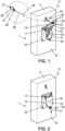
- the invention relates to a fire-stop device for passing through a wall, referenced 1 in the figures.
- the fire-stop device 1 is illustrated in the installed position in a wall or partition, referenced 2.
- Wall 2 forms the border between a first zone Z and a second zone Z.
- Device 1 allows a fluid and/or an electric cable and/or a fluid conduit to pass through the wall.
- a set of cables 4 passes through the wall 2 via the device 1.
- the device 1 comprises a sleeve 5 for crossing the wall 2.
- the sleeve 5 comprises a main body and at least one passage orifice.
- the sleeve 5 comprises two half-sleeves 7, 8 separated by an interval 9 to prevent a thermal bridge between the two half-sheaths 7, 8.
- Each half-sheath 7, 8 is provided at one of its ends with an orifice 10 for the passage of the set of cables and/or conduits 4.
- half-sleeve 8 is preferably identical to the half-sleeve 7, so that the same description also applies to the half-sleeve 8.
- the half-sheath 7 comprises a main body 12 housed in the wall 2, the passage orifice 10 being arranged outside the wall 2.
- the main body 12 comprises a part 13 inside the wall 2, while a part 14 projects out of a face 15 of the wall 2, in the first zone Z.
- the main body 12 has a generally cylindrical shape extending in a main direction L.
- the half-sheath 7 also includes a flap 16 for closing the passage orifice 10 by gravity.
- the shutter 16 is movable between an opening position of the passage orifice 10, illustrated in the figure 1 and a closing position of the passage orifice 10, illustrated in the figure 2 .
- the half-sleeve 7 comprises a rod 17 for pivoting the shutter 16 between the open position and the closed position.
- the rod 17 extends in a direction parallel to a plane P of the face 15.
- the rod 17 is arranged opposite the external part 14 of the main body 13.
- the rod 17 In the installed position in the wall 2, the rod 17 is mounted above the main body 13, which ensures that the stable position of the shutter 16 is the closed position, while the open position is never stable.
- the shutter 16 comprises a cover 18 on which a plug 19 rests.
- the plug 19 is made of an intumescent material.
- the plug 19 is arranged so as to block the passage orifice 10 in the closed position of the shutter 16.
- the cover 18 comprises a fork 20 provided with two teeth 21 spaced from each other, diametrically opposite the rod 17.
- the teeth 21 are each perforated with a hole 22.
- a bar 23 passes through the two holes 22, at least one of the ends of the bar 23 projecting out of the holes 22.
- the fire-stop device 1 comprises a finger 24 secured to the external part 14 and arranged opposite the fork 20 so that in the closed position, the teeth 21 of the fork 20 are arranged on either side of the finger 24.
- the fire-stop device 1 comprises a control member 25 for controlling the position of the shutter 16.
- the control member 25 comprises a thermally fusible element 26, otherwise called a thermal fuse.
- the thermal fuse 26 is arranged so as to keep the shutter in the open position.
- the thermal fuse 26 comprises two ends, each being perforated respectively with a hole 27.
- a chain 28 connects the thermal fuse 26 to the shutter 16.
- One end 29 of the chain 28 is secured to the thermal fuse 26, while one end 30 of the chain 28 is secured to the bar 23.
- a hoop 31 passes through the other hole 27 to secure the thermal fuse 26 to the face 15 of the wall 2.
- the thermal fuse 26 secured to the shutter 16 keeps the shutter 16 in the open position of the passage orifice 10.
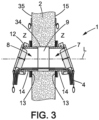
- the fire-stop device comprises a grid 32 in the main body 13 of the half-sheath 7.
- the grid 32 is mounted substantially orthogonally to the direction L.
- the grid 32 includes a fire-resistant protective coating.
- the fire protection coating preferably comprises at least one layer of refractory glue.
- the refractory glue comprises, in a known manner, active elements which release water when the temperature rises, for example above 80°C. By vaporizing at 100°C, this water slows down the propagation of heat from the outer (hot) side of the coating to its inner (cold) side.
- active elements which release water when the temperature rises, for example above 80°C. By vaporizing at 100°C, this water slows down the propagation of heat from the outer (hot) side of the coating to its inner (cold) side.
- F.active glue based on metal oxide hydrates, can be used.
- the grid comprises at least one layer of incombustible material of the calcium silicate type.
- the layer of non-combustible material is in contact with the fire protection coating.
- the holes in the grid 32 are small enough not to allow a pin to pass through during fire tests.
- the fire-stop device 1 comprises a support 33 for fixing the half-sheath 7 to the face 15 of the wall 2, a plate of intumescent material (not visible) forming a seal between the fixing support 33 and the face 15.
- half-sleeve 8 is similar to that of the half-sleeve 7.
- main body 12 of the half-sleeve 8 extends in the extension of the main body 12 of the half-sleeve 7.
- each of the cylinders 12 extends in the same main direction L.
- the half-sleeves 7, 8 are driven into a core hole 34 of the wall 2, the half-sleeve 7 opening into the face 15 (as already described), while the half-sleeve 8 opens into a face 35 of the wall 2 and opposite the face 15.
- the set 4 of cables and/or conduits enters the half-sheath 7 through the passage orifice 10, passes through the main body 13 of the half-sheath 7, the gap 9 then the main body 12 of the half-sheath 7 and exits the fire-stop device 1 through the passage orifice 10 of the half-sheath 8.
- each shutter 16 In the normal operating position of the fire-stop device 1, that is to say when the fire-stop device 1 is installed in the wall 2 and no fire is occurring, each shutter 16 is in the open position of the associated passage opening 10.
- the intumescent material of the plug 19 swells, which prevents the spread of fire.
- the grid also helps to slow down the fire between the Z zones, through the layers of materials constituting it.
Landscapes
- Health & Medical Sciences (AREA)
- Public Health (AREA)
- Business, Economics & Management (AREA)
- Emergency Management (AREA)
- Engineering & Computer Science (AREA)
- Mechanical Engineering (AREA)
- Installation Of Indoor Wiring (AREA)
- Building Environments (AREA)
Claims (8)
- Brandschutzvorrichtung zur Durchführung durch eine Wand (2), insbesondere zum Ermöglichen der Durchführung eines Fluids und/oder ein elektrischen Kabels und/oder einer Fluidleitung durch die Wand, wobei die Vorrichtung eine Wanddurchführungshülse (5) umfasst, die mit einem Hauptkörper (12) und einer Durchgangsöffnung (10), insbesondere für den Durchgang von Fluid und/oder eines elektrischen Kabels und/oder einer Fluidleitung, versehen ist, wobei die Hülse (5) so konfiguriert ist, dass der Hauptkörper (12) mindestens teilweise in der Wand untergebracht ist und die Einlassöffnung (10) außerhalb der Wand (2) angeordnet ist, wobei die Brandschutzvorrichtung (1) eine Verschlussklappe (16) für die Durchgangsöffnung (10) durch Schwerkraft umfasst, wobei die Klappe (16) schwenkbar zwischen einer Schließposition der Durchgangsöffnung (10) und einer Öffnungsposition der Durchgangsöffnung (10) montiert ist, wobei die Vorrichtung (1) ein Steuerelement (25) für die Position der Klappe (16) zwischen der Öffnungsposition und der Schließposition umfasst, wobei das Steuerelement (25) ein thermisch schmelzbares Element (26) umfasst, das so angeordnet ist, dass es die Klappe (16) in der Öffnungsposition hält, wobei die Klappe (16) mit einem Stopfen (19) aus intumeszierendem Material ausgestattet ist, wobei der Stopfen (19) so angeordnet ist, dass er in der Schließposition der Klappe (16) die Durchgangsöffnung (10) verschließt,wobei ein Ende des thermisch schmelzbaren Endes (26) ein Loch (27) umfasst,wobei in der Öffnungsposition eine Kette (28) die Klappe (16) von dem Loch (27) aus mit dem thermisch schmelzbaren Element (26) verbindet.
- Brandschutzvorrichtung nach Anspruch 1, die ein Gitter (32) im Hauptkörper (12) der Hülse (5) umfasst.
- Brandschutzvorrichtung nach dem vorhergehenden Anspruch, wobei das Gitter (32) eine Brandschutzbeschichtung umfasst.
- Brandschutzvorrichtung nach dem vorhergehenden Anspruch, wobei die Brandschutzbeschichtung mindestens eine Schicht aus feuerfestem Klebstoff umfasst, wobei der Klebstoff aktive Elemente umfasst, die bei einem Temperaturanstieg Wasser freisetzen können.
- Brandschutzvorrichtung nach einem der Ansprüche 2 bis 4, wobei das Gitter (32) mindestens eine Schicht aus nicht brennbarem Material vom Typ Kalziumsilikat umfasst.
- Brandschutzvorrichtung nach einem der vorhergehenden Ansprüche, die eine Montagehalterung (33) für die Vorrichtung (1) an der Wand (2) und eine Platte aus intumeszierendem Material umfasst, die eine Dichtung zwischen der Montagehalterung für die Vorrichtung und der Wand bildet.
- Brandschutzvorrichtung nach einem der vorhergehenden Ansprüche, wobei die Hülse (5) zwei Überzugshälften (7, 8) umfasst, die durch einen Spalt (9) getrennt sind, um die Bildung einer Wärmebrücke zu verhindern, wobei die Durchgangsöffnung (10) das Ende einer der beiden Überzugshälften (7) bildet.
- Brandschutzvorrichtung nach dem vorhergehenden Anspruch, die eine zweite Austrittsöffnung (10) umfasst, die das Ende der anderen Überzugshälfte (8) bildet.
Priority Applications (1)
| Application Number | Priority Date | Filing Date | Title |
|---|---|---|---|
| EP16306835.6A EP3342466B1 (de) | 2016-12-28 | 2016-12-28 | Brandschutzvorrichtung zur durchführung durch eine wand |
Applications Claiming Priority (1)
| Application Number | Priority Date | Filing Date | Title |
|---|---|---|---|
| EP16306835.6A EP3342466B1 (de) | 2016-12-28 | 2016-12-28 | Brandschutzvorrichtung zur durchführung durch eine wand |
Publications (2)
| Publication Number | Publication Date |
|---|---|
| EP3342466A1 EP3342466A1 (de) | 2018-07-04 |
| EP3342466B1 true EP3342466B1 (de) | 2024-08-21 |
Family
ID=57794100
Family Applications (1)
| Application Number | Title | Priority Date | Filing Date |
|---|---|---|---|
| EP16306835.6A Active EP3342466B1 (de) | 2016-12-28 | 2016-12-28 | Brandschutzvorrichtung zur durchführung durch eine wand |
Country Status (1)
| Country | Link |
|---|---|
| EP (1) | EP3342466B1 (de) |
Families Citing this family (4)
| Publication number | Priority date | Publication date | Assignee | Title |
|---|---|---|---|---|
| AU2021309129A1 (en) * | 2020-07-14 | 2023-03-09 | Ig6 Pty Ltd | An improved fire collar |
| GB2622097B (en) * | 2022-09-05 | 2024-12-25 | Intumescent Systems Ltd | Through-wall apparatus for cabling |
| CN115954812A (zh) * | 2022-09-30 | 2023-04-11 | 广东广船国际海洋科技研究院有限公司 | 用于线缆的防火结构 |
| WO2025114648A1 (fr) * | 2023-11-27 | 2025-06-05 | Baumert Sasu | Dispositif coupe-feu de passage à travers une paroi et paroi équipée d'au moins un tel dispositif |
Citations (1)
| Publication number | Priority date | Publication date | Assignee | Title |
|---|---|---|---|---|
| WO1983003552A1 (fr) * | 1982-04-14 | 1983-10-27 | Donner, Siegfried | Barriere coupe-feu pour traversees de tuyaux |
Family Cites Families (4)
| Publication number | Priority date | Publication date | Assignee | Title |
|---|---|---|---|---|
| DE3643708A1 (de) * | 1986-12-20 | 1988-06-30 | Bayer Ag | Intumeszenzmassen und ihre verwendung |
| FR2678839B1 (fr) * | 1991-07-12 | 1993-11-12 | Electricite De France | Dispositif coupe-feu de traversee d'une paroi pour le passage de conduits de liaison temporaire. |
| DE10060252A1 (de) * | 2000-06-27 | 2002-01-10 | Illbruck Gmbh | Brandschutzelement |
| JP4790301B2 (ja) * | 2004-08-03 | 2011-10-12 | 積水化学工業株式会社 | 建物の換気装置 |
-
2016
- 2016-12-28 EP EP16306835.6A patent/EP3342466B1/de active Active
Patent Citations (1)
| Publication number | Priority date | Publication date | Assignee | Title |
|---|---|---|---|---|
| WO1983003552A1 (fr) * | 1982-04-14 | 1983-10-27 | Donner, Siegfried | Barriere coupe-feu pour traversees de tuyaux |
Also Published As
| Publication number | Publication date |
|---|---|
| EP3342466A1 (de) | 2018-07-04 |
Similar Documents
| Publication | Publication Date | Title |
|---|---|---|
| EP3342466B1 (de) | Brandschutzvorrichtung zur durchführung durch eine wand | |
| CH616193A5 (de) | ||
| FR2698676A1 (fr) | Vanne thermosensible. | |
| EP4155213B1 (de) | Flugzeug mit einer diwasserstofftransportleitung und einem eingrabenkanal der besagten transportleitung | |
| WO2012056117A1 (fr) | Porte étanche et coupe feu | |
| EP0918149B1 (de) | Schutzeinrichtung für den mit einem Enteisungssystem versehenen Lufteinlauf eines Strahltriebwerks | |
| FR2770411A1 (fr) | Clapet pare-feu pour conduit d'aeration | |
| FR2805591A1 (fr) | Dispositif thermostatique a deux regimes de regulation commandes selectivement | |
| BE1018652A5 (fr) | Clapet anti-feu et anti-fumee. | |
| EP0805314A1 (de) | Verschlussorgan für Ventil, Ventil mit Verschlussorgan und ein System, bestehend aus einem, durch eine Wand abdichtenden, Rahmen und einem, mit einem Verschlussorgan versehenen und in diesem Rahmen eingebauten, Ventil | |
| EP0524078B1 (de) | Feuersperranlage von Wandöffnungen für den Durchgang von Röhren von temporärer Verbindung | |
| EP1029558B1 (de) | Brandschutzventil | |
| EP2366436B1 (de) | Brandlöschvorrichtung für Blindwand | |
| FR2686399A1 (fr) | Dispositif de chauffage ou foyer au gaz a evacuation directe et valve de securite pour lesdits dispositifs de chauffage. | |
| KR0123879Y1 (ko) | 자동소화장치 | |
| WO2014128383A2 (fr) | Installation de lutte contre les incendies, incluant un réseau de sprinklers sous vide, incluant au moins une tête ouverte d'écoulement d'eau | |
| CA2298178A1 (fr) | Dispositif de securite pour robinet a eau chaude sanitaire et robinet notamment thermostatique pourvu du dit element de securite | |
| FR2733023A1 (fr) | Obturateur de clapet, clapet muni d'un obturateur et systeme d'un cadre a sceller a travers une paroi et d'un clapet muni d'un obturateur a monter dans ce cadre | |
| BE902087A (fr) | Clapet coupe-feu. | |
| FR2689602A1 (fr) | Dispositif permettant de couper un circuit de fluide en cas d'incendie. | |
| EP4678245A1 (de) | Bidirektionales brandschutz-absperrventil mit versetzter achse | |
| FR2739033A1 (fr) | Installation de ventilation | |
| FR2800620A1 (fr) | Dispositif coupe-feu formant element de conduit | |
| EP4608524A1 (de) | Feuerfester und wasserdichter bodenablauf | |
| EP1095672A1 (de) | Brandschützende Ventilationsöffnung |
Legal Events
| Date | Code | Title | Description |
|---|---|---|---|
| PUAI | Public reference made under article 153(3) epc to a published international application that has entered the european phase |
Free format text: ORIGINAL CODE: 0009012 |
|
| STAA | Information on the status of an ep patent application or granted ep patent |
Free format text: STATUS: THE APPLICATION HAS BEEN PUBLISHED |
|
| STAA | Information on the status of an ep patent application or granted ep patent |
Free format text: STATUS: REQUEST FOR EXAMINATION WAS MADE |
|
| AK | Designated contracting states |
Kind code of ref document: A1 Designated state(s): AL AT BE BG CH CY CZ DE DK EE ES FI FR GB GR HR HU IE IS IT LI LT LU LV MC MK MT NL NO PL PT RO RS SE SI SK SM TR |
|
| AX | Request for extension of the european patent |
Extension state: BA ME |
|
| 17P | Request for examination filed |
Effective date: 20180612 |
|
| RBV | Designated contracting states (corrected) |
Designated state(s): AL AT BE BG CH CY CZ DE DK EE ES FI FR GB GR HR HU IE IS IT LI LT LU LV MC MK MT NL NO PL PT RO RS SE SI SK SM TR |
|
| STAA | Information on the status of an ep patent application or granted ep patent |
Free format text: STATUS: EXAMINATION IS IN PROGRESS |
|
| 17Q | First examination report despatched |
Effective date: 20200608 |
|
| P01 | Opt-out of the competence of the unified patent court (upc) registered |
Effective date: 20230526 |
|
| GRAP | Despatch of communication of intention to grant a patent |
Free format text: ORIGINAL CODE: EPIDOSNIGR1 |
|
| STAA | Information on the status of an ep patent application or granted ep patent |
Free format text: STATUS: GRANT OF PATENT IS INTENDED |
|
| INTG | Intention to grant announced |
Effective date: 20240318 |
|
| GRAS | Grant fee paid |
Free format text: ORIGINAL CODE: EPIDOSNIGR3 |
|
| GRAA | (expected) grant |
Free format text: ORIGINAL CODE: 0009210 |
|
| STAA | Information on the status of an ep patent application or granted ep patent |
Free format text: STATUS: THE PATENT HAS BEEN GRANTED |
|
| AK | Designated contracting states |
Kind code of ref document: B1 Designated state(s): AL AT BE BG CH CY CZ DE DK EE ES FI FR GB GR HR HU IE IS IT LI LT LU LV MC MK MT NL NO PL PT RO RS SE SI SK SM TR |
|
| REG | Reference to a national code |
Ref country code: GB Ref legal event code: FG4D Free format text: NOT ENGLISH |
|
| REG | Reference to a national code |
Ref country code: CH Ref legal event code: EP |
|
| REG | Reference to a national code |
Ref country code: IE Ref legal event code: FG4D Free format text: LANGUAGE OF EP DOCUMENT: FRENCH |
|
| REG | Reference to a national code |
Ref country code: DE Ref legal event code: R096 Ref document number: 602016088976 Country of ref document: DE |
|
| REG | Reference to a national code |
Ref country code: LT Ref legal event code: MG9D |
|
| REG | Reference to a national code |
Ref country code: NL Ref legal event code: MP Effective date: 20240821 |
|
| PG25 | Lapsed in a contracting state [announced via postgrant information from national office to epo] |
Ref country code: NO Free format text: LAPSE BECAUSE OF FAILURE TO SUBMIT A TRANSLATION OF THE DESCRIPTION OR TO PAY THE FEE WITHIN THE PRESCRIBED TIME-LIMIT Effective date: 20241121 |
|
| REG | Reference to a national code |
Ref country code: AT Ref legal event code: MK05 Ref document number: 1714972 Country of ref document: AT Kind code of ref document: T Effective date: 20240821 |
|
| PG25 | Lapsed in a contracting state [announced via postgrant information from national office to epo] |
Ref country code: GR Free format text: LAPSE BECAUSE OF FAILURE TO SUBMIT A TRANSLATION OF THE DESCRIPTION OR TO PAY THE FEE WITHIN THE PRESCRIBED TIME-LIMIT Effective date: 20241122 Ref country code: FI Free format text: LAPSE BECAUSE OF FAILURE TO SUBMIT A TRANSLATION OF THE DESCRIPTION OR TO PAY THE FEE WITHIN THE PRESCRIBED TIME-LIMIT Effective date: 20240821 Ref country code: PT Free format text: LAPSE BECAUSE OF FAILURE TO SUBMIT A TRANSLATION OF THE DESCRIPTION OR TO PAY THE FEE WITHIN THE PRESCRIBED TIME-LIMIT Effective date: 20241223 Ref country code: PL Free format text: LAPSE BECAUSE OF FAILURE TO SUBMIT A TRANSLATION OF THE DESCRIPTION OR TO PAY THE FEE WITHIN THE PRESCRIBED TIME-LIMIT Effective date: 20240821 Ref country code: NL Free format text: LAPSE BECAUSE OF FAILURE TO SUBMIT A TRANSLATION OF THE DESCRIPTION OR TO PAY THE FEE WITHIN THE PRESCRIBED TIME-LIMIT Effective date: 20240821 |
|
| PG25 | Lapsed in a contracting state [announced via postgrant information from national office to epo] |
Ref country code: BG Free format text: LAPSE BECAUSE OF FAILURE TO SUBMIT A TRANSLATION OF THE DESCRIPTION OR TO PAY THE FEE WITHIN THE PRESCRIBED TIME-LIMIT Effective date: 20240821 |
|
| PG25 | Lapsed in a contracting state [announced via postgrant information from national office to epo] |
Ref country code: LV Free format text: LAPSE BECAUSE OF FAILURE TO SUBMIT A TRANSLATION OF THE DESCRIPTION OR TO PAY THE FEE WITHIN THE PRESCRIBED TIME-LIMIT Effective date: 20240821 |
|
| PG25 | Lapsed in a contracting state [announced via postgrant information from national office to epo] |
Ref country code: AT Free format text: LAPSE BECAUSE OF FAILURE TO SUBMIT A TRANSLATION OF THE DESCRIPTION OR TO PAY THE FEE WITHIN THE PRESCRIBED TIME-LIMIT Effective date: 20240821 Ref country code: IS Free format text: LAPSE BECAUSE OF FAILURE TO SUBMIT A TRANSLATION OF THE DESCRIPTION OR TO PAY THE FEE WITHIN THE PRESCRIBED TIME-LIMIT Effective date: 20241221 |
|
| PG25 | Lapsed in a contracting state [announced via postgrant information from national office to epo] |
Ref country code: HR Free format text: LAPSE BECAUSE OF FAILURE TO SUBMIT A TRANSLATION OF THE DESCRIPTION OR TO PAY THE FEE WITHIN THE PRESCRIBED TIME-LIMIT Effective date: 20240821 |
|
| PG25 | Lapsed in a contracting state [announced via postgrant information from national office to epo] |
Ref country code: RS Free format text: LAPSE BECAUSE OF FAILURE TO SUBMIT A TRANSLATION OF THE DESCRIPTION OR TO PAY THE FEE WITHIN THE PRESCRIBED TIME-LIMIT Effective date: 20241121 Ref country code: ES Free format text: LAPSE BECAUSE OF FAILURE TO SUBMIT A TRANSLATION OF THE DESCRIPTION OR TO PAY THE FEE WITHIN THE PRESCRIBED TIME-LIMIT Effective date: 20240821 |
|
| PG25 | Lapsed in a contracting state [announced via postgrant information from national office to epo] |
Ref country code: RS Free format text: LAPSE BECAUSE OF FAILURE TO SUBMIT A TRANSLATION OF THE DESCRIPTION OR TO PAY THE FEE WITHIN THE PRESCRIBED TIME-LIMIT Effective date: 20241121 Ref country code: PT Free format text: LAPSE BECAUSE OF FAILURE TO SUBMIT A TRANSLATION OF THE DESCRIPTION OR TO PAY THE FEE WITHIN THE PRESCRIBED TIME-LIMIT Effective date: 20241223 Ref country code: PL Free format text: LAPSE BECAUSE OF FAILURE TO SUBMIT A TRANSLATION OF THE DESCRIPTION OR TO PAY THE FEE WITHIN THE PRESCRIBED TIME-LIMIT Effective date: 20240821 Ref country code: NO Free format text: LAPSE BECAUSE OF FAILURE TO SUBMIT A TRANSLATION OF THE DESCRIPTION OR TO PAY THE FEE WITHIN THE PRESCRIBED TIME-LIMIT Effective date: 20241121 Ref country code: NL Free format text: LAPSE BECAUSE OF FAILURE TO SUBMIT A TRANSLATION OF THE DESCRIPTION OR TO PAY THE FEE WITHIN THE PRESCRIBED TIME-LIMIT Effective date: 20240821 Ref country code: LV Free format text: LAPSE BECAUSE OF FAILURE TO SUBMIT A TRANSLATION OF THE DESCRIPTION OR TO PAY THE FEE WITHIN THE PRESCRIBED TIME-LIMIT Effective date: 20240821 Ref country code: IS Free format text: LAPSE BECAUSE OF FAILURE TO SUBMIT A TRANSLATION OF THE DESCRIPTION OR TO PAY THE FEE WITHIN THE PRESCRIBED TIME-LIMIT Effective date: 20241221 Ref country code: HR Free format text: LAPSE BECAUSE OF FAILURE TO SUBMIT A TRANSLATION OF THE DESCRIPTION OR TO PAY THE FEE WITHIN THE PRESCRIBED TIME-LIMIT Effective date: 20240821 Ref country code: GR Free format text: LAPSE BECAUSE OF FAILURE TO SUBMIT A TRANSLATION OF THE DESCRIPTION OR TO PAY THE FEE WITHIN THE PRESCRIBED TIME-LIMIT Effective date: 20241122 Ref country code: FI Free format text: LAPSE BECAUSE OF FAILURE TO SUBMIT A TRANSLATION OF THE DESCRIPTION OR TO PAY THE FEE WITHIN THE PRESCRIBED TIME-LIMIT Effective date: 20240821 Ref country code: ES Free format text: LAPSE BECAUSE OF FAILURE TO SUBMIT A TRANSLATION OF THE DESCRIPTION OR TO PAY THE FEE WITHIN THE PRESCRIBED TIME-LIMIT Effective date: 20240821 Ref country code: BG Free format text: LAPSE BECAUSE OF FAILURE TO SUBMIT A TRANSLATION OF THE DESCRIPTION OR TO PAY THE FEE WITHIN THE PRESCRIBED TIME-LIMIT Effective date: 20240821 Ref country code: AT Free format text: LAPSE BECAUSE OF FAILURE TO SUBMIT A TRANSLATION OF THE DESCRIPTION OR TO PAY THE FEE WITHIN THE PRESCRIBED TIME-LIMIT Effective date: 20240821 |
|
| PG25 | Lapsed in a contracting state [announced via postgrant information from national office to epo] |
Ref country code: RO Free format text: LAPSE BECAUSE OF FAILURE TO SUBMIT A TRANSLATION OF THE DESCRIPTION OR TO PAY THE FEE WITHIN THE PRESCRIBED TIME-LIMIT Effective date: 20240821 Ref country code: SM Free format text: LAPSE BECAUSE OF FAILURE TO SUBMIT A TRANSLATION OF THE DESCRIPTION OR TO PAY THE FEE WITHIN THE PRESCRIBED TIME-LIMIT Effective date: 20240821 Ref country code: DK Free format text: LAPSE BECAUSE OF FAILURE TO SUBMIT A TRANSLATION OF THE DESCRIPTION OR TO PAY THE FEE WITHIN THE PRESCRIBED TIME-LIMIT Effective date: 20240821 |
|
| PG25 | Lapsed in a contracting state [announced via postgrant information from national office to epo] |
Ref country code: EE Free format text: LAPSE BECAUSE OF FAILURE TO SUBMIT A TRANSLATION OF THE DESCRIPTION OR TO PAY THE FEE WITHIN THE PRESCRIBED TIME-LIMIT Effective date: 20240821 |
|
| PG25 | Lapsed in a contracting state [announced via postgrant information from national office to epo] |
Ref country code: CZ Free format text: LAPSE BECAUSE OF FAILURE TO SUBMIT A TRANSLATION OF THE DESCRIPTION OR TO PAY THE FEE WITHIN THE PRESCRIBED TIME-LIMIT Effective date: 20240821 |
|
| PG25 | Lapsed in a contracting state [announced via postgrant information from national office to epo] |
Ref country code: SK Free format text: LAPSE BECAUSE OF FAILURE TO SUBMIT A TRANSLATION OF THE DESCRIPTION OR TO PAY THE FEE WITHIN THE PRESCRIBED TIME-LIMIT Effective date: 20240821 Ref country code: IT Free format text: LAPSE BECAUSE OF FAILURE TO SUBMIT A TRANSLATION OF THE DESCRIPTION OR TO PAY THE FEE WITHIN THE PRESCRIBED TIME-LIMIT Effective date: 20240821 |
|
| REG | Reference to a national code |
Ref country code: DE Ref legal event code: R097 Ref document number: 602016088976 Country of ref document: DE |
|
| PLBE | No opposition filed within time limit |
Free format text: ORIGINAL CODE: 0009261 |
|
| STAA | Information on the status of an ep patent application or granted ep patent |
Free format text: STATUS: NO OPPOSITION FILED WITHIN TIME LIMIT |
|
| REG | Reference to a national code |
Ref country code: DE Ref legal event code: R119 Ref document number: 602016088976 Country of ref document: DE |
|
| PG25 | Lapsed in a contracting state [announced via postgrant information from national office to epo] |
Ref country code: MC Free format text: LAPSE BECAUSE OF FAILURE TO SUBMIT A TRANSLATION OF THE DESCRIPTION OR TO PAY THE FEE WITHIN THE PRESCRIBED TIME-LIMIT Effective date: 20240821 |
|
| 26N | No opposition filed |
Effective date: 20250522 |
|
| REG | Reference to a national code |
Ref country code: CH Ref legal event code: PL |
|
| PG25 | Lapsed in a contracting state [announced via postgrant information from national office to epo] |
Ref country code: LU Free format text: LAPSE BECAUSE OF NON-PAYMENT OF DUE FEES Effective date: 20241228 |
|
| PG25 | Lapsed in a contracting state [announced via postgrant information from national office to epo] |
Ref country code: SE Free format text: LAPSE BECAUSE OF FAILURE TO SUBMIT A TRANSLATION OF THE DESCRIPTION OR TO PAY THE FEE WITHIN THE PRESCRIBED TIME-LIMIT Effective date: 20240821 |
|
| REG | Reference to a national code |
Ref country code: BE Ref legal event code: MM Effective date: 20241231 |
|
| PG25 | Lapsed in a contracting state [announced via postgrant information from national office to epo] |
Ref country code: DE Free format text: LAPSE BECAUSE OF NON-PAYMENT OF DUE FEES Effective date: 20250701 |
|
| PG25 | Lapsed in a contracting state [announced via postgrant information from national office to epo] |
Ref country code: BE Free format text: LAPSE BECAUSE OF NON-PAYMENT OF DUE FEES Effective date: 20241231 |
|
| PG25 | Lapsed in a contracting state [announced via postgrant information from national office to epo] |
Ref country code: CH Free format text: LAPSE BECAUSE OF NON-PAYMENT OF DUE FEES Effective date: 20241231 |
|
| PG25 | Lapsed in a contracting state [announced via postgrant information from national office to epo] |
Ref country code: IE Free format text: LAPSE BECAUSE OF NON-PAYMENT OF DUE FEES Effective date: 20241228 |
|
| PGFP | Annual fee paid to national office [announced via postgrant information from national office to epo] |
Ref country code: GB Payment date: 20251119 Year of fee payment: 10 |
|
| PGFP | Annual fee paid to national office [announced via postgrant information from national office to epo] |
Ref country code: FR Payment date: 20251120 Year of fee payment: 10 |