EP4151813A1 - Gelenkarmmarkise - Google Patents
Gelenkarmmarkise Download PDFInfo
- Publication number
- EP4151813A1 EP4151813A1 EP22195426.6A EP22195426A EP4151813A1 EP 4151813 A1 EP4151813 A1 EP 4151813A1 EP 22195426 A EP22195426 A EP 22195426A EP 4151813 A1 EP4151813 A1 EP 4151813A1
- Authority
- EP
- European Patent Office
- Prior art keywords
- base
- arm
- articulated
- extension
- arms
- Prior art date
- Legal status (The legal status is an assumption and is not a legal conclusion. Google has not performed a legal analysis and makes no representation as to the accuracy of the status listed.)
- Granted
Links
Images


Classifications
-
- E—FIXED CONSTRUCTIONS
- E04—BUILDING
- E04F—FINISHING WORK ON BUILDINGS, e.g. STAIRS, FLOORS
- E04F10/00—Sunshades, e.g. Florentine blinds or jalousies; Outside screens; Awnings or baldachins
- E04F10/02—Sunshades, e.g. Florentine blinds or jalousies; Outside screens; Awnings or baldachins of flexible canopy materials, e.g. canvas ; Baldachins
- E04F10/06—Sunshades, e.g. Florentine blinds or jalousies; Outside screens; Awnings or baldachins of flexible canopy materials, e.g. canvas ; Baldachins comprising a roller-blind with means for holding the end away from a building
- E04F10/0611—Sunshades, e.g. Florentine blinds or jalousies; Outside screens; Awnings or baldachins of flexible canopy materials, e.g. canvas ; Baldachins comprising a roller-blind with means for holding the end away from a building with articulated arms supporting the movable end of the blind for deployment of the blind
- E04F10/0618—Sunshades, e.g. Florentine blinds or jalousies; Outside screens; Awnings or baldachins of flexible canopy materials, e.g. canvas ; Baldachins comprising a roller-blind with means for holding the end away from a building with articulated arms supporting the movable end of the blind for deployment of the blind whereby the pivot axis of the articulation is perpendicular to the roller
-
- E—FIXED CONSTRUCTIONS
- E04—BUILDING
- E04F—FINISHING WORK ON BUILDINGS, e.g. STAIRS, FLOORS
- E04F10/00—Sunshades, e.g. Florentine blinds or jalousies; Outside screens; Awnings or baldachins
- E04F10/02—Sunshades, e.g. Florentine blinds or jalousies; Outside screens; Awnings or baldachins of flexible canopy materials, e.g. canvas ; Baldachins
- E04F10/06—Sunshades, e.g. Florentine blinds or jalousies; Outside screens; Awnings or baldachins of flexible canopy materials, e.g. canvas ; Baldachins comprising a roller-blind with means for holding the end away from a building
- E04F10/0611—Sunshades, e.g. Florentine blinds or jalousies; Outside screens; Awnings or baldachins of flexible canopy materials, e.g. canvas ; Baldachins comprising a roller-blind with means for holding the end away from a building with articulated arms supporting the movable end of the blind for deployment of the blind
- E04F10/0629—Sunshades, e.g. Florentine blinds or jalousies; Outside screens; Awnings or baldachins of flexible canopy materials, e.g. canvas ; Baldachins comprising a roller-blind with means for holding the end away from a building with articulated arms supporting the movable end of the blind for deployment of the blind whereby the arm is of the lazy tong type
-
- E—FIXED CONSTRUCTIONS
- E04—BUILDING
- E04F—FINISHING WORK ON BUILDINGS, e.g. STAIRS, FLOORS
- E04F10/00—Sunshades, e.g. Florentine blinds or jalousies; Outside screens; Awnings or baldachins
- E04F10/02—Sunshades, e.g. Florentine blinds or jalousies; Outside screens; Awnings or baldachins of flexible canopy materials, e.g. canvas ; Baldachins
- E04F10/06—Sunshades, e.g. Florentine blinds or jalousies; Outside screens; Awnings or baldachins of flexible canopy materials, e.g. canvas ; Baldachins comprising a roller-blind with means for holding the end away from a building
- E04F10/0644—Sunshades, e.g. Florentine blinds or jalousies; Outside screens; Awnings or baldachins of flexible canopy materials, e.g. canvas ; Baldachins comprising a roller-blind with means for holding the end away from a building with mechanisms for unrolling or balancing the blind
- E04F10/0651—Sunshades, e.g. Florentine blinds or jalousies; Outside screens; Awnings or baldachins of flexible canopy materials, e.g. canvas ; Baldachins comprising a roller-blind with means for holding the end away from a building with mechanisms for unrolling or balancing the blind acting on the arms
-
- E—FIXED CONSTRUCTIONS
- E04—BUILDING
- E04F—FINISHING WORK ON BUILDINGS, e.g. STAIRS, FLOORS
- E04F10/00—Sunshades, e.g. Florentine blinds or jalousies; Outside screens; Awnings or baldachins
- E04F10/02—Sunshades, e.g. Florentine blinds or jalousies; Outside screens; Awnings or baldachins of flexible canopy materials, e.g. canvas ; Baldachins
- E04F10/06—Sunshades, e.g. Florentine blinds or jalousies; Outside screens; Awnings or baldachins of flexible canopy materials, e.g. canvas ; Baldachins comprising a roller-blind with means for holding the end away from a building
- E04F10/0692—Front bars
Definitions
- the invention relates to an articulated arm awning with a cloth roll that can be fastened to a base for winding and unwinding a flexible, flat covering and at least two articulated arms assigned to opposite ends of the cloth roll for carrying a head beam, each of which has a support arm pivoted on the base and a drop arm connected to it in an articulated manner at least one extension arm is articulated in a central area to an end of the associated support arm facing away from the base, and one end of the at least one extension arm on the base side is displaceably guided with at least one component parallel to the cloth roll on the base.
- Such folding arm awnings are widely used. They have good stability, are relatively simple in construction and space-saving and can be variably adapted to the respective application.
- articulated arm awnings are not particularly resistant to wind loads.
- the flat covering usually a cloth, has a relatively large contact surface against the wind, which results in a high load on the articulated arms and undesired flapping of the covering even at relatively low wind speeds.
- the load capacity of the articulated arm awning can be Wind loads can be improved by a more stable design. However, this results in a heavy and less aesthetic design.
- the problem on which the invention is based is therefore to improve an articulated arm awning in such a way that improved resistance to changing wind loads is obtained and in particular the flapping and formation of rain bags of the covering can be reduced or avoided as far as possible.
- pretensioning means are provided, by means of which at least one extension arm is pretensioned at least in an extended position in the direction of extension.
- the base-side guidance of the dropout arm enables further storage at the base, so that higher forces can be absorbed. Due to the prestressing means, in turn, the extension arm can give way against the prestressing means of the wind power when the wind loads change. At the same time, the fabric remains sufficiently taut to prevent flapping.
- the use of the articulated arm awning according to the invention can be made possible in particular in windy areas or on cruise ships.
- a particularly high-quality and durable training results when the material used is stainless steel. This can be, for example, polished or brushed V4A marine quality stainless steel.
- both, in particular all extension arms are slidably guided on the base at their base-side end, preferably by means of a sliding guide, which in particular has a preferably common rail and a carriage designed as a slide bearing, which particularly preferably has a pivot bearing for the Has failure arm, and in particular is displaceable against the biasing means.
- a sliding guide which in particular has a preferably common rail
- a carriage designed as a slide bearing which particularly preferably has a pivot bearing for the Has failure arm, and in particular is displaceable against the biasing means.
- several folding arms can be used. Some or all of these can be provided with a drop arm that can be moved on the base.
- a common rail for the carriage can serve for a small dropout. In the case of a large failure, several rails at the base are also possible. Since in this case the dropout arms cross under certain operating conditions, a cranked design of the dropout arms makes sense in this case.
- prestressing means are arranged between the extension arm and the base, in particular between the end of the extension arm on the base side and the base. This results in a simple and at the same time stable design.
- the space available here is not critical and also offers space for a large stroke of the prestressing means.
- the prestressing means may be arranged between two extension arms, in particular their base-side ends.
- a evasion against excessive wind loads is also possible in this case, whereby material can be saved at the same time.
- extension arms are connected to the head beam at their ends facing away from the base-side ends, in particular in an articulated manner.
- the prestressing means are arranged between the extension arms and the head beam. This also gives you the option of avoiding excessive wind pressure without losing the fabric tension.
- the construction can avoid tensions due to developing asymmetries, for example due to lateral wind pressure.
- a sliding guide in particular in the form of an elongated hole, is particularly preferably provided in which the prestressing means are arranged. Such a construction is easy to manufacture, durable, stable and durable.
- the pretensioning means are connected directly or indirectly to the extension arm, in particular by means of a preferably deflected, elongated cable Connecting means, wherein the movable deflection, in particular roller, is particularly preferably connected to one end of the prestressing means in the manner of a pulley block.
- the movable deflection in particular roller
- pretensioning means with a relatively small stroke can be used, while at the same time a large deflection path is ensured for the dropout arm because of the pulley block principle. Since prestressing means with a large stroke are relatively complex to manufacture, this makes it possible to manufacture the articulated arm awning according to the invention in a simple and cost-effective manner.
- the prestressing means have a spring, in particular a gas pressure spring or gas tension spring, and/or a particularly elastic, cable-like tension element.
- Gas pressure springs or gas tension springs are durable and low-wear.
- an elastic, rope-like tension element in particular a so-called dynamic rope, as is known from mountaineering, for example, can support or alone bring about a deflection of the extension arm against the generated pretensioning force.
- the cloth roll can be driven, in particular by a motor or by means of a hand crank. This makes it particularly easy to extend and retract the folding arm awning.
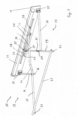
- FIG. 1 shows a schematic representation of an articulated arm awning 10 with the features of the invention in a perspective representation.
- the articulated arm awning 10 has two articulated arms 12, 13 arranged on a base 11.
- the base 11 is in the form of a metal plate for attachment to a wall or to a ceiling by means of brackets not shown in the figure.
- the device shown is a cassette awning, with the cassette serving as a cover not being shown in the figure.
- the articulated arm 12 has a support arm 14 and a drop arm 15 which are connected to one another by means of a pivot bearing 16 .
- the support arm On the base side, the support arm is attached to the base 11 by means of a pivot bearing 17 .
- the support arm 14 is connected in an articulated manner to the extension arm 15 by means of the pivot bearing 16 in a central region of the extension arm.
- the articulated arm 13 also has a support arm 18 and a drop arm 19 which are connected to one another in an articulated manner by means of a pivot bearing 20 .
- the support arm 18 is also pivotally attached to the base 11 by means of a pivot bearing 21.
- the support arm 18 is pivotally connected by means of the pivot bearing 20 to a middle region of the extension arm 19.
- a head beam 22 can also be seen, which is pivotally connected by means of pivot bearings 23, 24 to the ends of the extension arms 15, 19 facing away from the base 11.
- the extension arm 15 is connected in an articulated manner by means of a pivot bearing 25 to a carriage 26 which is guided on a rail 27 in a displaceable manner.
- the rail 27 runs parallel to the longitudinal direction of the base 11. In the installed state, the rail 27 is aligned approximately horizontally.
- a biasing means is also shown in the figure, viz.
- the gas tension spring 28 is connected to the carriage 26 with its end facing away from the bearing 29 .
- the gas tension spring 28 causes a tensile force on the carriage 26, which is directed to the bearing 29 in the figure, ie to the left in the figure.
- the gas tension spring 28 serves to pretension the extension arm 15 in its extension direction shown in the figure, ie to tension the flat covering, not shown in the figure.
- the extension arm 19 is pivotally guided by means of a pivot bearing 30 on a carriage 31, which in turn along the Longitudinal direction of the rail 27 is slidably guided.
- a gas spring 32 is fixed by a bearing 33 to the base.
- the end of the pneumatic tension spring 32 facing away from the bearing 33 is arranged on the carriage 31 .
- the gas tension spring 32 pulls the end of the extension arm 19 on the base side by means of the carriage 31 guided on the rail 27 in the direction of extension for tensioning the flat covering (not shown in the figure), in the figure along the longitudinal direction of the rail 27 to the right.
- extension arms 15, 19 cross each other to achieve the extension shown in the figure, the extension arms 15, 19 have a bend 34, 35 in their respective middle area.
- a roll of cloth 36 is arranged on the base 11 .
- the cloth roll 36 serves to accommodate the flat covering, not shown in the figure, which is stretched between the head beam 22 and the cloth roll 36 .
- a drive for the cloth roll 36 can be a motor or a hand crank drive.
- FIG 2 shows an illustration of the articulated arm awning 10 from FIG 1 in an extended position.
- the head beam 22 is extended to its maximum extended position.
- the ends of the extension arms 15, 19 on the base side are also shifted towards one another by moving the carriages 26, 31 towards one another into their extension position.
- the gas springs 28, 32 are fully retracted in the state shown.
- the advantage of using gas tension springs 28, 32 is that their tensile force in this maximally retracted state is largely equal to the tensile force in other, extended states.
- FIG. 3 shows a representation of the articulated arm awning 10 similar 2 in a largely retracted position.
- the gas tension springs 28, 32 are stretched to their largely greatest length extent for this purpose.
- the carriages 26, 31 are located substantially at opposite ends of the rail 27.
- the cranks 34, 35 are positioned adjacent one another and the spacing between the head beam 22 and the base 11 is minimal.
- FIG. 4 shows a schematic plan view of an articulated arm awning 37 as a further embodiment of the invention.
- the articulated arm awning 37 essentially corresponds to the articulated arm awning 10.
- the same elements have the same reference numbers.
- the articulated arm awning 37 has extension arms 38, 39 similar to the extension arms 15, 19.
- the bends 34, 35 of the extension arms 38, 39 are located at the Extension arms 38, 39, however, in a section between the pivot bearings 16, 17 and the head beam 22 of the extension arms 38, 39.
- figure 5 shows an enlarged view of detail A of FIG 4 .
- the carriage 26 is arranged to be displaceable on the rail 40 in the longitudinal direction thereof.
- the gas tension spring 32 of the articulated arm awning 37 is connected to the carriage 26 by means of a roller 41 with a cable 42 via rollers 43.
- the figure also shows the mode of operation of the cable 42 in combination with the gas tension spring 32 and the rollers 41, 43.
- the roller 41 is movable with the gas spring 32 and is thus arranged to be displaceable parallel to the longitudinal direction of the gas spring 32 in the figure.
- the cable 42 runs from the carriage 26 via rollers 43 for deflection to the roller 41.
- the rollers 43 are arranged in a fixed manner, while the roller 41, as already explained above, can be moved by the gas tension spring 32.
- the cable 42 then runs from the movable roller 41 to a fixed bearing 45, one end of the cable 42 on the bearing side being resilient. It is a so-called dynamic cable 44, which can provide a relatively large spring force.
- a similar arrangement is provided for the arrangement of the gas tension spring 26 . In this way, a significantly larger range of movement of the carriage 26 can be brought about by means of a relatively small stroke of the gas tension springs 28, 32 because of the deflection via the movable roller 41.
- this applies to the extension of the articulated arm awning 37.
- this also applies to the deflection of the respective extension arm 38, 39 against excessive wind pressure.
- further deflection against excessive wind pressure can also be supported by the dynamic cable 44 .
- this dynamic cable 44 compensates for the inertia of the gas tension spring 32, so that the cable 42 remains taut even when the load changes dynamically. This design is advantageous because stable gas tension springs 28, 32 are disproportionately more expensive to produce for a large stroke and thus represent a significant cost factor. An increase in the spring force with the same stroke has almost no impact.
- FIG. 6 shows an enlarged representation of detail B of 4 .
- the transition area of the head bar 22 to the extension arm 39 is shown. The same applies to the extension arm 38 .
- the pivot bearing 24 is displaceably guided in a slot 46 arranged at the end in the head beam 22 .
- a spring 47 is arranged in the elongated hole, in the exemplary embodiment shown a helical spring 47 designed as a compression spring. Also by means of this arrangement, the spring 47 effects a bias into the position shown. At the same time, the possibility of evading the spring tension when a certain wind pressure is exceeded is made possible.
- This construction also allows or supports an evasion against the wind pressure to achieve greater stability and to avoid hitting or the formation of rain bags in the articulated arm awning 37. This construction detail supports an evasion against the wind pressure and compensates for the resulting tension in the joints and arms, caused by asymmetries.
Landscapes
- Engineering & Computer Science (AREA)
- Architecture (AREA)
- Civil Engineering (AREA)
- Structural Engineering (AREA)
- Building Awnings And Sunshades (AREA)
Abstract
Description
- Die Erfindung betrifft eine Gelenkarmmarkise mit einer an einer Basis befestigbaren Tuchrolle zum Aufwickeln und Abwickeln einer flexiblen flächigen Bespannung und mindestens zwei voneinander abgewandten Enden der Tuchrolle zugeordneten Gelenkarmen zum Tragen eines Kopfbalkens, die jeweils einen an der Basis schwenkbar gelagerten Tragarm und einen gelenkig damit verbundenen Ausfallarm haben, wobei mindestens ein Ausfallarm in einem mittleren Bereich gelenkig mit einem von der Basis abgewandten Ende des zugehörigen Tragarmes verbunden ist, und ein basisseitiges Ende des mindestens einen Ausfallarmes verschiebbar mit mindestens einer zu der Tuchrolle parallelen Komponente an der Basis geführt ist.
- Derartige Gelenkarmmarkisen werden vielfach verwendet. Sie haben eine gute Stabilität, sind verhältnismäßig einfach in der Konstruktion und platzsparend und variabel an den jeweiligen Einsatzzweck anzupassen. Allerdings sind derartige Gelenkarmmarkisen nicht besonders widerstandsfähig gegen Windbelastung. Die flächige Bespannung, in der Regel ein Tuch, hat eine relativ große Angriffsfläche gegen Wind, was bereits ab verhältnismäßig geringen Windstärken eine hohe Belastung der Gelenkarme und ein unerwünschtes Schlagen der Bespannung zur Folge hat. Grundsätzlich kann die Belastbarkeit der Gelenkarmmarkise gegen Windbelastung zwar durch eine stabilere Ausführung verbessert werden. Dies führt jedoch zu einer schweren und weniger ästhetischen Ausgestaltung.
- Aus der Druckschrift
US 1,749,197 A ist eine Gelenkarmmarkise bekannt, bei der die Tragarme federnd in ihre Ausfallposition vorgespannt sind. Hierdurch wird zwar eine gewisse Verbesserung der Tuchspannung erreicht. Jedoch werden die vorstehend genannten allgemeinen Probleme bei Gelenkarmmarkisen in Bezug auf Windbelastung nicht zufriedenstellend gelöst. - Eine andere Lösung zur Verbesserung der Stabilität von Gelenkarmmarkisen schlägt die Druckschrift
US 1,594,643 A vor. Bei dieser Ausgestaltung sind die Ausfallarme bis zu der Basis verlängert. Auf diese Weise lässt sich zwar die Stabilität der Gelenkarme erhöhen. Das Flattern bei wechselnden Windbelastungen, sowie das Bilden von Regensäcken bei Verwendung der Gelenkarmmarkisen bei Regen, lässt sich auf diese Weise jedoch noch immer nicht zuverlässig verhindern. - Das der Erfindung zugrundeliegende Problem ist deshalb, eine Gelenkarmmarkise dahingehend zu verbessern, dass eine verbesserte Widerstandsfähigkeit gegen wechselnde Windbelastungen erhalten und insbesondere das Flattern und Bilden von Regensäcken der Bespannung reduziert oder möglichst vermieden werden kann.
- Bei einer Gelenkarmmarkise der vorstehend genannten Art wird das der Erfindung zugrundeliegende Problem dadurch gelöst, dass Vorspannmittel vorgesehen sind, mittels derer mindestens ein Ausfallarm mindestens in einer ausgefahrenen Position in Ausfallrichtung vorgespannt ist.
- Auf diese Weise wird mit geringem Materialaufwand eine stabilere Ausführung erzielt. Die basisseitige Führung des Ausfallarmes ermöglicht eine weitere Lagerung an der Basis, so dass höhere Kräfte aufgenommen werden können. Durch die Vorspannmittel wiederum kann bei wechselnden Windbelastungen der Ausfallarm gegen die Vorspannmittel der Windkraft ausweichen. Gleichzeitig verbleibt eine ausreichende Tuchspannung, so dass ein Flattern verhindert wird. Bei Verwendung der Gelenkarmmarkise nach der Erfindung gegen Regen wird durch das konstante Aufrechterhalten ausreichender Tuchspannung dem Bilden von Regensäcken wirksam entgegengewirkt.
- Auf diese Weise kann die Verwendung der erfindungsgemäßen Gelenkarmmarkise insbesondere in windreicheren Gebieten oder auf Kreuzfahrtschiffen ermöglicht werden. Eine besonders hochwertige und langlebige Ausbildung ergibt sich, wenn als Material Edelstahl verwendet wird. Dies kann beispielsweise polierter oder gebürsteter V4A Edelstahl in Marinequalität sein.
- Eine vorteilhafte Ausgestaltung ergibt sich dadurch, dass beide, insbesondere alle Ausfallarme an ihrem basisseitigen Ende verschiebbar an der Basis geführt sind, vorzugsweise mittels einer Schiebeführung, die insbesondere eine bevorzugt gemeinsame Schiene und einen als Gleitlager ausgebildeten Schlitten hat, der besonders bevorzugt ein Schwenklager für den Ausfallarm hat, und insbesondere gegen die Vorspannmittel verschiebbar ist. Dies ergibt einen einfachen Aufbau. Abhängig von dem gewünschten Ausfall und der Größe der Gelenkarmmarkise können mehrere Gelenkarme verwendet werden. Diese können teilweise oder alle mit einem an der Basis verschiebbar geführten Ausfallarm versehen sein. Abhängig von dem Ausfall kann für einen geringen Ausfall eine gemeinsame Schiene für den Schlitten dienen. Bei großem Ausfall sind auch mehrere Schienen an der Basis möglich. Da in diesem Fall die Ausfallarme sich bei bestimmten Betriebsbedingungen überkreuzen, bietet sich in diesem Fall eine gekröpfte Ausführung der Ausfallarme an.
- Eine andere Weiterbildung zeichnet sich dadurch aus, dass die Vorspannmittel zwischen Ausfallarm und Basis angeordnet sind, insbesondere zwischen dem basisseitigen Ende des Ausfallarmes und der Basis. Auf diese Weise ergibt sich eine einfache und gleichzeitig stabile Ausführung. Insbesondere ist der hier zur Verfügung stehende Raum unkritisch und bietet auch einem großen Hub der Vorspannmittel Platz.
- Zusätzlich oder alternativ ist es auch möglich, dass die Vorspannmittel zwischen zwei Ausfallarmen, insbesondere deren basisseitigen Enden, angeordnet sind. Ein Ausweichen gegen zu große Windlasten ist auch in diesem Fall möglich, wobei gleichzeitig Material eingespart werden kann.
- Bei einer weiteren Ausführungsform ist es von Vorteil, dass die Ausfallarme an ihren, von den basisseitigen Enden abgewandten Enden, insbesondere gelenkig, mit dem Kopfbalken verbunden sind. Dies ergibt eine einfache und zweckdienliche Lagerung des Kopfbalkens an den Gelenkarmen. Es ist dabei außerdem von Vorteil, wenn die Vorspannmittel zwischen den Ausfallarmen und dem Kopfbalken angeordnet sind. Auch hierdurch ergibt sich zum einen die Möglichkeit, einem zu großen Winddruck auszuweichen, ohne dass dabei die Tuchspannung verloren geht. Andererseits kann die Konstruktion so Spannungen auf Grund sich ausbildender Unsymmetrien, beispielsweise durch seitlichen Winddruck, ausweichen. Besonders bevorzugt ist dabei eine Schiebeführung, insbesondere in Form eines Langloches vorgesehen, in dem die Vorspannmittel angeordnet sind. Eine solche Konstruktion ist einfach, langlebig, stabil und dauerhaft herzustellen.
- Eine andere Weiterbildung der Erfindung zeichnet sich dadurch aus, dass die Vorspannmittel direkt oder indirekt mit dem Ausfallarm verbunden sind, insbesondere mittels eines, vorzugsweise umgelenkten, seilartigen langgestreckten Verbindungsmittels, wobei besonders bevorzugt die bewegliche Umlenkung, insbesondere Rolle, besonders bevorzugt nach Art eines Flaschenzuges mit einem Ende der Vorspannmittel verbunden ist. Auf diese Weise wird eine größere Freiheit hinsichtlich der Anordnung der Vorspannmittel erzielt. Gleichzeitig können mit der beweglichen Umlenkung Vorspannmittel mit verhältnismäßig geringem Hub verwendet werden, wobei gleichzeitig ein großer Ausweichweg wegen des Prinzips des Flaschenzuges für den Ausfallarm gewährleistet wird. Da Vorspannmittel mit großem Hub relativ aufwendig in ihrer Herstellung sind, wird dadurch die Herstellung der erfindungsgemäßen Gelenkarmmarkise einfach und kostengünstig möglich.
- Es ist weiter von Vorteil, dass die Vorspannmittel eine Feder, insbesondere Gasdruckfeder oder Gaszugfeder, und/oder ein, insbesondere elastisches, seilartiges Zugelement haben. Gasdruckfedern oder Gaszugfedern sind langlebig und verschleißarm. Alternativ oder zusätzlich kann das Vorsehen eines elastischen, seilartigen Zugelementes, insbesondere eines so genannten dynamischen Seiles, wie es beispielsweise vom Bergsteigen her bekannt ist, ein Ausweichen des Ausfallarmes gegen die erzeugte Vorspannkraft unterstützen oder allein bewirken.
- Es ist weiter von Vorteil, wenn die Tuchrolle antreibbar ist, insbesondere motorisch oder mittels einer Handkurbel. Auf diese Weise ist das Ausfahren und Einfahren der Gelenkarmmarkise besonders einfach.
- Nachfolgend werden Ausführungsbeispiele der Erfindung anhand der Zeichnungen näher erläutert. Es zeigen:
- Fig. 1
- eine schematische Darstellung einer Gelenkarmmarkise mit den Erfindungsmerkmalen in perspektivischer Darstellung,
- Fig. 2
- eine Darstellung der Gelenkarmmarkise von
Fig. 1 in einer ausgefahrenen Position, - Fig. 3
- eine Darstellung ähnlich
Fig. 2 in einer weitgehend eingefahrenen Position, - Fig. 4
- eine schematische Draufsicht auf ein weiteres Ausführungsbeispiel der Erfindung,
- Fig. 5
- eine vergrößerte Darstellung des Details A von
Fig. 4 , und - Fig. 6
- eine vergrößerte Darstellung von Detail B von
Fig. 4 . -
Fig. 1 zeigt eine schematische Darstellung einer Gelenkarmmarkise 10 mit den Erfindungsmerkmalen in perspektivischer Darstellung. Die Gelenkarmmarkise 10 hat zwei an einer Basis 11 angeordnete Gelenkarme 12, 13. Die Basis 11 ist hierbei als Metallplatte zum Anbringen an einer Wand oder mittels nicht in der Figur gezeigter Träger an einer Decke. Bei der gezeigten Vorrichtung handelt es sich um eine Kassettenmarkise, wobei die als Abdeckung dienende Kassette nicht in der Figur dargestellt ist. - Wie sich der Figur entnehmen lässt, hat der Gelenkarm 12 einen Tragarm 14 und einen Ausfallarm 15, die mittels eines Schwenklagers 16 miteinander verbunden sind. Basisseitig ist der Tragarm mittels eines Schwenklagers 17 an der Basis 11 befestigt. An seinem von der Basis abgewandten Ende ist der Tragarm 14 mittels des Schwenklagers 16 in einem mittleren Bereich des Ausfallarmes 15 mit diesem gelenkig verbunden.
- Auf ähnliche Weise weist auch der Gelenkarm 13 einen Tragarm 18 und einen Ausfallarm 19 auf, die mittels eines Schwenklagers 20 gelenkig miteinander verbunden sind. Ähnlich dem Tragarm 14 ist auch der Tragarm 18 mittels eines Schwenklagers 21 an der Basis 11 schwenkbar befestigt. An seinem von der Basis 11 abgewandten Ende ist der Tragarm 18 mittels des Schwenklagers 20 mit einem mittleren Bereich des Ausfallarmes 19 schwenkbar verbunden.
- Es ist weiter ein Kopfbalken 22 zu sehen, der mittels Schwenklager 23, 24 jeweils mit den von der Basis 11 abgewandten Enden der Ausfallarme 15, 19 schwenkbar verbunden ist.
- Basisseitig ist der Ausfallarm 15 mittels eines Schwenklagers 25 mit einem Schlitten 26 gelenkig verbunden, der verschiebbar an einer Schiene 27 geführt ist. Die Schiene 27 verläuft parallel zur Längsrichtung der Basis 11. Im montierten Zustand ist die Schiene 27 etwa horizontal ausgerichtet.
- Es ist außerdem ein Vorspannmittel, nämlich eine Gaszugfeder 28 in der Figur gezeigt, die an einem Ende mit einem Lager 29 an der Basis 11 befestigt ist. Mit ihrem von dem Lager 29 abgewandten Ende ist die Gaszugfeder 28 mit dem Schlitten 26 verbunden. Auf diese Weise bewirkt die Gaszugfeder 28 eine Zugkraft auf den Schlitten 26, die in der Figur zu dem Lager 29 also in der Figur nach links gerichtet ist. Auf diese Weise dient die Gaszugfeder 28 zum Vorspannen des Ausfallarmes 15 in seine in der Figur dargestellte Ausfallrichtung, also zum Spannen der nicht in der Figur dargestellten flächigen Bespannung.
- Auf ähnliche Weise ist auch der Ausfallarm 19 mittels eines Schwenklagers 30 schwenkbar an einem Schlitten 31 geführt, der wiederum entlang der Längserstreckungsrichtung der Schiene 27 verschiebbar geführt ist. Ähnlich der Gaszugfeder 28 ist eine Gaszugfeder 32 mittels eines Lagers 33 an der Basis befestigt. Das von dem Lager 33 abgewandte Ende der Gaszugfeder 32 ist an dem Schlitten 31 angeordnet. Auf diese Weise zieht die Gaszugfeder 32 das basisseitige Ende des Ausfallarmes 19 mittels des an der Schiene 27 geführten Schlittens 31 in Ausfallrichtung zum Spannen der nicht in der Figur dargestellten flächigen Bespannung, in der Figur entlang der Längsrichtung der Schiene 27 nach rechts.
- Da sich die Ausfallarme 15, 19 zum Erzielen des in der Figur dargestellten Ausfalls überkreuzen, weisen die Ausfallarme 15, 19 in ihrem jeweiligen mittleren Bereich eine Kröpfung 34, 35 auf.
- Der Figur ist außerdem zu entnehmen, dass eine Tuchrolle 36 an der Basis 11 angeordnet ist. Die Tuchrolle 36 dient zum Aufnehmen der nicht in der Figur dargestellten flächigen Bespannung, die zwischen dem Kopfbalken 22 und der Tuchrolle 36 gespannt ist. Nicht in der Figur dargestellt ist außerdem ein Antrieb für die Tuchrolle 36. Es kann sich bei diesem Antrieb um einen Motor oder um einen Handkurbelantrieb handeln.
-
Fig. 2 zeigt eine Darstellung der Gelenkarmmarkise 10 vonFig. 1 in einer ausgefahrenen Position. Wie sich der Figur entnehmen lässt, ist der Kopfbalken 22 in seine maximal ausgefahrene Position ausgefahren. Dazu sind die basisseitigen Enden der Ausfallarme 15, 19 mittels Verschieben der Schlitten 26, 31 zueinander hin ebenfalls in ihre Ausfallposition verschoben. Die Gaszugfedern 28, 32 sind in dem gezeigten Zustand maximal eingefahren. Der Vorteil der Verwendung von Gaszugfedern 28, 32 ist hierbei, dass ihre Zugkraft in diesem maximal eingefahrenen Zustand weitgehend gleich der Zugkraft in anderen, ausgefahrenen Zuständen ist. -
Fig. 3 zeigt eine Darstellung der Gelenkarmmarkise 10 ähnlichFig. 2 in einer weitgehend eingefahrenen Position. Wie sich der Figur entnehmen lässt, sind die Gaszugfedern 28, 32 hierzu auf ihre weitgehend größte Längenausdehnung gestreckt. Die Schlitten 26, 31 befinden sich im Wesentlichen an voneinander abgewandten Enden der Schiene 27. Die Kröpfungen 34, 35 kommen benachbart zueinander zu liegen und der Abstand zwischen dem Kopfbalken 22 und der Basis 11 ist minimal. -
Fig. 4 zeigt eine schematische Draufsicht auf eine Gelenkarmmarkise 37 als ein weiteres Ausführungsbeispiel der Erfindung. Die Gelenkarmmarkise 37 entspricht im Wesentlichen der Gelenkarmmarkise 10. Gleiche Elemente tragen die gleichen Bezugszeichen. Abweichend von der Gelenkarmmarkise 10 hat die Gelenkarmmarkise 37 Ausfallarme 38, 39 ähnlich der Ausfallarme 15, 19. Die Kröpfungen 34, 35 der Ausfallarme 38, 39 befinden sich zum Erzielen eines größeren Ausfalls bei den Ausfallarmen 38, 39 jedoch in einem Abschnitt zwischen den Schwenklagern 16, 17 und dem Kopfbalken 22 der Ausfallarme 38, 39. - Ein weiterer Unterschied zwischen der Gelenkarmmarkise 37 und der Gelenkarmmarkise 10 betrifft die Ausgestaltung einer Schiene 40 ähnlich der Schiene 27, sowie die Anordnung der Gaszugfedern 28, 32, auf die nachfolgend anhand
Fig. 5 noch Bezug genommen wird. -
Fig. 5 zeigt eine vergrößerte Darstellung des Details A vonFig. 4 . Wie sich der Figur entnehmen lässt, ist der Schlitten 26 in Längsrichtung der Schiene 40 an dieser verschiebbar angeordnet. - Anders als bei der Gelenkarmmarkise 10 ist bei der Gelenkarmmarkise 37 die Gaszugfeder 32 mittels einer Rolle 41 mit einem Seil 42 über Rollen 43 mit dem Schlitten 26 verbunden. Schematisch in der Figur dargestellt ist zu einem besseren Verständnis zusätzlich die Wirkungsweise des Seiles 42 in Kombination mit der Gaszugfeder 32 und den Rollen 41, 43.
- Wie bereits beschrieben, ist die Rolle 41 mit der Gaszugfeder 32 und damit bewegbar, in der Figur parallel zur Längsrichtung der Gaszugfeder 32 verschiebbar angeordnet. Das Seil 42 verläuft von dem Schlitten 26 über Rollen 43 zur Umlenkung zu der Rolle 41. Die Rollen 43 sind dabei feststehend angeordnet, während die Rolle 41, wie vorstehend bereits erläutert, von der Gaszugfeder 32 bewegt werden kann.
- Von der beweglichen Rolle 41 verläuft das Seil 42 dann zu einem festen Lager 45, wobei ein lagerseitiges Ende des Seiles 42 federnd ausgebildet ist. Es handelt sich dabei um ein sogenanntes dynamisches Seil 44, das eine verhältnismäßig große Federkraft bereitstellen kann. Für die Anordnung der Gaszugfeder 26 ist eine ähnliche Anordnung vorgesehen. Auf diese Weise lässt sich mittels eines verhältnismäßig geringen Hubes der Gaszugfedern 28, 32 wegen der Umlenkung über die bewegliche Rolle 41 ein deutlich größerer Bewegungsbereich des Schlittens 26 bewirken.
- Dies gilt zum einen für das Ausfahren der Gelenkarmmarkise 37. Zum anderen aber auch für das Ausweichen des jeweiligen Ausfallarmes 38, 39 gegen einen zu großen Winddruck. Gleichzeitig kann ein weiteres Einfedern gegen zu großen Winddruck auch von dem dynamischen Seil 44 unterstützt werden. Außerdem gleicht dieses dynamische Seil 44 die Trägheit der Gaszugfeder 32 aus, so dass das Seil 42 auch bei dynamischem Lastwechsel gespannt bleibt. Diese Konstruktion ist deshalb von Vorteil, weil stabile Gaszugfedern 28, 32 bei einem großen erzielten Hub unverhältnismäßig viel aufwendiger zu produzieren sind und somit einen erheblichen Kostenfaktor darstellen. Eine Erhöhung der Federkraft bei gleichem Hub schlägt dabei nahezu nicht zu Buche.
-
Fig. 6 zeigt eine vergrößerte Darstellung von Detail B vonFig. 4 . Gezeigt ist der Übergangsbereich des Kopfbalkens 22 zu dem Ausfallarm 39. In Bezug auf den Ausfallarm 38 gilt entsprechendes. - Wie sich der Figur entnehmen lässt, ist das Schwenklager 24 bei dem gezeigten Ausführungsbeispiel in einem endseitig in dem Kopfbalken 22 angeordneten Langloch 46 verschiebbar geführt. Gleichermaßen ist in dem Langloch eine Feder 47, bei dem gezeigten Ausführungsbeispiel eine als Druckfeder ausgebildete Schraubenfeder 47 angeordnet. Auch mittels dieser Anordnung bewirkt die Feder 47 eine Vorspannung in die gezeigte Position. Gleichzeitig wird die Möglichkeit eines Ausweichens gegen die Federspannung bei Überschreiten eines bestimmten Winddruckes ermöglicht. Auch diese Konstruktion ermöglicht oder unterstützt ein Ausweichen gegen den Winddruck zum Erzielen einer höheren Stabilität und zum Vermeiden des Schlagens oder des Bildens von Regensäcken bei der Gelenkarmmarkise 37. Dieses Konstruktionsdetail unterstützt ein Ausweichen gegen den Winddruck und kompensiert dadurch entstehende Spannungen in den Gelenken und Armen, die durch Unsymmetrien verursacht werden.
-
- 10
- Gelenkarmmarkise
- 11
- Basis
- 12
- Gelenkarm
- 13
- Gelenkarm
- 14
- Tragarm
- 15
- Ausfallarm
- 16
- Schwenklager
- 17
- Schwenklager
- 18
- Tragarm
- 19
- Ausfallarm
- 20
- Schwenklager
- 21
- Schwenklager
- 22
- Kopfbalken
- 23
- Schwenklager
- 24
- Schwenklager
- 25
- Schwenklager
- 26
- Schlitten
- 27
- Schiene
- 28
- Gaszugfeder
- 29
- Lager
- 30
- Schwenklager
- 31
- Schlitten
- 32
- Gaszugfeder
- 33
- Lager
- 34
- Kröpfung
- 35
- Kröpfung
- 36
- Tuchrolle
- 37
- Gelenkarmmarkise
- 38
- Ausfallarm
- 39
- Ausfallarm
- 40
- Schiene
- 41
- Rolle
- 42
- Seil
- 43
- Rolle
- 44
- Dynamisches Seil
- 45
- Lager
- 46
- Langloch
- 47
- Feder
Claims (8)
- Gelenkarmmarkise mit einer an einer Basis (11) befestigbaren Tuchrolle (36) zum Aufwickeln und Abwickeln einer flexiblen flächigen Bespannung und mindestens zwei voneinander abgewandten Enden der Tuchrolle zugeordneten Gelenkarmen (12, 13) zum Tragen eines Kopfbalkens (22), die jeweils einen an der Basis schwenkbar gelagerten Tragarm (14, 18) und einen gelenkig damit verbundenen Ausfallarm (15, 19, 38, 39) haben, wobei mindestens ein Ausfallarm (15, 19, 38, 39) in einem mittleren Bereich gelenkig mit einem von der Basis (11) abgewandten Ende des zugehörigen Tragarmes (14, 18) verbunden ist, und ein basisseitiges Ende des mindestens einen Ausfallarmes (15, 19) verschiebbar mit mindestens einer zu der Tuchrolle (36) parallelen Komponente an der Basis (11) geführt ist, dadurch gekennzeichnet, dass Vorspannmittel (28, 32, 44, 47) vorgesehen sind, mittels derer mindestens ein Ausfallarm (15, 19, 38, 39) mindestens in einer ausgefahrenen Position in Ausfallrichtung vorgespannt ist.
- Gelenkarmmarkise nach Anspruch 1, dadurch gekennzeichnet, dass beide, insbesondere alle Ausfallarme (15, 19, 38, 39) an ihrem basisseitigen Ende verschiebbar an der Basis (11) geführt sind, vorzugsweise mittels einer Schiebeführung, die insbesondere eine, bevorzugt gemeinsamen Schiene (27, 40) und einen als Gleitlager ausgebildeten Schlitten (26, 31), hat der besonders bevorzugt ein Schwenklager (25, 30) für den Ausfallarm (15, 19, 38, 39) hat und insbesondere gegen die Vorspannmittel (28, 32, 44, 47) verschiebbar ist.
- Gelenkarmmarkise nach Anspruch 1 oder 2, dadurch gekennzeichnet, dass die Vorspannmittel (28, 32, 44) zwischen Ausfallarm (15, 19) und Basis (11) angeordnet sind, insbesondere zwischen dem basisseitigen Ende des Ausfallarmes (15, 19, 38, 39) und der Basis (11).
- Gelenkarmmarkise nach einem der vorhergehenden Ansprüche, dadurch gekennzeichnet, dass die Vorspannmittel (28, 32, 44) zwischen zwei Ausfallarmen (15, 19, 38, 39), insbesondere deren basisseitigen Enden, angeordnet sind.
- Gelenkarmmarkise nach einem der vorhergehenden Ansprüche, dadurch gekennzeichnet, dass die Ausfallarme (15, 19, 38, 39) an ihren, von den basisseitigen Enden abgewandten Enden, insbesondere gelenkig, mit dem Kopfbalken (22) verbunden sind, wobei vorzugsweise die Vorspannmittel (47) zwischen den Ausfallarmen (15, 19, 38, 39) und dem Kopfbalken (22) angeordnet sind, der besonders bevorzugt eine Schiebeführung, insbesondere in Form eines Langloches (46), hat, in dem die Vorspannmittel (47) angeordnet sind.
- Gelenkarmmarkise nach einem der vorhergehenden Ansprüche, dadurch gekennzeichnet, dass die Vorspannmittel (28, 32, 44, 47) direkt oder indirekt mit dem Ausfallarm (15, 19, 38, 39) verbunden sind, insbesondere mittels eines, vorzugsweise umgelenkten, seilartigen langgesteckten Verbindungsmittels (42), wobei besonders bevorzugt eine bewegliche Umlenkung, insbesondere Rolle (43), besonders bevorzugt nach Art eines Flaschenzuges mit einem Ende der Vorspannmittel (28, 32) verbunden ist.
- Gelenkarmmarkise nach einem der vorhergehenden Ansprüche, dadurch gekennzeichnet, dass die Vorspannmittel eine Feder (47), insbesondere Gasdruckfeder oder Gaszugfeder (28, 32), und/oder ein, insbesondere elastisches, seilartiges Zugelement (44) haben.
- Gelenkarmmarkise nach einem der vorhergehenden Ansprüche, dadurch gekennzeichnet, dass die Tuchrolle (36) antreibbar ist, insbesondere motorisch oder mittels einer Handkurbel.
Applications Claiming Priority (1)
| Application Number | Priority Date | Filing Date | Title |
|---|---|---|---|
| DE102021124027.1A DE102021124027B3 (de) | 2021-09-16 | 2021-09-16 | Gelenkarmmarkise |
Publications (3)
| Publication Number | Publication Date |
|---|---|
| EP4151813A1 true EP4151813A1 (de) | 2023-03-22 |
| EP4151813C0 EP4151813C0 (de) | 2024-11-06 |
| EP4151813B1 EP4151813B1 (de) | 2024-11-06 |
Family
ID=83115025
Family Applications (1)
| Application Number | Title | Priority Date | Filing Date |
|---|---|---|---|
| EP22195426.6A Active EP4151813B1 (de) | 2021-09-16 | 2022-09-13 | Gelenkarmmarkise |
Country Status (2)
| Country | Link |
|---|---|
| EP (1) | EP4151813B1 (de) |
| DE (1) | DE102021124027B3 (de) |
Citations (6)
| Publication number | Priority date | Publication date | Assignee | Title |
|---|---|---|---|---|
| GB208575A (en) * | 1922-08-16 | 1923-12-17 | Edward Chismon Golding | Improvements in sunblinds and the like |
| US1594643A (en) | 1924-10-01 | 1926-08-03 | Stuart John Lenard | Awning |
| US1749197A (en) | 1929-01-26 | 1930-03-04 | Stuart John Lenard | Awning |
| US1915944A (en) * | 1931-04-16 | 1933-06-27 | Robert Forgie Hunter | Projection screen |
| DE7804978U1 (de) * | 1978-02-20 | 1978-06-08 | Holl, Josef, 7900 Ulm | Freitragende markise |
| US6457508B1 (en) * | 1998-03-26 | 2002-10-01 | Sanwa Shutter Corporation | Sunshade roll screen |
Family Cites Families (1)
| Publication number | Priority date | Publication date | Assignee | Title |
|---|---|---|---|---|
| FR455596A (fr) | 1913-03-15 | 1913-08-04 | Belzacq Freres Soc | Store |
-
2021
- 2021-09-16 DE DE102021124027.1A patent/DE102021124027B3/de active Active
-
2022
- 2022-09-13 EP EP22195426.6A patent/EP4151813B1/de active Active
Patent Citations (6)
| Publication number | Priority date | Publication date | Assignee | Title |
|---|---|---|---|---|
| GB208575A (en) * | 1922-08-16 | 1923-12-17 | Edward Chismon Golding | Improvements in sunblinds and the like |
| US1594643A (en) | 1924-10-01 | 1926-08-03 | Stuart John Lenard | Awning |
| US1749197A (en) | 1929-01-26 | 1930-03-04 | Stuart John Lenard | Awning |
| US1915944A (en) * | 1931-04-16 | 1933-06-27 | Robert Forgie Hunter | Projection screen |
| DE7804978U1 (de) * | 1978-02-20 | 1978-06-08 | Holl, Josef, 7900 Ulm | Freitragende markise |
| US6457508B1 (en) * | 1998-03-26 | 2002-10-01 | Sanwa Shutter Corporation | Sunshade roll screen |
Also Published As
| Publication number | Publication date |
|---|---|
| EP4151813C0 (de) | 2024-11-06 |
| EP4151813B1 (de) | 2024-11-06 |
| DE102021124027B3 (de) | 2022-09-22 |
Similar Documents
| Publication | Publication Date | Title |
|---|---|---|
| DE60120299T2 (de) | Seilanordnung für einen Turmkran | |
| EP0731040B1 (de) | Knickbares Förderband mit definierter Spannung des Tragorgans | |
| EP0334187A1 (de) | Fahrzeugkran mit Teleskopausleger | |
| CH651739A5 (de) | Vorrichtung zum verstellen der winkellage einer schwenkbeweglichen stuetzflaeche. | |
| DE2640447C3 (de) | Vorrichtung zum gewichtsentlasteten Halten eines Handschraubers | |
| DE102021124027B3 (de) | Gelenkarmmarkise | |
| WO1998043856A2 (de) | Hebevorrichtung für kraftfahrzeuge und fahrzeuganhänger, insbesondere ein wagenheber | |
| DE2743748C3 (de) | Gelenkarmmarkise | |
| DE3806621A1 (de) | Solarbeschattung | |
| EP0778379A1 (de) | Gegenzugmarkise mit mitlaufenden Federn | |
| DE8703605U1 (de) | Rollo für Automobilfenster, insbesondere für PKW-Heckscheiben | |
| DE202010004125U1 (de) | Schutzvorrichtung, insbesondere aufrollbares Sonnensegel | |
| EP0503269B1 (de) | Von aussen gehaltener Rundbreithalter | |
| WO2007124802A1 (de) | Abstellvorrichtung für kraftfahrzeuge | |
| DE10209387C1 (de) | Scherenhubtisch | |
| DE3900463A1 (de) | Gelenkarm fuer markisen od. dgl. | |
| DE202007007034U1 (de) | Wendestangenabzug für eine Schlauchfolienextrusionsanlage | |
| DE2137350A1 (de) | Zugwalzen mit gleichförmigem Druck | |
| DE3840408C2 (de) | ||
| DE69000703T2 (de) | Vorrichtung, um ein sonnenschirmtuch unter spannung zu halten, insbesondere fuer eine veranda oder pergola. | |
| EP1629942B1 (de) | Bandschleifmaschine | |
| DE102012102606B4 (de) | Vertikal bewegliche Hubbett-Vorrichtung | |
| DE3222697C2 (de) | Mobiler Schienenaufzug mit neigungsverstellbarer Teleskopschiene | |
| DE102009018246B4 (de) | Windschott für ein Cabriolet | |
| DE69718955T2 (de) | Markise |
Legal Events
| Date | Code | Title | Description |
|---|---|---|---|
| PUAI | Public reference made under article 153(3) epc to a published international application that has entered the european phase |
Free format text: ORIGINAL CODE: 0009012 |
|
| STAA | Information on the status of an ep patent application or granted ep patent |
Free format text: STATUS: THE APPLICATION HAS BEEN PUBLISHED |
|
| AK | Designated contracting states |
Kind code of ref document: A1 Designated state(s): AL AT BE BG CH CY CZ DE DK EE ES FI FR GB GR HR HU IE IS IT LI LT LU LV MC MK MT NL NO PL PT RO RS SE SI SK SM TR |
|
| STAA | Information on the status of an ep patent application or granted ep patent |
Free format text: STATUS: REQUEST FOR EXAMINATION WAS MADE |
|
| 17P | Request for examination filed |
Effective date: 20230922 |
|
| RBV | Designated contracting states (corrected) |
Designated state(s): AL AT BE BG CH CY CZ DE DK EE ES FI FR GB GR HR HU IE IS IT LI LT LU LV MC MK MT NL NO PL PT RO RS SE SI SK SM TR |
|
| GRAP | Despatch of communication of intention to grant a patent |
Free format text: ORIGINAL CODE: EPIDOSNIGR1 |
|
| STAA | Information on the status of an ep patent application or granted ep patent |
Free format text: STATUS: GRANT OF PATENT IS INTENDED |
|
| INTG | Intention to grant announced |
Effective date: 20240104 |
|
| GRAJ | Information related to disapproval of communication of intention to grant by the applicant or resumption of examination proceedings by the epo deleted |
Free format text: ORIGINAL CODE: EPIDOSDIGR1 |
|
| STAA | Information on the status of an ep patent application or granted ep patent |
Free format text: STATUS: REQUEST FOR EXAMINATION WAS MADE |
|
| GRAP | Despatch of communication of intention to grant a patent |
Free format text: ORIGINAL CODE: EPIDOSNIGR1 |
|
| STAA | Information on the status of an ep patent application or granted ep patent |
Free format text: STATUS: GRANT OF PATENT IS INTENDED |
|
| INTC | Intention to grant announced (deleted) | ||
| INTG | Intention to grant announced |
Effective date: 20240517 |
|
| GRAS | Grant fee paid |
Free format text: ORIGINAL CODE: EPIDOSNIGR3 |
|
| GRAA | (expected) grant |
Free format text: ORIGINAL CODE: 0009210 |
|
| STAA | Information on the status of an ep patent application or granted ep patent |
Free format text: STATUS: THE PATENT HAS BEEN GRANTED |
|
| AK | Designated contracting states |
Kind code of ref document: B1 Designated state(s): AL AT BE BG CH CY CZ DE DK EE ES FI FR GB GR HR HU IE IS IT LI LT LU LV MC MK MT NL NO PL PT RO RS SE SI SK SM TR |
|
| REG | Reference to a national code |
Ref country code: GB Ref legal event code: FG4D Free format text: NOT ENGLISH |
|
| REG | Reference to a national code |
Ref country code: CH Ref legal event code: EP |
|
| REG | Reference to a national code |
Ref country code: DE Ref legal event code: R096 Ref document number: 502022002062 Country of ref document: DE |
|
| REG | Reference to a national code |
Ref country code: IE Ref legal event code: FG4D Free format text: LANGUAGE OF EP DOCUMENT: GERMAN |
|
| U01 | Request for unitary effect filed |
Effective date: 20241129 |
|
| U07 | Unitary effect registered |
Designated state(s): AT BE BG DE DK EE FI FR IT LT LU LV MT NL PT RO SE SI Effective date: 20241211 |
|
| PG25 | Lapsed in a contracting state [announced via postgrant information from national office to epo] |
Ref country code: IS Free format text: LAPSE BECAUSE OF FAILURE TO SUBMIT A TRANSLATION OF THE DESCRIPTION OR TO PAY THE FEE WITHIN THE PRESCRIBED TIME-LIMIT Effective date: 20250306 Ref country code: HR Free format text: LAPSE BECAUSE OF FAILURE TO SUBMIT A TRANSLATION OF THE DESCRIPTION OR TO PAY THE FEE WITHIN THE PRESCRIBED TIME-LIMIT Effective date: 20241106 |
|
| PG25 | Lapsed in a contracting state [announced via postgrant information from national office to epo] |
Ref country code: ES Free format text: LAPSE BECAUSE OF FAILURE TO SUBMIT A TRANSLATION OF THE DESCRIPTION OR TO PAY THE FEE WITHIN THE PRESCRIBED TIME-LIMIT Effective date: 20241106 |
|
| PG25 | Lapsed in a contracting state [announced via postgrant information from national office to epo] |
Ref country code: NO Free format text: LAPSE BECAUSE OF FAILURE TO SUBMIT A TRANSLATION OF THE DESCRIPTION OR TO PAY THE FEE WITHIN THE PRESCRIBED TIME-LIMIT Effective date: 20250206 |
|
| PG25 | Lapsed in a contracting state [announced via postgrant information from national office to epo] |
Ref country code: GR Free format text: LAPSE BECAUSE OF FAILURE TO SUBMIT A TRANSLATION OF THE DESCRIPTION OR TO PAY THE FEE WITHIN THE PRESCRIBED TIME-LIMIT Effective date: 20250207 |
|
| PG25 | Lapsed in a contracting state [announced via postgrant information from national office to epo] |
Ref country code: PL Free format text: LAPSE BECAUSE OF FAILURE TO SUBMIT A TRANSLATION OF THE DESCRIPTION OR TO PAY THE FEE WITHIN THE PRESCRIBED TIME-LIMIT Effective date: 20241106 |
|
| PG25 | Lapsed in a contracting state [announced via postgrant information from national office to epo] |
Ref country code: RS Free format text: LAPSE BECAUSE OF FAILURE TO SUBMIT A TRANSLATION OF THE DESCRIPTION OR TO PAY THE FEE WITHIN THE PRESCRIBED TIME-LIMIT Effective date: 20250206 |
|
| PG25 | Lapsed in a contracting state [announced via postgrant information from national office to epo] |
Ref country code: SM Free format text: LAPSE BECAUSE OF FAILURE TO SUBMIT A TRANSLATION OF THE DESCRIPTION OR TO PAY THE FEE WITHIN THE PRESCRIBED TIME-LIMIT Effective date: 20241106 |
|
| PG25 | Lapsed in a contracting state [announced via postgrant information from national office to epo] |
Ref country code: SK Free format text: LAPSE BECAUSE OF FAILURE TO SUBMIT A TRANSLATION OF THE DESCRIPTION OR TO PAY THE FEE WITHIN THE PRESCRIBED TIME-LIMIT Effective date: 20241106 |
|
| PG25 | Lapsed in a contracting state [announced via postgrant information from national office to epo] |
Ref country code: CZ Free format text: LAPSE BECAUSE OF FAILURE TO SUBMIT A TRANSLATION OF THE DESCRIPTION OR TO PAY THE FEE WITHIN THE PRESCRIBED TIME-LIMIT Effective date: 20241106 |
|
| PLBE | No opposition filed within time limit |
Free format text: ORIGINAL CODE: 0009261 |
|
| STAA | Information on the status of an ep patent application or granted ep patent |
Free format text: STATUS: NO OPPOSITION FILED WITHIN TIME LIMIT |
|
| REG | Reference to a national code |
Ref country code: CH Ref legal event code: U11 Free format text: ST27 STATUS EVENT CODE: U-0-0-U10-U11 (AS PROVIDED BY THE NATIONAL OFFICE) Effective date: 20251001 |
|
| 26N | No opposition filed |
Effective date: 20250807 |
|
| U20 | Renewal fee for the european patent with unitary effect paid |
Year of fee payment: 4 Effective date: 20250930 |
|
| PGFP | Annual fee paid to national office [announced via postgrant information from national office to epo] |
Ref country code: CH Payment date: 20251001 Year of fee payment: 4 |
|
| PG25 | Lapsed in a contracting state [announced via postgrant information from national office to epo] |
Ref country code: MC Free format text: LAPSE BECAUSE OF FAILURE TO SUBMIT A TRANSLATION OF THE DESCRIPTION OR TO PAY THE FEE WITHIN THE PRESCRIBED TIME-LIMIT Effective date: 20241106 |
|
| PG25 | Lapsed in a contracting state [announced via postgrant information from national office to epo] |
Ref country code: IE Free format text: LAPSE BECAUSE OF NON-PAYMENT OF DUE FEES Effective date: 20250913 |