EP4151292B1 - Einstellbarer vorderbacken - Google Patents
Einstellbarer vorderbacken Download PDFInfo
- Publication number
- EP4151292B1 EP4151292B1 EP22180093.1A EP22180093A EP4151292B1 EP 4151292 B1 EP4151292 B1 EP 4151292B1 EP 22180093 A EP22180093 A EP 22180093A EP 4151292 B1 EP4151292 B1 EP 4151292B1
- Authority
- EP
- European Patent Office
- Prior art keywords
- sole
- ski
- side wall
- housing
- front jaw
- Prior art date
- Legal status (The legal status is an assumption and is not a legal conclusion. Google has not performed a legal analysis and makes no representation as to the accuracy of the status listed.)
- Active
Links
Images




Classifications
-
- A—HUMAN NECESSITIES
- A63—SPORTS; GAMES; AMUSEMENTS
- A63C—SKATES; SKIS; ROLLER SKATES; DESIGN OR LAYOUT OF COURTS, RINKS OR THE LIKE
- A63C9/00—Ski bindings
- A63C9/08—Ski bindings yieldable or self-releasing in the event of an accident, i.e. safety bindings
- A63C9/0807—Ski bindings yieldable or self-releasing in the event of an accident, i.e. safety bindings for both towing and downhill skiing
-
- A—HUMAN NECESSITIES
- A63—SPORTS; GAMES; AMUSEMENTS
- A63C—SKATES; SKIS; ROLLER SKATES; DESIGN OR LAYOUT OF COURTS, RINKS OR THE LIKE
- A63C9/00—Ski bindings
- A63C9/005—Ski bindings with means for adjusting the position of a shoe holder or of the complete binding relative to the ski
-
- A—HUMAN NECESSITIES
- A63—SPORTS; GAMES; AMUSEMENTS
- A63C—SKATES; SKIS; ROLLER SKATES; DESIGN OR LAYOUT OF COURTS, RINKS OR THE LIKE
- A63C9/00—Ski bindings
- A63C9/08—Ski bindings yieldable or self-releasing in the event of an accident, i.e. safety bindings
- A63C9/085—Ski bindings yieldable or self-releasing in the event of an accident, i.e. safety bindings with sole hold-downs, e.g. swingable
- A63C9/08507—Ski bindings yieldable or self-releasing in the event of an accident, i.e. safety bindings with sole hold-downs, e.g. swingable with a plurality of mobile jaws
- A63C9/08521—Ski bindings yieldable or self-releasing in the event of an accident, i.e. safety bindings with sole hold-downs, e.g. swingable with a plurality of mobile jaws pivoting about a vertical axis, e.g. side release
-
- A—HUMAN NECESSITIES
- A63—SPORTS; GAMES; AMUSEMENTS
- A63C—SKATES; SKIS; ROLLER SKATES; DESIGN OR LAYOUT OF COURTS, RINKS OR THE LIKE
- A63C9/00—Ski bindings
- A63C9/08—Ski bindings yieldable or self-releasing in the event of an accident, i.e. safety bindings
- A63C9/085—Ski bindings yieldable or self-releasing in the event of an accident, i.e. safety bindings with sole hold-downs, e.g. swingable
- A63C9/08535—Ski bindings yieldable or self-releasing in the event of an accident, i.e. safety bindings with sole hold-downs, e.g. swingable with a mobile body or base or single jaw
- A63C9/08542—Ski bindings yieldable or self-releasing in the event of an accident, i.e. safety bindings with sole hold-downs, e.g. swingable with a mobile body or base or single jaw pivoting about a transversal axis
Definitions
- the invention relates to a toe piece of a ski binding with a housing, a first sole holder connected to the housing at a first pivot joint, a second sole holder connected to the housing at a second pivot joint, and a tensioning device that tensions the first sole holder and the second sole holder towards one another.
- the first sole holder has an inner first side wall and the second sole holder has an inner second side wall.
- the first inner side wall and the second inner side wall face one another with a clear horizontal distance.
- the toe piece further comprises an adjusting device for adjusting a horizontal distance between the mutually facing inner side walls.
- ski bindings compatible with different types of ski boots are also in demand among users who enjoy both off-piste skiing and downhill skiing, so-called freeriders.
- Common types of ski boots include the so-called “ski boots for piste skiing” according to DIN ISO 5355, whose specifications are regulated for both adult ski boots (Type A) and children's ski boots (Type C).
- DIN ISO 9523 regulates "touring ski boots for adults.”
- the newly added standard DIN ISO 23223 specifies "alpine ski boots with improved outsoles (known commercially as "GripWalk” soles). DIN ISO 23223 also distinguishes between adult (Type A) and children's (Type C) ski boots.
- the toe piece of a ski binding is designed so that, by adjusting the height of a contact surface for the underside of the ski boot sole or by adjusting the height of the toe piece itself, it can accommodate either a ski boot according to DIN ISO 9523 for touring or a ski boot according to DIN ISO 5355 for downhill skiing.
- ski binding toe pieces that propose height-adjustable contact plates for the front end of the ski boot sole base, in order to be able to use ski boot soles of different thicknesses in one and the same binding.
- Such a toe piece is known, for example, from AT 517430 A1 known.
- the DE 10 2012 217 867 B3 relates to a front piece of a ski binding in which a holding device for the front end of a ski boot sole can be locked in a base plate in two positions, in a first position for a ski boot with an alpine sole and in a second position for a ski boot with a touring sole.
- the object of the invention is to provide a toe piece for a ski binding that can be easily adjusted to accommodate ski boots with different ski boot soles.
- the invention further relates to a ski binding with such a toe piece. This object is achieved by claim 1.
- the toe piece for a ski binding, such as an alpine binding, a touring binding, or a freerider binding.
- the toe piece can be connected to the ski directly or via a base, or arranged together with a heel piece on a plate or frame.
- the toe piece comprises a housing, a first sole holder connected to the housing in a first pivot joint, a second sole holder connected to the housing in a second pivot joint, and a Clamping device that clamps the first sole holder and the second sole holder towards each other.
- the first sole holder has an inner first side wall
- the second sole holder has an inner second side wall.
- the first inner side wall and the second inner side wall face each other with a clear horizontal distance.
- the first sole holder of the toe piece may comprise a sole holder housing and a sole holding element with the first inner side wall.
- the second sole holder of the toe piece may comprise a sole holder housing and a sole holding element with the second inner side wall.
- the distance between different point pairs defined by the mirroring can be of different sizes.
- the sole holding element is mounted in the sole holder housing in such a way that when the horizontal distance is adjusted the side walls, the sole holding element performs a linear and/or rotational movement with respect to the sole holding housing.
- the first inner side wall and the second inner side wall preferably have a contoured surface.
- the first inner side wall and the second inner side wall can be curved in some areas, include indentations, for example, at the edge or at a corner, or be shaped in some other way.
- the first inner side wall and the second inner side wall are preferably mirror-identical with respect to a mirror plane with a mirror axis that coincides with the central longitudinal axis of the front jaw.
- the adjustment device may comprise a locking mechanism which fixes the first sole holder or the first inner side wall and the second sole holder or the second inner sole wall in a first locking position at the first distance and/or at least in a second locking position at the second distance.
- the adjusting device may, for example, comprise at least one thread, a threaded element, such as a nut, or a through-hole formed or arranged in the sole holder housing and/or the sole holding element, and into which a screw body can be screwed or a split pin can be inserted in order to adjust and/or fix the clear horizontal distance between the first sole holder or the first inner side wall and the second sole holder or the second inner side wall.
- a threaded element such as a nut, or a through-hole formed or arranged in the sole holder housing and/or the sole holding element
- the adjusting device can be a shaft with a shaft head forming a first or upper end of the shaft facing away from a ski surface, and a shaft foot forming a second or lower end of the shaft facing the ski surface, and an eccentric section arranged between the shaft head and the shaft foot.
- the shaft head and the shaft foot can be rotatably mounted in the first and second sole holders or the corresponding sole holder housing.
- the eccentric section is arranged in a through-opening formed in the sole holder element and formed in the sole holder element substantially vertically, i.e., orthogonally to the ski surface.
- the adjustment device designed as a shaft, can be adjusted or rotated from a rest position, in which the sole-holding element is in the first position or 0° position, by essentially 180°, preferably by more than 180°, in order to move the sole-holding element into the second position or 180° position.
- the adjustment device can act as a toggle lever or in a toggle-like manner, so that upon an adjustment movement of the adjustment device or rotation of the shaft about the shaft axis by more than 180°, a locking effect of the adjustment device in the second position is achieved by overextension.
- the shaft can be secured, in particular by force and/or form-locking, at least in the second position.
- the shaft head can, for example, comprise a locking element such as a locking lug or locking notch, which engages with a counter-locking element formed in or on the sole holder housing when the adjustment device or shaft is in the second position.
- the clear horizontal distance between the facing inner side walls can be changed from a first clear horizontal distance of 69 ⁇ 2 mm to a second clear horizontal distance of 62 ⁇ 2 mm by means of the adjustment device.
- the first distance of 69 ⁇ 2 mm corresponds to the value of DIN ISO 5355 from May 2020 or DIN ISO 23223 from July 2020 for the width of the front end of a ski boot sole for an adult ski boot (type A).
- a touring ski boot according to DIN ISO 9523 can also be accommodated.
- the second distance of 62 ⁇ 2 mm corresponds to the value of DIN ISO 5355 from May 2020 or DIN ISO 23223 of July 2020 for the width of a front end of a ski boot sole for children's ski boots (type C).
- the ski binding can, so to speak, "grow with the user” from a children's ski boot to an adult ski boot.
- This is particularly advantageous not only for private use, but also for rental skis, as a ski with this type of adjustable toe piece can be rented in a first configuration to children and in a second configuration to adults. The adjustment can be made quickly, safely, and easily by service personnel in front of the customer.
- ski boots for adults and children not only have different widths for the front end of the ski boot sole, but also different distances from the top of the front end of the ski boot sole to the contact surface of the ski boot in the toe piece.
- DIN ISO 5333 and DIN ISO 23223 (Type A) for adults specify a vertical distance between the top of the front end of the ski boot sole and the contact surface of the ski boot of 19 ⁇ 1 mm, and for children's boots (DIN ISO 5355 and DIN ISO 23223 Type C) of 16.5 ⁇ 1.5 mm.
- DIN ISO 9523 a larger vertical distance is required, which differs from the previously mentioned dimensions, but is not specified by the standard.
- the toe piece can therefore further comprise a contact surface for the front end of a ski boot sole underside held in the toe piece.
- the contact surface can be vertically adjustable or height-adjustable.
- the contact surface can be, for example, a contact plate that can be moved relative to the toe piece housing in and against the skiing direction on a ramp. By moving the contact plate, the distance of the upper side of the contact plate facing away from the upper side of the ski is changed in the vertical direction, i.e., increased or decreased.
- the contact plate can preferably have a first position for ski boots according to DIN ISO 5333 or DIN ISO 23223 Type A, in which the vertical distance between the underside of the ski boot sole resting on the contact plate and the free upper side of the front end of the ski boot sole is 19 ⁇ 1 mm, and a second position for ski boots according to DIN ISO 5333 or DIN ISO 23223 Type C, in which the vertical distance between the underside of the ski boot sole resting on the contact plate and the free upper side of the front end of the ski boot sole is 16.5 ⁇ 1.5 mm. Furthermore, the contact plate can take a third position for ski boots according to DIN ISO 9523, whereby the position deviates from the two previously mentioned.
- the sole support element can be a molded body made of a plastic or a light metal, such as aluminum.
- the molded body can be machined from a block of material or manufactured using, for example, an injection molding or sintering process or another rapid prototyping process, such as 3D printing.
- the sole-holding element can comprise a guide portion, the inner sidewall connected to the guide portion, and a wall portion projecting substantially orthogonally inwardly from the vertical upper end of the inner sidewall remote from the top of the ski.
- the guide portion engages, for example, in the sole-holding housing and is guided in engagement with the sole-holding housing.
- a second aspect concerns a ski binding with a toe piece and a heel piece as described above, as well as optionally a ski brake.
- the toe piece and heel piece can be connected to a ski directly or via a base, or the toe piece and heel piece can be connected to a frame or plate that can be connected to a ski.
- a further aspect relates to a ski with a ski binding according to the second aspect.
- the ski binding comprises the frame or the plate, it can be connected to a ski at its front end facing the ski tip in a pivot joint with a pivot axis that is essentially transverse to the ski's longitudinal axis, so that the frame or the plate can be pivoted relative to the ski along this pivot axis, for example in touring mode during ascent.
- the rear end of the frame or the plate can be releasably locked to the ski, so that the frame/plate can lift off the ski surface when the lock is released (touring, ascent) and is firmly connected to the ski surface when the lock is locked (downhill, alpine skiing).
- ski boots according to DIN ISO 5355 Type A, ski boots according to DIN ISO 23223 Type A, and touring ski boots according to DIN ISO 9523 are collectively referred to as "adult ski boots.”
- Ski boots according to DIN ISO 5355 Type C and ski boots according to DIN ISO 23223 Type C are referred to as “children's ski boots.”
- ski boot or “adult ski boot” is not limited to ski boots complying with the aforementioned relevant standards, but also includes ski boots with specifications comparable to those of the relevant standards. These specifications include, in particular, the width of the front end of a ski boot sole and the vertical distance between the top of the front end of the ski boot sole and the contact surface for the ski boot.
- a further aspect relates to a method for adjusting a toe piece with a first sole holder and a second sole holder from a first configuration, in which the toe piece can accommodate an adult ski boot, to a second configuration, in which the toe piece can accommodate a child's ski boot.
- a sole holding element movably mounted in a first sole holder housing is removed from the first sole holder housing in the direction of a ski center longitudinal axis and, with the aid of the tool, a sole holding element movably mounted in the second sole holder housing is moved out in the direction of the ski center longitudinal axis, and a contact plate for the front underside of the ski boot sole is adjusted in height for the second configuration.
- a contact plate for the front underside of the ski boot sole is adjusted in height for the second configuration.
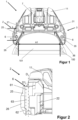
- the Figure 1 shows a view from below of an adult ski boot 100 held in a toe piece 1 of a ski binding.
- the toe piece 1 has a housing 11, a first sole holder 2 and a second sole holder 3.
- the first sole holder 2 and the second sole holder 3 are clamped towards each other by a clamping device 7 in order to clamp the ski boot 100 and to hold its front end.
- the tensioning device 7 is designed in the form of a spring.
- the first sole holder 2 is connected to the housing 11 via a first pivot joint 21.
- a pivot axis of the first pivot joint 21 runs essentially orthogonal to a surface of a ski (not shown) to which the toe piece 1 can be connected.
- the second sole holder 3 is connected to the housing 11 via a second pivot joint 31.
- a pivot axis of the second pivot joint 31 runs essentially parallel to the pivot axis of the first pivot joint 21.
- the first sole holder 2 comprises a first inner side wall 22 ( Figure 2 ), which rests against an outer side of the ski boot sole 101 of the ski boot 100 when the ski boot 100 is held in the toe piece 1.
- the second sole holder 3 comprises a second inner side wall 32 ( Figure 4 ), which rests against an outer side of the ski boot sole 101 of the ski boot 100 when the ski boot 100 is held in the toe piece 1.
- the first inner side wall 22 and the second inner side wall 32 face each other with a first clear horizontal distance A1, wherein the horizontal distance A1 preferably corresponds to a dimension of an international standard for adult ski boots (e.g. DIN ISO 5355 of May 2020: 69 ⁇ 2 mm).
- the first inner side wall 22 and the second inner side wall 32 can be moved by means of an adjusting device 6 from a first position which Figure 1 shows, into a second position (see Figure 3 ) can be adjusted.
- the toe piece 1 has a first configuration in which the sole holder 1 can accommodate an adult ski boot 100.
- the Figure 2 shows a detailed view of the first sole holder 2, exactly a section along AA from Figure 1 by the first sole holder 2 in the area of the adjustment device 6.
- the sole holder 2 of the embodiment shown comprises a sole holder housing 25 and a sole holding element 26 with the first inner side wall 22.
- the sole holding element 26 engages with a guide section 27 ( Figure 10 ) into an opening 29 ( Figure 9 ) of the sole holder housing 25.
- the guide section 27 is connected to the first inner side wall 22 or formed together with the first inner side wall 22. This means that when the guide section 27 is moved, the first inner side wall 22 moves at the same speed in the same direction.
- the sole holding element 26 is guided by the guide section 27 such that it executes a linear movement and/or a rotational movement with respect to the sole holder housing 25 when changing between the two positions.
- the adjustment device 6 is a shaft body with a shaft head 61 and a shaft base 62, which are mounted in the sole holder housing 25 so as to be rotatable about a common axis of rotation D.
- the shaft head 61 has an engagement for a tool, and the shaft base 62 is secured in the sole holder housing 25 with a rivet in the exemplary embodiment.
- the adjusting device 6 forms an eccentric section 63 with a rotation axis D1 that is horizontally offset from the common rotation axis D of the shaft head 61 and the shaft base 62.
- the rotation axes D and D1 run parallel to each other.
- the Figure 3 shows the sole holder 1 of the Figure 1 with a child's ski boot 200 held in it.
- the first inner side wall 22 and the second inner side wall 32 now have a distance A2 to each other, which is smaller than the distance A1.
- the second horizontal distance A2 corresponds to a dimension for the children's ski boot 200, in particular the dimension of an international standard for type C ski boots (e.g. DIN ISO 5355 of May 2020: 62 ⁇ 2 mm).
- Figure 3 the first inner side wall 22 lies against one side of a ski boot sole 201 of the children's ski boot 200, the second inner side wall 32 lies against an opposite side of the ski boot sole 201 of the children's ski boot 200 in order to connect the children's ski boot 200 to a ski (not shown) during alpine skiing and/or touring.
- Figure 1 and Figure 4 differ only in that the sole holding element 26 with the first inner side wall 22 relative to the sole holder housing 25 and the sole holding element 36 with the second inner side wall 32 relative to the sole holder housing 35 were moved by means of the respective adjusting device 6 from the first position, in which the mutually facing inner side walls 22, 32 have the clear horizontal distance A1 from one another, into a second position in which the mutually facing inner side walls 22, 32 have the clear distance A2 from one another.
- the sole retaining element 26 and the sole retaining element 36 have reinforcing ribs 40 on an upper side facing away from a ski surface (not shown), which reinforce, in particular, a wall section 28, 38 projecting orthogonally inward from the first and second inner side walls 22, 32, respectively.
- the reinforcing ribs 40 can additionally form guide elements that are guided, for example, in groove-shaped guides 23, 33 in the sole retaining housing 26, 36.
- the shaft head 61 comprises an indicator in the form of an arrow, the tip of which is in the Figure 4 points to a mark enclosed by the sole holder housing 25.
- the mark is a "GC” stands for “Child,” which, in the 180° position, indicates that the sole holder 1 is configured to accommodate only children's ski boots 200.
- Opposite the "C” mark is a second mark, "A,” which stands for “Adult.” With the arrowhead pointing toward the "A" in the 0° position, it indicates to the user that the sole holder 1, in this configuration, can only securely connect adult ski boots 100 to a ski.
- the shaft head 61 of the adjusting device 6 comprises a nose 64 which, together with locking counter-elements 24 ( Figure 9 ) can fix the adjustment device 6 at least in one end position.
- the adjustment device 6 is locked in the second position, so that the first inner side wall 22 and the second inner side wall 32 are not moved from the second position to the first position during alpine travel or during an ascent when high lateral forces occur.
- the Figure 5 is a view from below of the toe holder 1 of the Figure 4 .
- the Figure 4 shows more clearly the wall section 28 of the first inner side wall 22 and the wall section 38 of the second inner side wall 32.
- the wall sections 28, 38 rest on a free surface of the ski boot sole 101, 201 facing away from the ski surface when the ski boot 100, 200 is held in the toe piece 1 in order to secure the ski boot 100, 200 in the toe piece 1.
- the Figure 6 shows two sectional views of the sole holder 2.
- the Figure 6.1 shows a horizontal section through the sole holder 2 with an opening 20 ( Figure 9 ), which forms part of the pivot joint 21 in which the sole holder 2 is connected to the housing 11, the sole holder housing 25, the sole holding element 26 with the first inner side wall 22, and the adjusting device 6.
- the sole holding element 26 has an elongated hole 50 in the guide section 27, which extends substantially parallel to a central longitudinal axis L of the toe piece 1.
- the elongated hole 50 is a through-hole in which only the eccentric section 63 of the adjusting device 6 is mounted.
- a width transverse to the length of the elongated hole 50 essentially corresponds to the diameter of the adjusting device 6 in the region of the eccentric section 63.
- the Figure 6.2 shows a vertical section through the sole holder 2 with the sole holding element 26 in the second position.
- the adjusting device 6 is rotatably mounted with the shaft head 61 and the shaft base 62 in a substantially vertical through-opening 60, which is directed transversely to the substantially horizontal opening 29 that accommodates the guide section 27.
- the through-opening 60 has two round regions of different diameters, wherein the two regions have a common axis of rotation D, which is horizontally offset from the axis of rotation D1 of the eccentric section 63 and runs parallel to the axis of rotation D1.
- the eccentric section 63 rests with its lower end facing a ski surface, which protrudes radially beyond the shaft base 62, on a stop surface 70 formed by the sole holder housing 25.
- the sole holding element 26 forms a stop 71 for the end 66 of the shaft base 62 facing away from the ski surface.
- the adjusting device 6 can be inserted from above into the sole holder 2 through the elongated hole 50 into the opening 60 when the arrow in the shaft head 61 is in the 90° or 270° position.
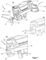
- the Figure 7 shows in three images a first alternative adjustment device 9 for connecting a sole holding element 26* with a sole holding housing 25* in the first position and in the second position.
- the toe piece 1 of the Figure 7 Except for the adjustment device corresponds to the front jaw 1 of the Figure 1 .
- FIG 7.1 is an exploded view showing the individual parts of the adjusting device 9.
- the adjusting device 9 consists of a screw body 99, which is provided with at least one threaded section 92, 93 ( Figure 7.3 ) in the sole holding body 25*, in particular into at least one counter-thread formed in the sole holding body 25*.
- the screw body 99 extends through a substantially vertically extending through-opening 91 in the sole holding element 26*.
- a diameter of the through-opening 91 substantially corresponds to the diameter in a lower free end 96 of the screw body 99, i.e., the end facing away from the screw head 95.
- the sole holding element 25* of the exemplary embodiment comprises two adjacent, spaced-apart through-openings 91.
- the thread 92, 93 can either be arranged adjacent to or near the screw head 95, or the thread 92, 93 is arranged near or at the free end 96 of the screw body 9.
- the screw head can also have the two threads 92, 93.
- the counter thread(s) 97, 98 ( Figure 7.2 ) are arranged or formed accordingly in the sole holder housing 25*.
- the Figure 7.2 shows the toe piece 1 in the configuration for adult ski boots 100 with the sole holding element 26* in the first position in which the two facing inner side walls 22, 32 have a clear horizontal distance A1 from each other.
- the Figure 7.3 shows the toe piece 1 in the configuration for children's ski boots 200 with the sole holding element 26* in the second position, in which both facing inner side walls 22, 32 have a clear horizontal distance A2 to each other.
- the Figure 8 shows in three pictures a further alternative adjustment device 8 for connecting a sole holding element 26** with a sole holding housing 25** in the first position and in the second position.
- the toe piece 1 of the Figure 8 Except for the adjustment device corresponds to the front jaw 1 of the Figure 1 .
- the Figure 8.1 shows the toe piece 1 and the sole holder 2 in their individual parts.
- the sole holder 2 comprises a sole holder housing 25**, a sole holding element 26**, a screw element 82, and a nut 85 into which the screw element 82 can be screwed with a threaded portion 88.
- the sole holder housing 25** has a one-sided, substantially horizontally extending opening 83 into which the sole holding element 26** or a guide portion 27 of the sole holding element 26** can be inserted.
- the side opposite the open side of the opening 83 has a bore 87 with a diameter that substantially corresponds to the diameter of the threaded portion 88 of the screw element 82.
- the sole holding element 26** comprises the inner side wall 22, the guide section 27, and a receptacle 86 formed in the guide section 27, in which the nut 82 can be arranged in a rotationally fixed and axially immovable manner.
- the screw element 82 is screwed with its threaded section 88 into the nut 85.
- the screw element 82 By turning the screw element 82, the nut 85 and thus the sole holding element 26** are moved into or out of the sole holding housing 26**.
- the Figure 8.2 shows the toe piece 1 in the configuration for adult ski boots 100 with the sole holding element 26** in the first position, in which the two inner side walls 22, 32 facing each other have a clear horizontal distance A1 from each other.
- the Figure 8.3 shows the toe piece 1 in the configuration for children's ski boots 200 with the sole holding element 26** in the second position, in which the two inner side walls 22, 32 facing each other have a clear horizontal distance A2 from each other.
- the Figure 9 shows in two pictures only the sole holder housing 25 of the sole holder 2 of the Figures 1 to 6
- the sole holder housing 25 is preferably molded in one piece, for example from a light metal such as aluminum, an aluminum alloy, or magnesium, or a plastic with or without reinforcement. Suitable processes include die casting, rapid prototyping, or machining with cutting tools.
- the sole holder housing 25 has a partially skeleton-like structure, with struts that can optimally absorb pre-calculated forces in strength and direction.
- the sole holder housing 25 comprises a first vertically extending through-opening 20 for an axis that pivotally connects the sole holder housing 25 to the housing 11 of the toe piece 1 in the pivot joint 21.
- a second vertically extending through-opening 60 rotatably supports the shaft head 61 and the shaft base 62 of the adjusting device 6.
- the Figure 9.2 shows that the sole holder housing 25 has a first horizontally extending through-opening 12, which receives one end of the clamping device 7.
- a second horizontally extending through-opening 29 is formed in the sole holder housing 25, which receives the guide section 27 of the sole holding element 26.
- the guides 23 for the reinforcing ribs 40 on the sole holding element 26 can also be seen.
- the Figure 10 shows, in two images, only the sole holding element 26, which can be inserted into the through-opening 29 of the sole holder housing 25, is guided in this through-opening 29, and can be moved into a first position and into a second position by the adjustment device 6.
- the sole holding element 26 comprises the guide section 27, the inner side wall 22 with the orthogonally inwardly projecting wall section 28.
- the wall section 28 has reinforcing ribs 40 on its upper side, which can be used as guides to guide the sole holding element 26 in the sole holder housing 25 during movement in the through-opening 29.
- the Figure 10.1 and the Figure 10 . 2 show the sole holding element 26 in two views, once from above ( Figure 10.1 ) and looking at the inner side wall 22 ( Figure 10.2 ).
- the sole holding element 26 has in the guide section 27 the elongated hole 50 which runs in the vertical direction and is aligned with the through opening 60 at least in one position of the sole holding element 26 in the through opening 29 of the sole holder housing 25, so that the adjusting device 6 can be positioned in the sole holder 2.
- the Figure 11 shows the adjustment device 6 of the front jaw 1 of the Figures 1 to 6 .
- the adjusting device 6 is a shaft body that can be rotated by means of a tool.
- the shaft body has a first end, which forms the shaft head 61, and a second end, which forms the shaft base 62.
- the shaft head 61 and the shaft base 63 have the common axis of rotation D.
- the shaft head 61 and/or the shaft base 62 can be rotatably mounted in a receptacle formed in the sole holder housing 25.
- An engagement for a tool is formed in the shaft head 61.
- a locking lug 64 is formed on the shaft head 61, which cooperates with a locking element 24, 34 formed on the sole holder housing 25 to secure the adjusting device 6 in at least one position, preferably an end position of the rotational movement, in order to fix the adjusting device 6 in this position by positive and/or non-positive engagement.
- the adjusting device comprises the eccentric section 63, which interacts with the shoe holding element 26 to adjust the distance A1 or distance A2 upon rotation of the adjusting device 6 by substantially 180°.
- the toggle lever effect can also ensure that the adjusting device 6 is secured in the second position.
- the securing of the adjusting device 6, particularly in the second position, in which the mutually facing inner side walls 22, 32 have the distance A2 for children's ski boots 200, results from the fact that, in the configuration with the distance A1 for adult ski boots 100, the inner side walls 22, 32 are held by the front end of the ski boot sole 101 in the first end position, in which the rear sides of the mutually facing inner side walls rest against the sole holder housing 25. Additional securing of the adjusting device 6 in the first position is therefore unnecessary.
- the adjusting device 6 can be made of metal, for example, steel, zinc, or a light metal alloy such as aluminum or an aluminum alloy. Magnesium or a plastic with or without reinforcement are also possible.
- the adjusting device 6 is preferably formed in one piece.
- the adjusting device 6 can, in particular, be machined from a solid body in an automatic lathe or manufactured using a rapid prototyping process. Other suitable processes include die-casting processes or machining with cutting tools.
- the Figure 12 shows a frame touring binding 300 with a frame 301, a front jaw 302 connected to the frame 301, and a rear jaw 303 connected to the frame 301.
- the frame 301 is connected at a front end in the direction of skiing in a pivot joint 305 to a base 306 or directly to a ski.
- the frame binding 300 shown comprises a locking lever 310, which can be moved from a first position, which is Figure 12 shown, can be moved into a second position. In the first position, the locking lever 310 connects the frame 301 to the ski so that the frame 301 cannot move substantially relative to the ski. In the second position, the locking lever 310 releases the frame 301 so that the rear end of the frame 301 can lift off the ski and the front end can be pivoted in the pivot joint 305, for example, for ascent with the ski.
- the front jaw 302 has a height-adjustable contact plate 311 for the front end of a ski boot sole underside.
- the Figure 12 A frame binding 300 is shown, does not mean that the Figures 1 to 11
- the toe piece 1 described is only suitable for this type of binding.
- the toe piece and the heel piece can also be connected to the ski directly or via a base, whereby it is advantageous for changing from the adult ski boot 100 to the children's ski boot 200 if the heel piece is attached to the base or to the ski in such a way that it can be adjusted relative to the toe piece in and against the direction of skiing.
Landscapes
- Footwear And Its Accessory, Manufacturing Method And Apparatuses (AREA)
Description
- Die Erfindung betrifft einen Vorderbacken einer Skibindung mit einem Gehäuse, einem ersten Sohlenhalter, der in einem ersten Drehgelenk mit dem Gehäuse verbunden ist, einem zweiten Sohlenhalter, der in einem zweiten Drehgelenk mit dem Gehäuse verbunden ist, und einer Spanneinrichtung, die den ersten Sohlenhalter und den zweiten Sohlenhalter aufeinander zu spannt. Der erste Sohlenhalter weist eine innere erste Seitenwand und der zweite Sohlenhalter eine innere zweite Seitenwand auf. Die erste innere Seitenwand und die zweite innere Seitenwand sind einander mit einem lichten horizontalen Abstand zugewandt. Der Vorderbacken umfasst ferner eine Verstelleinrichtung zur Verstellung eines horizontalen Abstands der einander zugewandten inneren Seitenwände.
- Da der Trend zu Leihskiern anhält, ist es im Sinn der Verleiher, dass Skibindungen zur Verfügung gestellt werden, die für verschiedene Typen von Skischuhen geeignet sind. Auch bei Nutzern, die sowohl im Gelände unterwegs sind als auch die Abfahrt lieben, sogenannte Freerider, sind Skibindungen, die mit unterschiedlichen Arten von Skischuhen kompatibel sind, nachgefragt. Zu den gängigen Arten von Skischuhen gehören die sogenannten "Skischuhe für den Pisten-Skilauf" nach DIN ISO 5355, deren Spezifikationen sowohl für Erwachsenenskischuhe (Typ A) wie auch Kinderskischuhe (Typ C) geregelt sind. Weiterhin regelt DIN ISO 9523 "Tourenskischuhe für Erwachsene". Mit der neu hinzu gekommenen Norm DIN ISO 23223 werden "Alpinskischuhe mit verbesserten Laufsohlen (im Handel als "GripWalk"-Sohlen bekannt) vorgegeben. Auch in DIN ISO 23223 wird zwischen Erwachsenen- (Typ A) und Kinderskischuhen (Typ C) unterschieden. Damit die Hersteller von Skibindungen eine möglichst große Kompatibilität ihrer Skibindungen mit den genormten Skischuhtypen sicherstellen können, sind unterschiedliche Verstellsysteme bekannt. Das heißt, dass zum Beispiel der Vorderbacken einer Skibindung so konstruiert wird, dass er durch Verstellung der Höhe einer Aufstandsfläche für eine Unterseite der Skischuhsohle oder durch eine Verstellung der Höhe des Vorderbackens selbst wahlweise einen Skischuh nach DIN ISO 9523 für das Tourengehen oder einen Skischuh nach DIN ISO 5355 für die Abfahrt aufnehmen kann. Die meisten Vorderbacken stellen in der Position der Aufstandsplatte für Skischuhe nach DIN ISO 5355 durch eine spezielle Formgebung der Aufstandsplatte auch eine Kompatibilität mit Skischuhen nach DIN ISO 23223 her.
- Der Fachmann ist daher stets auf der Suche nach Lösungen, um eine Bindung an möglichst mehrere unterschiedliche Typen von Skischuhen anzupassen, um den Leihmarkt und den Markt für den weniger spezialisierten Nutzer bedienen zu können. Im Stand der Technik gibt es zahlreiche Beispiele von Vorderbacken von Skibindungen, die höhenverstellbare Aufstandsplatte für das vordere Ende einer Skischuhsohlenunterseite vorschlagen, um mit unterschiedlich dicken Skischuhsohlen in ein und derselben Bindung nutzen zu können. Solch ein Vorderbacken ist beispielweise aus der
AT 517430 A1 - Die
DE 10 2012 217 867 B3 betrifft einen Vorderbacken einer Skibindung, bei der eine Haltevorrichtung für das vordere Ende einer Skischuhsole in einer Grundplatte in zwei Positionen verrastet werden kann, in einer ersten Position für einen Skischuh mit Alpinsohle und in einer zweiten Position für einen Skischuh mit Tourensohle. - Aus der
US 3 194 574 A ist ein einstellbarer Vorderbacken einer Sicherheitsbindung für einen Ski bekannt, bei dem mittels Stellschrauben ein Abstand der freien Enden der Sohlenhalter justiert werden kann. DieAT 515 264 B1 US 4 155 569 A bekannt. - Es ist die Aufgabe der Erfindung einen Vorderbacken für eine Skibindung bereit zu stellen, der einfach verstellt werden kann, um Skischuhe mit unterschiedlichen Skischuhsohlen aufzunehmen. Die Erfindung betrifft weiterhin eine Skibindung mit einem derartigen Vorderbacken. Die Aufgabe wird durch Anspruch 1 gelöst.
- Ein Aspekt der Erfindung betrifft einen Vorderbacken für eine Skibindung, wie eine Alpinbindung, eine Tourenbindung oder eine Freerider-Bindung. Der Vorderbacken kann dabei direkt oder über eine Basis mit dem Ski verbunden sein, oder zusammen mit einem Hinterbacken auf einer Platte, respektive einem Rahmen angeordnet sein. Der Vorderbacken umfasst ein Gehäuse, einen ersten Sohlenhalter, der in einem ersten Drehgelenk mit dem Gehäuse verbunden ist, einen zweiten Sohlenhalter, der in einem zweiten Drehgelenk mit dem Gehäuse verbunden ist, und eine Spanneinrichtung, die den ersten Sohlenhalter und den zweiten Sohlenhalter aufeinander zu spannt.
- Der erste Sohlenhalter weist eine innere erste Seitenwand und der zweite Sohlenhalter eine innere zweite Seitenwand auf. Die erste innere Seitenwand und die zweite innere Seitenwand sind einander mit einem lichten horizontalen Abstand zugewandt.
- Der Vorderbacken umfasst ferner eine Verstelleinrichtung zur Verstellung eines horizontalen Abstands der einander zugewandten inneren Seitenwände.
- Der erste Sohlenhalter des Vorderbackens kann ein Sohlenhaltergehäuse und ein Sohlenhalteelement mit der ersten inneren Seitenwand umfassen. Der zweite Sohlenhalter des Vorderbackens kann ein Sohlenhaltergehäuse und ein Sohlenhalteelement mit der zweiten inneren Seitenwand umfassen.
- Das Sohlenhalteelement des ersten bzw. des zweiten Sohlenhalters kann in dem Sohlenhaltergehäuse des jeweiligen Sohlenhalters gelagert sein. Bevorzug kann das Sohlenhalteelement in dem Sohlenhaltergehäuse bzw. relativ zu dem Sohlenhaltergehäuse aus einer ersten Position, in der die einander zugewandten inneren Seitenwände, respektive einander zugewandte äußere Oberseiten oder Oberflächen der inneren Seitenwände einen ersten lichten horizontalen Abstand haben, in eine zweite Position bewegt werden, in der die einander zugewandten inneren Seitenwände, respektive die einander zugewandten äußeren Oberseiten oder Oberflächen der inneren Seitenwände einen zweiten lichten horizontalen Abstand haben. Als Abstand wird der Abstand zwischen jeweils einem Punkt der ersten inneren Seitenwand und einem bezüglich einer Mittellängsachse des Vorderbackens gespiegelten Punkt der zweiten inneren Seitenwand angesehen. Dabei kann der Abstand zwischen verschiedenen durch die Spieglung definierten Punktpaaren unterschiedlich groß sein. Das Sohlenhalteelement ist dabei so im Sohlenhaltergehäuse gelagert, dass bei einer Verstellung des horizontalen Abstands der Seitenwände das Sohlenhalteelement bezüglich des Sohlenhaltergehäuses eine Linear- und/oder Rotationsbewegung ausführt.
- Die erste innere Seitenwand und die zweite innere Seitenwand weisen bevorzugt eine konturierte Oberfläche auf. Die erste innere Seitenwand und die zweite innere Seitenwand können bereichsweise gewölbt sein, Einbuchtungen beispielsweise am Rand oder an einem Eck umfassen oder in anderer Art geformt sein.
- Die erste innere Seitenwand und die zweite innere Seitenwand sind bevorzugt spiegelidentisch bezüglich einer Spiegelebene mit einer Spiegelachse, die mit der Mittellängsachse des Vorderbackens zusammenfällt.
- Die Verstelleinrichtung kann einen Verrastmechanismus umfassen, der den ersten Sohlenhalter oder die erste innere Seitenwand und den zweiten Sohlenhalter oder die zweite innere Sohlenwand in einer ersten Rastposition beim ersten Abstand und/oder wenigstens in einer zweiten Rastposition beim zweiten Abstand festlegt.
- Die Verstelleinrichtung kann zum Beispiel wenigstens ein Gewinde, ein Gewindeelement, wie eine Mutter, oder eine Durchgangsbohrung umfassen, das/die in dem Sohlenhaltergehäuse und/oder dem Sohlenhalteelement gebildet oder angeordnet ist, und in welches ein Schraubenkörper eingeschraubt oder ein Splint eingesteckt werden kann, um den lichten horizontalen Abstand zwischen dem ersten Sohlenhalter oder der ersten inneren Seitenwand und der zweiten Sohlenhalter oder der zweiten inneren Seitenwand einzustellen und/oder festzulegen.
- Die Verstelleinrichtung kann eine Welle sein, mit einem Wellenkopf, der ein erstes oder oberes, einer Skioberfläche abgewandtes Ende der Welle bildet, und einem Wellenfuß, der ein zweites oder unteres, der Skioberfläche zugewandtes Ende der Welle bildet, und einem Exzenterabschnitt, der zwischen dem Wellenkopf und dem Wellenfuß angeordnet ist.
- Der Wellenkopf und der Wellenfuß können im ersten und zweiten Sohlenhalter bzw. dem entsprechenden Sohlenhaltergehäuse drehbar gelagert sein. Der Exzenterabschnitt ist in einer Durchgangsöffnung, die im Sohlenhalteelement gebildet ist und im Sohlenhalterelement im Wesentlichen vertikal, das heißt, orthogonal zur Skioberfläche gebildet ist, angeordnet.
- Die als Welle ausgebildete Verstelleinrichtung kann aus einer Ruheposition, in der das Sohlenhalteelement in der ersten Position oder 0° Position ist, um im Wesentliche 180°, bevorzugt um mehr als 180° verstellt oder verdreht werden, um das Sohlenhalteelement in die zweite Position oder 180° Position zu bewegen. Die Verstelleinrichtung kann als Kniehebel oder kniehebelartig wirken, so dass bei einer Verstellbewegung der Verstelleinrichtung bzw. Drehung der Welle um die Wellenachse um mehr als 180° durch Überstreckung ein Verriegelungseffekt der Verstelleinrichtung in der zweiten Position erreicht wird.
- Um die Verstelleinrichtung zu sichern oder in der Überstreckung zusätzlich zu sichern, kann eine Sicherung der Welle, insbesondere durch Kraft- und/oder Formschluss, wenigstens in der zweiten Position vorgesehen sein. Zur Sicherung kann beispielsweise der Wellenkopf ein Rastelement wie eine Rastnase oder Rastkerbe umfassen, die mit einem Gegenrastelement, das in oder an dem Sohlenhaltergehäuse gebildet ist, verrastet, wenn die Verstelleinrichtung oder Welle in der zweiten Position ist.
- Erfindungsgemäß kann mittels der Verstelleinrichtung der lichte horizontale Abstand der einander zugewandten inneren Seitenwände von einem ersten lichten horizontalen Abstand von 69±2 mm auf einen zweiten lichten horizontalen Abstand von 62±2 mm verändert werden. Dabei entspricht der erste Abstand von 69±2 mm dem Wert der DIN ISO 5355 vom Mai 2020 bzw. der DIN ISO 23223 vom Juli 2020 für die Breite des vorderen Endes einer Skischuhsohle für einen Erwachsenenskischuh (Typ A). In dieser Konfiguration kann auch ein Tourenskischuh nach DIN ISO 9523 aufgenommen werden. Der zweite Abstand von 62±2 mm entspricht dem Wert der DIN ISO 5355 vom Mai 2020 bzw. der DIN ISO 23223 vom Juli 2020 für die Breite eines vorderen Endes einer Skischuhsohle für Kinderskischuhe (Typ C).
- Das heißt, das der vorbeschriebene Vorderbacken flexibel einsetzbar ist. Die Skibindung kann sozusagen mit dem Nutzer vom Kinderskischuh zum Erwachsenenskischuh "mitwachsen". Das ist nicht nur im privaten Bereich besonders vorteilhaft, sondern auch bei Leihskiern, da ein Ski mit einem derart verstellbaren Vorderbacken in einer ersten Konfiguration an Kinder und in einer zweiten Konfiguration an Erwachsene verliehen werden kann, wobei die Einstellung schnell, sicher und einfach durch Servicepersonal vor den Augen des Kunden vorgenommen werden kann.
- Skischuhe für Erwachsene und Kinder weisen gemäß der genannten Norm nicht nur unterschiedliche Breiten des vorderen Endes der Skischuhsohle auf, sondern auch unterschiedliche Abstände der Oberseite des vorderen Skischuhsohlenendes zur Aufstandsfläche des Skischuhs im Vorderbacken. Die DIN ISO 5333 und DIN ISO 23223 (Typ A) für Erwachsene gibt einen vertikalen Abstand zwischen Oberseite des vorderen Endes der Skischuhsohle zur Aufstandsfläche für den Skischuh von 19±1 mm vor, für Kinderschuhe (DIN ISO 5355 und DIN ISO 23223 Typ C) von 16,5±1,5 mm. Für Tourenskischuhe nach DIN ISO 9523 ist ein größerer, von den zuvor genannten Maßen abweichender, vertikaler Abstand notwendig, der aber durch die Norm nicht vorgegeben ist.
- Der Vorderbacken kann daher ferner eine Aufstandsfläche für das vordere Ende einer im Vorderbacken gehaltenen Skischuhsohlenunterseite umfassen. Die Aufstandsfläche kann in Vertikalrichtung verstellbar bzw. höhenverstellbar sein. Bei der Aufstandsfläche kann es sich beispielsweise um eine Aufstandsplatte handeln, die relativ zu dem Vorderbackengehäuse in und gegen die Skilaufrichtung auf einer Rampe verschoben werden kann. Durch das Verschieben der Aufstandsplatte wird ein Abstand der von der Skioberseite abgewandten Oberseite der Aufstandsplatte in Vertikalrichtung verändert, das heißt, vergrößert oder verkleinert. Bevorzugt kann die Aufstandsplatte eine erste Position für Skischuhe nach DIN ISO 5333 bzw. DIN ISO 23223 Typ A einnehmen , in der der vertikale Abstand zwischen einer auf der Aufstandsplatte aufstehenden Unterseite der Skischuhsohle und einer freien Oberseite des vorderen Endes der Skischuhsole 19±1 mm ist, und eine zweite Position einnehmen, für Skischuhe nach DIN ISO 5333 bzw. DIN ISO 23223 Typ C, in der der vertikale Abstand zwischen einer auf der Aufstandsplatte aufstehenden Unterseite der Skischuhsohle und einer freien Oberseite des vorderen Endes der Skischuhsole 16,5±1,5 mm ist. Weiterhin kann die Aufstandsplatte eine dritte Position für Skischuhe nach DIN ISO 9523 einnehmen, wobei die Position von den beiden zuvor genannten abweicht.
- Das Sohlenhalteelement kann ein Formkörper sein, der aus einem Kunststoff oder einem Leichtmetall, wie Aluminium, gebildet ist. Der Formkörper kann spanabhebend aus einem Materialblock herausgearbeitet sein oder in zum Beispiel einem Spritzgussverfahren oder einem Sinterverfahren oder durch ein anderes Rapid Prototyping Verfahren, wie beispielsweis 3D-Druck, hergestellt sein.
- Das Sohlenhalteelement kann einen Führungsabschnitt, die innere Seitenwand, die mit dem Führungsabschnitt verbunden ist, und einen vom vertikalen oberen, von der Skioberseite entfernten Ende der inneren Seitenwand im Wesentlichen orthogonal nach innen vorstehenden Wandabschnitt umfassen. Der Führungsabschnitt greift beispielsweise in das Sohlenhaltergehäuse ein, und wird im Eingriff mit dem Sohlenhaltergehäuse geführt. Bei einem in dem Vorderbacken gehaltenen Skischuh liegt die innere Seitenwand seitlich an einem vorderen Ende einer Sohle des Skischuhs an, und der orthogonal vorstehende Wandabschnitt überdeckt einen Bereich der freien Oberseite des vorderen Endes der Sohle des Skischuhs und/oder liegt auf der freien Oberseite auf.
- Ein zweiter Aspekt betrifft eine Skibindung mit einem vorbeschriebenen Vorderbacken und einem Hinterbacken, sowie optional einer Skibremse. Dabei können Vorder- und Hinterbacken direkt oder über eine Basis mit einem Ski verbunden werden oder Vorder- und Hinterbacken können mit einem Rahmen oder einer Platte verbunden sein, der/die mit einem Ski verbunden werden kann.
- Ein weiterer Aspekt betrifft einen Ski mit einer Skibindung nach dem zweiten Aspekt. Umfasst die Skibindung den Rahmen oder die Platte, kann diese an ihrem der Skispitze zugewandten vorderen Ende in einem Schwenkgelenk mit einer Schwenkachse, die im Wesentlichen quer zur Skilängsachse weist, mit einem Ski verbunden werden, so dass der Rahmen oder die Platte zum Beispiel in einem Tourenmodus beim Aufstieg in dieser Schwenkachse relativ zum Ski verschwenkt werden kann. Das hintere Ende des Rahmens oder der Platte kann lösbar mit dem Ski verriegelt sein, so dass der Rahmen/die Platte bei gelöster Verriegelung von der Skioberfläche abheben kann (Tourengehen, Aufstieg) und bei verriegelter Verriegelung mit der Skioberfläche fest verbunden ist (Abfahrt, Alpinfahrt).
- Der Einfachheit halber werden folgend Skischuhe nach DIN ISO 5355 Typ A, Skischuhe nach DIN ISO 23223 Typ A und Tourenskischuhe nach DIN ISO 9523 gesammelt als "Erwachsenenskischuhe" bezeichnet. Skischuhe nach DIN ISO 5355 Typ C und Skischuhe nach DIN ISO 23223 Typ C als "Kinderskischuhe".
- Es versteht sich von selbst, dass der Begriff "Kinderskischuh" bzw. "Erwachsenenskischuh" nicht nur auf Skischuhe der zuvor genannten einschlägigen Normen beschränkt ist, sondern auch Skischuhe umfasst, deren Spezifikationen mit denen der einschlägigen Normen vergleichbar sind. Diese Spezifikationen sind insbesondere die Breite des vorderen Endes einer Skischuhsohle und der vertikale Abstand zwischen Oberseite des vorderen Endes der Skischuhsohle zur Aufstandsfläche für den Skischuh.
- Ein weiterer Aspekt betrifft ein Verfahren zur Verstellung eines Vorderbackens mit einem ersten Sohlenhalter und einem zweiten Sohlenhalter aus einer ersten Konfiguration, in welcher der Vorderbacken einen Erwachsenenskischuh aufnehmen kann, in eine zweite Konfiguration, in welcher der Vorderbacken einen Kinderskischuh aufnehmen kann. Zum Einstellen der zweiten Konfiguration wird mit Hilfe eines Werkzeuges ein in einem ersten Sohlenhaltergehäuse beweglich gelagertes Sohlenhalteelement aus dem ersten Sohlenhaltergehäuse in Richtung einer Skimittellängsachse heraus bewegt und mit Hilfe des Werkzeuges ein in dem zweiten Sohlenhaltergehäuse beweglich gelagertes Sohlenhalteelement in Richtung der Skimittellängsachse heraus bewegt, und eine Aufstandsplatte für eine vordere Skischuhsohlenunterseite wird in der Höhe für die zweite Konfiguration eingestellt. Gleiches gilt -mutatis mutandis- zum Verstellen des Vorderbackens aus der zweiten Konfiguration in die erste Konfiguration.
- Im Folgenden wir ein Ausführungsbeispiel eines vorbeschriebenen Vorderbackens anhand von Figuren näher erläutert. Die Figuren zeigen im Einzelnen:
- Figur 1:
- Vorderbacken von unten mit Erwachsenenskischuh
- Figur 2:
- Schnitt A-A durch Sohlenhalter des Vorderbackens der
Figur 1 - Figur 3:
- Vorderbacken von unten mit Kinderskischuh
- Figur 4:
- perspektivische Ansicht des Vorderbackens der
Figur 3 - Figur 5:
- Vorderbacken der
Figur 3 von schräg unten - Figur 6:
- Horizontalschnitt und Vertikalschnitt durch Sohlenhalter des Vorderbackens der
Figur 3 - Figur 7:
- Vorderbacken mit erster alternativer Sicherung des Sohlenhalteelements im Sohlenhaltergehäuse in drei Skizzen
- Figur 8:
- Vorderbacken mit zweiter alternativer Sicherung des Sohlenhalteelements im Sohlenhaltergehäuse in drei Skizzen
- Figur 9:
- Sohlenhaltergehäuse in zwei Ansichten
- Figur 10:
- Sohlenhalteelement in zwei Ansichten
- Figur 11:
- Verstelleinrichtung in zwei Ansichten
- Figur 12:
- Skibindung mit Vorderbacken und Hinterbacken montiert auf einem Rahmen/ einer Platte
- Die
Figur 1 zeigt in einer Ansicht von unten einen Erwachsenenskischuh 100, der in einem Vorderbacken 1 einer Skibindung gehalten ist. Der Vorderbacken 1 weist ein Gehäuse 11, einen ersten Sohlenhalter 2 und einen zweiten Sohlenhalter 3 auf. Der erste Sohlenhalter 2 und der zweite Sohlenhalter 3 werden durch eine Spanneinrichtung 7 aufeinander zu gespannt, um den Skischuh 100 respektive dessen vorderes Ende zu halten. Die Spanneinrichtung 7 ist in Form einer Feder ausgebildet. - Der erste Sohlenhalter 2 ist in einem ersten Schwenkgelenk 21 mit dem Gehäuse 11 verbunden. Eine Schwenkachse des ersten Schwenkgelenks 21 verläuft im Wesentlichen orthogonal zu einer Oberfläche eines nicht dargestellten Skis mit dem der Vorderbacken 1 verbunden werden kann. Der zweite Sohlenhalter 3 ist in einem zweiten Schwenkgelenk 31 mit dem Gehäuse 11 verbunden. Eine Schwenkachse des zweiten Schwenkgelenks 31 verläuft im Wesentlichen parallel zur Schwenkachse des ersten Schwenkgelenks 21.
- Der erste Sohlenhalter 2 umfasst eine erste innere Seitenwand 22 (
Figur 2 ), die an einer Außenseite der Skischuhsohle 101 des Skischuhs 100 anliegt, wenn der Skischuh 100 in dem Vorderbacken 1 gehalten wird. Der zweite Sohlenhalter 3 umfasst eine zweite innere Seitenwand 32 (Figur 4 ), die an einer Außenseite der Skischuhsohle 101 des Skischuhs 100 anliegt, wenn der Skischuh 100 in dem Vorderbacken 1 gehalten ist. Die erste innere Seitenwand 22 und die zweite innere Seitenwand 32 sind einander mit einem ersten lichten horizontalen Abstand A1 zugewandt, wobei der horizontale Abstand A1 bevorzugt einem Maß einer internationalen Norm für Erwachsenenskischuhe entspricht (z.B. DIN ISO 5355 vom Mai 2020: 69±2 mm). - Die erste innere Seitenwand 22 und die zweite innere Seitenwand 32 können mittels einer Verstelleinrichtung 6 aus einer ersten Position, die die
Figur 1 zeigt, in eine zweite Position (sieheFigur 3 ) verstellt werden. - In der gezeigten Position weist der Vorderbacken 1 eine erste Konfiguration auf, in der der Sohlenhalter 1 einen Erwachsenenskischuh 100 aufnehmen kann.
- Die
Figur 2 zeigt eine Detailansicht des ersten Sohlenhalters 2, genau einen Schnitt entlang A-A ausFigur 1 durch den ersten Sohlenhalter 2 im Bereich der Verstelleinrichtung 6. Der Sohlenhalter 2 des gezeigten Ausführungsbeispiels umfasst ein Sohlenhaltergehäuse 25 und ein Sohlenhalteelement 26 mit der ersten inneren Seitenwand 22. - Gezeigt sind das Gehäuse 11 des Vorderbackens 1, das Sohlenhaltergehäuse 25, das Sohlenhalteelement 26 mit der ersten inneren Seitenwand 22 und die Verstelleinrichtung 6 in der ersten Position, in der eine Rückseite der ersten inneren Seitenwand 22 an dem Sohlenhaltergehäuse 25 anliegt
- Das Sohlenhalteelement 26 greift mit einem Führungsabschnitt 27 (
Figur 10 ) in eine Öffnung 29 (Figur 9 ) des Sohlenhaltergehäuses 25 ein. Der Führungsabschnitt 27 ist mit der ersten inneren Seitenwand 22 verbunden oder zusammen mit der ersten inneren Seitenwand 22 geformt. Das heißt, wird der Führungsabschnitt 27 bewegt, bewegt sich die erste innere Seitenwand 22 mit gleicher Geschwindigkeit in die gleiche Richtung. Das Sohlenhalteelement 26 ist durch den Führungsabschnitt 27 so geführt, dass es bezüglich des Sohlenhaltergehäuses 25 eine Linearbewegung und/oder eine Rotationsbewegung beim Wechsel zwischen den beiden Positionen ausführt. - Bei der Verstelleinrichtung 6 handelt es sich um einen Wellenkörper mit einem Wellenkopf 61 und einem Wellenfuß 62, die um eine gemeinsame Drehachse D drehbar in dem Sohlenhaltergehäuse 25 gelagert sind. Der Wellenkopf 61 weist einen Eingriff für ein Werkzeug auf, der Wellenfuß 62 ist im Ausführungsbeispiel mit einem Niet im Sohlenhaltergehäuse 25 gesichert.
- Zwischen dem Wellenkopf 61 und dem Wellenfuß 62 bildet die Verstelleinrichtung 6 einen Exzenterabschnitt 63 mit einer Drehachse D1, die zur gemeinsamen Drehachse D von Wellenkopf 61 und Wellenfuß 62 horizontal versetzt ist. Die Drehachsen D und D1 verlaufen parallel zueinander.
- Die
Figur 3 zeigt den Sohlenhalter 1 derFigur 1 mit einem darin gehaltenen Kinderskischuh 200. Zum Unterschied des Sohlenhalters 1 derFigur 1 weisen die erste innere Seitenwand 22 und die zweite innere Seitenwand 32 jetzt einen Abstand A2 zueinander auf, der kleiner ist als der Abstand A1. Bevorzugt entspricht der zweite horizontale Abstand A2 einem Maß für den Kinderskischuh 200, insbesondere dem Maß einer internationalen Norm für Skischuhe vom Typ C (z.B. DIN ISO 5355 vom Mai 2020: 62±2 mm). In derFigur 3 liegt die erste innere Seitenwand 22 an einer Seite einer Skischuhsole 201 des Kinderskischuhs 200 an, die zweite innere Seitenwand 32 liegt an einer gegenüberliegenden Seite des Skischuhsohle 201 des Kinderskischuhs 200 an, um den Kinderskischuh 200 bei einer Alpinfahrt und/oder beim Tourengehen mit einem nicht gezeigten Ski zu verbinden. - In der
Figur 4 ist der Sohlenhalter 1 in einer perspektivischen Sicht gezeigt, wobei die Bezugszeichen identisch mit den Bezugszeichen derFigur 1 und derFigur 2 sind. -
Figur 1 undFigur 4 unterscheiden sich nur dadurch, dass das Sohlenhalteelement 26 mit der ersten inneren Seitenwand 22 relativ zu dem Sohlenhaltergehäuse 25 und das Sohlenhaltelement 36 mit der zweiten inneren Seitenwand 32 relativ zu dem Sohlenhaltergehäuse 35 mittels der jeweiligen Verstelleinrichtung 6 aus der ersten Position, in der die einander zugewandten inneren Seitenwände 22, 32 den lichten horizontalen Abstand A1 zueinander haben, in eine zweite Position, in der die einander zugewandten inneren Seitenwände 22, 32 den lichten Abstand A2 zueinander haben, bewegt wurden. - Das Sohlenhalteelement 26 und das Sohlenhalteelement 36 weisen an einer von einer nicht dargestellten Skioberfläche abgewandten Oberseite Verstärkungsrippen 40 auf, die insbesondere einen von der ersten bzw. der zweiten inneren Seitenwand 22, 32 orthogonal nach innen vorstehenden Wandabschnitt 28, 38 verstärken. Die Verstärkungsrippen 40 können zusätzlich Führungselemente bilden, die in z.B. nutenförmigen Führungen 23, 33 im Sohlenhaltergehäuse 26, 36 geführt werden.
- Zum Einstellen der zweiten Position wurde die Verstelleinrichtung 9 mittels eines Werkzeuges um wenigstens 180° verdreht. Der Wellenkopf 61 umfasst eine Anzeige in Form eines Pfeiles, dessen Spitze in der
Figur 4 auf eine vom Sohlenhaltergehäuse 25 umfasste Marke zeigt. Bei der Marke handelt es sich um ein "GC" für "Child", die in der 180° Lage anzeigt, dass sich der Sohlenhalter 1 eine Konfiguration hat, in der er nur Kinderskischuhe 200 aufnehmen kann. Der Marke "C" gegenüber liegt eine zweite Marke "A", was für "Adult" steht, dem Nutzer also bei auf das "A" in der 0° Lage gerichteter Pfeilspitze anzeigt, dass der Sohlenhalter 1 in dieser Konfiguration nur Erwachsenenskischuhe 100 sicher mit einem Ski verbinden kann. - Der Wellenkopf 61 der Verstelleinrichtung 6 umfasst eine Nase 64 die zusammen mit an dem Sohlenhaltergehäuse 25, 35 gebildeten Rastgegenelementen 24 (
Figur 9 ) die Verstelleinrichtung 6 zumindest in einer Endposition festlegen kann. Bevorzugt wird die Verstelleinrichtung 6 in der zweiten Position verrastet, so dass die erste innerer Seitenwand 22 und die zweite innere Seitenwand 32 während einer Alpinfahrt oder während eines Aufstiegs beim Auftreten hoher Seitenkräfte nicht aus der zweiten Position in die erste Position bewegt werden. - Die
Figur 5 ist eine Ansicht von schräg unten auf den Zehenhalter 1 derFigur 4 . DieFigur 4 zeigt deutlicher den Wandabschnitt 28 der ersten inneren Seitenwand 22 und den Wandabschnitt 38 der zweiten inneren Seitenwand 32. Die Wandabschnitte 28, 38 liegen bei in dem Vorderbacken gehaltenem Skischuh 100, 200 auf einer von der Skioberfläche abgewandten freien Oberfläche der Skischuhsohle 101, 201 auf, um den Skischuh 100, 200 in dem Vorderbacken 1 zu sichern. - Die
Figur 6 zeigt zwei Schnittansichten des Sohlenhalters 2. - Die
Figur 6.1 zeigt einen Horizontalschnitt durch den Sohlenhalter 2 mit einer Öffnung 20 (Figur 9 ), die Teil des Schwenkgelenks 21 bildet, in dem der Sohlenhalter 2 mit dem Gehäuse 11 verbunden ist, dem Sohlenhaltergehäuse 25, dem Sohlenhalteelement 26 mit der ersten inneren Seitenwand 22, und der Verstelleinrichtung 6. - Das Sohlenhalteelement 26 hat im Führungsabschnitt 27 ein Langloch 50, das sich im Wesentlichen parallel zu einer Mittellängsachse L des Vorderbackens 1 erstreckt.
- Beim dem Langloch 50 handelt es sich um eine Durchgangsöffnung, in der nur der Exzenterabschnitt 63 der Verstelleinrichtung 6 gelagert ist. Eine Breite quer zur Länge des Langlochs 50 entspricht im Wesentlichen dem Durchmesser der Verstelleinrichtung 6 im Bereich des Exzenterabschnitts 63.
- Die
Figur 6.2 zeigt einen Vertikalschnitt durch den Sohlenhalter 2 mit dem Sohlenhalteelement 26 in der zweiten Position. Die Verstelleinrichtung 6 ist mit dem Wellenkopf 61 und dem Wellenfuß 62 in einer im Wesentlichen vertikalen Durchgangsöffnung 60, die quer zu der im Wesentlichen horizontalen Öffnung Öffnung 29, die den Führungsabschnitt 27 aufnimmt, gerichtet ist, drehbar gelagert. Im Ausführungsbeispiel weist die Durchgangsöffnung 60 zwei runde Bereiche unterschiedlicher Durchmesser auf, wobei die beiden Bereiche die gemeinsame Drehachse D haben, die horizontal zur Drehachse D1 des Exzenterabschnitts 63 versetzt ist und parallel zur Drehachse D1 verläuft. Der Exzenterabschnitt 63 liegt mit seinem einer Skioberfläche zugewandten unteren Ende, das über den Wellenfuß 62 radial vorsteht, auf einer Anschlagsfläche 70 auf, die von dem Sohlenhaltergehäuse 25 gebildet wird. Das Sohlenhalteelement 26 bildet einen Anschlag 71 für das von der Skioberfläche abgewandte Ende 66 des Wellenfußes 62. - In Zusammenschau der
Figuren 2 und6.1 bzw. 6.2 wird deutlich, dass durch das Drehen der Verstelleinrichtung 6 um im Wesentlichen 180° das Sohlenhalteelement 26 zwangsläufig aus der ersten Position (Figur 2 ) in die zweite Position (Figur 6.2 ) bewegt wird. In der ersten Position und in der zweiten Position ist die Verstelleinrichtung 6 durch das Zusammenwirken der Anschläge 70, 71 mit dem unteren Ende 65 des Exzenterabschnitts 63 und dem oberen Ende 66 des Wellenfußes 62 verliersicher im Sohlenhaltergehäuse 25 gesichert. Wenn der Durchmesser des Exzenterabschnitts 63 und des Wellenfußes 62 im Wesentlichen gleich sind, wie im gezeigten Ausführungsbeispiel, kann die Verstelleinrichtung 6 von oben in den Sohlenhalter 2 durch das Langloch 50 in die Öffnung 60 eingesetzt werden, wenn sich der Pfeil im Wellenkopf 61 in der 90° oder 270° Position befindet. - Die
Figur 7 zeigt in drei Bildern eine erste alternative Verstelleinrichtung 9, um ein Sohlenhalteelement 26* mit einem Sohlenhaltergehäuse 25* in der ersten Position und in der zweiten Position zu verbinden. Der Vorderbacken 1 derFigur 7 entspricht bis auf die Verstelleinrichtung dem Vorderbacken 1 derFigur 1 . -
Figur 7.1 ist eine Explosionszeichnung, die die Einzelteile der Verstelleinrichtung 9 zeigt. Die Verstelleinrichtung 9 besteht aus einem Schraubenkörper 99, der mit wenigstens einem Gewindeabschnitt 92, 93 (Figur 7.3 ) in dem Sohlenhaltekörper 25*, insbesondere in wenigstens ein im Sohlenhalterkörper 25* ausgebildetes Gegengewinde, eingeschraubt werden kann. Der Schraubenkörper 99 durchgreift dabei eine im Wesentlichen vertikal verlaufende Durchgangsöffnung 91 im Sohlenhalteelement 26*. Ein Durchmesser der Durchgangsöffnung 91 entspricht im Wesentlichen dem Durchmesser in einem unteren, das heißt, vom Schraubenkopf 95 abgewandten freien Ende 96 des Schraubenkörpers 99. Um das Sohlenhalteelement 25* in der ersten Position und in der zweiten Position zu sichern, umfasst das Sohlenhalteelement 25* des Ausführungsbeispiels zwei nebeneinander liegende, beabstandete Durchgangsöffnungen 91. - Das Gewinde 92, 93 kann entweder anschließend an oder nahe dem Schraubenkopf 95 angeordnet sein, oder das Gewinde 92, 93 ist nahe dem oder am feien Ende 96 des Schraubenkörpers 9 angeordnet. Grundsätzlich kann der Schraubenkopf auch die beiden Gewinde 92, 93 aufweisen. Das oder die Gegengewinde 97, 98 (
Figur 7.2 ) sind entsprechend im Sohlenhaltergehäuse 25* angeordnet oder ausgebildet. - Die
Figur 7.2 zeigt den Vorderbacken 1 in der Konfiguration für Erwachsenenskischuhe 100 mit dem Sohlenhalteelement 26* in der ersten Position, in der die beiden einander zugewandten inneren Seitenwände 22, 32 einen lichten horizontalen Abstand A1 zueinander haben. - Die
Figur 7.3 zeigt den Vorderbacken 1 in der Konfiguration für Kinderskischuhe 200 mit dem Sohlenhalteelement 26* in der zweiten Position, in der beiden einander zugewandten inneren Seitenwände 22, 32 einen lichten horizontalen Anstand A2 zueinander haben. - Die
Figur 8 zeigt in drei Bildern eine weitere alternative Verstelleinrichtung 8, um ein Sohlenhalteelement 26** mit einem Sohlenhaltergehäuse 25** in der ersten Position und in der zweiten Position zu verbinden. Der Vorderbacken 1 derFigur 8 entspricht bis auf die Verstelleinrichtung dem Vorderbacken 1 derFigur 1 . - Die
Figur 8.1 zeigt den Vorderbacken 1 und den Sohlenhalter 2 in seinen Einzelteilen. Der Sohlenhalter 2 umfass ein Sohlenhaltergehäuse 25**, ein Sohlenhalteelement 26**, ein Schraubenelement 82 und einer Mutter 85, in die das Schraubenelement 82 mit einem Gewindeabschnitt 88 eingeschraubt werden kann. - Das Sohlenhaltergehäuse 25** weist eine einseitig offene, im Wesentlichen horizontal verlaufende Öffnung 83 auf, in die das Sohlenhalteelement 26** respektive ein Führungsabschnitt 27 des Sohlenhalteelements 26** eingeführt werden kann. Die der offen Seite der Öffnung 83 gegenüberliegende Seite weist eine Bohrung 87 auf, mit einem Durchmesser, der im Wesentlichen dem Durchmesser des Gewindeabschnitts 88 des Schraubenelements 82 entspricht.
- Das Sohlenhalteelement 26** umfasst die innere Seitenwand 22, den Führungsabschnitt 27 und eine im Führungsabschnitt 27 gebildete Aufnahme 86, in der die Mutter 82 drehfest und axial nicht beweglich angeordnet werden kann. Zum Verstellen des Sohlenhalteelements 26** von der ersten Position in die zweite Position wird das Schraubenelement 82 mit seinem Gewindeabschnitt 88 in die Mutter 85 eingeschraubt. Durch Drehen des Schraubenelements 82 wird die Mutter 85 und damit das Sohlenhalteelement 26** in des Sohlenhaltergehäuse 25** hinein oder aus den Sohlenhaltergehäuse 26** herausbewegt.
- Die
Figur 8.2 zeigt den Vorderbacken 1 in der Konfiguration für Erwachsenenskischuhe 100 mit dem Sohlenhalteelement 26** in der ersten Position, in der die beiden einander zugewandten inneren Seitenwände 22, 32 einen lichten horizontalen Abstand A1 zueinander haben. - Die
Figur 8.3 zeigt den Vorderbacken 1 in der Konfiguration für Kinderskischuhe 200 mit dem Sohlenhalteelement 26** in der zweiten Position, in der beiden einander zugewandten inneren Seitenwände 22, 32 einen lichten horizontalen Anstand A2 zueinander haben. - Zu den vorhergehenden Figuren sei angemerkt, dass alle Merkmale, die nur für einen der Sohlenhalter 2, 3 beschrieben wurden, ebenso für den nicht gezeigten Sohlenhalter 2, 3 gelten. Dies gilt insbesondere für die Merkmale der entsprechenden Sohlenhaltergehäuse 25, 35; 25*, 35*; 25**, 35** und die Merkmale der entsprechenden Sohlenhalteelemente 26, 36; 26*, 36*; 26**, 36**.
- Die
Figur 9 zeigt in zwei Bildern allein das Sohlenhaltergehäuse 25 des Sohlenhalters 2 derFiguren 1 bis 6 . Das Sohlenhaltergehäuse 25 ist bevorzugt in einem Stück geformt, beispielsweise aus Leichtmetall, wie Aluminium, einer Aluminiumlegierung oder Magnesium, oder einem Kunststoff mit oder ohne Verstärkung. Geeignete Verfahren sind u.a. Formgussverfahren, Rapid-Prototyping oder Bearbeitung mit spanabhebenden Werkzeugen. - Das Sohlenhaltergehäuse 25 weist teilweise einen skelettähnlichen Aufbau auf, mit Streben, die vorausberechnete Kräfte in Stärke und Richtung optimal aufnehmen können.
- Wie
Figur 9.1 zeigt, umfasst das Sohlenhaltergehäuse 25 eine erste vertikal verlaufende Durchgangsöffnung 20 für eine Achse, die das Sohlenhaltergehäuse 25 in dem Schwenkgelenk 21 schwenkbar mit dem Gehäuse 11 des Vorderbackens 1 verbindet. Eine zweite vertikal verlaufende Durchgangsöffnung 60, lagert den Wellenkopf 61 und den Wellenfuß 62 der Verstelleinrichtung 6 drehbar. - Die
Figur 9.2 zeigt, dass das Sohlenhaltergehäuse 25 eine erste horizontal verlaufende Durchgangsöffnung 12 aufweist, die ein Ende der Spanneinrichtung 7 aufnimmt. Eine zweite horizontal verlaufende Durchgangsöffnung 29 ist im Sohlenhaltergehäuse 25 gebildet, die den Führungsabschnitt 27 des Sohlenhalteelements 26 aufnimmt. Es sind weiterhin die Führungen 23 für die Verstärkungsrippen 40 am Sohlenhalteelement 26 zu sehen. - Die
Figur 10 zeigt in zwei Bildern allein das Sohlenhalteelement 26, das in die Durchgangsöffnung 29 des Sohlenhaltergehäuses 25 einschoben werden kann, in dieser Durchgangsöffnung 29 geführt wird und durch die Verstelleinrichtung 6 in eine erste Position und in eine zweite Position bewegt werden kann. Das Sohlenhalteelement 26 umfasst den Führungsabschnitt 27, die innere Seitenwand 22 mit dem orthogonal nach innen vorstehenden Wandabschnitt 28. Der Wandabschnitt 28 weist an seiner Oberseite Verstärkungsrippen 40 auf, die als Führungen genutzt werden können, um das Sohlenhalteelement 26 im Sohlenhaltergehäuse 25 bei der Bewegung in der Durchgangsöffnung 29 zu führen. - Die
Figur 10.1 und dieFigur 10 .2 zeigen das Sohlenhalteelement 26 in zwei Ansichten, einmal von Oben (Figur 10.1 ) und mit Blick auf die innere Seitenwand 22 (Figur 10.2 ). Das Sohlenhalteelement 26 weist im Führungsabschnitt 27 das Langloch 50 auf, das in Vertikalrichtung verläuft und zumindest in einer Position des Sohlenhalteelements 26 in der Durchgangsöffnung 29 des Sohlenhaltergehäuses 25 mit der Durchgangsöffnung 60 fluchtet, so dass die Verstelleinrichtung 6 im Sohlenhalter 2 positioniert werden kann. - Die
Figur 11 zeigt die Verstelleinrichtung 6 des Vorderbackens 1 derFiguren 1 bis 6 . Die Verstelleinrichtung 6 ist ein Wellenkörper, die mittels eines Werkzeugs gedreht werden kann. - Der Wellenkörper hat ein erstes Ende, das den Wellenkopf 61 bildet, und ein zweites Ende, das den Wellenfuß 62 bildet. Im gezeigten Ausführungsbeispiel haben der Wellenkopf 61 und der Wellenfuß 63 die gemeinsame Drehachse D. Der Wellenkopf 61 und/oder der Wellenfuß 62 können in einer Aufnahme, die im Sohlenhaltergehäuse 25 gebildet ist, drehbar gelagert sein. Im Wellenkopf 61 ist ein Eingriff für ein Werkzeug gebildet. Am Wellenkopf 61 ist eine Rastnase 64 angeformt, die zur Sicherung der Verstelleinrichtung 6 in wenigstens einer Position, bevorzugt einer Endposition der Drehbewegung, mit einem am Sohlenhaltergehäuse 25 gebildeten Rastelement 24, 34 zusammenwirkt, um die Verstelleinrichtung 6 in dieser Position durch Form- und/oder Kraftschluss festzulegen.
- Zwischen dem Wellenkopf 61 und dem Wellenfuß 62 umfasst die Verstelleinrichtung den Exzenterabschnitt 63, der mit dem Schuhhalteelement 26 zusammenwirkt, um bei einer Drehung der Verstelleinrichtung 6 um im Wesentlichen 180° den Abstand A1 bzw. Abstand A2 einzustellen. Durch eine Drehung der Verstelleinrichtung 6 in die zweite Position um mehr als 180° kann durch den Kniehebeleffekt zudem eine Eigensicherung der Verstelleinrichtung 6 in der zweiten Position erreicht werden.
- Dass die Sicherung der Verstelleinrichtung 6 insbesondere in der zweiten Position, in der die einander zugewandten inneren Seitenwände 22, 32 den Abstand A2 für Kinderskischuhe 200 haben, ergibt sich dadurch, dass in der Konfiguration mit dem Abstand A1 für Erwachsenenskischuhe 100 die inneren Seitenwände 22, 32 durch das vordere Ende der Skischuhsohle 101 in der ersten Endposition gehalten werden, in der die Rückseiten der einander zugewandten inneren Seitenwände am Sohlenhaltergehäuse 25 anliegen. Eine zusätzliche Sicherung der Verstelleinrichtung 6 in der ersten Position ist daher entbehrlich.
- Die Verstelleinrichtung 6 kann aus Metall bestehen, beispielweise aus Stahl, Zink oder einer Leichtmetalllegierung, wie Aluminium oder einer Aluminiumlegierung. Auch Magnesium oder ein Kunststoff mit oder ohne Verstärkung sind möglich. Die Verstelleinrichtung 6 ist bevorzugt in einem Stück geformt. Die Verstelleinrichtung 6 kann insbesondere in einem Drehautomaten aus einem Vollkörper herausgearbeitet sein oder in einem Rapid Protoyping Verfahren gefertigt sein. Weitere geeignete Verfahren sind u.a. Formgussverfahren oder die Bearbeitung mit spanabhebenden Werkzeugen.
- Die
Figur 12 zeigt eine Rahmentourenbindung 300 mit einem Rahmen 301, einem Vorderbacken 302, der mit dem Rahmen 301 verbunden ist, und einem Hinterbacken 303, der mit dem Rahmen 301 verbunden ist. - Der Rahmen 301 ist an einem in Skilaufrichtung vorderen Ende in einem Schwenkgelenk 305 mit einer Basis 306 oder direkt mit einem Ski verbunden. Die gezeigte Rahmenbindung 300 umfasst einen Sicherungshebel 310, der aus einer ersten Position, die in der
Figur 12 gezeigt ist, in eine zweite Position bewegt werden kann. In der ersten Position verbindet der Sicherungshebel 310 den Rahmen 301 mit dem Ski, so dass der Rahmen 301 sich relativ zum Ski im Wesentlichen nicht bewegen kann. In der zweiten Position gibt der Sicherungshebel 310 den Rahmen 301 frei, so dass das hintere Ende von Rahmen 301 vom Ski abheben und das vordere Ende in dem Schwenkgelenk 305 zum Beispiel für einen Aufstieg mit dem Ski verschwenkbar ist. - Während der Hinterbacken 303 auf dem Rahmen 301 in und gegen die Skilaufrichtung verschoben werden kann, um die Bindung 300 für Skischuhe unterschiedlicher Größe zu nutzen, weist der Vorderbacken 302 eine höhenverstellbare Aufstandsplatte 311 für das vordere Ende einer Skischuhsohlenunterseite auf.
- Das in der
Figur 12 eine Rahmenbindung 300 gezeigt wird, bedeutet nicht, dass der zu denFiguren 1 bis 11 beschriebene Vorderbacken 1 nur für diese Art der Bindung geeignet ist. Der Vorderbacken und der Hinterbacken können auch direkt oder über eine Basis mit dem Ski verbunden sein, wobei es für den Wechsel vom Erwachsenenskischuh 100 zum Kinderskischuh 200 vorteilhaft ist, wenn der Hinterbacken in der Basis oder auf dem Ski so befestigt ist, dass er relativ zum Vorderbacken in und gegen die Skilaufrichtung verstellt werden kann.
Claims (11)
- Vorderbacken einer Skibindung, der Vorderbacken (1) umfassend:1.1 ein Gehäuse (11),1.2 einen ersten Sohlenhalter (2), der in einem ersten Drehgelenk (21) mit dem Gehäuse (11) verbunden ist,1.3 einen zweiten Sohlenhalter (3), der in einem zweiten Drehgelenk (31) mit dem Gehäuse (11) verbunden ist,1.4 eine Spanneinrichtung (7), die den ersten Sohlenhalter (2) und den zweiten Sohlenhalter (3) aufeinander zu spannt,1.5 wobei der erste Sohlenhalter (2) eine innere erste Seitenwand (22) und der zweite Sohlenhalter (3) eine innere zweite Seitenwand (32) aufweisen und die erste innere Seitenwand (22) und die zweite innere Seitenwand (32) einander mit einem lichten horizontalen Abstand (A1; A2) zugewandt sind,1.6 und eine Verstelleinrichtung (6) zur Verstellung eines horizontalen Abstands (A1; A2) der einander zugewandten inneren Seitenwände (22; 32),
dadurch gekennzeichnet, dass1.7 der lichte horizontale Abstand (A1; A2) der einander zugewandten inneren Seitenwände (22; 32) von einem ersten lichten horizontalen Abstand (A1) von 69±2 mm auf einen zweiten lichten horizontalen Abstand (A2) von 62±2 mm veränderbar ist, wobei der erste Abstand (A1) den Spezifikationen für Erwachsenenskischuhe (100) und der zweite Abstand (A2) den Spezifikationen für Kinderskischuhe (200) für die Breite eines vorderen Endes einer Skischuhsohle entspricht. - Vorderbacken nach Anspruch 1, wobei der erste Sohlenhalter (2) ein Sohlenhaltergehäuse (25) und ein Sohlenhalteelement (26) mit der ersten inneren Seitenwand (22) und der zweite Sohlenhalter (3) ein Sohlenhaltergehäuse (32) und ein Sohlenhalteelement (36) mit der zweiten inneren Seitenwand (32) umfasst.
- Vorderbacken nach dem vorhergehenden Anspruch, wobei das Sohlenhalteelement (26; 36) in dem Sohlenhaltergehäuse (25; 35) gelagert und in dem Sohlenhaltergehäuse (25; 26) aus einer ersten Position, in der die einander zugewandten Seitenwände (22; 32) einen ersten lichten horizontalen Abstand (A1) haben, in eine zweite Position, in der die einander zugewandten Seitenwände (22; 32) einen zweiten lichten horizontalen Abstand (A2) haben, bewegbar ist.
- Vorderbacken nach einem der vorhergehenden Ansprüche, wobei die Verstelleinrichtung (6) wenigstens ein Gewinde (8) oder Gewindeelement (85) umfasst das in dem Sohlenhaltergehäuse (25; 35) und/oder dem Sohlenhalteelement (26; 36) gebildet oder angeordnet ist, und in welches ein Schraubenkörper (99) einschraubbar ist um den lichten horizontalen Abstand (A1; A2) festzulegen.
- Vorderbacken nach einem der vorhergehenden Ansprüche, wobei die Verstelleinrichtung (6) eine Welle ist, mit einem Wellenkopf (61) und einem Wellenfuß (62) und einem Exzenterabschnitt (63), wobei der Exzenterabschnitt (63) zwischen dem Wellenkopf (61) und dem Wellenfuß (62) angeordnet ist.
- Vorderbacken nach dem vorhergehenden Anspruch, wobei der Wellenkopf (61) und der Wellenfuß (62) im Sohlenhaltergehäuse (25; 35) drehbar gelagert sind und der Exzenterabschnitt (63) in einer Durchgangsöffnung (60) im Sohlenhalteelement (26; 36) angeordnet ist.
- Vorderbacken nach einem der zwei vorhergehenden Ansprüche, wobei die Verstelleinrichtung (6) aus einer Ruheposition, in der das Sohlenhalteelement (26; 36) in der ersten Position ist, um im Wesentlichen 180°, bevorzugt um mehr als 180° verstellbar ist, um das Sohlenhalteelement (26; 36) in die zweite Position zu bewegen, wobei die Verstelleinrichtung (6) bevorzugt einen Kniehebel bildet, der bei einer Verstellbewegung der Verstelleinrichtung (6) um mehr als 180° durch Überstreckung einen Verriegelungseffekt erreicht.
- Vorderbacken nach einem der vorhergehenden Ansprüche, wobei der Vorderbacken (1) ferner eine Aufstandsfläche für das vordere Ende einer im Vorderbacken (1) gehaltenen Skischuhsohlenunterseite umfasst, wobei die Aufstandsfläche in Vertikalrichtung verstellbar ist.
- Vorderbacken nach einem der sieben vorhergehenden Ansprüche, wobei das Sohlenhalteelement (26; 36) einen Führungsabschnitt (27; 37), die innere Seitenwand (22; 32), die mit dem Führungsabschnitt (27; 37) verbunden ist, und einen vom vertikalen oberen Ende der inneren Seitenwand (22; 32) im Wesentlichen orthogonal nach Innen vorstehenden Wandabschnitt (28; 38) umfasst, wobei der Führungsabschnitt (27; 37) in das Sohlenhaltergehäuse (25; 35) eingreift, und bei einem in dem Vorderbacken (1) gehaltenen Skischuh die innere Seitenwand (26; 36) seitlich an einem vorderen Ende einer Sohle des Skischuhs anliegt und der orthogonal vorstehende Wandabschnitt (28; 38) einen Bereich der Oberseite des vorderen Endes der Sohle des Skischuhs überdeckt.
- Skibindung mit einem Vorderbacken nach einem der Ansprüche 1 bis 9 und einem Hinterbacken (303).
- Skibindung mit einem Vorderbacken nach einem der Ansprüche 1 bis 9, welche für den alpinen Skilauf und zum Tourengehen geeignet ist, mit einem im vorderen Bereich um ein quer zur Skilängsrichtung liegendes Schwenkgelenk (305) nach oben schwenkbar angeordneten Rahmen (301), auf welchem der Vorderbacken (302) und ein Hinterbacken (303) zur Halterung eines Skischuhs (100, 200) befestigt sind, welcher Rahmen (301) in seinem hinteren Bereich über wenigstens ein Riegelelement auf einem Ski festlegbar ist.
Applications Claiming Priority (1)
| Application Number | Priority Date | Filing Date | Title |
|---|---|---|---|
| DE102021123923.0A DE102021123923A1 (de) | 2021-09-15 | 2021-09-15 | Einstellbarer Vorderbacken |
Publications (2)
| Publication Number | Publication Date |
|---|---|
| EP4151292A1 EP4151292A1 (de) | 2023-03-22 |
| EP4151292B1 true EP4151292B1 (de) | 2025-03-26 |
Family
ID=82163460
Family Applications (1)
| Application Number | Title | Priority Date | Filing Date |
|---|---|---|---|
| EP22180093.1A Active EP4151292B1 (de) | 2021-09-15 | 2022-06-21 | Einstellbarer vorderbacken |
Country Status (2)
| Country | Link |
|---|---|
| EP (1) | EP4151292B1 (de) |
| DE (1) | DE102021123923A1 (de) |
Family Cites Families (5)
| Publication number | Priority date | Publication date | Assignee | Title |
|---|---|---|---|---|
| CH392349A (fr) * | 1962-06-01 | 1965-05-15 | Alfred Beyl Jean Joseph | Dispositif de fixation de sécurité pour ski |
| FR2282919A1 (fr) * | 1975-12-24 | 1976-03-26 | Salomon & Fils F | Fixation de securite pour chaussure de ski adaptable en fonction de la largeur de la chaussure |
| DE102012217867B3 (de) | 2012-09-28 | 2014-04-03 | Marker Deutschland Gmbh | Höhenverstellbarer Skischuhhalter |
| AT515264B1 (de) * | 2013-12-20 | 2015-10-15 | Tyrolia Technology Gmbh | Sicherheitsskibindung |
| AT517430A1 (de) | 2015-07-14 | 2017-01-15 | Tyrolia Technology Gmbh | Vorderbacken einer Sicherheitsskibindung |
-
2021
- 2021-09-15 DE DE102021123923.0A patent/DE102021123923A1/de active Pending
-
2022
- 2022-06-21 EP EP22180093.1A patent/EP4151292B1/de active Active
Also Published As
| Publication number | Publication date |
|---|---|
| EP4151292A1 (de) | 2023-03-22 |
| DE102021123923A1 (de) | 2023-03-16 |
Similar Documents
| Publication | Publication Date | Title |
|---|---|---|
| DE2451917A1 (de) | Schneidwerkzeug mit loesbarem schneidblatt | |
| DE1964106C3 (de) | Langsverstellbare Absatzhaltevorrichtung einer Skibindung | |
| DE202023103566U1 (de) | Skibindung für Multinorm-Schuhe | |
| WO1984002258A1 (fr) | Chaussure de ski | |
| EP3639900B1 (de) | Vorderbacken und abnehmbare haltevorrichtung für eine tourenbindung | |
| DE69800624T2 (de) | Skibindung | |
| DE102017120702A1 (de) | Fersenhalter mit Funktionselement | |
| DE29711230U1 (de) | Radsturz-Adapter für einen Rollstuhl | |
| DE2802251A1 (de) | Sicherheitsskibindung mit einem seitlich ausschwenkbaren sohlenhalter | |
| EP3906980B1 (de) | Ferseneinheit für eine skibindung | |
| EP0336921A2 (de) | Skischuh | |
| EP0098515A1 (de) | Vorrichtung zur Längsverstellung von Skibindungsteilen | |
| AT396060B (de) | Skibindung | |
| EP4151292A1 (de) | Einstellbarer vorderbacken | |
| EP4374939A1 (de) | Vordereinheit mit absenkbarer halteeinrichtung | |
| AT396432B (de) | Skibindungsteil, insbesondere vorderbacken | |
| DE69810462T2 (de) | Snowboard für schneesurfen | |
| EP2821113A1 (de) | Zehenhalter mit Einsteighilfe | |
| EP2821114B1 (de) | Sicherheitsskibindungssystem | |
| AT399286B (de) | Halteeinrichtung für skibindungen | |
| DE20217339U1 (de) | Haltevorrichtung eines Schuhs auf einem Sportgerät | |
| DE102005044149B4 (de) | Skibindung, insbesondere für den Tourenlauf | |
| AT500309B1 (de) | Vorrichtung zum halten eines vorder- oder fersenbackens | |
| DE60212506T2 (de) | Bindungsplatte und Gleitbrett mit einer solchen Einrichtung | |
| AT400404B (de) | Haltevorrichtung für eine skibindung |
Legal Events
| Date | Code | Title | Description |
|---|---|---|---|
| PUAI | Public reference made under article 153(3) epc to a published international application that has entered the european phase |
Free format text: ORIGINAL CODE: 0009012 |
|
| STAA | Information on the status of an ep patent application or granted ep patent |
Free format text: STATUS: THE APPLICATION HAS BEEN PUBLISHED |
|
| AK | Designated contracting states |
Kind code of ref document: A1 Designated state(s): AL AT BE BG CH CY CZ DE DK EE ES FI FR GB GR HR HU IE IS IT LI LT LU LV MC MK MT NL NO PL PT RO RS SE SI SK SM TR |
|
| STAA | Information on the status of an ep patent application or granted ep patent |
Free format text: STATUS: REQUEST FOR EXAMINATION WAS MADE |
|
| 17P | Request for examination filed |
Effective date: 20230921 |
|
| RBV | Designated contracting states (corrected) |
Designated state(s): AL AT BE BG CH CY CZ DE DK EE ES FI FR GB GR HR HU IE IS IT LI LT LU LV MC MK MT NL NO PL PT RO RS SE SI SK SM TR |
|
| GRAP | Despatch of communication of intention to grant a patent |
Free format text: ORIGINAL CODE: EPIDOSNIGR1 |
|
| STAA | Information on the status of an ep patent application or granted ep patent |
Free format text: STATUS: GRANT OF PATENT IS INTENDED |
|
| RIC1 | Information provided on ipc code assigned before grant |
Ipc: A63C 9/00 20120101ALI20241031BHEP Ipc: A63C 9/085 20120101ALI20241031BHEP Ipc: A63C 9/08 20120101AFI20241031BHEP |
|
| INTG | Intention to grant announced |
Effective date: 20241115 |
|
| GRAS | Grant fee paid |
Free format text: ORIGINAL CODE: EPIDOSNIGR3 |
|
| GRAA | (expected) grant |
Free format text: ORIGINAL CODE: 0009210 |
|
| STAA | Information on the status of an ep patent application or granted ep patent |
Free format text: STATUS: THE PATENT HAS BEEN GRANTED |
|
| P01 | Opt-out of the competence of the unified patent court (upc) registered |
Free format text: CASE NUMBER: APP_7242/2025 Effective date: 20250212 |
|
| AK | Designated contracting states |
Kind code of ref document: B1 Designated state(s): AL AT BE BG CH CY CZ DE DK EE ES FI FR GB GR HR HU IE IS IT LI LT LU LV MC MK MT NL NO PL PT RO RS SE SI SK SM TR |
|
| REG | Reference to a national code |
Ref country code: GB Ref legal event code: FG4D Free format text: NOT ENGLISH |
|
| REG | Reference to a national code |
Ref country code: CH Ref legal event code: EP |
|
| REG | Reference to a national code |
Ref country code: DE Ref legal event code: R096 Ref document number: 502022003303 Country of ref document: DE |
|
| REG | Reference to a national code |
Ref country code: IE Ref legal event code: FG4D Free format text: LANGUAGE OF EP DOCUMENT: GERMAN |
|
| PG25 | Lapsed in a contracting state [announced via postgrant information from national office to epo] |
Ref country code: RS Free format text: LAPSE BECAUSE OF FAILURE TO SUBMIT A TRANSLATION OF THE DESCRIPTION OR TO PAY THE FEE WITHIN THE PRESCRIBED TIME-LIMIT Effective date: 20250626 |
|
| PG25 | Lapsed in a contracting state [announced via postgrant information from national office to epo] |
Ref country code: FI Free format text: LAPSE BECAUSE OF FAILURE TO SUBMIT A TRANSLATION OF THE DESCRIPTION OR TO PAY THE FEE WITHIN THE PRESCRIBED TIME-LIMIT Effective date: 20250326 |
|
| REG | Reference to a national code |
Ref country code: LT Ref legal event code: MG9D |
|
| PG25 | Lapsed in a contracting state [announced via postgrant information from national office to epo] |
Ref country code: NO Free format text: LAPSE BECAUSE OF FAILURE TO SUBMIT A TRANSLATION OF THE DESCRIPTION OR TO PAY THE FEE WITHIN THE PRESCRIBED TIME-LIMIT Effective date: 20250626 |
|
| PG25 | Lapsed in a contracting state [announced via postgrant information from national office to epo] |
Ref country code: HR Free format text: LAPSE BECAUSE OF FAILURE TO SUBMIT A TRANSLATION OF THE DESCRIPTION OR TO PAY THE FEE WITHIN THE PRESCRIBED TIME-LIMIT Effective date: 20250326 |
|
| PG25 | Lapsed in a contracting state [announced via postgrant information from national office to epo] |
Ref country code: LV Free format text: LAPSE BECAUSE OF FAILURE TO SUBMIT A TRANSLATION OF THE DESCRIPTION OR TO PAY THE FEE WITHIN THE PRESCRIBED TIME-LIMIT Effective date: 20250326 |
|
| PGFP | Annual fee paid to national office [announced via postgrant information from national office to epo] |
Ref country code: FR Payment date: 20250617 Year of fee payment: 4 |
|
| PG25 | Lapsed in a contracting state [announced via postgrant information from national office to epo] |
Ref country code: GR Free format text: LAPSE BECAUSE OF FAILURE TO SUBMIT A TRANSLATION OF THE DESCRIPTION OR TO PAY THE FEE WITHIN THE PRESCRIBED TIME-LIMIT Effective date: 20250627 Ref country code: BG Free format text: LAPSE BECAUSE OF FAILURE TO SUBMIT A TRANSLATION OF THE DESCRIPTION OR TO PAY THE FEE WITHIN THE PRESCRIBED TIME-LIMIT Effective date: 20250326 |
|
| PGFP | Annual fee paid to national office [announced via postgrant information from national office to epo] |
Ref country code: AT Payment date: 20250721 Year of fee payment: 4 |
|
| REG | Reference to a national code |
Ref country code: NL Ref legal event code: MP Effective date: 20250326 |
|
| PG25 | Lapsed in a contracting state [announced via postgrant information from national office to epo] |
Ref country code: NL Free format text: LAPSE BECAUSE OF FAILURE TO SUBMIT A TRANSLATION OF THE DESCRIPTION OR TO PAY THE FEE WITHIN THE PRESCRIBED TIME-LIMIT Effective date: 20250326 |
|
| PG25 | Lapsed in a contracting state [announced via postgrant information from national office to epo] |
Ref country code: SE Free format text: LAPSE BECAUSE OF FAILURE TO SUBMIT A TRANSLATION OF THE DESCRIPTION OR TO PAY THE FEE WITHIN THE PRESCRIBED TIME-LIMIT Effective date: 20250326 |
|
| PG25 | Lapsed in a contracting state [announced via postgrant information from national office to epo] |
Ref country code: SM Free format text: LAPSE BECAUSE OF FAILURE TO SUBMIT A TRANSLATION OF THE DESCRIPTION OR TO PAY THE FEE WITHIN THE PRESCRIBED TIME-LIMIT Effective date: 20250326 |
|
| PG25 | Lapsed in a contracting state [announced via postgrant information from national office to epo] |
Ref country code: ES Free format text: LAPSE BECAUSE OF FAILURE TO SUBMIT A TRANSLATION OF THE DESCRIPTION OR TO PAY THE FEE WITHIN THE PRESCRIBED TIME-LIMIT Effective date: 20250326 Ref country code: PT Free format text: LAPSE BECAUSE OF FAILURE TO SUBMIT A TRANSLATION OF THE DESCRIPTION OR TO PAY THE FEE WITHIN THE PRESCRIBED TIME-LIMIT Effective date: 20250728 |
|
| PGFP | Annual fee paid to national office [announced via postgrant information from national office to epo] |
Ref country code: DE Payment date: 20250630 Year of fee payment: 4 |
|
| PG25 | Lapsed in a contracting state [announced via postgrant information from national office to epo] |
Ref country code: PL Free format text: LAPSE BECAUSE OF FAILURE TO SUBMIT A TRANSLATION OF THE DESCRIPTION OR TO PAY THE FEE WITHIN THE PRESCRIBED TIME-LIMIT Effective date: 20250326 Ref country code: IT Free format text: LAPSE BECAUSE OF FAILURE TO SUBMIT A TRANSLATION OF THE DESCRIPTION OR TO PAY THE FEE WITHIN THE PRESCRIBED TIME-LIMIT Effective date: 20250326 |
|
| PGFP | Annual fee paid to national office [announced via postgrant information from national office to epo] |
Ref country code: CH Payment date: 20250701 Year of fee payment: 4 |
|
| PG25 | Lapsed in a contracting state [announced via postgrant information from national office to epo] |
Ref country code: EE Free format text: LAPSE BECAUSE OF FAILURE TO SUBMIT A TRANSLATION OF THE DESCRIPTION OR TO PAY THE FEE WITHIN THE PRESCRIBED TIME-LIMIT Effective date: 20250326 |
|
| PG25 | Lapsed in a contracting state [announced via postgrant information from national office to epo] |
Ref country code: RO Free format text: LAPSE BECAUSE OF FAILURE TO SUBMIT A TRANSLATION OF THE DESCRIPTION OR TO PAY THE FEE WITHIN THE PRESCRIBED TIME-LIMIT Effective date: 20250326 |
|
| PG25 | Lapsed in a contracting state [announced via postgrant information from national office to epo] |
Ref country code: SK Free format text: LAPSE BECAUSE OF FAILURE TO SUBMIT A TRANSLATION OF THE DESCRIPTION OR TO PAY THE FEE WITHIN THE PRESCRIBED TIME-LIMIT Effective date: 20250326 |
|
| PG25 | Lapsed in a contracting state [announced via postgrant information from national office to epo] |
Ref country code: IS Free format text: LAPSE BECAUSE OF FAILURE TO SUBMIT A TRANSLATION OF THE DESCRIPTION OR TO PAY THE FEE WITHIN THE PRESCRIBED TIME-LIMIT Effective date: 20250726 |
|
| REG | Reference to a national code |
Ref country code: DE Ref legal event code: R097 Ref document number: 502022003303 Country of ref document: DE |
|
| PG25 | Lapsed in a contracting state [announced via postgrant information from national office to epo] |
Ref country code: DK Free format text: LAPSE BECAUSE OF FAILURE TO SUBMIT A TRANSLATION OF THE DESCRIPTION OR TO PAY THE FEE WITHIN THE PRESCRIBED TIME-LIMIT Effective date: 20250326 |
|
| PG25 | Lapsed in a contracting state [announced via postgrant information from national office to epo] |
Ref country code: CZ Free format text: LAPSE BECAUSE OF FAILURE TO SUBMIT A TRANSLATION OF THE DESCRIPTION OR TO PAY THE FEE WITHIN THE PRESCRIBED TIME-LIMIT Effective date: 20250326 |
|
| PG25 | Lapsed in a contracting state [announced via postgrant information from national office to epo] |
Ref country code: MC Free format text: LAPSE BECAUSE OF FAILURE TO SUBMIT A TRANSLATION OF THE DESCRIPTION OR TO PAY THE FEE WITHIN THE PRESCRIBED TIME-LIMIT Effective date: 20250326 |
|
| PLBE | No opposition filed within time limit |
Free format text: ORIGINAL CODE: 0009261 |
|
| STAA | Information on the status of an ep patent application or granted ep patent |
Free format text: STATUS: NO OPPOSITION FILED WITHIN TIME LIMIT |
|
| REG | Reference to a national code |
Ref country code: CH Ref legal event code: L10 Free format text: ST27 STATUS EVENT CODE: U-0-0-L10-L00 (AS PROVIDED BY THE NATIONAL OFFICE) Effective date: 20260211 |
|
| PG25 | Lapsed in a contracting state [announced via postgrant information from national office to epo] |
Ref country code: LU Free format text: LAPSE BECAUSE OF NON-PAYMENT OF DUE FEES Effective date: 20250621 |
|
| REG | Reference to a national code |
Ref country code: BE Ref legal event code: MM Effective date: 20250630 |
|
| 26N | No opposition filed |
Effective date: 20260105 |
|
| PG25 | Lapsed in a contracting state [announced via postgrant information from national office to epo] |
Ref country code: IE Free format text: LAPSE BECAUSE OF NON-PAYMENT OF DUE FEES Effective date: 20250621 |
|
| PG25 | Lapsed in a contracting state [announced via postgrant information from national office to epo] |
Ref country code: BE Free format text: LAPSE BECAUSE OF NON-PAYMENT OF DUE FEES Effective date: 20250630 |