EP4150262B1 - Dunstabzugshaube und verfahren zum betreiben einer dunstabzugshaube - Google Patents
Dunstabzugshaube und verfahren zum betreiben einer dunstabzugshaube Download PDFInfo
- Publication number
- EP4150262B1 EP4150262B1 EP21726338.3A EP21726338A EP4150262B1 EP 4150262 B1 EP4150262 B1 EP 4150262B1 EP 21726338 A EP21726338 A EP 21726338A EP 4150262 B1 EP4150262 B1 EP 4150262B1
- Authority
- EP
- European Patent Office
- Prior art keywords
- flap
- hood
- extractor hood
- sensor
- extractor
- Prior art date
- Legal status (The legal status is an assumption and is not a legal conclusion. Google has not performed a legal analysis and makes no representation as to the accuracy of the status listed.)
- Active
Links
Images
Classifications
-
- B—PERFORMING OPERATIONS; TRANSPORTING
- B08—CLEANING
- B08B—CLEANING IN GENERAL; PREVENTION OF FOULING IN GENERAL
- B08B15/00—Preventing escape of dirt or fumes from the area where they are produced; Collecting or removing dirt or fumes from that area
- B08B15/02—Preventing escape of dirt or fumes from the area where they are produced; Collecting or removing dirt or fumes from that area using chambers or hoods covering the area
-
- F—MECHANICAL ENGINEERING; LIGHTING; HEATING; WEAPONS; BLASTING
- F24—HEATING; RANGES; VENTILATING
- F24C—DOMESTIC STOVES OR RANGES ; DETAILS OF DOMESTIC STOVES OR RANGES, OF GENERAL APPLICATION
- F24C15/00—Details
- F24C15/20—Removing cooking fumes
- F24C15/2021—Arrangement or mounting of control or safety systems
Definitions
- the present invention relates to an extractor hood and a method for operating an extractor hood.
- a disadvantage of the known extractor hoods and available detection mechanisms for the status of the flap is that they must have a complex structure and, in addition, only two states of the flap can be detected (open/closed).
- EP 3 235 546 A1 reveals a damping blade with sensor.
- US 2011/0160914A1 discloses an inclination sensor device and EP 2 816 295 A2 an air conditioning system with an associated diagnostic control system. The closest state of the art is described in the CN 103 851 666 B revealed.
- the object of the present invention is therefore to provide a solution in which the operation of the extractor hood is made easier while the design of the extractor hood is simple.
- An extractor hood is an extractor ventilation device that is mounted above a hob.
- the extractor hood can be, for example, a chimney, a built-in hood, a built-in hood, or a flat-panel hood.
- a chimney is an extractor hood in which an extractor housing, which houses at least part of the extractor hood's fan, is connected to the hood body at the top.
- the extractor housing can have a box shape.
- the extractor hood is also called a box hood.
- the extractor hood can be inclined.
- the extractor hood can also be called a slanted hood.
- the extractor hood has a control unit for controlling at least one functional unit of the extractor hood.
- the control unit can also be referred to as a controller.
- the at least one functional unit of the extractor hood is, in particular, the fan of the extractor hood or a lighting device of the extractor hood.
- Each functional unit can have its own control unit. Preferably, however, all functional units of the extractor hood are controlled via a common control unit. Controlling the functional unit refers to the actuation, in particular activation and deactivation of the functional unit or the setting or selection of operating states of the functional unit.
- the fan speed of the fan or the brightness of the lighting device can be set by the control unit.
- the extractor hood has at least one flap that is pivotably attached to the hood body.
- a flap is a surface element.
- the flap can represent an air guide element through which air can be directed to the hood body and, in particular, to an intake opening in the hood body.
- the flap can also serve as a holder or cover for, for example, a control panel, a display unit, or a lighting device.
- the flap preferably represents a plate, which can be made of, for example, plastic or glass.
- the invention is described below primarily with reference to a flap that represents an air guiding element. However, the explanations also apply - where applicable - to a flap that additionally or alternatively serves as a holder or cover for other elements, such as an operating panel.
- the flap is pivotably attached to the hood body of the extractor hood. If the flap is an air guide element, it can also be referred to as a vapor collection flap. If the flap is made of glass, it can also be referred to as a glass flap or glass screen.
- the pivot axis around which the flap can pivot is preferably horizontal. The pivot axis is preferably located on an edge of the hood body. As a result, by pivoting the flap outwards, the area over which air is directed to an extraction opening of the extractor hood can be increased.
- several flaps can be provided. For example, a flap can be provided on each of the lateral edges of the hood body. Preferably, at least one flap is provided on the front edge of the hood body.
- the extractor hood is characterized in that at least one sensor for detecting the status of the flap is arranged on the flap.
- the sensor is preferably arranged in the surface of the flap, i.e., spaced from the edges of the flap.
- the sensor can be attached to the inner surface of the flap. The attachment can be direct or indirect.
- the state of the flap detected by the sensor can be the position or the movement state of the flap.
- the relative position of the flap to the hood body is detected in the form of an angle of inclination.
- the movement state can, for example, be defined as movement in a specific direction. and/or by the speed of the movement. Furthermore, the movement state can also be expressed by the abrupt termination of a movement. This allows jerky movements to be detected.
- the sensor for detecting the status of the flap is an acceleration sensor.
- the acceleration sensor can measure the gravitational acceleration directed relative to the Earth's normal.
- the vector component of the gravitational acceleration acting on the respective sensor axis is a direct measure of the inclination of the sensor and thus of the flap relative to the horizon.
- the acceleration sensor is preferably a multi-axis acceleration sensor.
- the acceleration sensor can, for example, be a capacitive acceleration sensor, a piezoresistive, or piezoelectric sensor.
- the acceleration sensor can, in particular, be a MEMS (Micro-Electro-Mechanical Systems) acceleration sensor.
- the acceleration sensor is preferably a 3g acceleration sensor.
- the sensor is connected to the extractor hood's control unit.
- the sensor is connected to the control unit in such a way that at least one functional unit of the extractor hood is controlled by the control unit based on the detected status of the flap. This means that the functional unit is controlled based on the sensor signals indicating the status of the flap.
- the sensor signals can be evaluated and further processed in the control unit to generate control signals for the functional unit.
- the connection between the sensor and the control unit preferably serves to transmit sensor signals or evaluation results of the sensor signals to the control unit.
- At least one sensor for detecting the state of the flap which is an acceleration sensor, is arranged on the flap and is connected to the control unit of the extractor hood in such a way that at least one functional unit of the extractor hood is controlled by the control unit on the basis of the detected state of the flap, a number of advantages can be achieved.
- the construction of the extractor hood is simplified due to the switchless design made possible by the use of an acceleration sensor. In particular, neither a switch nor the additional cable routing required for the switch is necessary. Furthermore, no additional mechanical parts, such as actuating plungers for limit switches or magnets for reed switches, are required. In addition, the operation of the extractor hood is simplified by the present invention.
- the user can activate, deactivate, or adjust at least one functional unit of the extractor hood, such as the fan or the lighting, by simply moving the flap. If the user opens the flap, i.e. swings it away from the hood body, the fan of the extractor hood can be automatically set to a higher level, for example when the extractor hood is switched on. By abruptly swinging the flap back and forth, the lighting of the extractor hood can be switched on, for example.
- the assignment of the control of the functional units to the states of the flap can be stored in the extractor hood's control unit. These can either be specified by the manufacturer or selected by the user.
- the senor is connected to a microcontroller located on the flap.
- the microcontroller can be housed together with the sensor in a sensor module or can be provided separately from the sensor on the flap.
- the microcontroller is used to evaluate the acceleration values detected by the sensor.
- the microcontroller can calculate, for example, the angle of inclination from the sensor signals.
- the sensor is integrated into a control panel that is arranged on the flap.
- the control panel serves in particular as an input element for the user.
- the control panel can be used to control the functional units and, for example, to select different presets, such as interval ventilation or post-ventilation.
- the control panel can also be used to activate or deactivate the functional units.
- the operation of the extractor hood is further simplified, as the user can decide whether to operate the extractor hood via the flap or via wants to operate the control panel, whereby operation via the control panel generally offers more setting options than operation via the flap.
- Another advantage that can be achieved by integrating the sensor into the control panel is that a control panel usually contains a microcontroller. When the sensor is integrated into the control panel, this microcontroller can also be used for the sensor, particularly for evaluating the sensor signals. This further simplifies the design of the extractor hood.
- the flap is mounted at the front end of the hood body so that it can pivot about a horizontal pivot axis.
- the front end is the end of the hood body that faces the user of the extractor hood. In the case of a wall-mounted extractor hood, the front end is therefore the end that faces away from the mounting wall.
- the pivot axis of the flap is preferably located on the lower edge of the box shape. This allows the flap to be pivoted inwards, i.e. closed, and in the closed position the flap then rests against the underside of the hood body.
- the flap extends across the entire width of the hood body.
- This embodiment is particularly advantageous for a flap that serves as an air guide element.
- the large width of the flap allows for optimized airflow to the hood body when the flap is unfolded. If the flap serves as a holder for, for example, an operating element, the width of the flap can be smaller than the width of the hood body and, for example, correspond to the width of the operating element.
- the invention relates to a method for operating an extractor hood according to the invention.
- the method is characterized in that the state of the flap is monitored via at least one acceleration sensor and, when a predetermined state is detected, at least one functional unit of the extractor hood is controlled by the control unit based on the detected state of the flap.
- the state of the flap can be the speed and/or direction of movement of the flap.
- the functional unit that is controlled based on a detected condition is preferably the extractor hood fan or a lighting unit of the extractor hood.
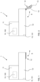
- FIG. 1 An embodiment of the extractor hood 1 according to the invention is shown in side view.
- the extractor hood 1 consists of the shown Embodiment comprising a hood body 10 and an extractor housing 11 extending upwards from the hood body 10.
- a fan 150 is arranged in the extractor housing 11 of the extractor hood 1, which represents a functional unit 15 of the extractor hood 1.
- the hood body 10 has a box shape, so that the extractor hood 1 can also be referred to as a box hood.
- a further functional unit 15 of the extractor hood 1 is arranged in the rear area of the hood body 10.
- This functional unit 15 represents a lighting device 151, via which, for example, a hob (not shown) located below the extractor hood 1 can be illuminated.
- a flap is shown, which in the embodiment shown represents an air guide element 12.
- the air guide element 12 is located in the Figure 1 shown first operating state on the underside of the hood body 10.
- the front end of the air guide element 12 is flush with the front of the hood body 10.
- the air guide element 12, which is also referred to as a flap, is pivotally attached to the hood body 10.
- the pivot axis, about which the air guide element 12 can be pivoted, lies horizontally and extends along the lower edge of the front of the hood body 12.
- the position of the air guide element 12, which in Figure 1 can also be referred to as a folded or closed position.
- the air guide element 12 can therefore be in the position shown in Figure 1 shown swivel direction S.
- an operating part 13 is arranged on the inside of the air guide element 12.
- the inside is the side of the air guide element 12 which is in the position in Figure 1 is directed upwards.
- a sensor 14 is arranged on the air guide element 12.
- the sensor 14 represents an acceleration sensor.
- the sensor 14 is integrated into the control unit 13.
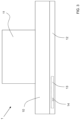
- the air guide element 12 extends across the entire width of the hood body 10.
- the operating part 13 is arranged laterally offset from the center of the air guide element 12.
- the operating part 13 can also be arranged in the middle of the width of the air guide element 12.
- the position or angle of inclination of the flap which can also be referred to as the glass screen or vapor trap flap, of a cooker hood can be detected.
- various actions such as turning the appliance's light on or off or triggering other actions, can be performed without the use of an electromechanical or contactless switch (limit switch, microswitch, reed contact, or similar).
- control panel of the extractor hood is equipped with an acceleration sensor (3g sensor), which is evaluated by a microcontroller or the existing control panel microcontroller.
- control panel electronics with an integrated 3g sensor can be provided on the glass screen/vapor trap flap, by means of which various angular positions of the glass screen/vapor trap flap can be detected and evaluated.
- the location, in particular the position or angle of inclination of the control panel attached to the glass screen/vapor trap flap, and thus also the angle of inclination of the glass screen/vapor trap flap can be calculated.
- various functions/actions can then be carried out according to the inclination/position of the glass screen/vapor trap flap, for example switching the light on and off, changing the fan speed depending on the flap position.
- the present invention has a number of advantages.
- no additional switch is required to detect the glass screen/vapor trap flap position. This means that no additional cabling is necessary, thus achieving cost savings.
- no additional mechanical parts such as actuating plungers, magnets for reed switches, and the like are required.
- the sensor for example, a 3g sensor, can be integrated into the operating electronics and evaluated by the control unit's microcontroller.
- various angular positions of the glass screen/vapor trap flap can be detected.
- An evaluation of the movement speed or acceleration is also possible. This means, for example, that a special action can be executed in the event of a sudden movement of the flap.
Landscapes
- Engineering & Computer Science (AREA)
- Chemical & Material Sciences (AREA)
- Combustion & Propulsion (AREA)
- Mechanical Engineering (AREA)
- General Engineering & Computer Science (AREA)
- Ventilation (AREA)
Applications Claiming Priority (2)
| Application Number | Priority Date | Filing Date | Title |
|---|---|---|---|
| DE102020205974.8A DE102020205974A1 (de) | 2020-05-12 | 2020-05-12 | Dunstabzugshaube und Verfahren zum Betreiben einer Dunstabzugshaube |
| PCT/EP2021/061839 WO2021228649A1 (de) | 2020-05-12 | 2021-05-05 | Dunstabzugshaube und verfahren zum betreiben einer dunstabzugshaube |
Publications (2)
| Publication Number | Publication Date |
|---|---|
| EP4150262A1 EP4150262A1 (de) | 2023-03-22 |
| EP4150262B1 true EP4150262B1 (de) | 2025-07-09 |
Family
ID=75977723
Family Applications (1)
| Application Number | Title | Priority Date | Filing Date |
|---|---|---|---|
| EP21726338.3A Active EP4150262B1 (de) | 2020-05-12 | 2021-05-05 | Dunstabzugshaube und verfahren zum betreiben einer dunstabzugshaube |
Country Status (7)
| Country | Link |
|---|---|
| US (1) | US20230182182A1 (es) |
| EP (1) | EP4150262B1 (es) |
| CN (1) | CN115485508A (es) |
| DE (1) | DE102020205974A1 (es) |
| ES (1) | ES3036141T3 (es) |
| PL (1) | PL4150262T3 (es) |
| WO (1) | WO2021228649A1 (es) |
Families Citing this family (2)
| Publication number | Priority date | Publication date | Assignee | Title |
|---|---|---|---|---|
| USD1049352S1 (en) * | 2022-02-14 | 2024-10-29 | Samsung Electronics Co., Ltd. | Kitchen extractor hood |
| US20240263017A1 (en) * | 2023-02-02 | 2024-08-08 | Whirlpool Corporation | Anti dripping coatings for hoods |
Citations (3)
| Publication number | Priority date | Publication date | Assignee | Title |
|---|---|---|---|---|
| CN102767857B (zh) * | 2012-07-04 | 2015-06-17 | 宁波方太厨具有限公司 | 一种挡烟屏自动开合的吸油烟机 |
| CN103851666B (zh) * | 2012-12-03 | 2018-06-19 | 海尔集团公司 | 油烟机及其控制方法 |
| CN110260381A (zh) * | 2019-07-15 | 2019-09-20 | 珠海格力电器股份有限公司 | 一种侧吸式吸油烟机 |
Family Cites Families (21)
| Publication number | Priority date | Publication date | Assignee | Title |
|---|---|---|---|---|
| US7469547B2 (en) * | 2004-09-09 | 2008-12-30 | Siemens Building Technologies, Inc. | Arrangement for detecting the position of a damper blade using a wireless communication sensor |
| TW200726945A (en) * | 2006-01-06 | 2007-07-16 | Guarder Ind Co Ltd | Non-contact hidden switch for smoke exhauster |
| WO2007112301A2 (en) * | 2006-03-24 | 2007-10-04 | Duke Manufacturing Co. | Vent system for cooking appliance |
| KR101535304B1 (ko) * | 2009-02-11 | 2015-07-08 | 엘지전자 주식회사 | 후드겸용 전자레인지 |
| US20110160914A1 (en) * | 2009-12-08 | 2011-06-30 | Sequest Systems Corp | Tilt sensor apparatus and method |
| EP2816295B1 (en) * | 2013-06-17 | 2019-06-05 | Lennox Industries Inc. | An HVAC system having a diagnostics controller associated therewith |
| CN104089315A (zh) * | 2014-07-21 | 2014-10-08 | 何祺晃 | 一种设置有智能隐形开关的油烟机 |
| EP3235546A1 (en) * | 2016-04-19 | 2017-10-25 | Belimo Holding AG | Damper blade with sensor |
| CN106123061A (zh) * | 2016-06-20 | 2016-11-16 | 广东美的厨房电器制造有限公司 | 吸油烟机和基于吸油烟机的通话控制方法 |
| CN105972657A (zh) * | 2016-06-20 | 2016-09-28 | 广东美的厨房电器制造有限公司 | 吸油烟机及其控制方法 |
| CN106091054A (zh) * | 2016-06-20 | 2016-11-09 | 广东美的厨房电器制造有限公司 | 吸油烟机及其控制装置和控制方法 |
| CN106123067A (zh) * | 2016-08-05 | 2016-11-16 | 广东万家乐燃气具有限公司 | 一种带有小挡板装置的油烟机 |
| CN206430219U (zh) * | 2016-12-15 | 2017-08-22 | 杭州老板电器股份有限公司 | 一种安全风门多角度控制油烟机 |
| WO2018132296A1 (en) * | 2017-01-13 | 2018-07-19 | Johnson Controls Technology Company | User control device with automatic mirroring and leveling system for semi-transparent display |
| CN112393307A (zh) * | 2017-11-06 | 2021-02-23 | 广东美的厨房电器制造有限公司 | 吸油烟机和开合面板组件的控制方法 |
| CN207797159U (zh) * | 2017-11-06 | 2018-08-31 | 广东美的厨房电器制造有限公司 | 吸油烟机 |
| CN108488855A (zh) * | 2018-03-20 | 2018-09-04 | 李秀荣 | 一种互联网智能抽油烟机 |
| CN208652662U (zh) * | 2018-08-04 | 2019-03-26 | 广东麦理杰电器有限公司 | 具有移动吸烟罩的抽油烟机 |
| CN109405015B (zh) * | 2018-11-08 | 2019-12-06 | 珠海格力电器股份有限公司 | 一种油烟机导烟板的控制方法、装置、油烟机及存储介质 |
| CN210320196U (zh) * | 2019-01-09 | 2020-04-14 | 博西家用电器(中国)有限公司 | 抽油烟机 |
| CN110594821B (zh) * | 2019-09-19 | 2021-02-26 | 宁波方太厨具有限公司 | 一种吸油烟机及其控制方法 |
-
2020
- 2020-05-12 DE DE102020205974.8A patent/DE102020205974A1/de active Pending
-
2021
- 2021-05-05 CN CN202180034853.5A patent/CN115485508A/zh active Pending
- 2021-05-05 EP EP21726338.3A patent/EP4150262B1/de active Active
- 2021-05-05 PL PL21726338.3T patent/PL4150262T3/pl unknown
- 2021-05-05 US US17/917,007 patent/US20230182182A1/en active Pending
- 2021-05-05 WO PCT/EP2021/061839 patent/WO2021228649A1/de not_active Ceased
- 2021-05-05 ES ES21726338T patent/ES3036141T3/es active Active
Patent Citations (3)
| Publication number | Priority date | Publication date | Assignee | Title |
|---|---|---|---|---|
| CN102767857B (zh) * | 2012-07-04 | 2015-06-17 | 宁波方太厨具有限公司 | 一种挡烟屏自动开合的吸油烟机 |
| CN103851666B (zh) * | 2012-12-03 | 2018-06-19 | 海尔集团公司 | 油烟机及其控制方法 |
| CN110260381A (zh) * | 2019-07-15 | 2019-09-20 | 珠海格力电器股份有限公司 | 一种侧吸式吸油烟机 |
Also Published As
| Publication number | Publication date |
|---|---|
| US20230182182A1 (en) | 2023-06-15 |
| ES3036141T3 (en) | 2025-09-15 |
| DE102020205974A1 (de) | 2021-12-02 |
| WO2021228649A1 (de) | 2021-11-18 |
| PL4150262T3 (pl) | 2025-12-01 |
| CN115485508A (zh) | 2022-12-16 |
| EP4150262A1 (de) | 2023-03-22 |
Similar Documents
| Publication | Publication Date | Title |
|---|---|---|
| DE102018103350B4 (de) | Bedienelement für einen Fahrzeuginnenraum | |
| EP4150262B1 (de) | Dunstabzugshaube und verfahren zum betreiben einer dunstabzugshaube | |
| EP4337892B1 (de) | Verfahren zum kühlen des austretenden wrasens oder dampfs aus dem garraum eines gargeräts und gargerät | |
| DE102014017833B4 (de) | Dunstabzugshaube | |
| DE102007012378A1 (de) | Hausgerät, insbesondere Backofen | |
| DE19814000C2 (de) | Dunstabzugshaube | |
| EP2210048B1 (de) | Dunstabzugsvorrichtung | |
| EP0892221A1 (de) | Dunstabzugseinrichtung mit Bewegungsmelder | |
| DE102021124881A1 (de) | Kochsystem und Verfahren zum Betreiben | |
| EP2089660B1 (de) | Dunstabzugshaube | |
| DE102010063860A1 (de) | Dunstabzugshaube | |
| EP3910247B1 (de) | Dunstabzugshaube mit bedienmodul | |
| DE202015102151U1 (de) | Elektrisch verstellbares Möbelstück | |
| EP2072908A1 (de) | Dunstabzugsvorrichtung | |
| EP4083518B1 (de) | Dunstabzugshaube | |
| EP4065777A1 (de) | Spülbecken mit einer abhängig von einem einflussfaktor automatisch verfahrbaren einsatzplatte, sowie verfahren | |
| DE19906318A1 (de) | Dunstabzugshaube | |
| DE102017103825B4 (de) | Vorrichtung zum Steuern eines Luftausströmers | |
| DE102012011775B4 (de) | Steuereinrichtung für einen Laborabzug und Laborabzug | |
| WO2023083503A1 (de) | Benutzerschnittstellengerät mit berührungsempfindlichem bildschirm | |
| DE102019106164A1 (de) | Eine Sanitärarmatur zum Abgeben von Wasser | |
| EP2112437B1 (de) | Dunstabzugsvorrichtung mit Wrasenleitblech | |
| DE102007061674A1 (de) | Dunstabzugsvorrichtung | |
| DE102021123760A1 (de) | Lüftungseinrichtung für eine Fahrgastzelle eines Kraftfahrzeuges | |
| DE2323229A1 (de) | Ueberwachungseinrichtung fuer die filteranordnung in dunstabzugshauben u. dgl |
Legal Events
| Date | Code | Title | Description |
|---|---|---|---|
| STAA | Information on the status of an ep patent application or granted ep patent |
Free format text: STATUS: UNKNOWN |
|
| STAA | Information on the status of an ep patent application or granted ep patent |
Free format text: STATUS: THE INTERNATIONAL PUBLICATION HAS BEEN MADE |
|
| PUAI | Public reference made under article 153(3) epc to a published international application that has entered the european phase |
Free format text: ORIGINAL CODE: 0009012 |
|
| STAA | Information on the status of an ep patent application or granted ep patent |
Free format text: STATUS: REQUEST FOR EXAMINATION WAS MADE |
|
| 17P | Request for examination filed |
Effective date: 20221212 |
|
| AK | Designated contracting states |
Kind code of ref document: A1 Designated state(s): AL AT BE BG CH CY CZ DE DK EE ES FI FR GB GR HR HU IE IS IT LI LT LU LV MC MK MT NL NO PL PT RO RS SE SI SK SM TR |
|
| DAV | Request for validation of the european patent (deleted) | ||
| DAX | Request for extension of the european patent (deleted) | ||
| STAA | Information on the status of an ep patent application or granted ep patent |
Free format text: STATUS: EXAMINATION IS IN PROGRESS |
|
| 17Q | First examination report despatched |
Effective date: 20240502 |
|
| GRAP | Despatch of communication of intention to grant a patent |
Free format text: ORIGINAL CODE: EPIDOSNIGR1 |
|
| STAA | Information on the status of an ep patent application or granted ep patent |
Free format text: STATUS: GRANT OF PATENT IS INTENDED |
|
| INTG | Intention to grant announced |
Effective date: 20250120 |
|
| GRAS | Grant fee paid |
Free format text: ORIGINAL CODE: EPIDOSNIGR3 |
|
| GRAA | (expected) grant |
Free format text: ORIGINAL CODE: 0009210 |
|
| STAA | Information on the status of an ep patent application or granted ep patent |
Free format text: STATUS: THE PATENT HAS BEEN GRANTED |
|
| AK | Designated contracting states |
Kind code of ref document: B1 Designated state(s): AL AT BE BG CH CY CZ DE DK EE ES FI FR GB GR HR HU IE IS IT LI LT LU LV MC MK MT NL NO PL PT RO RS SE SI SK SM TR |
|
| REG | Reference to a national code |
Ref country code: GB Ref legal event code: FG4D Free format text: NOT ENGLISH |
|
| REG | Reference to a national code |
Ref country code: CH Ref legal event code: EP |
|
| REG | Reference to a national code |
Ref country code: IE Ref legal event code: FG4D Free format text: LANGUAGE OF EP DOCUMENT: GERMAN |
|
| REG | Reference to a national code |
Ref country code: DE Ref legal event code: R096 Ref document number: 502021007971 Country of ref document: DE |
|
| REG | Reference to a national code |
Ref country code: ES Ref legal event code: FG2A Ref document number: 3036141 Country of ref document: ES Kind code of ref document: T3 Effective date: 20250915 |
|
| REG | Reference to a national code |
Ref country code: SE Ref legal event code: TRGR |
|
| REG | Reference to a national code |
Ref country code: NL Ref legal event code: MP Effective date: 20250709 |
|
| PG25 | Lapsed in a contracting state [announced via postgrant information from national office to epo] |
Ref country code: PT Free format text: LAPSE BECAUSE OF FAILURE TO SUBMIT A TRANSLATION OF THE DESCRIPTION OR TO PAY THE FEE WITHIN THE PRESCRIBED TIME-LIMIT Effective date: 20251110 |
|
| PG25 | Lapsed in a contracting state [announced via postgrant information from national office to epo] |
Ref country code: NL Free format text: LAPSE BECAUSE OF FAILURE TO SUBMIT A TRANSLATION OF THE DESCRIPTION OR TO PAY THE FEE WITHIN THE PRESCRIBED TIME-LIMIT Effective date: 20250709 |
|
| PG25 | Lapsed in a contracting state [announced via postgrant information from national office to epo] |
Ref country code: IS Free format text: LAPSE BECAUSE OF FAILURE TO SUBMIT A TRANSLATION OF THE DESCRIPTION OR TO PAY THE FEE WITHIN THE PRESCRIBED TIME-LIMIT Effective date: 20251109 |
|
| PG25 | Lapsed in a contracting state [announced via postgrant information from national office to epo] |
Ref country code: NO Free format text: LAPSE BECAUSE OF FAILURE TO SUBMIT A TRANSLATION OF THE DESCRIPTION OR TO PAY THE FEE WITHIN THE PRESCRIBED TIME-LIMIT Effective date: 20251009 |
|
| REG | Reference to a national code |
Ref country code: LT Ref legal event code: MG9D |
|
| PG25 | Lapsed in a contracting state [announced via postgrant information from national office to epo] |
Ref country code: FI Free format text: LAPSE BECAUSE OF FAILURE TO SUBMIT A TRANSLATION OF THE DESCRIPTION OR TO PAY THE FEE WITHIN THE PRESCRIBED TIME-LIMIT Effective date: 20250709 |
|
| PG25 | Lapsed in a contracting state [announced via postgrant information from national office to epo] |
Ref country code: HR Free format text: LAPSE BECAUSE OF FAILURE TO SUBMIT A TRANSLATION OF THE DESCRIPTION OR TO PAY THE FEE WITHIN THE PRESCRIBED TIME-LIMIT Effective date: 20250709 |
|
| PG25 | Lapsed in a contracting state [announced via postgrant information from national office to epo] |
Ref country code: GR Free format text: LAPSE BECAUSE OF FAILURE TO SUBMIT A TRANSLATION OF THE DESCRIPTION OR TO PAY THE FEE WITHIN THE PRESCRIBED TIME-LIMIT Effective date: 20251010 |
|
| PG25 | Lapsed in a contracting state [announced via postgrant information from national office to epo] |
Ref country code: LV Free format text: LAPSE BECAUSE OF FAILURE TO SUBMIT A TRANSLATION OF THE DESCRIPTION OR TO PAY THE FEE WITHIN THE PRESCRIBED TIME-LIMIT Effective date: 20250709 |
|
| PG25 | Lapsed in a contracting state [announced via postgrant information from national office to epo] |
Ref country code: BG Free format text: LAPSE BECAUSE OF FAILURE TO SUBMIT A TRANSLATION OF THE DESCRIPTION OR TO PAY THE FEE WITHIN THE PRESCRIBED TIME-LIMIT Effective date: 20250709 |
|
| PG25 | Lapsed in a contracting state [announced via postgrant information from national office to epo] |
Ref country code: RS Free format text: LAPSE BECAUSE OF FAILURE TO SUBMIT A TRANSLATION OF THE DESCRIPTION OR TO PAY THE FEE WITHIN THE PRESCRIBED TIME-LIMIT Effective date: 20251009 |