EP4150201B1 - Gasdosierventil für brennkraftmaschinen - Google Patents
Gasdosierventil für brennkraftmaschinen Download PDFInfo
- Publication number
- EP4150201B1 EP4150201B1 EP21720717.4A EP21720717A EP4150201B1 EP 4150201 B1 EP4150201 B1 EP 4150201B1 EP 21720717 A EP21720717 A EP 21720717A EP 4150201 B1 EP4150201 B1 EP 4150201B1
- Authority
- EP
- European Patent Office
- Prior art keywords
- valve
- shut
- gas
- control valve
- gaseous fuel
- Prior art date
- Legal status (The legal status is an assumption and is not a legal conclusion. Google has not performed a legal analysis and makes no representation as to the accuracy of the status listed.)
- Active
Links
Images

Classifications
-
- F—MECHANICAL ENGINEERING; LIGHTING; HEATING; WEAPONS; BLASTING
- F02—COMBUSTION ENGINES; HOT-GAS OR COMBUSTION-PRODUCT ENGINE PLANTS
- F02M—SUPPLYING COMBUSTION ENGINES IN GENERAL WITH COMBUSTIBLE MIXTURES OR CONSTITUENTS THEREOF
- F02M21/00—Apparatus for supplying engines with non-liquid fuels, e.g. gaseous fuels stored in liquid form
- F02M21/02—Apparatus for supplying engines with non-liquid fuels, e.g. gaseous fuels stored in liquid form for gaseous fuels
- F02M21/0218—Details on the gaseous fuel supply system, e.g. tanks, valves, pipes, pumps, rails, injectors or mixers
- F02M21/0248—Injectors
- F02M21/0251—Details of actuators therefor
- F02M21/0254—Electric actuators, e.g. solenoid or piezoelectric
-
- F—MECHANICAL ENGINEERING; LIGHTING; HEATING; WEAPONS; BLASTING
- F02—COMBUSTION ENGINES; HOT-GAS OR COMBUSTION-PRODUCT ENGINE PLANTS
- F02M—SUPPLYING COMBUSTION ENGINES IN GENERAL WITH COMBUSTIBLE MIXTURES OR CONSTITUENTS THEREOF
- F02M21/00—Apparatus for supplying engines with non-liquid fuels, e.g. gaseous fuels stored in liquid form
- F02M21/02—Apparatus for supplying engines with non-liquid fuels, e.g. gaseous fuels stored in liquid form for gaseous fuels
- F02M21/0218—Details on the gaseous fuel supply system, e.g. tanks, valves, pipes, pumps, rails, injectors or mixers
- F02M21/0248—Injectors
- F02M21/0257—Details of the valve closing elements, e.g. valve seats, stems or arrangement of flow passages
- F02M21/026—Lift valves, i.e. stem operated valves
- F02M21/0269—Outwardly opening valves, e.g. poppet valves
-
- F—MECHANICAL ENGINEERING; LIGHTING; HEATING; WEAPONS; BLASTING
- F02—COMBUSTION ENGINES; HOT-GAS OR COMBUSTION-PRODUCT ENGINE PLANTS
- F02M—SUPPLYING COMBUSTION ENGINES IN GENERAL WITH COMBUSTIBLE MIXTURES OR CONSTITUENTS THEREOF
- F02M21/00—Apparatus for supplying engines with non-liquid fuels, e.g. gaseous fuels stored in liquid form
- F02M21/02—Apparatus for supplying engines with non-liquid fuels, e.g. gaseous fuels stored in liquid form for gaseous fuels
- F02M21/0218—Details on the gaseous fuel supply system, e.g. tanks, valves, pipes, pumps, rails, injectors or mixers
- F02M21/0248—Injectors
- F02M21/0275—Injectors for in-cylinder direct injection, e.g. injector combined with spark plug
-
- F—MECHANICAL ENGINEERING; LIGHTING; HEATING; WEAPONS; BLASTING
- F02—COMBUSTION ENGINES; HOT-GAS OR COMBUSTION-PRODUCT ENGINE PLANTS
- F02M—SUPPLYING COMBUSTION ENGINES IN GENERAL WITH COMBUSTIBLE MIXTURES OR CONSTITUENTS THEREOF
- F02M21/00—Apparatus for supplying engines with non-liquid fuels, e.g. gaseous fuels stored in liquid form
- F02M21/02—Apparatus for supplying engines with non-liquid fuels, e.g. gaseous fuels stored in liquid form for gaseous fuels
- F02M21/0218—Details on the gaseous fuel supply system, e.g. tanks, valves, pipes, pumps, rails, injectors or mixers
- F02M21/0248—Injectors
- F02M21/0278—Port fuel injectors for single or multipoint injection into the air intake system
-
- Y—GENERAL TAGGING OF NEW TECHNOLOGICAL DEVELOPMENTS; GENERAL TAGGING OF CROSS-SECTIONAL TECHNOLOGIES SPANNING OVER SEVERAL SECTIONS OF THE IPC; TECHNICAL SUBJECTS COVERED BY FORMER USPC CROSS-REFERENCE ART COLLECTIONS [XRACs] AND DIGESTS
- Y02—TECHNOLOGIES OR APPLICATIONS FOR MITIGATION OR ADAPTATION AGAINST CLIMATE CHANGE
- Y02T—CLIMATE CHANGE MITIGATION TECHNOLOGIES RELATED TO TRANSPORTATION
- Y02T10/00—Road transport of goods or passengers
- Y02T10/10—Internal combustion engine [ICE] based vehicles
- Y02T10/30—Use of alternative fuels, e.g. biofuels
Definitions
- the invention relates to a gas metering valve, as is preferably used to meter gaseous fuel directly into a combustion chamber or an intake tract of an internal combustion engine.
- Gas valves for the metered metering of gases are state of the art, for example from DE 10 2014 225 922 A1 known.
- the gas valve disclosed here comprises a movable valve element that can be moved against the force of a spring element by an electromagnet and thereby opens and closes a connection between an inlet opening of the gas metering valve and an outlet opening. By switching the electromagnet on and off, the gas to be metered can be metered at the desired time and in the required amount.
- the sealing seat of the gas valve is located near the outlet opening, which on the one hand enables a relatively compact design and on the other hand facilitates precise control of the gas quantity.
- the gas metering valve When metering gaseous fuel directly into the combustion chamber of an internal combustion engine, the gas metering valve must be positioned close to the combustion chamber. The high combustion temperatures cause the gas metering valve to heat up considerably. If, for example, hydrogen is to be metered in, it is difficult to achieve reliable sealing with a metal sealing seat, especially since such a seal is essential for safety reasons over the entire service life of the gas metering valve, even if the internal combustion engine is not used for a long time. Therefore, the use of a plastic or elastomer seal is necessary, which, however, cannot be exposed to high temperatures without being damaged.
- the gas metering valve can be designed in such a way that the sealing seat coated with the elastomer is positioned relatively far from the outlet opening and thus from the combustion chamber. This leads to However, this leads to a higher susceptibility of the gas metering valve to flames from the combustion chamber flashing back into the gas metering valve, since the sealing seat is far from the combustion chamber, meaning that a relatively large volume of the gas metering valve remains directly connected to the combustion chamber, even when the gas metering valve is closed. In particular, if there are residues of the flammable gas in the gas metering valve, the flame front from the combustion chamber can spread into the gas metering valve and still lead to a strong thermal load on the sealing seat. In addition, a sealing seat far from the outlet opening of the gas metering valve makes it more difficult to meter the gaseous fuel precisely because of the relatively large volume between the sealing seat and the outlet opening.
- the invention is defined by the gas metering valve in claim 1 and by the method for operating the gas metering valve in claim 8. 1f
- the gas metering valve according to the invention has the advantage that reliable metering of the gaseous fuel is possible without the tightness of the gas metering valve being impaired even after a long downtime.
- the gas metering valve has a housing in which an inlet opening and an outlet opening for the gaseous fuel are formed.
- a gas chamber is formed in the housing, which connects the inlet opening to the outlet opening, so that gas flow from the inlet opening to the outlet opening is possible.
- An electrically operated shut-off valve is arranged in the gas chamber to interrupt the gas flow in the gas chamber.
- An electrically operated control valve is arranged between the shut-off valve and the outlet opening, with which the gas flow between the shut-off valve and the outlet opening can also be interrupted.
- the gas metering valve therefore comprises two electrically controllable valves with which the gas flow within the housing can be interrupted.
- the control valve in particular, i.e. the one of the two valves that is closer to the outlet opening and thus closer to the combustion chamber, can be closed to prevent heat from penetrating.
- the thermal load on the shut-off valve is thus significantly reduced. so that an elastomer seal can be easily installed on the shut-off valve, which ensures the desired tightness even when the internal combustion engine and thus the gas metering valve are not in use for a long time.
- the shut-off valve comprises a shut-off valve element which cooperates with a corresponding shut-off valve seat to interrupt the gas flow within the gas space.
- the control valve also advantageously comprises a movable control valve element which cooperates with a control valve seat to interrupt the gas flow, with both valves preferably being designed as electromagnetic valves.
- the check valve seat and/or the check valve element is preferably coated with a plastic, preferably an elastomer, in order to achieve a gas-tight seal, even when dosing hydrogen gas, which practically cannot be completely sealed by a pure metal-metal seal.
- a plastic preferably an elastomer
- complete sealing is not necessary between each injection of gaseous fuel. If another injection follows within a short time interval, a certain leak can be tolerated, since the small amount of gaseous fuel that flows out is pressed into the combustion chamber with the next injection and the function of the internal combustion engine is not impaired.
- An elastomer coating of the control valve is therefore not necessary; instead, a robust and hard material pairing between the control valve element and the control valve seat can be selected in order to keep wear in this area as low as possible.
- the shut-off valve is preferably opened before the start of metering, while the control valve only opens with a time delay.
- the metal-to-metal seal of the control valve is also sufficiently tight for a short-term interruption of the gas flow, so that the precise and timely metering of the gaseous fuel can also take place exclusively via the control valve, while the shut-off valve is kept constantly open. Only after a longer downtime, i.e. when no gaseous fuel is to be metered for a longer period of time, is the shut-off valve also closed to completely seal the gas metering valve.
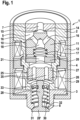
- a first gas metering valve according to the invention is shown in longitudinal section, with only the essential parts of the gas metering valve being shown. In particular, the connection lines for supplying the gaseous fuel and the electrical connections are not shown.
- the gas metering valve comprises a housing 1 which comprises a valve body 2 and a nozzle body 3 which are clamped against one another in a gas-tight manner by a clamping nut 4.
- a gas chamber 5 is formed in the housing 1 and has an inlet opening 7 and an outlet opening 8, thus enabling gas to flow from the inlet opening 7 to the outlet opening 8.
- a check valve 10 is arranged in the gas chamber 5, which is designed as an electromagnetic valve and comprises a check valve element 11 which can be moved by means of a first electromagnet 12 against the force of a closing spring 17.
- the check valve 10 is designed to interrupt the gas flow within the gas chamber 5 when the check valve element 11 rests against a check valve seat 14.
- the check valve seat 14 is designed for this purpose at the upper end of the gas chamber 5 in the drawing and surrounds the inlet opening 7 through which the gaseous fuel flows into the gas chamber 5. If the check valve element 11 rests against the check valve seat 14, the inlet opening 7 is closed off from the gas chamber 5 so that no gas can flow from the inlet opening 7 into the gas chamber 5.
- the check valve element 11 By energizing the electromagnet 12, the check valve element 11 can be pulled away from the check valve seat 14 so that a flow cross-section is released between the check valve element 11 and the housing 2, through which the gas flows from the inlet opening into the gas chamber 5.
- the further flow path is defined by two or more connecting bores 16 which are formed in the check valve element 11 and which open into a longitudinal bore 18 which runs centrally in the check valve element 11, wherein the closing spring 17 is also arranged in this longitudinal bore 18.
- the electromagnet 12 surrounds the valve body 2 on its outside, with the valve body 2 or parts thereof acting as a magnetic core to concentrate the magnetic field specifically in the area of the shut-off valve element 11 and thus enable rapid switching.
- the stroke stop for the shut-off valve element 11 is formed by an intermediate disk 20 which has a central opening 21 through which the gas can continue to flow within the gas chamber 5.
- the intermediate disk 20 lies on a shoulder within the gas chamber 5 and is held in place there by the pre-tensioning force of the closing spring 17.
- An elastomer seal 15 is arranged on the shut-off valve element 11 in the area of the sealing surface that interacts with the shut-off valve seat 14.
- the seal is made of a flexible plastic and thus adapts elastically to the sealing surfaces.
- This elastomer seal 15 ensures a gas-tight seal on the shut-off valve seat 14, even if the gas metering valve is not used for a long time and the gas is constantly present at the inlet opening under the intended injection pressure.
- a control valve 25 Downstream of the shut-off valve 10 and the intermediate disk 20, a control valve 25 is arranged in the gas chamber 5, which, like the shut-off valve 10, can interrupt the gas flow within the gas chamber 5 towards the outlet opening 8.
- the control valve 25 comprises a control valve element 26, which comprises a magnet armature 27 and a closing element 28, which are connected to one another and thus always move together.
- the magnet armature 27 is essentially cylindrical and has two or more longitudinal bores 35 through which the gaseous fuel can flow in the direction of the outlet opening 8, the outlet opening being located at the end of the valve body 2, which forms the combustion chamber-side end of the housing 1.
- the closing element 28 is piston-shaped and has a closing plate 28' on its combustion chamber-side end, i.e.
- the closing element 28 is surrounded by a spring 30 which is arranged under pressure preload between a shoulder 32 in the nozzle body 3 and a support disk 33, wherein the support disk 33 is firmly connected to the closing element 28.
- the preload force of the spring 30 presses the control valve element 26 against the control valve seat 31 and thus closes the outlet opening 8.
- the electromagnet 29 is energized, which pulls the control valve element 26 against the force of the spring 30 from the control valve seat 31 in the direction of the combustion chamber, i.e. out of the gas chamber 5. This opens up a flow cross-section between the closing plate 28' and the control valve seat 31, through which the gaseous fuel flows out.
- the spring 30 presses the control valve element 26 back into its closed position.
- FIG. 2 which is shown in the same representation as Fig. 1 shows a gas metering valve in which the shut-off valve element 11' is different from the first embodiment of the Fig. 1 is arranged rotated by 180°.
- the closing spring 17' is arranged here between the inlet opening 7 and the check valve element 11' under prestress and presses the check valve element 11' against the check valve seat 14', which is formed on the central opening 21 of the intermediate disk 20.
- an elastomer seal 15' is also present so that the check valve element 11' closes the central opening 21 in a gas-tight manner.
- the shut-off valve element 11' opens in the embodiment according to Fig. 2 by the action of the electromagnet 12 against the flow direction of the gaseous fuel. If an overpressure occurs in which an impermissibly high pressure difference of the gaseous fuel occurs between the inlet opening 7 and the outlet opening 8, the gas flow supports the force of the closing spring 17' and presses the shut-off valve element 11' into its closed position. This prevents an uncontrolled release of gaseous fuel into the system to be supplied, for example a combustion chamber of an internal combustion engine.
- Both electromagnets 12, 29 can be controlled independently of one another, so that the shut-off valve 10 and the control valve 25 can be opened and closed independently of one another.
- the control valve 25 is sufficient for the actual metering of the gaseous fuel into the combustion chamber, since a completely tight seal is generally not necessary between injections that are in close succession.
- the gas metering valve can therefore be operated in such a way that the shut-off valve 10 is opened at the start of the metering and only then the control valve 25, which determines the amount of gaseous fuel by its opening time and its opening duration. If further gaseous fuel is to be released in a short time, only the control valve 25 can be closed and opened again, while the shut-off valve 10 remains constantly open.
- the shut-off valve 10 is only closed after a longer metering break in order to achieve the necessary absolute tightness.
- the shut-off valve 10 therefore does not have to be highly dynamic, which means that a relatively simple electromagnetic valve can be used here, which only comprises a small electromagnet and therefore requires little energy.
- the control valve 25 does not have to meet high sealing requirements, hard and low-wear materials can be used in the area of the control valve seat, which can withstand high loads and have a long service life.
Landscapes
- Engineering & Computer Science (AREA)
- Chemical & Material Sciences (AREA)
- Chemical Kinetics & Catalysis (AREA)
- General Chemical & Material Sciences (AREA)
- Oil, Petroleum & Natural Gas (AREA)
- Combustion & Propulsion (AREA)
- Mechanical Engineering (AREA)
- General Engineering & Computer Science (AREA)
- Analytical Chemistry (AREA)
- Magnetically Actuated Valves (AREA)
- Fuel-Injection Apparatus (AREA)
Description
- Die Erfindung betrifft ein Gasdosierventil, wie es vorzugsweise Verwendung findet, um gasförmigen Kraftstoff direkt in einen Brennraum oder einen Ansaugtrakt einer Brennkraftmaschine einzudosieren.
- Gasventile zur dosierten Zumessungen von Gasen sind aus dem Stand der Technik zum Beispiel aus der
DE 10 2014 225 922 A1 bekannt. Das hier offenbarte Gasventil umfasst ein bewegliches Ventilelement, das gegen die Kraft eines Federelements durch einen Elektromagneten bewegbar ist und dadurch eine Verbindung zwischen einer Einlassöffnung des Gasdosierventils und einer Auslassöffnung öffnet und schließt. Durch An- und Abschalten des Elektromagneten kann das zu dosierende Gas zum gewünschten Zeitpunkt und in der benötigten Menge dosiert werden. Der Dichtsitz des Gasventils befindet sich nahe der Auslassöffnung, was zum einen einen relativ kompakten Aufbau ermöglicht und zum anderen eine präzise Steuerung der Gasmenge erleichtert. - Bei der Zumessung von gasförmigem Kraftstoff direkt in einen Brennraum einer Brennkraftmaschine muss das Gasdosierventil nahe dem Brennraum angeordnet werden. Durch die hohen Verbrennungstemperaturen kommt es so zu einer starken Erwärmung des Gasdosierventils. Soll beispielsweise Wasserstoff eindosiert werden, so kann eine zuverlässige Abdichtung durch einen metallischen Dichtsitz nur schwer erreicht werden, zumal eine solche Abdichtung über die gesamte Lebensdauer des Gasdosierventils aus Sicherheitsgründen unabdingbar ist, auch dann, wenn die Brennkraftmaschine längere Zeit ungenutzt ist. Deshalb ist die Verwendung einer Kunststoff- oder Elastomerdichtung notwendig, die jedoch keinen hohen Temperaturen ausgesetzt werden kann, ohne beschädigt zu werden. Um die Temperaturen am Dichtsitz zu begrenzen, kann das Gasdosierventil so konstruiert werden, dass der mit dem Elastomer beschichtete Dichtsitz relativ weit von der Auslassöffnung und damit vom Brennraum angeordnet ist. Dies führt jedoch zu einer höheren Anfälligkeit des Gasdosierventils gegenüber einem Rückschlagen der Flammen aus dem Brennraum in das Gasdosierventil, da wegen des brennraumfernen Dichtsitzes ein relativ großes Volumen des Gasdosierventils direkt mit dem Brennraum verbunden bleibt, auch dann, wenn das Gasdosierventil geschlossen ist. Insbesondere dann, wenn sich Reste des brennbaren Gases im Gasdosierventil befinden, kann sich die Flammenfront des Brennraums in das Gasdosierventil ausbreiten und dort trotzdem zu einer starken thermischen Belastung am Dichtsitz führen. Darüber hinaus erschwert ein weit von der Auslassöffnung des Gasdosierventils befindlicher Dichtsitz eine exakte Dosierung des gasförmigen Kraftstoffs wegen des relativ großen Volumens zwischen Dichtsitz und Auslassöffnung.
- Ein weiteres Gasdosierventil ist aus
EP 1 336 738 A2 bekannt. 1f - Vorteile der Erfindung
- Die Erfindung wird durch das Gasdosierventil in Anspruch 1 und durch das Verfahren zum Betrieb des Gasdosierventils in Anspruch 8 definiert. 1f
- Das erfindungsgemäße Gasdosierventil weist demgegenüber den Vorteil auf, dass eine zuverlässige Dosierung des gasförmigen Kraftstoffs möglich ist, ohne dass die Dichtheit des Gasdosierventils auch bei längerer Standzeit beeinträchtigt ist. Dazu weist das Gasdosierventil ein Gehäuse auf, in dem eine Einlassöffnung und eine Auslassöffnung für den gasförmigen Kraftstoff ausgebildet sind. Im Gehäuse ist ein Gasraum ausgebildet, der die Einlassöffnung mit der Auslassöffnung verbindet, so dass eine Gasströmung von der Einlassöffnung zur Auslassöffnung möglich ist. Im Gasraum ist ein elektrisch betriebenes Sperrventil zur Unterbrechung der Gasströmung im Gasraum angeordnet. Zwischen dem Sperrventil und der Auslassöffnung ist ein elektrisch betriebenes Steuerventil angeordnet, mit dem zusätzlich die Gasströmung zwischen dem Sperrventil und der Auslassöffnung unterbrochen werden kann.
- Das Gasdosierventil umfasst also zwei elektrisch steuerbare Ventile, mit denen der Gasstrom innerhalb des Gehäuses unterbrochen werden kann. Nach Beendigung der Gasdosierung kann damit insbesondere das Steuerventil, also das der beiden Ventile, das sich näher an der Auslassöffnung und damit näher am Brennraum befindet, geschlossen werden, um das Eindringen von Wärme zu verhindern. Die thermische Belastung des Sperrventils wird damit deutlich verringert, so dass am Sperrventil eine Elastomerdichtung problemlos eingesetzt werden kann, was die gewünschte Dichtheit auch bei längerer Standzeit der Brennkraftmaschine und damit des Gasdosierventils gewährleistet.
- In einer vorteilhaften Ausgestaltung umfasst das Sperrventil ein Sperrventilelement, das mit einem entsprechenden Sperrventilsitz zum Unterbrechen der Gasströmung innerhalb des Gasraums zusammenwirkt. Auch das Steuerventil umfasst in vorteilhafter Weise ein bewegliches Steuerventilelement, das mit einem Steuerventilsitz zum Unterbrechen des Gasstroms zusammenwirkt, wobei beide Ventile vorzugsweise als elektromagnetische Ventile ausgebildet sind.
- Der Sperrventilsitz und/oder das Sperrventilelement ist vorzugsweise mit einem Kunststoff, vorzugsweise einem Elastomer, beschichtet um eine gasdichte Abdichtung zu erreichen, auch bei der Dosierung von Wasserstoffgas, das durch eine reine Metall-Metall-Dichtung praktisch nicht vollständig abgedichtet werden kann. Eine vollständige Abdichtung ist jedoch nicht zwischen jeder Eindüsung von gasförmigem Kraftstoff nötig. Folgt in zeitlich geringem Abstand eine weitere Eindüsung, so kann eine gewisse Undichtheit toleriert werden, da die so ausströmende geringe Menge an gasförmigem Kraftstoff mit der nächsten Eindüsung in den Brennraum gedrückt wird und die Funktion der Brennkraftmaschine dadurch nicht beeinträchtigt wird. Deshalb ist eine Elastomerbeschichtung des Steuerventils nicht notwendig, vielmehr kann hier eine robuste und harte Materialpaarung zwischen dem Steuerventilelement und dem Steuerventilsitz gewählt werden, um den Verschleiß in diesem Bereich so gering wie möglich zu halten.
- Da beide Ventile vorzugsweise durch einen eigenen Elektromagneten unabhängig voneinander geschaltet werden können, können beliebige Verfahren zum Betreiben des Gasdosierventils umgesetzt werden. Dabei wird vorzugsweise vor Beginn der Dosierung das Absperrventil geöffnet, während das Steuerventil erst mit einem zeitlichen Versatz öffnet. Auch die Metall-Metall-Dichtung des Steuerventils ist für eine kurzzeitige Unterbrechung der Gasströmung ausreichend dicht, so dass die genaue und zeitlich präzise Eindosierung des gasförmigen Kraftstoffs auch ausschließlich über das Steuerventil erfolgen kann, während das Sperrventil ständig offen gehalten wird. Erst bei längerer Standzeit, also wenn für längere Zeit kein gasförmiger Kraftstoff dosiert werden soll, wird auch das Sperrventil geschlossen, um das Gasdosierventil vollkommen abzudichten.
- In der Zeichnung sind zwei Ausführungsbeispiele des erfindungsgemäßen Gasdosierventils dargestellt. Es zeigt
- Fig. 1
- ein erfindungsgemäßes Gasdosierventil im Längsschnitt, wobei nur die wesentlichen Bereiche dargestellt sind, und
- Fig. 2
- ein weiteres Ausführungsbeispiel in der gleichen Darstellung wie
Fig. 1 . - In
Fig. 1 ist ein erstes erfindungsgemäßes Gasdosierventil im Längsschnitt dargestellt, wobei nur die wesentlichen Teile des Gasdosierventils gezeigt sind. Insbesondere die Anschlussleitungen für die Zuführung des gasförmigen Kraftstoffs und die elektrischen Anschlüsse sind nicht dargestellt. Das Gasdosierventil umfasst ein Gehäuse 1, das einen Ventilkörper 2 und einen Düsenkörper 3 umfasst, die durch eine Spannmutter 4 gegeneinander gasdicht verspannt sind. Im Gehäuse 1 ist ein Gasraum 5 ausgebildet, der eine Einlassöffnung 7 und eine Auslassöffnung 8 aufweist und so eine Gasströmung von der Einlassöffnung 7 zur Auslassöffnung 8 ermöglicht. Im Gasraum 5 ist ein Sperrventil 10 angeordnet, das als elektromagnetisches Ventil ausgebildet ist und ein Sperrventilelement 11 umfasst, das mittels eines ersten Elektromagneten 12 gegen die Kraft einer Schließfeder 17 bewegbar ist. Das Sperrventil 10 ist dazu ausgebildet, den Gasstrom innerhalb des Gasraums 5 zu unterbrechen, wenn das Sperrventilelement 11 an einem Sperrventilsitz 14 anliegt. Der Sperrventilsitz 14 ist dazu an dem in der Zeichnung oberen Ende des Gasraums 5 ausgebildet und umgibt die Einlassöffnung 7, durch die der gasförmige Kraftstoff in den Gasraum 5 strömt. Liegt das Sperrventilelement 11 am Sperrventilsitz 14 an, so wird die Einlassöffnung 7 gegen den Gasraum 5 verschlossen, so dass keine Gasströmung von der Einlassöffnung 7 in den Gasraum 5 erfolgen kann. Durch Bestromen des Elektromagneten 12 kann das Sperrventilelement 11 vom Sperrventilsitz 14 weggezogen werden, so dass zwischen dem Sperrventilelement 11 und dem Gehäuse 2 ein Strömungsquerschnitt freigegeben wird, durch den das Gas aus der Einlassöffnung in den Gasraum 5 strömt. Dabei ist der weitere Strömungsweg durch zwei oder mehrere Verbindungsbohrungen 16 gegeben, die im Sperrventilelement 11 ausgebildet sind und die in eine Längsbohrung 18 münden, die mittig im Sperrventilelement 11 verläuft, wobei auch die Schließfeder 17 in dieser Längsbohrung 18 angeordnet ist. - Der Elektromagnet 12 umgibt den Ventilkörper 2 an seiner Außenseite, wobei der Ventilkörper 2 oder Teile davon als Magnetkern wirken, um das Magnetfeld gezielt im Bereich des Sperrventilelements 11 zu konzentrieren und damit ein schnelles Schalten zu ermöglichen. Der Hubanschlag für das Sperrventilelement 11 wird durch eine Zwischenscheibe 20 gebildet, die eine zentrale Öffnung 21 aufweist, durch die das Gas weiter innerhalb des Gasraums 5 strömen kann. Dabei liegt die Zwischenscheibe 20 an einem Absatz innerhalb des Gasraums 5 und wird durch die Vorspannkraft der Schließfeder 17 dort ortsfest gehalten.
- Am Sperrventilelement 11 ist im Bereich der Dichtfläche, die mit dem Sperrventilsitz 14 zusammenwirkt, eine Elastomerdichtung 15 angeordnet, die aus einem flexiblen Kunststoff besteht und sich damit elastisch an die Dichtflächen anpasst. Diese Elastomerdichtung 15 sorgt für eine gasdichte Abdichtung am Sperrventilsitz 14 auch dann, wenn das Gasdosierventil längere Zeit nicht verwendet wird und das Gas ständig unter dem vorgesehenen Eindüsdruck an der Einlassöffnung anliegt.
- Stromabwärts des Sperrventils 10 und der Zwischenscheibe 20 ist im Gasraum 5 ein Steuerventil 25 angeordnet, das ebenso wie das Sperrventil 10 die Gasströmung innerhalb des Gasraums 5 zur Auslassöffnung 8 hin unterbrechen kann. Das Steuerventil 25 umfasst ein Steuerventilelement 26, das einen Magnetanker 27 und ein Schließelement 28 umfasst, die miteinander verbunden sind und sich damit stets zusammen bewegen. Der Magnetanker 27 ist im Wesentlichen zylinderförmig ausgebildet und weist zwei oder mehr Längsbohrungen 35 auf, durch die der gasförmige Kraftstoff in Richtung der Auslassöffnung 8 strömen kann, wobei sich die Auslassöffnung am Ende des Ventilkörpers 2 befindet, der das brennraumseitige Ende des Gehäuses 1 bildet. Das Schließelement 28 ist kolbenförmig ausgebildet und weist an seinem brennraumseitigen, das heißt in der Zeichnung unteren Ende, einen Schließteller 28' auf, an der eine Dichtfläche ausgebildet ist, mit der der Schließteller mit einem Steuerventilsitz 31 zusammenwirkt, der an der Außenseite des Düsenkörpers 3 die Auslassöffnung 8 umgebend ausgebildet ist. Das Schließelement 28 ist von einer Feder 30 umgeben, die unter Druckvorspannung zwischen einem Absatz 32 im Düsenkörper 3 und einer Stützscheibe 33 angeordnet ist, wobei die Stützscheibe 33 fest mit dem Schließelement 28 verbunden ist. Durch die Vorspannkraft der Feder 30 wird das Steuerventilelement 26 gegen den Steuerventilsitz 31 gedrückt und verschließt so die Auslassöffnung 8.
- Zum Öffnen des Steuerventils 25 wird der Elektromagnet 29 bestromt, der das Steuerventilelement 26 gegen die Kraft der Feder 30 vom Steuerventilsitz 31 in Richtung des Brennraums zieht, also aus dem Gasraum 5 heraus. Dadurch wird zwischen dem Schließteller 28' und dem Steuerventilsitz 31 ein Strömungsquerschnitt aufgesteuert, durch den der gasförmige Kraftstoff ausströmt. Nach Beendigung der Bestromung des Elektromagneten 29 drückt die Feder 30 das Steuerventilelement 26 zurück in seine Schließstellung.
- Ein weiteres Ausführungsbeispiel ist in
Fig. 2 dargestellt, das in derselben Darstellung wieFig. 1 ein Gasdosierventil zeigt, bei dem das Sperrventilelement 11' gegenüber dem ersten Ausführungsbeispiel derFig. 1 um 180° gedreht angeordnet ist. Entsprechend ist die Schließfeder 17' hier zwischen der Einlassöffnung 7 und dem Sperrventilelement 11' unter Vorspannung angeordnet und drückt das Sperrventilelement 11' gegen den Sperrventilsitz 14', der an der zentralen Öffnung 21 der Zwischenscheibe 20 ausgebildet ist. Auch bei diesem Ausführungsbeispiel ist eine Elastomerdichtung 15' vorhanden, damit das Sperrventilelement 11' die zentrale Öffnung 21 gasdicht verschließt. - Das Sperrventilelement 11' öffnet beim Ausführungsbeispiel nach
Fig. 2 durch die Wirkung des Elektromagneten 12 gegen die Fließrichtung des gasförmigen Kraftstoffs. Kommt es zu einem Überdruckfall, bei dem zwischen der Einlassöffnung 7 und der Auslassöffnung 8 eine unzulässig hohe Druckdifferenz des gasförmigen Kraftstoffs auftritt, so unterstützt der Gasfluss die Kraft der Schließfeder 17' und drückt das Sperrventilelement 11' in seine Schließstellung. Dies verhindert eine unkontrollierte Abgabe von gasförmigem Kraftstoff in das zu versorgende System, beispielsweise einen Brennraum einer Brennkraftmaschine. - Beide Elektromagneten 12, 29 lassen sich unabhängig voneinander ansteuern, so dass das Sperrventil 10 und das Steuerventil 25 unabhängig voneinander geöffnet und geschlossen werden können. Für die eigentliche Eindosierung des gasförmigen Kraftstoffs in den Brennraum ist das Steuerventil 25 ausreichend, da zwischen zeitlich eng aufeinanderfolgenden Eindüsungen in der Regel kein vollständig dichter Verschluss notwendig ist. Das Gasdosierventil kann also in der Weise betrieben werden, dass zu Beginn der Eindosierung das Sperrventil 10 geöffnet wird und erst anschließend das Steuerventil 25, das durch seinen Öffnungszeitpunkt und seine Öffnungsdauer die Menge des gasförmigen Kraftstoffs bestimmt. Soll zeitnah eine weitere Abgabe von gasförmigem Kraftstoff erfolgen, so kann auch nur das Steuerventil 25 geschlossen und wieder geöffnet werden, während das Sperrventil 10 ständig geöffnet bleibt. Erst bei einer längeren Dosierpause wird auch das Sperrventil 10 geschlossen, um die notwendige absolute Dichtheit zu erreichen. Das Sperrventil 10 muss deshalb keine hohe Dynamik aufweisen, das heißt, es kann hier ein relativ einfaches elektromagnetisches Ventil verwendet werden, das nur einen kleinen Elektromagneten umfasst und deshalb mit wenig Energie auskommt. Da das Steuerventil 25 keine hohen Abdichtungsanforderungen erfüllen muss, können hier harte und verschleißarme Materialien im Bereich des Steuerventilsitzes verwendet werden, die hohen Belastungen standhalten und die eine hohe Lebensdauer aufweisen.
Claims (9)
- Gasdosierventil für gasförmigen Kraftstoff, mit einem Gehäuse (1), in dem eine Einlassöffnung (7) und eine Auslassöffnung (8) für den gasförmigen Kraftstoff ausgebildet sind, und mit einem Gasraum (5), der im Gehäuse (1) ausgebildet ist und der die Einlassöffnung (7) mit der Auslassöffnung (8) verbindet, so dass eine Gasströmung von der Einlassöffnung (7) zur Auslassöffnung (8) möglich ist, und mit einem Sperrventil (10) zur Unterbrechung der Gasströmung im Gasraum (5), wobei im Gasraum (5) zwischen dem Sperrventil (10) und der Auslassöffnung (8) ein elektrisch betriebenes Steuerventil (25) angeordnet ist, mit dem die Gasströmung zwischen dem Sperrventil (10) und der Auslassöffnung (8) unterbrochen werden kann,wobei das Sperrventil (10) mittels einem elektrischen Aktor (12) steuerbar ist, wobei es sich bei dem elektrischen Aktor (12) um einen ersten Elektromagneten (12) handelt, wobeidas Sperrventil (10) als elektromagnetisches Steuerventil ausgebildet ist und das Sperrventil (10) mittels des ersten Elektromagneten (12) betätigt wird,dadurch gekennzeichnet, dass das Steuerventil (25) als elektromagnetisches Steuerventil ausgebildet ist und dassdas Steuerventil (25) mittels eines zweiten Elektromagneten (28) betätigt wird, wobei beide Elektromagnete unabhängig voneinander ansteuerbar sind.
- Gasdosierventil nach Anspruch 1, dadurch gekennzeichnet, dass das Sperrventil (10) ein bewegliches Sperrventilelement (11; 11') umfasst, das mit einem Sperrventilsitz (14) zum Unterbrechen der Gasströmung im Gasraum (5) zusammenwirkt.
- Gasdosierventil nach Anspruch 2, dadurch gekennzeichnet, dass das Sperrventilelement (11; 11') von einer Schließfeder (17; 17') in Richtung des Sperrventilsitzes (14; 14') mit einer Schließkraft beaufschlagt ist, so dass das Sperrventil (10) bei Aktivierung des elektrischen Aktors (12) gegen die Kraft der Schließfeder bewegt wird.
- Gasdosierventil nach Anspruch 2, dadurch gekennzeichnet, dass das Sperrventil (10) in Strömungsrichtung des gasförmigen Kraftstoffs öffnet.
- Gasdosierventil nach Anspruch 2, dadurch gekennzeichnet, dass das Sperrventil (10) gegen die Strömungsrichtung des gasförmigen Kraftstoffs öffnet.
- Gasdosierventil nach einem der Ansprüche 2 bis 5, dadurch gekennzeichnet, dass das Sperrventilelement (11; 11') zumindest in dem Bereich, der mit dem Sperrventilsitz (14; 14') zusammenwirkt, und/oder der Steuerventilsitz (14; 14') mit einem Kunststoff, insbesondere mit einem Elastomer, beschichtet ist.
- Gasdosierventil nach einem der Ansprüche 1 bis 6, dadurch gekennzeichnet, dass das Steuerventil (25) ein bewegliches Steuerventilelement (26) umfasst, das mit einem Steuerventilsitz (30) zum Unterbrechen der Gasströmung im Gasraum (5) zusammenwirkt.
- Verfahren zum Betreiben eines Gasdosierventils nach einem der Ansprüche 1 bis 7, dadurch gekennzeichnet, dass zur Dosierung des gasförmigen Kraftstoffs zuerst das Sperrventil (10) geöffnet wird und zeitlich nachfolgend das Steuerventil (25).
- Verfahren nach Anspruch 8, dadurch gekennzeichnet, dass das Sperrventil (10) während des Betriebs des Gasdosierventils geöffnet bleibt und die Eindosierung des gasförmigen Kraftstoffs ausschließlich durch das Steuerventil (25) geschieht.
Applications Claiming Priority (3)
| Application Number | Priority Date | Filing Date | Title |
|---|---|---|---|
| DE102020206111 | 2020-05-14 | ||
| DE102020214170.3A DE102020214170A1 (de) | 2020-05-14 | 2020-11-11 | Gasdosierventil für Brennkraftmaschinen |
| PCT/EP2021/060072 WO2021228496A1 (de) | 2020-05-14 | 2021-04-19 | Gasdosierventil für brennkraftmaschinen |
Publications (2)
| Publication Number | Publication Date |
|---|---|
| EP4150201A1 EP4150201A1 (de) | 2023-03-22 |
| EP4150201B1 true EP4150201B1 (de) | 2025-01-29 |
Family
ID=78280668
Family Applications (1)
| Application Number | Title | Priority Date | Filing Date |
|---|---|---|---|
| EP21720717.4A Active EP4150201B1 (de) | 2020-05-14 | 2021-04-19 | Gasdosierventil für brennkraftmaschinen |
Country Status (6)
| Country | Link |
|---|---|
| EP (1) | EP4150201B1 (de) |
| JP (1) | JP7464754B2 (de) |
| KR (1) | KR20230011336A (de) |
| CN (1) | CN115605679A (de) |
| DE (1) | DE102020214170A1 (de) |
| WO (1) | WO2021228496A1 (de) |
Families Citing this family (3)
| Publication number | Priority date | Publication date | Assignee | Title |
|---|---|---|---|---|
| DE102020215881A1 (de) | 2020-12-15 | 2022-06-15 | Robert Bosch Gesellschaft mit beschränkter Haftung | Gasdosierventil |
| DE102021213832A1 (de) | 2021-12-06 | 2023-06-07 | Robert Bosch Gesellschaft mit beschränkter Haftung | Gasventil zur dosierten Abgabe eines gasförmigen Brennstoffs und Verfahren zum Betreiben eines solchen Gasventils |
| DE102021214328A1 (de) | 2021-12-14 | 2023-06-15 | Robert Bosch Gesellschaft mit beschränkter Haftung | Gasventil zur dosierten Abgabe eines gasförmigen Brennstoffs und Verfahren zum Betreiben eines solchen Gasventils |
Citations (1)
| Publication number | Priority date | Publication date | Assignee | Title |
|---|---|---|---|---|
| EP1336738B1 (de) * | 2002-02-14 | 2006-12-13 | Bayerische Motoren Werke Aktiengesellschaft | Einrichtung zum Einbringen von Kraftstoff zur Verbrennung in einer Brennkraftmaschine |
Family Cites Families (7)
| Publication number | Priority date | Publication date | Assignee | Title |
|---|---|---|---|---|
| US6938634B2 (en) * | 2003-05-30 | 2005-09-06 | Robertshaw Controls Company | Fuel control mechanism and associated method of use |
| JP2010096073A (ja) * | 2008-10-16 | 2010-04-30 | Nikki Co Ltd | ガス燃料用インジェクタ |
| JP2014005729A (ja) * | 2012-06-21 | 2014-01-16 | Denso Corp | 気体燃料用圧力制御装置 |
| JP2014062477A (ja) * | 2012-09-20 | 2014-04-10 | Nikki Co Ltd | ガス燃料供給制御装置 |
| DE102014224341A1 (de) * | 2014-11-28 | 2016-06-02 | Robert Bosch Gmbh | Gasinjektor mit Elastomerdichtung |
| DE102014225922A1 (de) | 2014-12-15 | 2016-06-16 | Robert Bosch Gmbh | Gaseinblasventil |
| DE102017201581A1 (de) * | 2017-02-01 | 2018-08-02 | Robert Bosch Gmbh | Magnetventilanordnung für einen Kraftstoffinjektor zum Einspritzen von flüssigem und/oder gasförmigem Kraftstoff |
-
2020
- 2020-11-11 DE DE102020214170.3A patent/DE102020214170A1/de active Pending
-
2021
- 2021-04-19 JP JP2022567063A patent/JP7464754B2/ja active Active
- 2021-04-19 EP EP21720717.4A patent/EP4150201B1/de active Active
- 2021-04-19 WO PCT/EP2021/060072 patent/WO2021228496A1/de not_active Ceased
- 2021-04-19 CN CN202180035323.2A patent/CN115605679A/zh active Pending
- 2021-04-19 KR KR1020227043267A patent/KR20230011336A/ko active Pending
Patent Citations (1)
| Publication number | Priority date | Publication date | Assignee | Title |
|---|---|---|---|---|
| EP1336738B1 (de) * | 2002-02-14 | 2006-12-13 | Bayerische Motoren Werke Aktiengesellschaft | Einrichtung zum Einbringen von Kraftstoff zur Verbrennung in einer Brennkraftmaschine |
Also Published As
| Publication number | Publication date |
|---|---|
| JP2023524731A (ja) | 2023-06-13 |
| CN115605679A (zh) | 2023-01-13 |
| JP7464754B2 (ja) | 2024-04-09 |
| KR20230011336A (ko) | 2023-01-20 |
| WO2021228496A1 (de) | 2021-11-18 |
| DE102020214170A1 (de) | 2021-11-18 |
| EP4150201A1 (de) | 2023-03-22 |
Similar Documents
| Publication | Publication Date | Title |
|---|---|---|
| DE102013205624B4 (de) | Ventil zum Einblasen von gasförmigen Kraftstoffen für eine Brennstoffmaschine | |
| EP4150201B1 (de) | Gasdosierventil für brennkraftmaschinen | |
| EP0807757A1 (de) | Brennstoffeinspritzventil für Verbrunnungskraftmaschinen | |
| DE10100422A1 (de) | Magnetventil zur Steuerung eines Einspritzventils einer Brennkraftmaschine | |
| DE102022210615A1 (de) | Absperrventileinrichtung für ein Brennstoffversorgungssystem zur Versorgung einer Brennkraftmaschine mit insbesondere gasförmigem Brennstoff, Druckregeleinrichtung für ein solches Brennstoffversorgungssystem, und Brennstoffversorgungssystem | |
| EP1778968A1 (de) | Vorrichtung zum einspritzen von kraftstoff in den brennraum einer brennkraftmaschine | |
| EP2630360A2 (de) | Hochdruckregelventil | |
| EP1867868B1 (de) | Kraftstoffeinspritzventil mit Sicherheitssteuerventil | |
| DE10131199A1 (de) | Magnetventil zur Steuerung eines Einspritzventils einer Brennkraftmaschine | |
| WO2022148610A1 (de) | Gasdosierventil zur dosierten abgabe von gasförmigem kraftstoff | |
| EP0615064A1 (de) | Steueranordnung für ein Einspritzventil für Verbrennungskraftmaschinen | |
| WO2016034402A1 (de) | Elektromagnetisch betätigbares proportionalventil | |
| DE19755062A1 (de) | Kraftstoffeinspritzventil für Brennkraftmaschinen | |
| EP3055551B1 (de) | Steuerventil | |
| WO2023104418A1 (de) | Gasventil zur dosierten abgabe eines gasförmigen brennstoffs und verfahren zum betreiben eines solchen gasventils | |
| EP2444652A2 (de) | Hochdruckregelventil | |
| WO2023117219A1 (de) | Kraftstoffinjektor für gasförmige brennstoffe | |
| EP3464865A1 (de) | Gasventil zum dosieren von gasförmigen kraftstoffen | |
| DE102020215881A1 (de) | Gasdosierventil | |
| EP2855919A1 (de) | Druckregelventil | |
| EP2165069B1 (de) | Steuerventil, insbesondere für einen kraftstoffinjektor einer brennkraftmaschine | |
| DE19618163B4 (de) | Elektromagnetisch ansteuerbare Mehrstrahleinspritzdüse, vorzugsweise für Verbrennungsmotoren mit zwei Ansaugkanälen pro Zylinder | |
| EP4271915A1 (de) | Gasdosierventil für gasförmigen Brennstoff | |
| DE102024203248A1 (de) | Absperrventileinrichtung für ein Brennstoffversorgungssystem zur Versorgung einer Brennkraftmaschine mit gasförmigem Brennstoff, beispielsweise mit Wasserstoff, und Druckregeleinrichtung sowie Tankeinrichtung für ein Brennstoffversorgungssystem | |
| DE102021214328A1 (de) | Gasventil zur dosierten Abgabe eines gasförmigen Brennstoffs und Verfahren zum Betreiben eines solchen Gasventils |
Legal Events
| Date | Code | Title | Description |
|---|---|---|---|
| STAA | Information on the status of an ep patent application or granted ep patent |
Free format text: STATUS: UNKNOWN |
|
| STAA | Information on the status of an ep patent application or granted ep patent |
Free format text: STATUS: THE INTERNATIONAL PUBLICATION HAS BEEN MADE |
|
| PUAI | Public reference made under article 153(3) epc to a published international application that has entered the european phase |
Free format text: ORIGINAL CODE: 0009012 |
|
| STAA | Information on the status of an ep patent application or granted ep patent |
Free format text: STATUS: REQUEST FOR EXAMINATION WAS MADE |
|
| 17P | Request for examination filed |
Effective date: 20221214 |
|
| AK | Designated contracting states |
Kind code of ref document: A1 Designated state(s): AL AT BE BG CH CY CZ DE DK EE ES FI FR GB GR HR HU IE IS IT LI LT LU LV MC MK MT NL NO PL PT RO RS SE SI SK SM TR |
|
| DAV | Request for validation of the european patent (deleted) | ||
| DAX | Request for extension of the european patent (deleted) | ||
| GRAP | Despatch of communication of intention to grant a patent |
Free format text: ORIGINAL CODE: EPIDOSNIGR1 |
|
| STAA | Information on the status of an ep patent application or granted ep patent |
Free format text: STATUS: GRANT OF PATENT IS INTENDED |
|
| INTG | Intention to grant announced |
Effective date: 20241011 |
|
| GRAS | Grant fee paid |
Free format text: ORIGINAL CODE: EPIDOSNIGR3 |
|
| GRAA | (expected) grant |
Free format text: ORIGINAL CODE: 0009210 |
|
| STAA | Information on the status of an ep patent application or granted ep patent |
Free format text: STATUS: THE PATENT HAS BEEN GRANTED |
|
| AK | Designated contracting states |
Kind code of ref document: B1 Designated state(s): AL AT BE BG CH CY CZ DE DK EE ES FI FR GB GR HR HU IE IS IT LI LT LU LV MC MK MT NL NO PL PT RO RS SE SI SK SM TR |
|
| REG | Reference to a national code |
Ref country code: GB Ref legal event code: FG4D Free format text: NOT ENGLISH |
|
| REG | Reference to a national code |
Ref country code: CH Ref legal event code: EP |
|
| REG | Reference to a national code |
Ref country code: DE Ref legal event code: R096 Ref document number: 502021006518 Country of ref document: DE |
|
| REG | Reference to a national code |
Ref country code: IE Ref legal event code: FG4D Free format text: LANGUAGE OF EP DOCUMENT: GERMAN |
|
| REG | Reference to a national code |
Ref country code: NL Ref legal event code: MP Effective date: 20250129 |
|
| PG25 | Lapsed in a contracting state [announced via postgrant information from national office to epo] |
Ref country code: NL Free format text: LAPSE BECAUSE OF FAILURE TO SUBMIT A TRANSLATION OF THE DESCRIPTION OR TO PAY THE FEE WITHIN THE PRESCRIBED TIME-LIMIT Effective date: 20250129 |
|
| PG25 | Lapsed in a contracting state [announced via postgrant information from national office to epo] |
Ref country code: RS Free format text: LAPSE BECAUSE OF FAILURE TO SUBMIT A TRANSLATION OF THE DESCRIPTION OR TO PAY THE FEE WITHIN THE PRESCRIBED TIME-LIMIT Effective date: 20250429 |
|
| PG25 | Lapsed in a contracting state [announced via postgrant information from national office to epo] |
Ref country code: FI Free format text: LAPSE BECAUSE OF FAILURE TO SUBMIT A TRANSLATION OF THE DESCRIPTION OR TO PAY THE FEE WITHIN THE PRESCRIBED TIME-LIMIT Effective date: 20250129 |
|
| PG25 | Lapsed in a contracting state [announced via postgrant information from national office to epo] |
Ref country code: PL Free format text: LAPSE BECAUSE OF FAILURE TO SUBMIT A TRANSLATION OF THE DESCRIPTION OR TO PAY THE FEE WITHIN THE PRESCRIBED TIME-LIMIT Effective date: 20250129 |
|
| PGFP | Annual fee paid to national office [announced via postgrant information from national office to epo] |
Ref country code: DE Payment date: 20250624 Year of fee payment: 5 |
|
| PG25 | Lapsed in a contracting state [announced via postgrant information from national office to epo] |
Ref country code: ES Free format text: LAPSE BECAUSE OF FAILURE TO SUBMIT A TRANSLATION OF THE DESCRIPTION OR TO PAY THE FEE WITHIN THE PRESCRIBED TIME-LIMIT Effective date: 20250129 |
|
| PGFP | Annual fee paid to national office [announced via postgrant information from national office to epo] |
Ref country code: GB Payment date: 20250423 Year of fee payment: 5 |
|
| REG | Reference to a national code |
Ref country code: LT Ref legal event code: MG9D |
|
| PG25 | Lapsed in a contracting state [announced via postgrant information from national office to epo] |
Ref country code: IS Free format text: LAPSE BECAUSE OF FAILURE TO SUBMIT A TRANSLATION OF THE DESCRIPTION OR TO PAY THE FEE WITHIN THE PRESCRIBED TIME-LIMIT Effective date: 20250529 Ref country code: NO Free format text: LAPSE BECAUSE OF FAILURE TO SUBMIT A TRANSLATION OF THE DESCRIPTION OR TO PAY THE FEE WITHIN THE PRESCRIBED TIME-LIMIT Effective date: 20250429 |
|
| PGFP | Annual fee paid to national office [announced via postgrant information from national office to epo] |
Ref country code: IT Payment date: 20250509 Year of fee payment: 5 |
|
| PG25 | Lapsed in a contracting state [announced via postgrant information from national office to epo] |
Ref country code: HR Free format text: LAPSE BECAUSE OF FAILURE TO SUBMIT A TRANSLATION OF THE DESCRIPTION OR TO PAY THE FEE WITHIN THE PRESCRIBED TIME-LIMIT Effective date: 20250129 |
|
| PG25 | Lapsed in a contracting state [announced via postgrant information from national office to epo] |
Ref country code: LV Free format text: LAPSE BECAUSE OF FAILURE TO SUBMIT A TRANSLATION OF THE DESCRIPTION OR TO PAY THE FEE WITHIN THE PRESCRIBED TIME-LIMIT Effective date: 20250129 Ref country code: PT Free format text: LAPSE BECAUSE OF FAILURE TO SUBMIT A TRANSLATION OF THE DESCRIPTION OR TO PAY THE FEE WITHIN THE PRESCRIBED TIME-LIMIT Effective date: 20250529 |
|
| PGFP | Annual fee paid to national office [announced via postgrant information from national office to epo] |
Ref country code: FR Payment date: 20250424 Year of fee payment: 5 |
|
| PG25 | Lapsed in a contracting state [announced via postgrant information from national office to epo] |
Ref country code: BG Free format text: LAPSE BECAUSE OF FAILURE TO SUBMIT A TRANSLATION OF THE DESCRIPTION OR TO PAY THE FEE WITHIN THE PRESCRIBED TIME-LIMIT Effective date: 20250129 Ref country code: GR Free format text: LAPSE BECAUSE OF FAILURE TO SUBMIT A TRANSLATION OF THE DESCRIPTION OR TO PAY THE FEE WITHIN THE PRESCRIBED TIME-LIMIT Effective date: 20250430 |
|
| PGFP | Annual fee paid to national office [announced via postgrant information from national office to epo] |
Ref country code: AT Payment date: 20250721 Year of fee payment: 5 |
|
| PG25 | Lapsed in a contracting state [announced via postgrant information from national office to epo] |
Ref country code: SE Free format text: LAPSE BECAUSE OF FAILURE TO SUBMIT A TRANSLATION OF THE DESCRIPTION OR TO PAY THE FEE WITHIN THE PRESCRIBED TIME-LIMIT Effective date: 20250129 |
|
| PG25 | Lapsed in a contracting state [announced via postgrant information from national office to epo] |
Ref country code: SM Free format text: LAPSE BECAUSE OF FAILURE TO SUBMIT A TRANSLATION OF THE DESCRIPTION OR TO PAY THE FEE WITHIN THE PRESCRIBED TIME-LIMIT Effective date: 20250129 |
|
| PG25 | Lapsed in a contracting state [announced via postgrant information from national office to epo] |
Ref country code: DK Free format text: LAPSE BECAUSE OF FAILURE TO SUBMIT A TRANSLATION OF THE DESCRIPTION OR TO PAY THE FEE WITHIN THE PRESCRIBED TIME-LIMIT Effective date: 20250129 |
|
| PG25 | Lapsed in a contracting state [announced via postgrant information from national office to epo] |
Ref country code: CZ Free format text: LAPSE BECAUSE OF FAILURE TO SUBMIT A TRANSLATION OF THE DESCRIPTION OR TO PAY THE FEE WITHIN THE PRESCRIBED TIME-LIMIT Effective date: 20250129 Ref country code: EE Free format text: LAPSE BECAUSE OF FAILURE TO SUBMIT A TRANSLATION OF THE DESCRIPTION OR TO PAY THE FEE WITHIN THE PRESCRIBED TIME-LIMIT Effective date: 20250129 |
|
| PG25 | Lapsed in a contracting state [announced via postgrant information from national office to epo] |
Ref country code: RO Free format text: LAPSE BECAUSE OF FAILURE TO SUBMIT A TRANSLATION OF THE DESCRIPTION OR TO PAY THE FEE WITHIN THE PRESCRIBED TIME-LIMIT Effective date: 20250129 |
|
| PG25 | Lapsed in a contracting state [announced via postgrant information from national office to epo] |
Ref country code: SK Free format text: LAPSE BECAUSE OF FAILURE TO SUBMIT A TRANSLATION OF THE DESCRIPTION OR TO PAY THE FEE WITHIN THE PRESCRIBED TIME-LIMIT Effective date: 20250129 |
|
| REG | Reference to a national code |
Ref country code: DE Ref legal event code: R097 Ref document number: 502021006518 Country of ref document: DE |
|
| REG | Reference to a national code |
Ref country code: CH Ref legal event code: H13 Free format text: ST27 STATUS EVENT CODE: U-0-0-H10-H13 (AS PROVIDED BY THE NATIONAL OFFICE) Effective date: 20251125 |
|
| PLBE | No opposition filed within time limit |
Free format text: ORIGINAL CODE: 0009261 |
|
| STAA | Information on the status of an ep patent application or granted ep patent |
Free format text: STATUS: NO OPPOSITION FILED WITHIN TIME LIMIT |
|
| PG25 | Lapsed in a contracting state [announced via postgrant information from national office to epo] |
Ref country code: LU Free format text: LAPSE BECAUSE OF NON-PAYMENT OF DUE FEES Effective date: 20250419 |