EP2444652A2 - Hochdruckregelventil - Google Patents
Hochdruckregelventil Download PDFInfo
- Publication number
- EP2444652A2 EP2444652A2 EP11186025A EP11186025A EP2444652A2 EP 2444652 A2 EP2444652 A2 EP 2444652A2 EP 11186025 A EP11186025 A EP 11186025A EP 11186025 A EP11186025 A EP 11186025A EP 2444652 A2 EP2444652 A2 EP 2444652A2
- Authority
- EP
- European Patent Office
- Prior art keywords
- valve
- extension
- pressure control
- outlet
- control valve
- Prior art date
- Legal status (The legal status is an assumption and is not a legal conclusion. Google has not performed a legal analysis and makes no representation as to the accuracy of the status listed.)
- Withdrawn
Links
- 230000001105 regulatory effect Effects 0.000 title 1
- 238000007789 sealing Methods 0.000 claims abstract description 29
- 230000002093 peripheral effect Effects 0.000 claims description 2
- 239000000463 material Substances 0.000 description 10
- 230000003628 erosive effect Effects 0.000 description 7
- 230000006835 compression Effects 0.000 description 5
- 238000007906 compression Methods 0.000 description 5
- 239000012530 fluid Substances 0.000 description 5
- 230000001419 dependent effect Effects 0.000 description 3
- 239000000446 fuel Substances 0.000 description 3
- 239000007788 liquid Substances 0.000 description 3
- 239000002245 particle Substances 0.000 description 2
- 230000003313 weakening effect Effects 0.000 description 2
- 238000003466 welding Methods 0.000 description 2
- 229910000760 Hardened steel Inorganic materials 0.000 description 1
- 238000011161 development Methods 0.000 description 1
- 230000018109 developmental process Effects 0.000 description 1
- 230000001747 exhibiting effect Effects 0.000 description 1
- 230000002349 favourable effect Effects 0.000 description 1
- 238000009434 installation Methods 0.000 description 1
- 238000000034 method Methods 0.000 description 1
- 230000035515 penetration Effects 0.000 description 1
Images

Classifications
-
- F—MECHANICAL ENGINEERING; LIGHTING; HEATING; WEAPONS; BLASTING
- F02—COMBUSTION ENGINES; HOT-GAS OR COMBUSTION-PRODUCT ENGINE PLANTS
- F02M—SUPPLYING COMBUSTION ENGINES IN GENERAL WITH COMBUSTIBLE MIXTURES OR CONSTITUENTS THEREOF
- F02M63/00—Other fuel-injection apparatus having pertinent characteristics not provided for in groups F02M39/00 - F02M57/00 or F02M67/00; Details, component parts, or accessories of fuel-injection apparatus, not provided for in, or of interest apart from, the apparatus of groups F02M39/00 - F02M61/00 or F02M67/00; Combination of fuel pump with other devices, e.g. lubricating oil pump
- F02M63/0012—Valves
- F02M63/0014—Valves characterised by the valve actuating means
- F02M63/0015—Valves characterised by the valve actuating means electrical, e.g. using solenoid
- F02M63/0017—Valves characterised by the valve actuating means electrical, e.g. using solenoid using electromagnetic operating means
- F02M63/0021—Valves characterised by the valve actuating means electrical, e.g. using solenoid using electromagnetic operating means characterised by the arrangement of mobile armatures
-
- F—MECHANICAL ENGINEERING; LIGHTING; HEATING; WEAPONS; BLASTING
- F02—COMBUSTION ENGINES; HOT-GAS OR COMBUSTION-PRODUCT ENGINE PLANTS
- F02M—SUPPLYING COMBUSTION ENGINES IN GENERAL WITH COMBUSTIBLE MIXTURES OR CONSTITUENTS THEREOF
- F02M63/00—Other fuel-injection apparatus having pertinent characteristics not provided for in groups F02M39/00 - F02M57/00 or F02M67/00; Details, component parts, or accessories of fuel-injection apparatus, not provided for in, or of interest apart from, the apparatus of groups F02M39/00 - F02M61/00 or F02M67/00; Combination of fuel pump with other devices, e.g. lubricating oil pump
- F02M63/0012—Valves
- F02M63/0031—Valves characterized by the type of valves, e.g. special valve member details, valve seat details, valve housing details
- F02M63/0033—Lift valves, i.e. having a valve member that moves perpendicularly to the plane of the valve seat
- F02M63/0036—Lift valves, i.e. having a valve member that moves perpendicularly to the plane of the valve seat with spherical or partly spherical shaped valve member ends
-
- F—MECHANICAL ENGINEERING; LIGHTING; HEATING; WEAPONS; BLASTING
- F02—COMBUSTION ENGINES; HOT-GAS OR COMBUSTION-PRODUCT ENGINE PLANTS
- F02M—SUPPLYING COMBUSTION ENGINES IN GENERAL WITH COMBUSTIBLE MIXTURES OR CONSTITUENTS THEREOF
- F02M63/00—Other fuel-injection apparatus having pertinent characteristics not provided for in groups F02M39/00 - F02M57/00 or F02M67/00; Details, component parts, or accessories of fuel-injection apparatus, not provided for in, or of interest apart from, the apparatus of groups F02M39/00 - F02M61/00 or F02M67/00; Combination of fuel pump with other devices, e.g. lubricating oil pump
- F02M63/0012—Valves
- F02M63/0031—Valves characterized by the type of valves, e.g. special valve member details, valve seat details, valve housing details
- F02M63/005—Pressure relief valves
- F02M63/0052—Pressure relief valves with means for adjusting the opening pressure, e.g. electrically controlled
-
- F—MECHANICAL ENGINEERING; LIGHTING; HEATING; WEAPONS; BLASTING
- F02—COMBUSTION ENGINES; HOT-GAS OR COMBUSTION-PRODUCT ENGINE PLANTS
- F02M—SUPPLYING COMBUSTION ENGINES IN GENERAL WITH COMBUSTIBLE MIXTURES OR CONSTITUENTS THEREOF
- F02M63/00—Other fuel-injection apparatus having pertinent characteristics not provided for in groups F02M39/00 - F02M57/00 or F02M67/00; Details, component parts, or accessories of fuel-injection apparatus, not provided for in, or of interest apart from, the apparatus of groups F02M39/00 - F02M61/00 or F02M67/00; Combination of fuel pump with other devices, e.g. lubricating oil pump
- F02M63/0012—Valves
- F02M63/007—Details not provided for in, or of interest apart from, the apparatus of the groups F02M63/0014 - F02M63/0059
- F02M63/0071—Details not provided for in, or of interest apart from, the apparatus of the groups F02M63/0014 - F02M63/0059 characterised by guiding or centering means in valves including the absence of any guiding means, e.g. "flying arrangements"
-
- F—MECHANICAL ENGINEERING; LIGHTING; HEATING; WEAPONS; BLASTING
- F02—COMBUSTION ENGINES; HOT-GAS OR COMBUSTION-PRODUCT ENGINE PLANTS
- F02M—SUPPLYING COMBUSTION ENGINES IN GENERAL WITH COMBUSTIBLE MIXTURES OR CONSTITUENTS THEREOF
- F02M63/00—Other fuel-injection apparatus having pertinent characteristics not provided for in groups F02M39/00 - F02M57/00 or F02M67/00; Details, component parts, or accessories of fuel-injection apparatus, not provided for in, or of interest apart from, the apparatus of groups F02M39/00 - F02M61/00 or F02M67/00; Combination of fuel pump with other devices, e.g. lubricating oil pump
- F02M63/0012—Valves
- F02M63/007—Details not provided for in, or of interest apart from, the apparatus of the groups F02M63/0014 - F02M63/0059
- F02M63/0077—Valve seat details
-
- F—MECHANICAL ENGINEERING; LIGHTING; HEATING; WEAPONS; BLASTING
- F02—COMBUSTION ENGINES; HOT-GAS OR COMBUSTION-PRODUCT ENGINE PLANTS
- F02M—SUPPLYING COMBUSTION ENGINES IN GENERAL WITH COMBUSTIBLE MIXTURES OR CONSTITUENTS THEREOF
- F02M63/00—Other fuel-injection apparatus having pertinent characteristics not provided for in groups F02M39/00 - F02M57/00 or F02M67/00; Details, component parts, or accessories of fuel-injection apparatus, not provided for in, or of interest apart from, the apparatus of groups F02M39/00 - F02M61/00 or F02M67/00; Combination of fuel pump with other devices, e.g. lubricating oil pump
- F02M63/02—Fuel-injection apparatus having several injectors fed by a common pumping element, or having several pumping elements feeding a common injector; Fuel-injection apparatus having provisions for cutting-out pumps, pumping elements, or injectors; Fuel-injection apparatus having provisions for variably interconnecting pumping elements and injectors alternatively
- F02M63/0225—Fuel-injection apparatus having a common rail feeding several injectors ; Means for varying pressure in common rails; Pumps feeding common rails
- F02M63/023—Means for varying pressure in common rails
- F02M63/0235—Means for varying pressure in common rails by bleeding fuel pressure
- F02M63/025—Means for varying pressure in common rails by bleeding fuel pressure from the common rail
-
- F—MECHANICAL ENGINEERING; LIGHTING; HEATING; WEAPONS; BLASTING
- F16—ENGINEERING ELEMENTS AND UNITS; GENERAL MEASURES FOR PRODUCING AND MAINTAINING EFFECTIVE FUNCTIONING OF MACHINES OR INSTALLATIONS; THERMAL INSULATION IN GENERAL
- F16K—VALVES; TAPS; COCKS; ACTUATING-FLOATS; DEVICES FOR VENTING OR AERATING
- F16K31/00—Actuating devices; Operating means; Releasing devices
- F16K31/02—Actuating devices; Operating means; Releasing devices electric; magnetic
- F16K31/06—Actuating devices; Operating means; Releasing devices electric; magnetic using a magnet, e.g. diaphragm valves, cutting off by means of a liquid
- F16K31/0644—One-way valve
- F16K31/0655—Lift valves
- F16K31/0665—Lift valves with valve member being at least partially ball-shaped
-
- F—MECHANICAL ENGINEERING; LIGHTING; HEATING; WEAPONS; BLASTING
- F02—COMBUSTION ENGINES; HOT-GAS OR COMBUSTION-PRODUCT ENGINE PLANTS
- F02M—SUPPLYING COMBUSTION ENGINES IN GENERAL WITH COMBUSTIBLE MIXTURES OR CONSTITUENTS THEREOF
- F02M2200/00—Details of fuel-injection apparatus, not otherwise provided for
- F02M2200/02—Fuel-injection apparatus having means for reducing wear
-
- F—MECHANICAL ENGINEERING; LIGHTING; HEATING; WEAPONS; BLASTING
- F02—COMBUSTION ENGINES; HOT-GAS OR COMBUSTION-PRODUCT ENGINE PLANTS
- F02M—SUPPLYING COMBUSTION ENGINES IN GENERAL WITH COMBUSTIBLE MIXTURES OR CONSTITUENTS THEREOF
- F02M2200/00—Details of fuel-injection apparatus, not otherwise provided for
- F02M2200/04—Fuel-injection apparatus having means for avoiding effect of cavitation, e.g. erosion
Definitions
- the present invention relates to a high-pressure control valve according to the preamble of patent claim 1.
- Such high-pressure control valves are known from the prior art, for example, for pressure control in common rail engines.
- the high pressure control of liquids is generally done via ball seat valves. These are usually controlled electromagnetically. Electromagnetically operated high-pressure control valves of the prior art are generally constructed as follows, an example being in FIG. 3 shown.
- the valve 1 has a valve body 2 with an inlet 20 and an outlet 21, with pressures on the inlet side, for example in the field of application of the common rail engines, currently being up to 2400 bar. Between the inlet 20 and the outlet 21, a valve seat 3 is arranged, through which a valve bore 30, the inlet 20 and outlet 21 connects, is guided.
- the valve bore 30 is on the outlet side by a sealing means 4, which is usually designed as a sealing ball, sealable.
- the sealing ball 4 can be pressed via a valve pin 5 against the valve seat 3.
- the valve seat 3 is made of hardened steel due to the increased loads acting through the sealing ball 4. For cost reasons, the remaining valve body 2 is made of uncured material.
- the valve seat 3 is disposed on the valve body 2 so as to connect the inlet side and the outlet side.
- the valve seat 3 is designed on the outlet side substantially plate-shaped and has in the region of the valve bore 30 has a recess in which the sealing ball 4 comes to rest. He is the inlet side pressed into the valve body 2.
- the outlet 21 is formed by radial bores 23 on the outlet side of the valve body 2.
- the radial bores are arranged as close as possible below the valve seat 3.
- a shoulder 22 is formed between the valve seat 3 and the outlet bores 23, on which the valve seat 3 is supported during the screwing of the valve.
- the valve pin 5 is mounted in a longitudinal bore of the valve body 2 and movable via an outlet side arranged electromagnetic drive unit 6 along its longitudinal axis.
- the drive unit 6 is not shown here. As a rule, it is constructed from an energizable coil 61 arranged on a coil carrier 60 and an armature 62 which can be actuated by a generated magnetic field.
- the armature 62 and the valve pin 5 are welded or pressed together and fixedly connected.
- the armature 62 is also biased in the closing direction of the valve by means of a compression spring 68, so that the valve is closed in the de-energized state of the coil 61.
- the armature 62 and the compression spring 68 are at the back in a bushing 65, which is attached to the valve body, for example. Via a welding ring 66, stored. The valve pin 5 is held centered in the sleeve 65 via a bearing 69.
- the control of the fluid flow takes place by lifting the sealing ball 4 of the valve seat 3.
- current high-pressure control valves 1 is the maximum stroke, ie the stroke that is reached at maximum opening of the valve, 0.2 - 0.5 mm.
- very high flow velocities of the controlled fluid are achieved due to the pressure acting on the sealing ball 4 from the inlet side.
- the liquid then bounces at this high flow rate on the outlet-side shoulder 22 of the valve body 2 and erodes it, that is worn in the course of the life of the valve increasingly more material of the paragraph 22, so that it is weakened in its material thickness.
- a weakening of the valve body 2 in this area means serious disadvantages in terms of the life of the valve, since with increasing erosion less forces from the screw can be transmitted via the valve seat 3 to the valve body 2, so that the valve is finally leaking in the region of the pressure.
- a high-pressure control valve has a valve body with an inlet and an outlet, wherein the outlet is formed by at least one substantially radially extending opening in the valve body.
- a substantially disk-shaped valve seat is disposed on the valve body between the inlet and outlet and has a valve bore which connects the inlet and the outlet with each other.
- a sealing element which is arranged on an actuating element suitable for sealingly closing the valve bore.
- the actuating element is also movable via an actuating device such that opening and closing of the valve can be effected.
- the valve seat is designed in such a way that the outlet side has a peripheral extension extending axially from the base of the valve seat in the direction of the opening.
- An aerodynamically particularly favorable embodiment of the extension is achieved when this is designed as a funnel-shaped collar exhibiting. In this way flow turbulences can be reduced. Depending on the angle at which the funnel-shaped collar expands, can In addition, a stroke-dependent characteristic of the flow cross-section are designed.
- extension covers at least half of the extension between the base and the opening, a significant reduction of the erosion of the valve body in the region of the outlet opening can already be achieved.
- extension covers at least 9/10 of the extension between the base surface and the opening, wherein ideally the complete extension between the base surface and the opening is covered by the extension.
- the extension can furthermore be configured in such a way that direct opening of the valve body is completely avoided when the valve is opened.
- the extension may also have a recess adapted to the sealing element, so that an optimized contact surface for Seal between the valve seat and the sealing element is formed.
- the sealing element is preferably designed as a sealing ball. This has the advantage that due to the rotationally symmetrical design of a ball, a particularly good seal with respect to a bore can take place.
- An actuation of the sealing element can be made particularly simple if the actuating element is designed as an actuating pin.
- a pin-shaped configuration of the actuating element has the advantage that it can be guided in this way particularly easily by the valve body in the direction of the actuating device, which is designed for example as an electromagnet.
- a flow cross-section between the actuating element and the extension is designed such that turbulence in the flow can be reduced. In this way, a particularly regular fluid flow is achieved and it is reduced by turbulence in the fluid circuit induced forces.
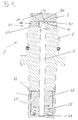
- FIG. 1 shows a cross section of a high-pressure control valve 1 according to the invention.
- the high-pressure control valve 1 has a substantially cylindrical valve body 2, which has an axially extending inlet 20 and a radially extending outlet 21.
- the outlet 21 is presently formed by radially guided bores 23.
- a disc-shaped valve seat 3 is arranged on the valve body 2, which connects the inlet 20 and the outlet 21 via a valve bore 30.
- the valve seat 3 is held on the valve body 2 via a pressure and is braced during installation of the valve 1 in the direction of the valve body 2.
- valve bore 30 can be closed by a sealing element 4 designed as a sealing ball.
- the sealing ball 4 can be pressed against the valve seat 3 for closing the valve bore 30 via an actuating element 5 which is shaped as an actuating pin and which is mounted in an axially extending bore of the valve body 2.
- the valve pin 5 is axially displaceable via an actuating arrangement 6, which is designed in the present case as an electromagnet.
- the electromagnet 6 is essentially constructed from a coil 61 arranged circumferentially to the valve body 2 and on a coil support 60, as well as an armature 62 axially displaceably mounted inside the coil 61 and connected to the valve body 2 via a housing 63.
- a movement of the armature 62 in the axial direction is transmitted via the valve pin 5 to the sealing ball 4, so that opening and closing of the high-pressure control valve 1 is made possible.
- the armature 62 is additionally mounted in a sleeve 65 and biased in the direction of the valve pin 5 by means of a compression spring 68.
- the high pressure control valve 1 is in the de-energized state of the coil 61 to a pressure which is determined by the spring force of the compression spring 68, closed. For pressures beyond this, additional energization of the coil 61 is necessary in order to keep the high-pressure control valve 1 closed against a pressure present at the inlet 20.
- An energization of the coil 61 can take place via laterally outwardly guided connection contacts 64.
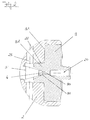
- FIG. 2 shows an enlargement of the valve seat of the high-pressure control valve FIG. 1 ,
- valve seat 3 is extended starting from a base surface 31 of the valve seat in the direction of the radially extending bore 23 of the outlet 21.
- This extension 32 is formed as a circumferential collar-shaped extension 32 which widens in a funnel shape starting from the valve bore 30.
- the extension 32 is guided approximately up to the radially extending bore 23, so that approximately 9/10 of the shoulder 22 formed between the radially extending bore 23 and the base of the valve seat 31 are covered by the extension 32. In this way, it is achieved that a liquid which is present at high pressure on the inlet side and flows past the sealing ball 4 when the valve is opened at a very high flow velocity is not directed directly onto the shoulder 22. In this way, erosion of the valve body 2 in this area is avoided.
- the sealing ball 4 can be pressed via the valve pin 5 against a receptacle 36, which is arranged at the outlet end of the valve bore 30.
- a receptacle 36 which is arranged at the outlet end of the valve bore 30.
Landscapes
- Engineering & Computer Science (AREA)
- General Engineering & Computer Science (AREA)
- Mechanical Engineering (AREA)
- Chemical & Material Sciences (AREA)
- Combustion & Propulsion (AREA)
- Physics & Mathematics (AREA)
- Electromagnetism (AREA)
- Control Of Fluid Pressure (AREA)
- Magnetically Actuated Valves (AREA)
Abstract
Description
- Die vorliegende Erfindung betrifft ein Hochdruckregelventil gemäß dem Oberbegriff des Patentanspruchs 1.
- Derartige Hochdruckregelventile sind aus dem Stand der Technik bspw. zur Druckregelung in Common-Rail Motoren bekannt.
- Die Hochdruckregelung von Flüssigkeiten erfolgt im Allgemeinen über Kugelsitzventile. Diese sind in der Regel elektromagnetisch angesteuert. Elektromagnetisch betriebene Hochdruckregelventile aus dem Stand der Technik sind im Allgemeinen wie folgt aufgebaut, ein Beispiel ist in
Figur 3 dargestellt. - Das Ventil 1 weist einen Ventilkörper 2 mit einem Einlass 20 und einem Auslass 21 auf, wobei einlassseitig, bspw. im Anwendungsbereich der Common-Rail Motoren, derzeit Drücke bis zu 2400 bar anstehen. Zwischen dem Einlass 20 und dem Auslass 21 ist ein Ventilsitz 3 angeordnet, durch den eine Ventilbohrung 30, die Einlass 20 und Auslass 21 verbindet, geführt ist. Die Ventilbohrung 30 ist auslassseitig durch ein Dichtmittel 4, das in der Regel als Dichtkugel ausgeführt ist, abdichtbar. Die Dichtkugel 4 ist dazu über einen Ventilstift 5 gegen den Ventilsitz 3 pressbar. Der Ventilsitz 3 ist aufgrund der erhöhten Belastungen, die durch die Dichtkugel 4 einwirken, aus gehärtetem Stahl gefertigt. Aus Kostengründen ist der restliche Ventilkörper 2 aus ungehärtetem Material gefertigt.
- Der Ventilsitz 3 ist an dem Ventilkörper 2 so angeordnet, dass er die Einlassseite und die Auslassseite verbindet. Der Ventilsitz 3 ist auslassseitig im Wesentlichen plattenförmig ausgestaltet und weist im Bereich der Ventilbohrung 30 eine Vertiefung auf, in der die Dichtkugel 4 zu Liegen kommt. Er ist einlassseitig in den Ventilkörper 2 eingepresst.
- Der Auslass 21 ist durch radiale Bohrungen 23 auf der Auslassseite des Ventilkörpers 2 gebildet. Um eine möglichst kompakte Bauform des Hochdruckreglerventils 1 zu erreichen sind die radialen Bohrungen möglichst knapp unterhalb des Ventilsitzes 3 angeordnet. Durch diese Bauart ist zwischen dem Ventilsitz 3 und den Auslassbohrungen 23 ein Absatz 22 gebildet, an dem sich der Ventilsitz 3 bei der Verschraubung des Ventils abstützt.
- Der Ventilstift 5 ist in einer Längsbohrung des Ventilkörpers 2 gelagert und über eine auslassseitig angeordnete elektromagnetische Antriebseinheit 6 entlang seiner Längsachse bewegbar. Die Antriebseinheit 6 ist vorliegend nicht dargestellt. Sie ist in der Regel aus einer auf einem Spulenträger 60 angeordneten bestrombaren Spule 61 und einem durch ein erzeugtes Magnetfeld betätigbaren Anker 62 aufgebaut. Der Anker 62 und der Ventilstift 5 sind miteinander verschweißt oder verpresst und so feststehend verbunden. Der Anker 62 ist außerdem in Schließrichtung des Ventils mittels einer Druckfeder 68 vorgespannt, sodass das Ventil in unbestromtem Zustand der Spule 61 geschlossen ist.
- Der Anker 62 und die Druckfeder 68 sind rückseitig in einer Buchse 65, die an dem Ventilkörper bspw. über einen Schweißring 66 befestigt ist, gelagert. Der Ventilstift 5 ist in der Buchse 65 über ein Lager 69 zentriert gehalten.
- Die Regelung des Fluiddurchflusses erfolgt durch abheben der Dichtkugel 4 von dem Ventilsitz 3. In aktuellen Hochdruckregelventilen 1 beträgt der maximale Hub, d.h. der Hub, der bei maximaler Öffnung des Ventils erreicht wird, 0,2 - 0,5 mm. Beim Öffnen des Ventils, werden aufgrund des von der Einlassseite auf die Dichtkugel 4 wirkenden Druckes sehr hohe Strömungsgeschwindigkeiten der geregelten Flüssigkeit erreicht. Die Flüssigkeit prallt dann mit dieser hohen Strömungsgeschwindigkeit auf den auslassseitigen Absatz 22 des Ventilkörpers 2 und erodiert diesen, d.h. trägt im Verlauf der Lebensdauer des Ventils zunehmend mehr Material des Absatzes 22 ab, sodass dieser in seiner Materialstärke geschwächt wird.
- Eine Schwächung des Ventilkörpers 2 in diesem Bereich bedeutet gravierende Nachteile hinsichtlich der Lebensdauer des Ventils, da mit zunehmender Erosion weniger Kräfte aus der Verschraubung über den Ventilsitz 3 auf den Ventilkörper 2 übertragen werden können, sodass das Ventil schlussendlich im Bereich der Pressung undicht wird.
- Ein weiterer Nachteil der Erosion ist in dem erfolgenden Materialabtrag zu sehen. Partikel des abgetragenen Materials können in das Kraftstoffsystem gelangen und so bspw. zur Beschädigung der Hochdruckpumpe des Kraftstoffsystems führen.
- Es ist die Aufgabe der vorliegenden Erfindung, bekannte Hochdruckregelventile derart weiterzubilden, dass eine Verwendung bei höheren Drücken von derzeit 2700 - 3000 bar unter gleichzeitiger Verringerung der Materialerosion möglich ist.
- Diese Aufgabe wird gelöst durch ein Hochdruckregelventil mit den Merkmalen des Patentanspruchs 1. Vorteilhafte Weiterbildungen sind Gegenstand von Unteransprüchen.
- Ein erfindungsgemäßes Hochdruckregelventil weist einen Ventilkörper mit einem Einlass und einem Auslass auf, wobei der Auslass durch wenigstens eine im Wesentlichen radial verlaufende Öffnung in dem Ventilkörper gebildet ist. Ein im Wesentlichen scheibenförmig ausgebildeter Ventilsitz ist an dem Ventilkörper zwischen Einlass und Auslass angeordnet und weist eine Ventilbohrung auf, die den Einlass und den Auslass miteinander verbindet. Es ist außerdem ein Dichtelement vorgesehen, das an einem Betätigungselement geeignet zum dichtenden Verschließen der Ventilbohrung angeordnet ist. Das Betätigungselement ist außerdem über eine Betätigungseinrichtung derart bewegbar, dass ein Öffnen und Schließen des Ventils bewirkbar ist. Erfindungsgemäß ist der Ventilsitz derart ausgestaltet, dass der auslassseitig einen sich von einer Grundfläche des Ventilsitzes axial in Richtung der Öffnung erstreckenden umlaufenden Fortsatz aufweist.
- Auf diese Weise wird erreicht, dass ein einlassseitig mit hohem Druck anstehendes Fluid, das beim Öffnen des Ventils durch den beim Öffnungsvorgang im ersten Moment sehr geringer Strömungsquerschnitt mit hoher Geschwindigkeit strömt, entlang des Fortsatzes geleitet wird und damit nicht mit voller Geschwindigkeit auf den sich seitlich erstreckenden Ventilkörper auftrifft. Da der Ventilsitz und damit auch der an dem Ventilsitz angeformte Fortsatz aus gehärtetem Material besteht wird erreicht, dass eine bislang stattfindende Erosion des Ventilkörpers signifikant reduziert wird.
- Eine strömungstechnisch besonders günstige Ausgestaltung des Fortsatzes wird erreicht, wenn dieser als sich trichterförmig erweisender Kragen ausgebildet ist. Auf diese Weise können Strömungsturbulenzen reduziert werden. Abhängig davon, mit welchem Winkel sich der trichterförmige Kragen erweitert, kann außerdem eine hubabhängige Kennlinie des Strömungsquerschnitts gestaltet werden.
- Wenn der Fortsatz wenigstens die Hälfte der Erstreckung zwischen der Grundfläche und der Öffnung abdeckt, kann bereits eine signifikante Reduzierung der Erosion des Ventilkörpers im Bereich der Austrittsöffnung erreicht werden.
- Vorteilhaft ist es, wenn der Fortsatz wenigstens 9/10 der Erstreckung zwischen der Grundfläche und der Öffnung abdeckt, wobei idea-lerweise die komplette Erstreckung zwischen der Grundfläche und der Öffnung von dem Fortsatz abgedeckt ist.
- Auf diese Weise wird erreicht, dass insbesondere ein zwischen der Grundfläche des Ventilsitzes und der Austrittsöffnung liegender Absatz von Materialerosion einer damit einhergehenden Schwächung des dort befindlichen Materials verschon wird. Das ist insbesondere daher wichtig, da der zwischen dem Ventilsitz und der Austrittsöffnung liegende Absatz den Ventilsitz, der in den Ventilkörper eingepresst ist, abstützt.
- Der Fortsatz kann des Weiteren derart ausgestaltet sein, dass beim Öffnen des Ventils ein direktes Anströmen des Ventilkörpers vollständig vermieden wird.
- Es wird auf diese Weise erreicht, dass auch in anderen Bereichen des Ventilkörpers kein Materialabtrag stattfindet und so das Eindringen von Partikeln in den Treibstoffkreislauf vermieden wird.
- Der Fortsatz kann außerdem eine an das Dichtelement angepasste Ausnehmung aufweisen, so dass eine optimierte Anlagefläche zur Abdichtung zwischen dem Ventilsitz und dem Dichtelement gebildet wird.
- Das Dichtelement ist bevorzugt als Dichtkugel ausgebildet. Das hat den Vorteil, dass durch die rotationssymmetrische Ausgestaltung einer Kugel eine besonders gute Abdichtung in Bezug auf eine Bohrung erfolgen kann.
- Eine Betätigung des Dichtelements kann besonders einfach erfolgen, wenn das Betätigungselement als Betätigungsstift ausgebildet ist. Eine stiftförmige Ausgestaltung des Betätigungselements hat den Vorteil, dass dieses auf diese Weise besonders einfach durch den Ventilkörper in Richtung der Betätigungseinrichtung, die beispielsweise als Elektromagnet ausgeführt ist, geführt werden kann.
- Es ist strömungstechnisch besonders vorteilhaft, wenn ein Strömungsquerschnitt zwischen dem Betätigungselement und dem Fortsatz derart ausgestaltet ist, dass Verwirbelung in der Strömung reduziert werden. Auf diese Weise wird ein besonders regelmäßiger Fluidfluss erreicht und es werden durch Verwirbelungen in den Fluidkreislauf induzierte Kräfte reduziert.
- Die Erfindung wird nachfolgend ausführlich unter Bezugnahme auf die beigefügten Figuren erläutert. Es zeigen:
- Figur 1
- ein erfindungsgemäßes Hochdruckregelventil im Querschnitt,
- Figur 2
- den Ventilsitz des Hochdruckregelventils aus
Figur 1 in vergrößerter Darstellung und - Figur 3
- ein Hochdruckregelventil gemäß dem Stand der Technik (schon behandelt).
-
Figur 1 zeigt einen Querschnitt eines erfindungsgemäßen Hochdruckregelventils 1. Das Hochdruckregelventil 1 weist einen im Wesentlichen zylinderförmig ausgestalteten Ventilkörper 2 auf, der einen axial verlaufenden Einlass 20 sowie einen radial verlaufenden Auslass 21 aufweist. Der Auslass 21 ist vorliegend durch radial geführte Bohrungen 23 gebildet. Einlassseitig ist an dem Ventilkörper 2 ein scheibenförmiger Ventilsitz 3 angeordnet, der über eine Ventilbohrung 30 den Einlass 20 und den Auslass 21 verbindet. Der Ventilsitz 3 ist an dem Ventilkörper 2 über eine Pressung gehaltert und wird beim Einbau des Ventils 1 in Richtung des Ventilkörpers 2 verspannt. - Auslassseitig ist die Ventilbohrung 30 durch ein als Dichtkugel ausgestaltetes Dichtelement 4 verschließbar. Die Dichtkugel 4 ist zum Verschließen der Ventilbohrung 30 über ein als Betätigungsstift ausgeformtes Betätigungselement 5, das in einer axial verlaufenden Bohrung des Ventilkörpers 2 gelagert ist, gegen den Ventilsitz 3 pressbar. Der Ventilstift 5 ist über eine Betätigungsanordnung 6, die im vorliegenden Fall als Elektromagnet ausgebildet ist, axial verschiebbar. Der Elektromagnet 6 ist im Wesentlichen aus einer umfänglich zu dem Ventilkörper 2 und auf einem Spulenträger 60 angeordneten Spule 61 sowie einen im Inneren der Spule 61 axial verschiebbar gelagerten Anker 62 aufgebaut und über ein Gehäuse 63 mit dem Ventilkörper 2 verbunden. Eine Bewegung des Ankers 62 in Axialrichtung wird über den Ventilstift 5 auf die Dichtkugel 4 übertragen, so dass ein Öffnen und Schließen des Hochdruckregelventils 1 ermöglicht wird. Der Anker 62 ist zusätzlich in einer Buchse 65 gelagert und in Richtung des Ventilstifts 5 mittels einer Druckfeder 68 vorgespannt. Das Hochdruckregelventil 1 ist dadurch in unbestromten Zustand der Spule 61 bis zu einem Druck, der durch die Federkraft der Druckfeder 68 bestimmt ist, geschlossen. Bei darüber hinausgehenden Drücken ist eine zusätzliche Bestromung der Spule 61 notwendig, um das Hochdruckregelventil 1 gegen einen am Einlass 20 anstehenden Druck geschlossen zu halten.
- Eine Bestromung der Spule 61 kann über seitlich nach außen geführte Anschlusskontakte 64 erfolgen.
-
Figur 2 zeigt eine Vergrößerung des Ventilsitzes des Hochdruckregelventils ausFigur 1 . - In dieser Darstellung ist deutlich zu erkennen, dass der Ventilsitz 3 ausgehend von einer Grundfläche 31 des Ventilsitzes in Richtung der radial verlaufenden Bohrung 23 des Auslasses 21 verlängert ist. Dieser Fortsatz 32 ist als umlaufender kragenförmiger Fortsatz 32 ausgebildet, der sich ausgehend von der Ventilbohrung 30 trichterförmig erweitert. Der Fortsatz 32 ist annähernd bis zur radial verlaufenden Bohrung 23 geführt, so dass in etwa 9/10 des zwischen der radial verlaufenden Bohrung 23 und der Grundfläche des Ventilsitzes 31 gebildeten Absatzes 22 von dem Fortsatz 32 abgedeckt sind. Auf diese Weise wird erreicht, dass eine Flüssigkeit, die einlassseitig mit hohem Druck ansteht und beim Öffnen des Ventils mit sehr hoher Strömungsgeschwindigkeit an der Dichtkugel 4 vorbeiströmt nicht direkt auf den Absatz 22 gelenkt wird. Auf diese Weise wird eine Erosion des Ventilkörpers 2 in diesem Bereich vermieden. Die Dichtkugel 4 ist über den Ventilstift 5 gegen eine Aufnahme 36, die am auslassseitigen Ende der Ventilbohrung 30 angeordnet ist, pressbar. Durch eine an die Ventilkugel 4 angepasste Aufnahme 36 ist ein besseres Dichtverhalten des Ventilsitzes 3 erreichbar.
- Durch eine trichterförmige Aufweiterung des Fortsatzes 32, ausgehend vom auslassseitigen Ende der Ventilbohrung 30 kann eine hubabhängige Kennlinie des freigegebenen Strömungsquerschnittes erreicht werden, so dass eine optimierte Durchfluss-und Druckregelung erreicht werden kann.
- Durch eine entsprechende Ausgestaltung der trichterförmigen Aufweitung des Fortsatzes 32 kann außerdem eine Reduktion von Strömungsturbulenzen auf der Ausgangsseite des Hochdruckregelventils 1 erreicht werden.
-
- 1
- Hochdruckregelventil
- 2
- Ventilkörper
- 3
- Ventilsitz
- 4
- Dichtelement
- 5
- Betätigungselement
- 6
- Betätigungseinrichtung
- 20
- Einlass
- 21
- Auslass
- 22
- Absatz/Erstreckung
- 23
- Öffnung/Bohrung
- 30
- Ventilbohrung
- 31
- Grundfläche
- 32
- Fortsatz
- 36
- Aufnahme
- 60
- Spulenträger
- 61
- Spule
- 62
- Anker
- 63
- Gehäuse
- 64
- Anschlusskontakte
- 65
- Buchse
- 66
- Schweißung
- 68
- Druckfeder
- 69
- Lagerung
Claims (10)
- Hochdruckregelventil (1) mit
einem Ventilkörper (2) mit einem Einlass 20 und einem Auslass (21), wobei der Auslass (21) durch wenigstens eine radial verlaufende Öffnung (23) in dem Ventilkörper (2) gebildet ist, einem im wesentlichen scheibenförmig ausgebildeten Ventilsitz (3), der an dem Ventilkörper (2) zwischen dem Einlass (20) und dem Auslass (21) angeordnet ist und eine Ventilbohrung (30) aufweist, die Einlass (20) und Auslass (21) verbindet,
einem Dichtelement (4), das an einem Betätigungselement (5) geeignet angeordnet ist, die Ventilbohrung 30 zu verschließen und
einer Betätigungseinrichtung (6), die geeignet ausgebildet ist, das Betätigungselement (5) derart zu bewegen, dass ein Öffnen und Schließen des Ventils bewirkt wird,
dadurch gekennzeichnet, dass
der Ventilsitz (3) auslassseitig einen sich von einer Grundfläche (31) axial in Richtung der Öffnung (23) erstreckenden umlaufenden Fortsatz (32) aufweist. - Hochdruckregelventil (1) nach Anspruch 1,
dadurch gekennzeichnet, dass
der Fortsatz (32) als sich trichterförmig erweiternder Kragen ausgebildet ist. - Hochdruckregelventil (1) nach Anspruch 1 oder 2,
dadurch gekennzeichnet, dass
der Fortsatz (32) wenigstens die Hälfte der Erstreckung (22) zwischen der Grundfläche (31) und der Öffnung (23) abdeckt. - Hochdruckregelventil (1) nach Anspruch 3,
dadurch gekennzeichnet, dass
der Fortsatz (32) wenigstens 9/10 der Erstreckung (22) zwischen der Grundfläche und der Öffnung abdeckt. - Hochdruckregelventil (1) nach Anspruch 4,
dadurch gekennzeichnet, dass
der Fortsatz (32) die komplette Erstreckung zwischen der Grundfläche (31) und der Öffnung (23) abdeckt. - Hochdruckregelventil (1) nach einem der vorhergehenden Ansprüche,
dadurch gekennzeichnet, dass
der Fortsatz (32) derart ausgebildet ist, dass beim Öffnen des Ventils (1) ein direktes Anströmen des Ventilkörpers (2) vermieden wird. - Hochdruckregelventil (1) nach einem der vorhergehenden Ansprüche,
dadurch gekennzeichnet, dass
der Fortsatz (32) eine Ausnehmung (36) zur Aufnahme des Dichtelements (4) aufweist. - Hochdruckregelventil (1) nach einem der vorhergehenden Ansprüche,
dadurch gekennzeichnet, dass
das Dichtelement (4) als Dichtkugel ausgebildet ist. - Hochdruckregelventil (1) nach einem der vorhergehenden Ansprüche,
dadurch gekennzeichnet, dass
das Betätigungselement (5) als Betätigungsstift ausgebildet ist. - Hochdruckregelventil (1) nach einem der vorhergehenden Ansprüche,
dadurch gekennzeichnet, dass
ein Strömungsquerschnitt zwischen dem Dichtelement (4) und dem Fortsatz (32) derart ausgestaltet ist, dass Verwirbelungen in der Strömung reduziert werden.
Priority Applications (1)
| Application Number | Priority Date | Filing Date | Title |
|---|---|---|---|
| EP11186025.0A EP2444652A3 (de) | 2010-10-21 | 2011-10-20 | Hochdruckregelventil |
Applications Claiming Priority (2)
| Application Number | Priority Date | Filing Date | Title |
|---|---|---|---|
| DE102010049035A DE102010049035A1 (de) | 2010-10-21 | 2010-10-21 | Hochdruckregelventil |
| EP11186025.0A EP2444652A3 (de) | 2010-10-21 | 2011-10-20 | Hochdruckregelventil |
Publications (2)
| Publication Number | Publication Date |
|---|---|
| EP2444652A2 true EP2444652A2 (de) | 2012-04-25 |
| EP2444652A3 EP2444652A3 (de) | 2013-07-24 |
Family
ID=48579640
Family Applications (1)
| Application Number | Title | Priority Date | Filing Date |
|---|---|---|---|
| EP11186025.0A Withdrawn EP2444652A3 (de) | 2010-10-21 | 2011-10-20 | Hochdruckregelventil |
Country Status (1)
| Country | Link |
|---|---|
| EP (1) | EP2444652A3 (de) |
Cited By (4)
| Publication number | Priority date | Publication date | Assignee | Title |
|---|---|---|---|---|
| WO2013172764A1 (en) * | 2012-05-16 | 2013-11-21 | Scania Cv Ab | Vavle for a fuel system for a combustion engine and method for controlling a fuel system for a combustion engine |
| WO2014095595A1 (fr) * | 2012-12-18 | 2014-06-26 | Delphi International Operations Luxembourg S.À.R.L. | Buse, vanne haute pression apte a recevoir la buse et rampe commune apte a recevoir la buse |
| WO2015055512A1 (de) * | 2013-10-15 | 2015-04-23 | Continental Automotive Gmbh | Ventil |
| EP2905669A3 (de) * | 2014-02-11 | 2015-12-30 | Kendrion (Villingen) GmbH | Druckregelventil |
Family Cites Families (4)
| Publication number | Priority date | Publication date | Assignee | Title |
|---|---|---|---|---|
| DE19700980A1 (de) * | 1997-01-14 | 1998-07-16 | Teves Gmbh Alfred | Elektromagnetventil |
| JP4193823B2 (ja) * | 2005-07-29 | 2008-12-10 | 株式会社デンソー | バルブ装置 |
| US7441546B2 (en) * | 2005-07-28 | 2008-10-28 | Denso Corporation | Valve apparatus |
| JP2009103050A (ja) * | 2007-10-23 | 2009-05-14 | Denso Corp | 電磁駆動装置 |
-
2011
- 2011-10-20 EP EP11186025.0A patent/EP2444652A3/de not_active Withdrawn
Non-Patent Citations (1)
| Title |
|---|
| None |
Cited By (15)
| Publication number | Priority date | Publication date | Assignee | Title |
|---|---|---|---|---|
| EP2850311A4 (de) * | 2012-05-16 | 2016-01-13 | Scania Cv Ab | Ventil für ein kraftstoffsystem eines verbrennungsmotors und verfahren zur steuerung eines kraftstoffsystems eines verbrennungsmotors |
| US9964089B2 (en) | 2012-05-16 | 2018-05-08 | Scania Cv Ab | Valve for a fuel system for a combustion engine and method for controlling a fuel system for a combustion engine |
| CN104285057A (zh) * | 2012-05-16 | 2015-01-14 | 斯堪尼亚商用车有限公司 | 用于燃烧发动机的燃料系统的阀和控制燃烧发动机的燃料系统的方法 |
| KR20150006885A (ko) * | 2012-05-16 | 2015-01-19 | 스카니아 씨브이 악티에볼라그 | 연소 엔진용 연료 시스템을 위한 밸브 및 연소 엔진용 연료 시스템을 제어하기 위한 방법 |
| CN104285057B (zh) * | 2012-05-16 | 2017-07-18 | 斯堪尼亚商用车有限公司 | 用于燃烧发动机的燃料系统的阀和控制燃烧发动机的燃料系统的方法 |
| WO2013172764A1 (en) * | 2012-05-16 | 2013-11-21 | Scania Cv Ab | Vavle for a fuel system for a combustion engine and method for controlling a fuel system for a combustion engine |
| KR101626535B1 (ko) | 2012-05-16 | 2016-06-13 | 스카니아 씨브이 악티에볼라그 | 연소 엔진용 연료 시스템을 위한 밸브 및 연소 엔진용 연료 시스템을 제어하기 위한 방법 |
| KR101709105B1 (ko) | 2012-12-18 | 2017-02-22 | 델피 인터내셔널 오퍼레이션즈 룩셈부르크 에스.에이 알.엘. | 노즐, 노즐을 수용할 수 있는 고압 밸브, 및 노즐을 수용할 수 있는 커먼 레일 |
| KR20150082630A (ko) * | 2012-12-18 | 2015-07-15 | 델피 인터내셔널 오퍼레이션즈 룩셈부르크 에스.에이 알.엘. | 노즐, 노즐을 수용할 수 있는 고압 밸브, 및 노즐을 수용할 수 있는 커먼 레일 |
| US9677524B2 (en) | 2012-12-18 | 2017-06-13 | Delphi International Operations Luxembourg S.A.R.L. | High pressure valve |
| WO2014095595A1 (fr) * | 2012-12-18 | 2014-06-26 | Delphi International Operations Luxembourg S.À.R.L. | Buse, vanne haute pression apte a recevoir la buse et rampe commune apte a recevoir la buse |
| EP3404250A1 (de) * | 2012-12-18 | 2018-11-21 | Delphi International Operations Luxembourg S.à r.l. | Hochdruckventil |
| WO2015055512A1 (de) * | 2013-10-15 | 2015-04-23 | Continental Automotive Gmbh | Ventil |
| US9803602B2 (en) | 2013-10-15 | 2017-10-31 | Continental Automotive Gmbh | Valve |
| EP2905669A3 (de) * | 2014-02-11 | 2015-12-30 | Kendrion (Villingen) GmbH | Druckregelventil |
Also Published As
| Publication number | Publication date |
|---|---|
| EP2444652A3 (de) | 2013-07-24 |
Similar Documents
| Publication | Publication Date | Title |
|---|---|---|
| EP2630360B1 (de) | Hochdruckregelventil | |
| EP2102486B1 (de) | Injektor mit axial-druckausgeglichenem steuerventil | |
| EP3161299B1 (de) | Gasventil | |
| EP3102863B1 (de) | Elektromagnetventil sowie verbrennungsmotorkühlsystem mit elektromagnetventil | |
| DE102015005977A1 (de) | Entnahmeventil | |
| EP2444652A2 (de) | Hochdruckregelventil | |
| EP4150201B1 (de) | Gasdosierventil für brennkraftmaschinen | |
| WO2011095367A1 (de) | Steuerventilanordnung eines kraftstoffinjektors | |
| EP2757246A2 (de) | Hochdruckventil | |
| EP2444653A2 (de) | Hochdruckregelventil | |
| EP3353408B1 (de) | Elektrischer aktor einer ventileinrichtung | |
| EP2021616B1 (de) | Magnetventil mit geflutetem ankerraum | |
| EP2314860B1 (de) | Kraftstoff-Injektor | |
| WO2016034402A1 (de) | Elektromagnetisch betätigbares proportionalventil | |
| WO2017080861A1 (de) | Elektromagnetischer aktor für eine ventileinrichtung | |
| EP3420257B1 (de) | Magnetventil | |
| WO2018028865A1 (de) | Elektromagnetisch betätigbares saugventil und kraftstoff-hochdruckpumpe | |
| DE102006003484A1 (de) | Vorrichtung zum Einspritzen von Kraftstoff | |
| EP3032090B1 (de) | Schalt- oder druckregelventil für ein kraftstoffeinspritzsystem | |
| EP2596228B1 (de) | Steuerventil | |
| WO2019161878A1 (de) | Ventilvorrichtung für ein druckfluidsystem | |
| DE112018002148T5 (de) | Hochdruckkraftstoffversorgungspumpe | |
| EP3423717B1 (de) | Elektromagnetisch betätigbares einlassventil und hochdruckpumpe mit einlassventil | |
| WO2009080414A1 (de) | Injektor eines kraftstoffeinspritzsystems mit einem 3/2-wege-steuerventil | |
| EP2880297B1 (de) | Hochdruckpumpe für brennkraftmaschinen |
Legal Events
| Date | Code | Title | Description |
|---|---|---|---|
| AK | Designated contracting states |
Kind code of ref document: A2 Designated state(s): AL AT BE BG CH CY CZ DE DK EE ES FI FR GB GR HR HU IE IS IT LI LT LU LV MC MK MT NL NO PL PT RO RS SE SI SK SM TR |
|
| AX | Request for extension of the european patent |
Extension state: BA ME |
|
| PUAI | Public reference made under article 153(3) epc to a published international application that has entered the european phase |
Free format text: ORIGINAL CODE: 0009012 |
|
| PUAL | Search report despatched |
Free format text: ORIGINAL CODE: 0009013 |
|
| AK | Designated contracting states |
Kind code of ref document: A3 Designated state(s): AL AT BE BG CH CY CZ DE DK EE ES FI FR GB GR HR HU IE IS IT LI LT LU LV MC MK MT NL NO PL PT RO RS SE SI SK SM TR |
|
| AX | Request for extension of the european patent |
Extension state: BA ME |
|
| RIC1 | Information provided on ipc code assigned before grant |
Ipc: F02M 63/00 20060101AFI20130620BHEP Ipc: F16K 31/06 20060101ALI20130620BHEP |
|
| STAA | Information on the status of an ep patent application or granted ep patent |
Free format text: STATUS: THE APPLICATION IS DEEMED TO BE WITHDRAWN |
|
| 18D | Application deemed to be withdrawn |
Effective date: 20140125 |