EP1336738A2 - Einrichtung zum Einbringen von Kraftstoff zur Verbrennung in einer Brennkraftmaschine - Google Patents
Einrichtung zum Einbringen von Kraftstoff zur Verbrennung in einer Brennkraftmaschine Download PDFInfo
- Publication number
- EP1336738A2 EP1336738A2 EP03000716A EP03000716A EP1336738A2 EP 1336738 A2 EP1336738 A2 EP 1336738A2 EP 03000716 A EP03000716 A EP 03000716A EP 03000716 A EP03000716 A EP 03000716A EP 1336738 A2 EP1336738 A2 EP 1336738A2
- Authority
- EP
- European Patent Office
- Prior art keywords
- fuel
- functional area
- valve
- flow
- internal combustion
- Prior art date
- Legal status (The legal status is an assumption and is not a legal conclusion. Google has not performed a legal analysis and makes no representation as to the accuracy of the status listed.)
- Granted
Links
Images

Classifications
-
- F—MECHANICAL ENGINEERING; LIGHTING; HEATING; WEAPONS; BLASTING
- F02—COMBUSTION ENGINES; HOT-GAS OR COMBUSTION-PRODUCT ENGINE PLANTS
- F02M—SUPPLYING COMBUSTION ENGINES IN GENERAL WITH COMBUSTIBLE MIXTURES OR CONSTITUENTS THEREOF
- F02M21/00—Apparatus for supplying engines with non-liquid fuels, e.g. gaseous fuels stored in liquid form
- F02M21/02—Apparatus for supplying engines with non-liquid fuels, e.g. gaseous fuels stored in liquid form for gaseous fuels
- F02M21/0218—Details on the gaseous fuel supply system, e.g. tanks, valves, pipes, pumps, rails, injectors or mixers
- F02M21/023—Valves; Pressure or flow regulators in the fuel supply or return system
- F02M21/0239—Pressure or flow regulators therefor
-
- F—MECHANICAL ENGINEERING; LIGHTING; HEATING; WEAPONS; BLASTING
- F02—COMBUSTION ENGINES; HOT-GAS OR COMBUSTION-PRODUCT ENGINE PLANTS
- F02B—INTERNAL-COMBUSTION PISTON ENGINES; COMBUSTION ENGINES IN GENERAL
- F02B43/00—Engines characterised by operating on gaseous fuels; Plants including such engines
- F02B43/10—Engines or plants characterised by use of other specific gases, e.g. acetylene, oxyhydrogen
-
- F—MECHANICAL ENGINEERING; LIGHTING; HEATING; WEAPONS; BLASTING
- F02—COMBUSTION ENGINES; HOT-GAS OR COMBUSTION-PRODUCT ENGINE PLANTS
- F02D—CONTROLLING COMBUSTION ENGINES
- F02D19/00—Controlling engines characterised by their use of non-liquid fuels, pluralities of fuels, or non-fuel substances added to the combustible mixtures
- F02D19/02—Controlling engines characterised by their use of non-liquid fuels, pluralities of fuels, or non-fuel substances added to the combustible mixtures peculiar to engines working with gaseous fuels
- F02D19/021—Control of components of the fuel supply system
- F02D19/023—Control of components of the fuel supply system to adjust the fuel mass or volume flow
-
- F—MECHANICAL ENGINEERING; LIGHTING; HEATING; WEAPONS; BLASTING
- F02—COMBUSTION ENGINES; HOT-GAS OR COMBUSTION-PRODUCT ENGINE PLANTS
- F02M—SUPPLYING COMBUSTION ENGINES IN GENERAL WITH COMBUSTIBLE MIXTURES OR CONSTITUENTS THEREOF
- F02M21/00—Apparatus for supplying engines with non-liquid fuels, e.g. gaseous fuels stored in liquid form
- F02M21/02—Apparatus for supplying engines with non-liquid fuels, e.g. gaseous fuels stored in liquid form for gaseous fuels
- F02M21/0218—Details on the gaseous fuel supply system, e.g. tanks, valves, pipes, pumps, rails, injectors or mixers
- F02M21/023—Valves; Pressure or flow regulators in the fuel supply or return system
- F02M21/0233—Details of actuators therefor
-
- F—MECHANICAL ENGINEERING; LIGHTING; HEATING; WEAPONS; BLASTING
- F02—COMBUSTION ENGINES; HOT-GAS OR COMBUSTION-PRODUCT ENGINE PLANTS
- F02M—SUPPLYING COMBUSTION ENGINES IN GENERAL WITH COMBUSTIBLE MIXTURES OR CONSTITUENTS THEREOF
- F02M21/00—Apparatus for supplying engines with non-liquid fuels, e.g. gaseous fuels stored in liquid form
- F02M21/02—Apparatus for supplying engines with non-liquid fuels, e.g. gaseous fuels stored in liquid form for gaseous fuels
- F02M21/0203—Apparatus for supplying engines with non-liquid fuels, e.g. gaseous fuels stored in liquid form for gaseous fuels characterised by the type of gaseous fuel
- F02M21/0206—Non-hydrocarbon fuels, e.g. hydrogen, ammonia or carbon monoxide
-
- F—MECHANICAL ENGINEERING; LIGHTING; HEATING; WEAPONS; BLASTING
- F02—COMBUSTION ENGINES; HOT-GAS OR COMBUSTION-PRODUCT ENGINE PLANTS
- F02M—SUPPLYING COMBUSTION ENGINES IN GENERAL WITH COMBUSTIBLE MIXTURES OR CONSTITUENTS THEREOF
- F02M21/00—Apparatus for supplying engines with non-liquid fuels, e.g. gaseous fuels stored in liquid form
- F02M21/02—Apparatus for supplying engines with non-liquid fuels, e.g. gaseous fuels stored in liquid form for gaseous fuels
- F02M21/0218—Details on the gaseous fuel supply system, e.g. tanks, valves, pipes, pumps, rails, injectors or mixers
- F02M21/0287—Details on the gaseous fuel supply system, e.g. tanks, valves, pipes, pumps, rails, injectors or mixers characterised by the transition from liquid to gaseous phase ; Injection in liquid phase; Cooling and low temperature storage
-
- Y—GENERAL TAGGING OF NEW TECHNOLOGICAL DEVELOPMENTS; GENERAL TAGGING OF CROSS-SECTIONAL TECHNOLOGIES SPANNING OVER SEVERAL SECTIONS OF THE IPC; TECHNICAL SUBJECTS COVERED BY FORMER USPC CROSS-REFERENCE ART COLLECTIONS [XRACs] AND DIGESTS
- Y02—TECHNOLOGIES OR APPLICATIONS FOR MITIGATION OR ADAPTATION AGAINST CLIMATE CHANGE
- Y02T—CLIMATE CHANGE MITIGATION TECHNOLOGIES RELATED TO TRANSPORTATION
- Y02T10/00—Road transport of goods or passengers
- Y02T10/10—Internal combustion engine [ICE] based vehicles
- Y02T10/30—Use of alternative fuels, e.g. biofuels
Definitions
- the invention relates to a device for the intermittent introduction of Fuel, especially gaseous hydrogen, for combustion in an internal combustion engine.
- valves with a closing body moved linearly or longitudinally to the direction of flow slides, which one cover bodies moving straight across the flow, taps; where a closing body rotates about an axis transverse to Flow is movable and is flowed through in the open position as well
- Flaps which are characterized by the fact that a disc-shaped End body is rotatable about an axis transverse to the flow and is flowed around in the open position.
- DE 43 08 is an example of fuel metering using a lift valve 775 C1, which is a gas injection valve for blowing in Describes hydrogen gas in the combustion chamber of an internal combustion engine.
- the described valve comprises a longitudinally displaceable piston and a this connected poppet valve, which is in the fuel flow direction opens.
- DE 39 04 480 A1 describes the introduction of Using fuel in the intake manifold of an internal combustion engine of a rotary slide valve, which results in a cosine-shaped metering movement results. With the described execution an attempt is made to climb a steep one Rapid increase in or decrease in the amount of fuel injected to drive over the control edges.
- DE 39 04 480 A1 also fulfills the requirements regarding Fuel metering is very inadequate.
- principle-related disadvantages of the rotary valve have been particularly inadequate Tightness and the resulting large and uncontrolled leakage in exposed unactuated condition.
- Shut-off valves are also required to achieve a complete shut-off required.
- the object of the invention is to provide a device for Introduction of fuel for combustion in an internal combustion engine, which, while avoiding the disadvantages mentioned, is a very accurate metering of the fuel, especially with regard to the Mass flow and on the other hand a particularly dynamic metering allowed.
- a first Functional area for positioning, according to a regulation of the Fuel mass flow and a second functional area for switching, provided according to an opening or blocking the fuel flow is; the underlying idea thus includes the functional and / or structural separation of an area by means of which a variable The amount of fuel is measurable on the one hand and an area by means of which the fuel within defined limits with regard to time, course and / or duration can be supplied on the other hand.
- the gaseous fuel is in particular: Hydrogen, however, the device according to the invention can also with other gaseous fuels such as LPG or natural gas be used.
- both the first and the second functional area comprise one controllable actuator.
- the cross section of the flow Fuel path can be varied continuously or discretely, by means of the second The fuel path can be opened or closed in the functional area.
- a movable between two end positions Closure device includes, is by means of the first functional area at least one end position can be shifted in such a way that a change in the Movement range of the closure device takes place; a change of the maximum stroke thus results in a metering of the mass flow.
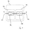
- FIG. 1 shows a functional structure of an injection valve 100 for intermittent introduction of fuel, especially gaseous Hydrogen, for combustion in a not shown here Internal combustion engine; valve 100 is located in the fuel path and has an inlet 110 and an outlet 112. Unnamed the In the present presentation, it is of course just as useful if functional areas 102 and 104 are in reverse order are arranged so that the functional area 104 in front of the fuel flow the functional area 102. It will be particularly advantageous viewed when functional areas 102 and 104 are structurally in a valve 100 are united, however, it may well be useful that Functional areas 102 and 104 to be provided structurally separately.
- each functional area 102 and 104 now has a specific one Task accomplished, which means not just a construction conflicting requirements and the resulting constraint Compromise is avoided, but an optimal one, of each specific constructive design of everyone Functional area 102 and 104 is made possible.
- An actuator is assigned to functional areas 102 and 104, so that an actuator independent control is enabled.
- the functional area 102 comprises a device 106 by means of which it it is possible to measure a variable amount of fuel.
- the device 106 is a slide, expediently with mass-proportional flow cross-section or an orifice, by means of which the flow cross section is changeable.
- the device 106 is also independent of another functional area 104 is used.
- the functional area 104 comprises a device 108 by means of which the Fuel flow is switchable.
- the device 108 is, for example, a Magnetic closing valve, which supplies fuel within defined limits in terms of time, course, and / or duration.
- the device is concerned 108 around a closure unit, which between an open position and movable in a closed position, the device 106 is designed such that by means of it at least one of the stops, which the end positions for the Form movement of the closure unit is displaceable.
- the mass flow is metered by means of, for example actuator-controlled adjustment of at least one stop, one Switching takes place by opening / closing by means of the locking unit of the Facility 108.
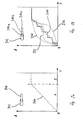
- a characteristic curve 200 with stepless cross-sectional variation is shown in FIG. 2a shown.
- the opening cross section is A for the fuel flow plotted against the travel s of an adjusting device. Is symbolic a possible realization in the form of two depending on the position for example a slider of overlapping openings 202 and 204 shown. In the figure, a linearly increasing in area A is constant in B. characteristic curve shown. According to the shape of the However, openings 202, 204 is an almost arbitrary characteristic (FIG. 2b 220, 222, 224) possible, so that the valve according to the invention to everyone Use case is customizable.
- a characteristic curve 210 with a discrete cross-sectional variation is shown in FIG. 2b. Also here is the opening cross section A for the fuel flow against the Travel s of an adjustment device.
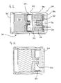
- FIG. 3a shows a structural design of a 2-actuator valve shown.
- the fuel mass flow comprises a first actuator 306, which rotationally a mass flow allocation unit connected to it in a rotationally fixed manner 304 moves.
- Mass flow allocation unit 304 has one or more Perimeter distributed openings, which with openings 302 in the housing 300 of the valve correspond, so that according to the direction of the arrow Fuel flows in perpendicular to the valve axis.
- the Allocation of fuel mass flow according to the position of the first Actuator and thus the degree of overlap of the openings 302 and Openings of the mass flow allocation unit 304.
- the fuel inflow 302 is arranged approximately axially in the center, from where proceeding in the direction of the valve end 305 in a direction of the extends first actuator 306 comprehensive housing region. In the other The direction closes in the direction of the valve end 306 Functional area 303, which the opening or closing of the Allows fuel flow.
- the mass flow allocation unit 304 of the first Functional area 301 is an adjustment of the flow rate in Dependence of a variety of parameters such as pressure, temperature, Allows fuel type, engine load and / or speed, so the Shutter unit 310 can operate in a dynamic range which the time share of the opening and closing processes on Metering process is small. Closure unit 310 also takes over the actual sealing function in the valve.
- Figure 3b shows a structural design of the first Functional area 301 of the valve with discrete cross-sectional variation.
- the Openings of the mass flow allocation unit 320 correspond to this a plurality of openings 322 in the valve body 324.
- the Actuation of the mass flow allocation unit 320 by means of a stepping motor the settling process or the step tolerance in areas becomes constructive in which there is no partial (oscillating) overlap of Openings. In this way, a very exact fuel metering achieved and the regulatory effort minimized.
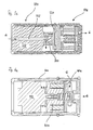
- FIG. 3c A further embodiment with a facing slide valve is shown in FIG. 3c shown.
- the fuel also emerges in the axial direction accordingly the direction of the arrow into the valve, wherein in the first functional area 334 the flows through first actuator 338, which has a channel 332.
- the Mass flow allocation unit 320 acts flat - in the axial direction; a feather 340 ensures sufficient contact pressure. Further follows in the direction of Fuel flow, as already described with Figure 3a, the closure unit of the second functional area 336.
- Figure 4a shows a constructive embodiment of the further embodiment with variable stop.
- a first actuator 402 for actuating a variable stop arranged in the valve housing 400 Functional area for variable fuel mass flow allocation, comprehensive a first actuator 402 for actuating a variable stop arranged.
- the variable stop is due to the axially displaceable position a second actuator 404 is formed, which for actuating a Closure unit 406 can be controlled, the exposed positions of one Correspond to the open or closed position.
- the hub between these two End positions - and thus the cross-section through which they flow - is determined using the Actuator 402 determined by the location of the variable stop.
- This Embodiment enables very good dosing at the same time large spread in mass flow rate and short switching times.
- FIG. 4b A further constructive embodiment of this embodiment variable stop is shown with FIG. 4b, the first actuator 422 the variable stop 424 rotated.
- the closure unit 426 is adjustable in accordance with that by the Stop 424 limited adjustment range. Otherwise it works analogous to the embodiment shown in FIG. 4a.
- FIG. 4c shows an embodiment with an axial mass flow supply.
- the first actuator 440 is provided with an axial passage for fuel.
- m ⁇ also denotes the fuel mass flow with respect to its direction.
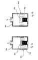
- FIGS. 5a and 5b A basic illustration of the further embodiment is shown in FIGS. 5a and 5b.
- a variable stop 502 is located in a valve housing 500 arranged which in the first end position only a small stroke 506 of Closure body 504 allows and in a second end position maximum stroke 508 of the closure body 504 allowed. If applicable at least the stroke of the closure body 504 in the first end position 506 almost zero.
- the present valve is particularly suitable for use in connection with the fuel hydrogen (H 2 ).
- the valve according to the invention advantageously enables the storage of the hydrogen, for example in the liquid state, at very low temperatures at approximately -250 ° C. in a cryogenic tank with a very low operating pressure, since the valve does not have to be preceded by a pressure reducer and therefore does not require a high pressure drop, which means that the period of time until H 2 loss due to blowing out via the safety valve when heating / increasing pressure in the tank is significantly extended.
Landscapes
- Engineering & Computer Science (AREA)
- Chemical & Material Sciences (AREA)
- Combustion & Propulsion (AREA)
- Mechanical Engineering (AREA)
- General Engineering & Computer Science (AREA)
- Chemical Kinetics & Catalysis (AREA)
- General Chemical & Material Sciences (AREA)
- Oil, Petroleum & Natural Gas (AREA)
- Analytical Chemistry (AREA)
- Output Control And Ontrol Of Special Type Engine (AREA)
Abstract
Description
- Figur 1
- ein Funktionsstruktur eines Einblasventils,
- Figur 2a
- eine Kennlinie bei stufenloser Querschnittsvariierung,
- Figur 2b
- eine Kennlinie bei diskreter Querschnittsvariierung,
- Figur 3a
- eine konstruktive Ausgestaltung eines 2-Aktor-Ventils,
- Figur 3b
- eine konstruktive Ausgestaltung mit diskreter Querschnittsvariierung
- Figur 3c
- eine Ausgestaltung mit Plandrehschieberventil,
- Figur 4a
- eine konstruktive Ausgestaltung mit variablem Anschlag, linear verstellend,
- Figur 4b
- eine konstruktive Ausgestaltung mit variablem Anschlag, rotatorisch verstellend,
- Figur 4c
- eine Ausgestaltung mit axialer Massenstromzufuhr,
- Figur 5a
- eine Prinzipdarstellung einer Ausgestaltung mit variablem Anschlag sowie
- Figur 5b
- eine Prinzipdarstellung einer Ausgestaltung mit variablem Anschlag.
Claims (6)
- Einrichtung zum intermittierenden Einbringen von Kraftstoff, insbesondere von gasförmigem Wasserstoff, zur Verbrennung in einer Brennkraftmaschine, gekennzeichnet durch zwei voneinander getrennte Funktionsbereiche (102, 104), wobeides Kraftstoffstromes (m ˙) vorgesehen ist.ein erster Funktionsbereich (102) zum Stellen undein zweiter Funktionsbereich (104) zum Schalten
- Einrichtung nach Anspruch 1, dadurch gekennzeichnet, dass sowohl der erste als auch der zweite Funktionsbereich (301, 303) einen ansteuerbaren Aktuator (306, 312) umfasst.
- Einrichtung nach Anspruch 1 oder 2, dadurch gekennzeichnet, dass mittels des ersten Funktionsbereiches (102, 301) der durchströmte Querschnitt des Kraftstoffweges kontinuierlich oder diskret variierbar ist.
- Einrichtung nach Anspruch 3, dadurch gekennzeichnet, dass der durchströmte Querschnitt (A) bezüglich einer Stellgröße (s) zumindest bereichsweise eine lineare, progressive und/oder degressive Kennlinie (200, 210, 220, 222, 224) aufweist.
- Einrichtung nach Anspruch 1 oder 2, dadurch gekennzeichnet, dass mittels des zweiten Funktionsbereiches (104, 303) der Kraftstoffweg öffen- bzw. schließbar ist.
- Einrichtung nach Anspruch 1 oder 2, wobei der zweite Funktionsbereich eine zwischen zwei Endlagen bewegbare Verschlusseinrichtung (310, 504) umfasst, dadurch gekennzeichnet, dass mittels des ersten Funktionsbereiches wenigstens eine Endlage derart verlagerbar ist, dass eine Veränderung des Bewegungsbereiches der Verschlusseinrichtung (310, 504) erfolgt.
Applications Claiming Priority (2)
| Application Number | Priority Date | Filing Date | Title |
|---|---|---|---|
| DE10206034 | 2002-02-14 | ||
| DE10206034A DE10206034A1 (de) | 2002-02-14 | 2002-02-14 | Einrichtung zum Einbringen von Kraftstoff zur Verbrennung in einer Brennkraftmaschine |
Publications (3)
| Publication Number | Publication Date |
|---|---|
| EP1336738A2 true EP1336738A2 (de) | 2003-08-20 |
| EP1336738A3 EP1336738A3 (de) | 2003-12-17 |
| EP1336738B1 EP1336738B1 (de) | 2006-12-13 |
Family
ID=27618668
Family Applications (1)
| Application Number | Title | Priority Date | Filing Date |
|---|---|---|---|
| EP03000716A Expired - Lifetime EP1336738B1 (de) | 2002-02-14 | 2003-01-13 | Einrichtung zum Einbringen von Kraftstoff zur Verbrennung in einer Brennkraftmaschine |
Country Status (3)
| Country | Link |
|---|---|
| EP (1) | EP1336738B1 (de) |
| DE (2) | DE10206034A1 (de) |
| ES (1) | ES2276987T3 (de) |
Cited By (1)
| Publication number | Priority date | Publication date | Assignee | Title |
|---|---|---|---|---|
| WO2021228496A1 (de) * | 2020-05-14 | 2021-11-18 | Robert Bosch Gmbh | Gasdosierventil für brennkraftmaschinen |
Families Citing this family (2)
| Publication number | Priority date | Publication date | Assignee | Title |
|---|---|---|---|---|
| DE102016004040B3 (de) * | 2016-04-02 | 2017-08-17 | L'orange Gmbh | Kraftstoffinjektor |
| DE102017207276B4 (de) * | 2017-04-28 | 2019-01-24 | Mtu Friedrichshafen Gmbh | Gaseinblasventil zum Einblasen eines Brenngases in eine Brennkraftmaschine, Brennkraftmaschine mit einem solchen Gaseinblasventil, und Verfahren zum Betreiben einer solchen Brennkraftmaschine |
Citations (2)
| Publication number | Priority date | Publication date | Assignee | Title |
|---|---|---|---|---|
| DE3904480A1 (de) | 1989-02-15 | 1990-08-16 | Bosch Gmbh Robert | Ventil zum intermittierenden einbringen von kraftstoff |
| DE4308775C1 (de) | 1993-03-19 | 1994-08-25 | Daimler Benz Ag | Gaseinblaseventil zum Einblasen von gasförmigem Kraftstoff, insbesondere Wasserstoff, in den Brennraum einer Brennkraftmaschine |
Family Cites Families (8)
| Publication number | Priority date | Publication date | Assignee | Title |
|---|---|---|---|---|
| US4411223A (en) * | 1980-06-20 | 1983-10-25 | Martin Kiely | Method of operating an I.C. engine |
| GB2124298A (en) * | 1982-02-25 | 1984-02-15 | Maurice James Pilgrim | Hydrogen fuelled I.C. engine |
| JP3116169B2 (ja) * | 1991-04-17 | 2000-12-11 | 本田技研工業株式会社 | 水素エンジンにおける燃料制御方法 |
| US5305714A (en) * | 1991-07-03 | 1994-04-26 | Nippon Soken, Inc. | Fuel supply system for an internal combustion engine |
| US5799624A (en) * | 1993-07-02 | 1998-09-01 | Hsieh; Wen-Chan | Electrolytic fueling system for engine |
| DE19921878C2 (de) * | 1999-05-12 | 2001-03-15 | Daimler Chrysler Ag | Kraftstoffeinspritzsystem für eine Brennkraftmaschine |
| DE19963926A1 (de) * | 1999-12-31 | 2001-07-12 | Bosch Gmbh Robert | Steuerventil für eine Kraftstoffeinspritzvorrichtung für Brennkraftmaschinen mit verstellbarem Hubanschlag |
| US6455185B2 (en) * | 2000-04-19 | 2002-09-24 | Delphi Technologies, Inc. | Reformate control valve assembly for a fuel cell |
-
2002
- 2002-02-14 DE DE10206034A patent/DE10206034A1/de not_active Withdrawn
-
2003
- 2003-01-13 ES ES03000716T patent/ES2276987T3/es not_active Expired - Lifetime
- 2003-01-13 EP EP03000716A patent/EP1336738B1/de not_active Expired - Lifetime
- 2003-01-13 DE DE50305927T patent/DE50305927D1/de not_active Expired - Lifetime
Patent Citations (2)
| Publication number | Priority date | Publication date | Assignee | Title |
|---|---|---|---|---|
| DE3904480A1 (de) | 1989-02-15 | 1990-08-16 | Bosch Gmbh Robert | Ventil zum intermittierenden einbringen von kraftstoff |
| DE4308775C1 (de) | 1993-03-19 | 1994-08-25 | Daimler Benz Ag | Gaseinblaseventil zum Einblasen von gasförmigem Kraftstoff, insbesondere Wasserstoff, in den Brennraum einer Brennkraftmaschine |
Cited By (4)
| Publication number | Priority date | Publication date | Assignee | Title |
|---|---|---|---|---|
| WO2021228496A1 (de) * | 2020-05-14 | 2021-11-18 | Robert Bosch Gmbh | Gasdosierventil für brennkraftmaschinen |
| CN115605679A (zh) * | 2020-05-14 | 2023-01-13 | 罗伯特·博世有限公司(De) | 用于内燃机的气体配量阀 |
| JP2023524731A (ja) * | 2020-05-14 | 2023-06-13 | ロベルト・ボッシュ・ゲゼルシャフト・ミト・ベシュレンクテル・ハフツング | 内燃機関用ガス配量弁 |
| JP7464754B2 (ja) | 2020-05-14 | 2024-04-09 | ロベルト・ボッシュ・ゲゼルシャフト・ミト・ベシュレンクテル・ハフツング | 内燃機関用ガス配量弁 |
Also Published As
| Publication number | Publication date |
|---|---|
| DE10206034A1 (de) | 2003-08-21 |
| EP1336738A3 (de) | 2003-12-17 |
| ES2276987T3 (es) | 2007-07-01 |
| EP1336738B1 (de) | 2006-12-13 |
| DE50305927D1 (de) | 2007-01-25 |
Similar Documents
| Publication | Publication Date | Title |
|---|---|---|
| EP0028288B1 (de) | Kraftstoffeinspritzdüse für Brennkraftmaschinen | |
| DE102020203194B4 (de) | Verbrennungskraftmaschine für den betrieb mit gasförmigem kraftstoff, insbesondere wasserstoff, und hochdruckventil zum einbringen von gasförmigem kraftstoff in die verbrennungskraftmaschine | |
| EP2211048B1 (de) | Abgasklappenvorrichtung und Abgaswärmerückgewinnungssystem einer verbrennungskraftmaschine | |
| DE60034722T2 (de) | Kraftstoffeinspritzanordnung | |
| EP0937203B1 (de) | Kraftstoffeinspritzventil | |
| DE4115457A1 (de) | Einspritzduese fuer eine brennkraftmaschine | |
| EP1446559A1 (de) | Vorrichtung zur steuerung mindestens eines gaswechselventils | |
| DE4412281A1 (de) | Einlaßkanalsystem für eine Brennkraftmaschine | |
| DE102015225073A1 (de) | Kraftstoffinjektor | |
| EP1344929B1 (de) | Kraftstoffeinspritzventil für Brennkraftmaschinen | |
| EP1336738B1 (de) | Einrichtung zum Einbringen von Kraftstoff zur Verbrennung in einer Brennkraftmaschine | |
| EP2653710B1 (de) | Ventilvorrichtung für eine Verbrennungskraftmaschine | |
| EP1567764A1 (de) | Kraftstoffeinspritzvorrichtung mit einem 3/3-wege-steuerventil zur einspritzverlaufsformung | |
| DE19735279C1 (de) | Querschub-Steueranordnung für Flugkörper mit Feststoff-Heißgasgenerator | |
| DE2940061A1 (de) | Einrichtung zur steuerung der zusammensetzung des betriebsgemisches bei brennkraftmaschinen | |
| DE102012025051B4 (de) | Mengenbegrenzungsventilvorrichtung | |
| EP1979580B1 (de) | Ventil einer dampfturbine | |
| DE19725474B4 (de) | Mengenregelventil für ein Kraftstoffeinspritzsystem | |
| EP1576276A1 (de) | Kraftstoffeinspritzvorrichtung mit einem 3/3-wege-steuerventil zur einspritzverlaufsformung | |
| EP1576281A1 (de) | Schieberventil | |
| EP1247978A2 (de) | Kraftstoffeinspritzsystem für eine Brennkraftmaschine | |
| EP2610474A1 (de) | Niederdruck-Abgasrückführventil | |
| EP2988038B1 (de) | Elektromagnetisch betätigbares ventil zum eindosieren eines gases sowie verfahren zur herstellung eines solchen ventils | |
| DE102019219399B4 (de) | Ventilklappe zur Steuerung eines Fluiddurchflusses durch einen Strömungskanal und Ventil | |
| DE102011051861A1 (de) | Kraftstoff-Einspritzinjektor |
Legal Events
| Date | Code | Title | Description |
|---|---|---|---|
| PUAI | Public reference made under article 153(3) epc to a published international application that has entered the european phase |
Free format text: ORIGINAL CODE: 0009012 |
|
| AK | Designated contracting states |
Designated state(s): AT BE BG CH CY CZ DE DK EE ES FI FR GB GR HU IE IT LI LU MC NL PT SE SI SK TR |
|
| AX | Request for extension of the european patent |
Extension state: AL LT LV MK RO |
|
| PUAL | Search report despatched |
Free format text: ORIGINAL CODE: 0009013 |
|
| AK | Designated contracting states |
Kind code of ref document: A3 Designated state(s): AT BE BG CH CY CZ DE DK EE ES FI FR GB GR HU IE IT LI LU MC NL PT SE SI SK TR |
|
| AX | Request for extension of the european patent |
Extension state: AL LT LV MK RO |
|
| 17P | Request for examination filed |
Effective date: 20040318 |
|
| AKX | Designation fees paid |
Designated state(s): DE ES FR GB IT |
|
| 17Q | First examination report despatched |
Effective date: 20041213 |
|
| GRAP | Despatch of communication of intention to grant a patent |
Free format text: ORIGINAL CODE: EPIDOSNIGR1 |
|
| GRAS | Grant fee paid |
Free format text: ORIGINAL CODE: EPIDOSNIGR3 |
|
| GRAA | (expected) grant |
Free format text: ORIGINAL CODE: 0009210 |
|
| AK | Designated contracting states |
Kind code of ref document: B1 Designated state(s): DE ES FR GB IT |
|
| REG | Reference to a national code |
Ref country code: GB Ref legal event code: FG4D Free format text: NOT ENGLISH |
|
| REF | Corresponds to: |
Ref document number: 50305927 Country of ref document: DE Date of ref document: 20070125 Kind code of ref document: P |
|
| GBT | Gb: translation of ep patent filed (gb section 77(6)(a)/1977) |
Effective date: 20070123 |
|
| ET | Fr: translation filed | ||
| REG | Reference to a national code |
Ref country code: ES Ref legal event code: FG2A Ref document number: 2276987 Country of ref document: ES Kind code of ref document: T3 |
|
| PLBE | No opposition filed within time limit |
Free format text: ORIGINAL CODE: 0009261 |
|
| STAA | Information on the status of an ep patent application or granted ep patent |
Free format text: STATUS: NO OPPOSITION FILED WITHIN TIME LIMIT |
|
| 26N | No opposition filed |
Effective date: 20070914 |
|
| PGFP | Annual fee paid to national office [announced via postgrant information from national office to epo] |
Ref country code: ES Payment date: 20131220 Year of fee payment: 12 |
|
| PGFP | Annual fee paid to national office [announced via postgrant information from national office to epo] |
Ref country code: DE Payment date: 20140122 Year of fee payment: 12 |
|
| PGFP | Annual fee paid to national office [announced via postgrant information from national office to epo] |
Ref country code: FR Payment date: 20140129 Year of fee payment: 12 Ref country code: IT Payment date: 20140131 Year of fee payment: 12 |
|
| PGFP | Annual fee paid to national office [announced via postgrant information from national office to epo] |
Ref country code: GB Payment date: 20140206 Year of fee payment: 12 |
|
| REG | Reference to a national code |
Ref country code: DE Ref legal event code: R119 Ref document number: 50305927 Country of ref document: DE |
|
| GBPC | Gb: european patent ceased through non-payment of renewal fee |
Effective date: 20150113 |
|
| PG25 | Lapsed in a contracting state [announced via postgrant information from national office to epo] |
Ref country code: GB Free format text: LAPSE BECAUSE OF NON-PAYMENT OF DUE FEES Effective date: 20150113 Ref country code: DE Free format text: LAPSE BECAUSE OF NON-PAYMENT OF DUE FEES Effective date: 20150801 |
|
| REG | Reference to a national code |
Ref country code: FR Ref legal event code: ST Effective date: 20150930 |
|
| PG25 | Lapsed in a contracting state [announced via postgrant information from national office to epo] |
Ref country code: FR Free format text: LAPSE BECAUSE OF NON-PAYMENT OF DUE FEES Effective date: 20150202 |
|
| PG25 | Lapsed in a contracting state [announced via postgrant information from national office to epo] |
Ref country code: IT Free format text: LAPSE BECAUSE OF NON-PAYMENT OF DUE FEES Effective date: 20150113 |
|
| REG | Reference to a national code |
Ref country code: ES Ref legal event code: FD2A Effective date: 20160601 |
|
| PG25 | Lapsed in a contracting state [announced via postgrant information from national office to epo] |
Ref country code: ES Free format text: LAPSE BECAUSE OF NON-PAYMENT OF DUE FEES Effective date: 20150114 |