EP4149149A1 - Funkressourcenkonfigurations-einstellungsverfahren, -gerät und -system - Google Patents
Funkressourcenkonfigurations-einstellungsverfahren, -gerät und -system Download PDFInfo
- Publication number
- EP4149149A1 EP4149149A1 EP22177091.0A EP22177091A EP4149149A1 EP 4149149 A1 EP4149149 A1 EP 4149149A1 EP 22177091 A EP22177091 A EP 22177091A EP 4149149 A1 EP4149149 A1 EP 4149149A1
- Authority
- EP
- European Patent Office
- Prior art keywords
- message
- user equipment
- network device
- base station
- terminal
- Prior art date
- Legal status (The legal status is an assumption and is not a legal conclusion. Google has not performed a legal analysis and makes no representation as to the accuracy of the status listed.)
- Pending
Links
Images


Classifications
-
- H—ELECTRICITY
- H04—ELECTRIC COMMUNICATION TECHNIQUE
- H04W—WIRELESS COMMUNICATION NETWORKS
- H04W72/00—Local resource management
- H04W72/50—Allocation or scheduling criteria for wireless resources
- H04W72/51—Allocation or scheduling criteria for wireless resources based on terminal or device properties
-
- H—ELECTRICITY
- H04—ELECTRIC COMMUNICATION TECHNIQUE
- H04W—WIRELESS COMMUNICATION NETWORKS
- H04W52/00—Power management, e.g. TPC [Transmission Power Control], power saving or power classes
- H04W52/02—Power saving arrangements
- H04W52/0209—Power saving arrangements in terminal devices
-
- H—ELECTRICITY
- H04—ELECTRIC COMMUNICATION TECHNIQUE
- H04W—WIRELESS COMMUNICATION NETWORKS
- H04W24/00—Supervisory, monitoring or testing arrangements
- H04W24/02—Arrangements for optimising operational condition
-
- H—ELECTRICITY
- H04—ELECTRIC COMMUNICATION TECHNIQUE
- H04B—TRANSMISSION
- H04B7/00—Radio transmission systems, i.e. using radiation field
- H04B7/02—Diversity systems; Multi-antenna system, i.e. transmission or reception using multiple antennas
- H04B7/04—Diversity systems; Multi-antenna system, i.e. transmission or reception using multiple antennas using two or more spaced independent antennas
- H04B7/0413—MIMO systems
-
- H—ELECTRICITY
- H04—ELECTRIC COMMUNICATION TECHNIQUE
- H04L—TRANSMISSION OF DIGITAL INFORMATION, e.g. TELEGRAPHIC COMMUNICATION
- H04L5/00—Arrangements affording multiple use of the transmission path
- H04L5/0001—Arrangements for dividing the transmission path
- H04L5/0003—Two-dimensional division
- H04L5/0005—Time-frequency
- H04L5/0007—Time-frequency the frequencies being orthogonal, e.g. OFDM(A), DMT
- H04L5/001—Time-frequency the frequencies being orthogonal, e.g. OFDM(A), DMT the frequencies being arranged in component carriers
-
- H—ELECTRICITY
- H04—ELECTRIC COMMUNICATION TECHNIQUE
- H04W—WIRELESS COMMUNICATION NETWORKS
- H04W24/00—Supervisory, monitoring or testing arrangements
-
- H—ELECTRICITY
- H04—ELECTRIC COMMUNICATION TECHNIQUE
- H04W—WIRELESS COMMUNICATION NETWORKS
- H04W52/00—Power management, e.g. TPC [Transmission Power Control], power saving or power classes
- H04W52/02—Power saving arrangements
- H04W52/0203—Power saving arrangements in the radio access network or backbone network of wireless communication networks
- H04W52/0206—Power saving arrangements in the radio access network or backbone network of wireless communication networks in access points, e.g. base stations
-
- H—ELECTRICITY
- H04—ELECTRIC COMMUNICATION TECHNIQUE
- H04W—WIRELESS COMMUNICATION NETWORKS
- H04W52/00—Power management, e.g. TPC [Transmission Power Control], power saving or power classes
- H04W52/02—Power saving arrangements
- H04W52/0209—Power saving arrangements in terminal devices
- H04W52/0251—Power saving arrangements in terminal devices using monitoring of local events, e.g. events related to user activity
-
- H—ELECTRICITY
- H04—ELECTRIC COMMUNICATION TECHNIQUE
- H04W—WIRELESS COMMUNICATION NETWORKS
- H04W72/00—Local resource management
- H04W72/04—Wireless resource allocation
- H04W72/044—Wireless resource allocation based on the type of the allocated resource
- H04W72/0453—Resources in frequency domain, e.g. a carrier in FDMA
-
- H—ELECTRICITY
- H04—ELECTRIC COMMUNICATION TECHNIQUE
- H04W—WIRELESS COMMUNICATION NETWORKS
- H04W76/00—Connection management
- H04W76/10—Connection setup
- H04W76/15—Setup of multiple wireless link connections
-
- H—ELECTRICITY
- H04—ELECTRIC COMMUNICATION TECHNIQUE
- H04W—WIRELESS COMMUNICATION NETWORKS
- H04W76/00—Connection management
- H04W76/20—Manipulation of established connections
- H04W76/27—Transitions between radio resource control [RRC] states
-
- H—ELECTRICITY
- H04—ELECTRIC COMMUNICATION TECHNIQUE
- H04W—WIRELESS COMMUNICATION NETWORKS
- H04W76/00—Connection management
- H04W76/30—Connection release
-
- H—ELECTRICITY
- H04—ELECTRIC COMMUNICATION TECHNIQUE
- H04W—WIRELESS COMMUNICATION NETWORKS
- H04W76/00—Connection management
- H04W76/30—Connection release
- H04W76/34—Selective release of ongoing connections
-
- H—ELECTRICITY
- H04—ELECTRIC COMMUNICATION TECHNIQUE
- H04W—WIRELESS COMMUNICATION NETWORKS
- H04W8/00—Network data management
- H04W8/22—Processing or transfer of terminal data, e.g. status or physical capabilities
- H04W8/24—Transfer of terminal data
-
- H—ELECTRICITY
- H04—ELECTRIC COMMUNICATION TECHNIQUE
- H04W—WIRELESS COMMUNICATION NETWORKS
- H04W24/00—Supervisory, monitoring or testing arrangements
- H04W24/10—Scheduling measurement reports ; Arrangements for measurement reports
Definitions
- the present invention relates to the field of communications technologies, and in particular, to a radio resource configuration adjustment method, a related apparatus, and a system.
- Carrier Aggregation means that a plurality of component carriers (Component Carrier, CC) are aggregated to increase a transmission broadband, thereby increasing a data transmission rate.
- MIMO means that a plurality of radio frequency receive links and a plurality of radio frequency transmit links are used to increase a transmission channel capacity, thereby increasing a data transmission rate.
- a carrier aggregation capability and a MIMO capability corresponding to the terminal continually improve from 2CC+2MIMO to 3CC+4MIMO to 4CC+4MIMO, and a corresponding data transmission rate continually increases.
- Power consumption of the terminal keeps growing during high-speed data transmission, and consequently a temperature of the terminal rises.
- Heating test data shows that, with 3CC+4 ⁇ 4MIMO, the temperature of the terminal rises to approximately 53°C within 10 minutes, and the temperature of the terminal rises to 70°C to 80°C within about one hour. If no cooling processing is performed on the terminal, a user is scalded or the terminal stops running.
- a carrier aggregation configuration or a MIMO configuration corresponding to the terminal needs to be reduced, to reduce the data transmission rate, thereby reducing the temperature of the terminal.
- the carrier aggregation configuration or the MIMO configuration of the terminal is reduced by using the following two solutions, to alleviate the overheating problem of the terminal.
- a first solution includes the following steps:
- the terminal because the carrier aggregation configuration or the MIMO configuration supported by the terminal changes, the terminal needs to re-register with the network after exiting the network, to adjust the carrier aggregation configuration or the MIMO configuration, thereby achieving a cooling purpose. In the first solution, exiting the network causes poor user experience of the terminal.
- the second solution may include the following steps.
- Step 1 When the temperature of the terminal reaches a critical value, a terminal side proactively deactivates a specific quantity of secondary serving cells (Secondary Cell, Scell).
- the terminal reports, on a component carrier corresponding to the deactivated SCell, that a channel quality indicator (channel quality indication, CQI) is equal to 0, and notifies a network device side of the corresponding deactivated SCell.
- a channel quality indicator channel quality indication, CQI
- Step 2 When the temperature of the terminal is lowered, the terminal side proactively activates a specific quantity of SCells.
- the second solution has the following disadvantages.
- Disadvantage 1 The second solution violates the 3GPP standard.
- the standard stipulates that a terminal cannot locally activate/deactivate an SCell, and can activate/deactivate an SCell only according to an instruction of a network device on a system side.
- Disadvantage 2 When the terminal reports that the CQI is equal to 0, the network device on the system side possibly cannot perform scheduling. Consequently, a network compatibility problem occurs.
- the 3GPP standard stipulates that activation/deactivation of an SCell is determined by the system side, but does not stipulate when to activate/deactivate an SCell by the network device.
- When to activate/deactivate an SCell is determined by a system side vendor (usually related to load of the terminal), and different vendors have different algorithms.
- the terminal reports that the CQI is equal to 0 the network device side possibly cannot deactivate a corresponding SCell, and the terminal side proactively deactivates a corresponding SCell. Consequently, the network compatibility problem occurs.
- Disadvantage 3 A downlink packet loss occurs when the terminal locally deactivates the SCell, and consequently the network device side possibly cannot deactivate the corresponding SCell, causing a disadvantage of a cycle from activation to deactivation and then activation, and failing to achieve a heat alleviation purpose.
- Embodiments of this application provide a radio resource configuration adjustment method, a related apparatus, and a system, to resolve an overheating problem of a terminal by adjusting a radio resource configuration of the terminal.
- an embodiment of this application provides a radio resource configuration adjustment method.
- the method includes: detecting, by user equipment, an overheating problem or that the overheating problem is alleviated, and sending, by the user equipment, a first message to a network device, where the first message is used to notify the network device that the overheating problem occurs in the user equipment or the overheating problem is alleviated; receiving, by the user equipment, a response message sent by the network device, where the response message is used to instruct the user equipment to perform one of the following operations, and the operations include: deactivating a secondary serving cell (Secondary Cell, SCell), activating a secondary serving cell, releasing a secondary serving cell, and adding a secondary serving cell; and deactivating, by the user equipment, a secondary serving cell, or activating a secondary serving cell, or releasing a secondary serving cell, or adding a secondary serving cell according to the response message.
- a secondary serving cell Secondary Cell, SCell
- the first message when the user equipment detects the overheating problem, includes assistance information; and the assistance information includes a quantity of activated-state downlink SCells supported by the user equipment and/or a quantity of activated-state uplink SCells supported by the user equipment.
- the first message when the user equipment detects that the overheating problem is alleviated, the first message does not include assistance information.
- the user equipment when the user equipment initiates a process of reporting the first message, the user equipment starts or restarts a first timer, where a length of the first timer is configured by the network device for the user equipment.
- the user equipment initiates reporting of the first message.
- the user equipment receives first indication information sent by the network device, where the first indication information is used to notify the user equipment whether the user equipment can report the first message.
- the user equipment sends a second message to the network device, where the second message includes second indication information, and the second indication information is used to indicate whether the user equipment supports the first message.
- an embodiment of the present invention provides a radio resource configuration adjustment method, including: receiving, by a network device, a first message sent by the user equipment, where the first message is used to notify the network device that an overheating problem occurs in the user equipment or an overheating problem is alleviated; and sending, by the network device, a response message to the user equipment, where the response message is used to instruct the user equipment to perform any one of the following operations: deactivating a secondary serving cell, activating a secondary serving cell, releasing a secondary serving cell, and adding a secondary serving cell.
- the first message indicates that the user equipment detects the overheating problem.
- the assistance information includes a quantity of activated-state downlink SCells supported by the user equipment and/or a quantity of activated-state uplink SCells supported by the user equipment.
- the network device sends the response message to the user equipment, where the response message is used to instruct the user equipment to deactivate a secondary serving cell or release a secondary serving cell.
- the first message indicates that the user equipment detects that the overheating problem is alleviated.
- the network device sends the response message to the user equipment, where the response message is used to instruct the user equipment to activate a secondary serving cell or add a secondary serving cell.
- the network device sends a second message to the user equipment, where the second message includes a length value of a first timer.
- the user equipment initiates a process of reporting the first message
- the user equipment starts or restarts the first timer.
- a function of the first timer is as follows: if content of the current first message is different from content of a previously reported first message, and the first timer does not run, the user equipment initiates reporting of the first message.
- the network device sends a third message to the user equipment, where the third message includes indication information used to notify the user equipment whether the user equipment can report the overheating problem.
- the third message and the second message are a same message.
- the network device receives a fourth message sent by the user equipment, where the fourth message includes indication information used to indicate whether the user equipment supports the first message.
- an embodiment of the present invention provides user equipment, including a transmitter, a receiver, and a processor.
- the transmitter and the receiver are connected to the processor by using a bus.
- the processor detects an overheating problem or that an overheating problem is alleviated, and the transmitter sends a first message to a network device, where the first message is used to notify the network device that the overheating problem occurs in the user equipment or the overheating problem is alleviated.
- the receiver receives a response message sent by the network device, where the response message is used to instruct the user equipment to perform one of the following operations, and the operations include: deactivating a secondary serving cell (Secondary Cell, SCell), activating a secondary serving cell, releasing a secondary serving cell, and adding a secondary serving cell.
- the processor correspondingly deactivates a secondary serving cell, or activates a secondary serving cell, or releases a secondary serving cell, or adds a secondary serving cell according to the response message.
- the first message includes assistance information.
- the assistance information includes a quantity of activated-state downlink SCells supported by the user equipment and/or a quantity of activated-state uplink SCells supported by the user equipment.
- the processor detects that the overheating problem is alleviated, the first message does not include assistance information.
- the processor starts or restarts a first timer, where a length of the first timer is configured by the network device for the user equipment.
- the transmitter initiates reporting of the first message.
- the receiver receives first indication information sent by the network device, where the first indication information is used to notify the user equipment whether the user equipment can report the first message.
- the transmitter sends a second message to the network device, where the second message includes second indication information, and the second indication information is used to indicate whether the user equipment supports the first message.
- an embodiment of the present invention provides a network device, including a transmitter, a receiver, and a processor.
- the transmitter and the receiver are connected to the processor by using a bus.
- the receiver receives a first message sent by the user equipment, where the first message is used to notify the network device that an overheating problem occurs in the user equipment or an overheating problem is alleviated.
- the transmitter sends a response message to the user equipment, where the response message is used to instruct the user equipment to perform any one of the following operations: deactivating a secondary serving cell, activating a secondary serving cell, releasing a secondary serving cell, and adding a secondary serving cell.
- the first message indicates that the user equipment detects the overheating problem.
- the assistance information includes a quantity of activated-state downlink SCells supported by the user equipment and/or a quantity of activated-state uplink SCells supported by the user equipment.
- the transmitter sends the response message to the user equipment, where the response message is used to instruct the user equipment to deactivate a secondary serving cell or release a secondary serving cell.
- the first message indicates that the user equipment detects that the overheating problem is alleviated; and the transmitter sends the response message to the user equipment, where the response message is used to instruct the user equipment to activate a secondary serving cell or add a secondary serving cell.
- the transmitter sends a second message to the user equipment, where the second message includes a length value of a first timer.
- the transmitter initiates a process of reporting the first message
- the user equipment starts or restarts the first timer.
- a function of the first timer is as follows: if content of the current first message is different from content of a previously reported first message, and the first timer does not run, the transmitter initiates reporting of the first message.
- the network device sends a third message to the user equipment, where the third message includes indication information used to notify the user equipment whether the user equipment can report the overheating problem.
- the third message and the second message are a same message.
- the receiver receives a fourth message sent by the user equipment, where the fourth message includes indication information used to indicate whether the user equipment supports the first message.
- an embodiment of the present invention provides a communications system, including user equipment and a network device, where the user equipment is any optional user equipment in the third aspect; and the network device is any optional network device in the fourth aspect.
- a computer readable storage medium stores program code used to implement the radio resource configuration method described in the first aspect.
- the program code includes an execution instruction used to run the radio resource configuration method described in the first aspect.
- a computer readable storage medium stores program code used to implement the radio resource configuration method described in the second aspect.
- the program code includes an execution instruction used to run the radio resource configuration method described in the second aspect.
- this application provides a computer program product including an instruction.
- the computer program product When the computer program product is run on a computer, the computer is enabled to execute the radio resource configuration method described in the first aspect.
- this application provides a computer program product including an instruction.
- the computer program product When the computer program product is run on a computer, the computer is enabled to execute the radio resource configuration method described in the second aspect.
- the terminal when the overheating problem occurs in the terminal, the terminal can reduce, without network disconnection and with standard stipulations complied, a radio resource configuration according to an instruction of the network device, thereby alleviating the overheating problem.
- the terminal can increase, without network disconnection and with standard stipulations complied, the radio resource configuration according to an instruction of the network device, thereby implementing high-speed data transmission.
- FIG. 1 shows a schematic diagram of an architecture of a communications system 100 in this application.
- the communications system may include a network device 110 and a terminal 120.
- the network device 110 and the terminal 120 communicate with each other by using an air interface technology.
- the air interface technology may include existing 2G (for example, Global System for Mobile Communications (Global System for Mobile Communications, GSM)), 3G (for example, Universal Mobile Telecommunications System (Universal Mobile Telecommunications System, UMTS), Wideband Code Division Multiple Access (Wideband Code Division Multiple Access, WCDMA), and Time Division-Synchronous Code Division Multiple Access (Time Division-Synchronous Code Division Multiple Access, TD-SCDMA)), 4G (for example, FDD LTE and TDD LTE), and a new radio access technology (New Radio Access Technology, New RAT), for example, forthcoming 4.5G and 5G.
- 2G for example, Global System for Mobile Communications (Global System for Mobile Communications, GSM)
- 3G for example, Universal Mobile Telecommunications System (Universal Mobile T
- the network device 110 may be a device configured to communicate with the terminal 120.
- the network device may be a BTS (Base Transceiver Station) in GSM or CDMA, or may be an NB (NodeB) in WCDMA, or may be an evolved NodeB (evolved Node B, eNB) in LTE, a relay station, an in-vehicle device, a wearable device, an access network device in a future 5G network, an access network device in a future evolved public land mobile network (Public Land Mobile Network, PLMN), or the like.
- BTS Base Transceiver Station
- NB NodeB
- eNB evolved NodeB
- LTE Long Term Evolution
- a relay station an in-vehicle device
- a wearable device an access network device in a future 5G network
- an access network device in a future evolved public land mobile network Public Land Mobile Network, PLMN
- the terminal 120 may include a relay (Relay), and any device that can perform data communication with a base station may be considered as the terminal.
- the terminal 120 may be a cellular phone, a cordless telephone set, a Session Initiation Protocol (Session Initiation Protocol, SIP) phone, a wireless local loop (Wireless Local Loop, WLL) station, a personal digital assistant (Personal Digital Assistant, PDA), a handheld device having a wireless communication function, a computing device or another processing device connected to a wireless modem, an in-vehicle device, a wearable device, a mobile station in a future 5G network, a terminal device in a future evolved PLMN, or the like.
- SIP Session Initiation Protocol
- WLL Wireless Local Loop
- PDA Personal Digital Assistant
- the communications system 100 can implement a higher data transmission rate through carrier aggregation CA and MIMO.
- carrier aggregation CA and MIMO The following briefly describes the two technologies.
- Carrier aggregation means that a plurality of contiguous or non-contiguous component carriers are aggregated into a wider virtual frequency band in a same cell, to increase a rate of data transmission between a network device and a terminal.
- Carrier aggregation may be classified into three types based on a frequency band (band) of an aggregated component carrier: intra-band contiguous (intra-band contiguous) carrier aggregation, intra-band non-contiguous (intra-band non-contiguous) carrier aggregation, and inter-band non-contiguous (inter-band non-contiguous) carrier aggregation.
- a first graph shows that intra-band contiguous carrier aggregation is implemented by aggregating adjacent component carriers on a same frequency band (band)
- a second graph shows that intra-band non-contiguous carrier aggregation is implemented by aggregating nonadjacent component carriers on a same frequency band
- a third graph shows that inter-band non-contiguous carrier aggregation is implemented by aggregating component carriers on different frequency bands.
- one terminal corresponds to one serving cell (serving cell) set.
- the serving cell set includes one primary cell (Primary Cell, Pcell) and a plurality of secondary cells (Secondary Cell, Scell) corresponding to the terminal, and both the PCell and the SCell may be referred to as serving cells.
- the PCell is a cell that the terminal first accesses, is determined during connection establishment (connection establishment), is a main cell for communication between the terminal and a network device, and is configured to transmit RRC signaling (responsible for RRC communication between the PCell and the terminal).
- the network device may instruct, by using an RRCConnectionReconfiguration (RRCConnectionReconfiguration) message, the terminal to add (add) an SCell, in other words, instruct the terminal to configure an SCell, to provide additional radio resources.
- the network device may instruct, by using an RRCConnectionReconfiguration message, the terminal to release an SCell in the serving cell set, in other words, instruct the terminal to configure an SCell.
- a network device side similarly configures or de-configures an SCell. After configuring or de-configuring an SCell, the network device side further needs to instruct the terminal to configure or de-configure a corresponding SCell, thereby implementing network compatibility.
- One serving cell corresponds to one component carrier.
- a serving cell index value is assigned to the serving cell, and a serving cell index value of the PCell is always 0.
- a PCell of a terminal always remains in an activated state, and an SCell is in a deactivated state when the SCell is added to (configured in) a serving cell set corresponding to the terminal.
- the terminal may activate or deactivate the SCell in the serving cell set according to an instruction of the network device, and the terminal cannot proactively activate or deactivate the SCell in the serving cell set.
- a network device side similarly activates or deactivates an SCell. After activating or deactivating an SCell, the network device side further needs to instruct the terminal to activate or deactivate a corresponding SCell, thereby implementing network compatibility.
- the terminal may send and receive data on a component carrier corresponding to the SCell. Further, when an uplink SCell corresponding to the terminal is in the activated state, the terminal may send data on a component carrier corresponding to the SCell. When a downlink SCell corresponding to the terminal is in the activated state, the terminal may receive data on a component carrier corresponding to the SCell.
- a larger quantity of activated-state SCells corresponding to a terminal indicates a higher carrier aggregation configuration of the terminal and a faster data transmission rate.
- the terminal when the terminal configures a larger quantity of SCells, the terminal may activate a larger quantity of SCells. This is equivalent to indirectly increasing a quantity of activated-state SCells corresponding to the terminal. Therefore, a larger quantity of SCells configured by the terminal indicates a higher carrier aggregation configuration of the terminal and a faster data transmission rate.
- MIMO means that data is sent and received by respectively using a plurality of radio frequency transmit links and a plurality of radio frequency receive links on a network device side and a terminal side, to increase a channel capacity without increasing a spectrum resource and antenna transmit power, thereby increasing a rate of data transmission between a network device and a terminal.
- one MIMO layer corresponds to one pair of a radio frequency receive link and a radio frequency transmit link.
- MIMO layer corresponds to one pair of a radio frequency receive link and a radio frequency transmit link.
- the terminal needs to enable radio frequency receive links and radio frequency transmit links, where a quantity of the radio frequency receive links and radio frequency transmit links is at least equal to the quantity of supported MIMO layers.
- the network device schedules, at different time, the terminal to receive and send data by using different MIMO layers.
- a larger maximum quantity of MIMO layers corresponding to one terminal indicates a higher MIMO configuration of the terminal and a faster data transmission rate.
- high-speed data transmission is implemented through carrier aggregation and MIMO.
- the terminal runs during high-speed data transmission, the terminal encounters an overheating problem.
- a data transmission rate of the terminal needs to be reduced by reducing a carrier aggregation configuration or a MIMO configuration of the terminal, to resolve the overheating problem of the terminal.
- the carrier aggregation configuration or MIMO configuration needs to be increased to implement an as high as possible data transmission rate.
- a radio resource configuration of the terminal is reduced by exiting a network and re-registering with the network, or by proactively deactivating an SCell by the terminal side.
- a network exit process and a network entry process may cause a network disconnection of the terminal, and consequently user experience is poor.
- proactively deactivating an SCell by the terminal side violates relevant stipulations of the 3GPP standard. Therefore, how to reduce, with relevant standard stipulations complied and a network connection of the terminal ensured, the radio resource configuration of the terminal to alleviate the overheating problem of the terminal is an urgent problem to be resolved.
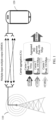
- FIG. 2 shows a terminal 10 according to some embodiments of this application.
- the terminal 10 may be implemented as the terminal 120 in the communications system shown in FIG. 1 .
- the terminal 10 may include input/output modules (including an audio input/output module 118, a key input module 116, a display 120, and the like), a user interface 102, one or more terminal processors 104, a transmitter 106, a receiver 108, a coupler 110, an antenna 114, and a memory 112. These components may be connected by using a bus or in another manner, and the connection by using a bus is used as an example in FIG. 2 .
- a communications interface 101 may be used by the terminal 10 to communicate with another communications device, such as another terminal device or a base station.
- the antenna 114 may be configured to convert electromagnetic energy in a transmission line into an electromagnetic wave in free space, or convert an electromagnetic wave in free space into electromagnetic energy in a transmission line.
- the terminal is provided with a plurality of antennas to support a MIMO function.
- the coupler 110 is configured to divide a communication signal received by the antenna 114 into a plurality of signals, and allocate the plurality of signals to a plurality of receivers 108.
- the transmitter 106 may be configured to transmit a signal that is output by the terminal processor 104.
- the receiver 108 may be configured to receive a signal received by the antenna 114.
- the transmitter 106 and the receiver 108 may be considered as a wireless modem. There may be one or more transmitters 106 and receivers 108 in the terminal 10.
- the terminal 10 may further include other communications components, such as a GPS module, a Bluetooth (Bluetooth) module, and a Wireless Fidelity (Wireless Fidelity, Wi-Fi) module.
- the input/output modules may be configured to implement interaction between the terminal 10 and a user/an external environment, and may mainly include the audio input/output module 118, the key input module 116, the display 120, and the like. In specific implementation, the input/output modules may further include a camera, a touchscreen, a sensor, and the like. All the input/output modules communicate with the terminal processor 104 by using the user interface 102.
- the memory 112 is coupled to the terminal processor 104, and is configured to store various software programs and/or a plurality of sets of instructions.
- the memory 112 may include a high-speed random access memory, or may include a nonvolatile memory, such as one or more magnetic disk storage devices, a flash memory device, or another nonvolatile solid-state storage device.
- the memory 112 may store an operating system (hereinafter referred to as a system), for example, an embedded operating system such as Android, iOS, Windows, or Linux.
- the memory 112 may further store a network communications program.
- the network communications program may be used to communicate with one or more auxiliary devices, one or more terminal devices, and one or more network devices.
- the memory 112 may further store a user interface program.
- the user interface program may vividly display content of an application program by using a graphical operation interface, and receive, by using an input control such as a menu, a dialog box, or a button, a control operation performed on the application program by the user.
- the memory 112 may be configured to store a program for implementing a radio resource configuration adjustment method on a side of the terminal 10 according to one or more embodiments of this application.
- a radio resource configuration adjustment method for implementation of the radio resource configuration adjustment method provided in one or more embodiments of this application, refer to subsequent embodiments.
- the terminal processor 104 may be configured to read and execute a computer readable instruction.
- the terminal processor 14 may be configured to: invoke a program stored in the memory 112, for example, the program for implementing the radio resource configuration adjustment method on the side of the terminal 10 according to one or more embodiments of this application; and execute an instruction included in the program.
- the terminal 10 shown in FIG. 2 is merely an implementation of the embodiments of the present invention. In actual application, the terminal 10 may further include more or fewer components. This is not limited herein.
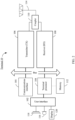
- FIG. 3 shows a network device 20 according to some embodiments of this application.
- the network device 20 may be implemented as the network device 110 in the communications system shown in FIG. 1 .
- the network device 20 may include a communications interface 203, one or more network device processors 201, a transmitter 207, a receiver 209, a coupler 211, an antenna 213, and a memory 205. These components may be connected by using a bus or in another manner, and the connection by using a bus is used as an example in FIG. 3 .
- the communications interface 203 may be used by the network device 20 to communicate with another communications device, such as another terminal or another network device.
- the communications interface 203 may be a network communications interface, such as an LTE (4G) communications interface or a 5G or future New Radio communications interface.
- the communications interface is not limited to a wireless communications interface.
- the network device 20 may be further provided with a wired communications interface to support wired communication. For example, a backhaul link between network devices 20 is a wired communication connection.
- the antenna 213 may be configured to convert electromagnetic energy in a transmission line into an electromagnetic wave in free space, or convert an electromagnetic wave in free space into electromagnetic energy in a transmission line.
- the network device 20 is provided with a plurality of antennas to support a MIMO function.
- the coupler 211 may be configured to divide a communication signal into a plurality of signals, and allocate the plurality of signals to a plurality of receivers 209.
- the transmitter 207 may be configured to transmit a signal that is output by the network device processor 201, and transmit a signal to another network device or another terminal.
- the receiver 209 may be configured to receive a signal received by the antenna 213, and receive a signal transmitted by another network device or another terminal.
- the transmitter 207 and the receiver 209 may be considered as a wireless modem. There may be one or more transmitters 207 and receivers 209 in the network device 20.
- the memory 205 is coupled to the network device processor 201, and is configured to store various software programs and/or a plurality of sets of instructions.
- the memory 205 may include a high-speed random access memory, or may include a nonvolatile memory, such as one or more magnetic disk storage devices, a flash memory device, or another nonvolatile solid-state storage device.
- the memory 205 may store an operating system (hereinafter referred to as a system), for example, an embedded operating system such as uCOS, VxWorks, or RTLinux.
- the memory 205 may further store a network communications program.
- the network communications program may be used to communicate with one or more auxiliary devices, one or more terminal devices, and one or more network devices.
- the memory 205 may be configured to store a program for implementing a radio resource configuration adjustment method on a side of the network device 20 according to one or more embodiments of this application.
- a radio resource configuration adjustment method for implementation of the radio resource configuration adjustment method provided in one or more embodiments of this application, refer to subsequent embodiments.
- the network device processor 201 may be configured to perform radio channel management, calling, communication link establishment and disconnection, cell handover control of user equipment in a current control area, and the like.
- the network device processor 201 may include an administration module/communication module (Administration Module/Communication Module, AM/CM) (a center for speech channel switching and information exchanging), a basic module (Basic Module, BM) (configured to complete call processing, signaling processing, radio resource management, radio link management, and circuit maintenance functions), a transcoder and submultiplexer (Transcoder and Submultiplexer, TCSM) (configured to complete multiplexing/demultiplexing and transcoding functions), and the like.
- Administration Module/communication module (Administration Module/Communication Module, AM/CM) (a center for speech channel switching and information exchanging)
- Basic Module, BM basic module
- Transcoder and submultiplexer Transcoder and Submultiplexer, TCSM
- the network device processor 201 may be configured to read and execute a computer readable instruction. Specifically, the network device processor 201 may be configured to: invoke a program stored in the memory 205, for example, the program for implementing the radio resource configuration adjustment method on the side of the network device 20 according to one or more embodiments of this application; and execute an instruction included in the program.
- the network device 20 may be implemented as a base transceiver station, a wireless transceiver, a basic service set (BSS), an extended service set (ESS), a NodeB, an eNodeB, or the like.
- the network device 20 may be implemented as base stations of several different types, such as a macro base station or a micro base station.
- the network device 20 may support different wireless technologies, such as a cell radio access technology or a WLAN radio access technology.
- the network device 20 shown in FIG. 3 is merely an implementation of the embodiments of the present invention. In actual application, the network device 20 may further include more or fewer components. This is not limited herein.
- an embodiment of the present invention provides a radio resource configuration adjustment method, to alleviate an overheating problem of the terminal when the overheating problem occurs because the terminal implements high-speed data transmission through carrier aggregation or MIMO.
- a terminal reports, to a network device, a message used to request the network device to reduce a radio resource configuration of the terminal.
- the network device sends, to the terminal, a message used to instruct the terminal to reduce the radio resource configuration.
- the terminal reduces the radio resource configuration, to alleviate the overheating problem.
- the terminal reports, to the network device, a message used to request the network device to increase the radio resource configuration of the terminal.
- the network device sends, to the terminal, a message used to instruct the terminal to increase the radio resource configuration.
- the terminal increases the radio resource configuration according to the message, to implement high-speed data transmission. In this way, the terminal can alleviate the overheating problem without network disconnection, and implement an as high as possible data transmission rate after alleviating the overheating problem.
- all messages reported to the network device may be referred to as first messages, and all messages sent by the network device to the terminal may be referred to as response messages.
- Step 1 When UE detects an overheating problem, the UE determines a cause of the problem.
- How the UE detects the overheating problem and determines the cause of the overheating problem is determined by the user equipment.
- Step 2 When the UE determines that the problem can be resolved by reducing a quantity of activated SCells, an RRC layer of the UE triggers a message reporting process.
- the message reporting process is used to notify a base station that the overheating problem currently occurs in the UE or the overheating problem is resolved.
- An overheating problem indication message reported to the base station includes one piece of assistance information.
- the assistance information includes the following content.
- Option 1 a quantity of activated-state SCells that can be supported by the UE, or a quantity of activated-state downlink SCells that can be supported by the UE and/or a quantity of activated-state uplink SCells that can be supported by the UE.
- the assistance information may include more-detailed information.
- the quantity of SCells may be a quantity of SCells on intra-band contiguous CCs, and/or a quantity of SCells on intra-band non-contiguous CCs, and/or a quantity of SCells on inter-band non-contiguous CCs.
- Option 2 an SCellIndex of an SCell expected by the UE to remain in an activated state, or an SCellIndex of a downlink SCell expected by the UE to remain in an activated state and/or an SCellIndex of an uplink SCell expected by the UE to remain in an activated state.
- Option 3 a quantity of SCells whose deactivation is expected by the UE, or a quantity of downlink SCells whose deactivation is expected by the UE and/or a quantity of uplink SCells whose deactivation is expected by the UE.
- the assistance information may include more-detailed information.
- the quantity of SCells may be a quantity of SCells on intra-band contiguous CCs, and/or a quantity of SCells on intra-band non-contiguous CCs, and/or a quantity of SCells on inter-band non-contiguous CCs.
- Option 4 an SCellIndex of an SCell whose deactivation is expected by the UE, or an SCellIndex of a downlink SCell whose deactivation is expected by the UE, and/or an SCellIndex of an uplink SCell whose deactivation is expected by the UE.
- Option 5 content indicating that the overheating problem of the UE is caused by currently activating excessive carriers.
- a condition for example, a temperature of the UE for triggering the message reporting process by the UE is determined by the user equipment.
- Option 6 a quantity of configured component carriers/serving cells/SCells that can be supported by the UE, or a quantity of configured downlink component carriers/serving cells/SCells that can be supported by the UE and/or a quantity of configured uplink component carriers/serving cells/SCells that can be supported by the UE.
- the assistance information may include more-detailed information.
- the quantity of component carriers/serving cells/SCells may be classified into a quantity of intra-band contiguous CCs/serving cells/SCells, and/or a quantity of intra-band non-contiguous CCs/serving cells/SCells, and/or a quantity of inter-band non-contiguous CCs/serving cells/SCells.
- Option 7 an SCellIndex of a configured SCell that can be supported by the UE, or an SCellIndex of a configured downlink SCell that can be supported by the UE and/or an SCellIndex of a configured uplink SCell that can be supported by the UE.
- Option 8 a quantity of component carriers/serving cells/SCells whose release is expected by the UE, or a quantity of downlink component carriers/serving cells/SCells whose release is expected by the UE, and/or a quantity of uplink component carriers/serving cells/SCells whose release is expected by the UE.
- the assistance information may include more-detailed information.
- the quantity of component carriers/serving cells/SCells may be classified into a quantity of intra-band contiguous CCs/serving cells/SCells, and/or a quantity of intra-band non-contiguous CCs/serving cells/SCells, and/or a quantity of inter-band non-contiguous CCs/serving cells/SCells.
- Option 9 an SCellIndex of an SCell whose release is expected by the UE, or an SCellIndex of a downlink SCell whose release is expected by the UE and/or an SCellIndex of an uplink SCell whose release is expected by the UE.
- Step 3 After the base station receives the overheating problem indication message reported by the UE, if the overheating problem indication message includes information about a quantity of activated-state SCells that can be currently supported by the UE, the base station determines whether to deactivate an SCell for the UE and determines which SCell is to be deactivated, or determines whether to release a configured component carrier/serving cell/SCell for the UE.
- a Media Access Control (Medium Access Control, MAC) layer of the base station If a decision result of the base station is to deactivate an SCell for the UE, a Media Access Control (Medium Access Control, MAC) layer of the base station generates activation/deactivation control signaling (Activation/Deactivation MAC CE), indicates the SCell that shall (shall) be deactivated in the activation/deactivation MAC CE, and sends the SCell to the UE. If a decision result of the base station is not to deactivate any SCell for the UE, the base station does not need to send any message to the UE.
- MAC Media Access Control
- Step 4 After the message in step 2 is sent, the following operations are performed.
- the UE deactivates a corresponding SCell according to an instruction of the base station.
- the UE may choose to de-register from a network, and then re-register with the network.
- the UE reports, to the base station in a radio access capability report message, a carrier aggregation capability that can be actually supported by the UE for currently alleviating the heat problem.
- a length of the waiting time is determined by the UE, or configured by the base station for the UE by using dedicated RRC signaling or system information, or pre-stipulated in a standard.
- Step 5 After the heat problem of the UE is alleviated without de-registration from a network and re-registration with the network, an RRC layer of the UE triggers a message reporting process.
- the message reporting process is used to notify a base station that the overheating problem currently occurs in the UE or the overheating problem is resolved.
- the overheating problem indication message reported to the base station does not include any assistance information.
- Step 6 After the base station receives the overheating problem indication message that is reported by the UE and that does not include any assistance information, the base station learns that the above-mentioned overheating problem of the UE is alleviated, and the base station determines whether to activate more SCells for the UE and determines which SCell is to be activated, or determines whether to add a component carrier/a serving cell/an SCell for the UE. If a decision result of the base station is to activate an SCell for the UE, a MAC layer of the base station generates an activation/deactivation MAC CE, indicates the SCell that shall (shall) be activated in the activation/deactivation MAC CE, and sends the SCell to the UE. If a decision result of the base station is not to activate any SCell for the UE, the base station does not need to send any message to the UE.
- Step 1 When UE detects an overheating problem, the UE determines a cause of the problem.
- How the UE detects the overheating problem and determines the cause of the overheating problem is determined by the user equipment.
- Step 2 When the UE determines that the problem can be resolved by reducing a quantity of activated SCells, an RRC layer of the UE triggers a message reporting process.
- the message reporting process is used to notify a base station of an updated radio access capability of the UE.
- the message reported to the base station includes various band combinations that can be currently supported by the UE and various downlink bandwidth classes and/or various uplink bandwidth classes that can be supported on each band in each band combination.
- a condition for example, a temperature of the UE for triggering the message reporting process by the UE is determined by the user equipment.
- Step 3 After the base station receives the foregoing message reported by the UE, the base station determines whether to accept an updated carrier aggregation capability of the UE, and notifies the UE of a decision result by using an RRC message.
- the decision result notification message may be an RRCConnectionReconfiguration message, or may be a newly defined RRC message.
- the base station adjusts, by using the RRCConnectionReconfiguration message, a quantity of carriers and a carrier frequency that are configured for the UE; or if the base station rejects the updated carrier aggregation capability of the UE, the base station does not send any message to the UE.
- Step 4 After the message in step 2 is sent, the following operations are performed.
- the UE If the UE receives the RRCConnectionReconfiguration message that is sent by the base station and that is used to adjust the quantity of carriers and the carrier frequency that are configured for the UE, the UE performs carrier reconfiguration according to an instruction of the base station.
- the UE may choose to de-register from a network, and then re-register with the network.
- the UE reports, to the base station in a radio access capability report message, a carrier aggregation capability that can be actually supported by the UE for currently alleviating the heat problem.
- a length of the waiting time is determined by the UE, or configured by the base station for the UE by using dedicated RRC signaling or system information, or pre-stipulated in a standard.
- Step 5 After the heat problem of the UE is alleviated without de-registration from a network and re-registration with the network, an RRC layer of the UE triggers a message reporting process.
- the message reporting process is used to notify a base station of an updated radio access capability of the UE.
- the message reported to the base station includes various band combinations that can be currently supported by the UE and a bandwidth class that can be supported on each band in each band combination, or includes indication information that can be used to restore a previous carrier aggregation configuration.
- the base station can learn, according to the indication information, that the UE restores a carrier aggregation configuration capability reported by the UE in a capability report message, so that the base station can configure and activate an SCell for the UE based on the capability.
- Step 6 After the base station receives the foregoing message reported by the UE, the base station determines whether to accept an updated carrier aggregation capability of the UE, and notifies the UE of a decision result by using an RRC message.
- the decision result notification message may be the RRCConnectionReconfiguration message, or may be a newly defined RRC message.
- the base station adjusts, by using the RRCConnectionReconfiguration message, a quantity of carriers and a carrier frequency that are configured for the UE; or if the base station rejects the updated carrier aggregation capability of the UE, the base station does not send any message to the UE.
- Step 1 When UE detects an overheating problem, the UE determines a cause of the problem.
- How the UE detects the overheating problem and determines the cause of the overheating problem is determined by the user equipment.
- Step 2 When the UE determines that the problem can be resolved by reducing a quantity of activated SCells, an RRC layer of the UE triggers a message reporting process.
- the message reporting process is used to notify a base station that a radio access capability of the UE is updated, and trigger the base station to re-obtain the updated radio access capability of the UE by using an existing UE capability obtaining process.
- the message reported to the base station includes a radio access capability update indication of the UE.
- a condition for example, a temperature of the UE for triggering the message reporting process by the UE is determined by the user equipment.
- Step 3 After the base station receives the foregoing message reported by the UE, the base station determines whether to re-obtain the updated radio access capability of the UE by using the existing UE capability obtaining process.
- Step 4 After the message in step 2 is sent, the following operations are performed.
- the UE reports the updated capability of the UE by using UECapabilityInformation.
- the reported capability includes at least an updated carrier aggregation capability of the UE.
- the reported capability includes various band combinations that can be currently supported by the UE and a bandwidth class that can be supported on each band in each band combination.
- the UE may choose to de-register from a network, and then re-register with the network.
- the UE reports, to the base station in a radio access capability report message, a carrier aggregation capability that can be actually supported by the UE for currently alleviating the heat problem.
- a length of the waiting time is determined by the UE, or configured by the base station for the UE by using dedicated RRC signaling or system information, or pre-stipulated in a standard.
- Step 5 After the heat problem of the UE is alleviated without de-registration from a network and re-registration with the network, an RRC layer of the UE triggers a message reporting process.
- the message reporting process is used to notify a base station that a radio access capability of the UE is updated, and trigger the base station to re-obtain the updated radio access capability of the UE by using an existing UE capability obtaining process.
- the message reported to the base station includes a radio access capability update indication of the UE.
- Step 6 After the base station receives the foregoing message reported by the UE, the base station determines whether to re-obtain the updated radio access capability of the UE by using the existing UE capability obtaining process.
- Step 1 When UE detects an overheating problem, the UE determines a cause of the problem.
- How the UE detects the overheating problem and determines the cause of the overheating problem is determined by the user equipment.
- Step 2 When the UE determines that the problem can be resolved by disabling a specific quantity of radio frequency receive links and a specific quantity of radio frequency transmit links, an RRC layer of the UE triggers a message reporting process.
- the message reporting process is used to notify a base station that the overheating problem currently occurs in the UE or the overheating problem is resolved.
- the message reported to the base station includes one piece of assistance information.
- the assistance information includes the following content.
- Option 1 a maximum quantity of downlink MIMO layers and/or a maximum quantity of uplink MIMO layers that can be currently supported by the UE.
- Option 2 a maximum quantity of downlink MIMO layers and/or a maximum quantity of uplink MIMO layers that can be supported by the UE in each serving cell configured by the base station for the UE.
- Option 3 a maximum quantity of downlink MIMO layers and/or a maximum quantity of uplink MIMO layers that can be supported by the UE on a frequency band corresponding to each serving cell configured by the base station for the UE.
- Option 4 content indicating that the overheating problem of the UE is caused by an excessive maximum quantity of downlink MIMO layers and/or an excessive maximum quantity of uplink MIMO layers that need to be currently supported.
- a condition for example, a temperature of the UE for triggering the message reporting process by the UE is determined by the user equipment.
- Step 3 After the base station receives an overheating problem indication message reported by the UE, if the overheating problem indication message includes information about a maximum quantity of downlink MIMO layers and/or a maximum quantity of uplink MIMO layers that can be currently supported by the UE, the base station determines whether to reduce the maximum quantity of downlink MIMO layers and/or the maximum quantity of uplink MIMO layers of the UE. If a decision result of the base station is to reduce the maximum quantity of downlink MIMO layers and the maximum quantity of uplink MIMO layers of the UE, the base station reconfigures the maximum quantity of downlink MIMO layers and/or the maximum quantity of uplink MIMO layers for the UE by using an RRC connection reconfiguration process. If a decision result of the base station is not to reduce the maximum quantity of downlink MIMO layers and/or the maximum quantity of uplink MIMO layers of the UE, the base station does not need to send any message to the UE.
- Step 4 After the message in step 2 is sent, the following operations are performed.
- the UE If the UE receives an RRCConnectionReconfiguration message that is sent by the base station and that is used to reduce the maximum quantity of downlink MIMO layers and/or the maximum quantity of uplink MIMO layers of the UE, the UE disables a corresponding quantity of radio frequency receive links and a corresponding quantity of radio frequency transmit links.
- the UE may choose to de-register from a network, and then re-register with the network.
- the UE reports, to the base station in a radio access capability report message, a MIMO capability that can be actually supported by the UE for currently alleviating the heat problem.
- a length of the waiting time is determined by the UE, or configured by the base station for the UE by using dedicated RRC signaling or system information, or pre-stipulated in a standard.
- Step 5 After the heat problem of the UE is alleviated without de-registration from a network and re-registration with the network, an RRC layer of the UE triggers a message reporting process.
- the message reporting process is used to notify a base station that the overheating problem currently occurs in the UE or the overheating problem is resolved.
- the message reported to the base station does not include any assistance information.
- Step 6 After the base station receives the overheating problem indication message that is reported by the UE and that does not include any assistance information, the base station learns that the above-mentioned overheating problem of the UE is alleviated, and the base station determines whether to restore a maximum quantity of downlink MIMO layers and/or a maximum quantity of uplink MIMO layers that are configured for the UE. If a decision result of the base station is to restore the maximum quantity of downlink MIMO layers and/or the maximum quantity of uplink MIMO layers that are configured for the UE, the base station reconfigures the maximum quantity of downlink MIMO layers and/or the maximum quantity of uplink MIMO layers for the UE by using an RRC connection reconfiguration process. If a decision result of the base station is not to restore the maximum quantity of downlink MIMO layers and/or the maximum quantity of uplink MIMO layers that are configured for the UE, the base station does not need to send any message to the UE.
- Step 1 When UE detects an overheating problem, the UE determines a cause of the problem.
- How the UE detects the overheating problem and determines the cause of the overheating problem is determined by the user equipment.
- Step 2 When the UE determines that the problem can be resolved by disabling a specific quantity of radio frequency receive links and a specific quantity of radio frequency transmit links, an RRC layer of the UE triggers a message reporting process.
- the message reporting process is used to notify a base station of an updated radio access capability of the UE.
- the message reported to the base station includes each band that can be currently supported by the UE and a downlink MIMO capability and/or an uplink MIMO capability that can be correspondingly supported on each band, and/or various band combinations and a downlink MIMO capability that can be correspondingly supported in each supported downlink bandwidth class on each band in each band combination and/or an uplink MIMO capability that can be correspondingly supported in each supported uplink bandwidth class on each band in each band combination.
- a condition for example, a temperature of the UE for triggering the message reporting process by the UE is determined by the user equipment.
- Step 3 After the base station receives the foregoing message reported by the UE, the base station determines whether to accept an updated MIMO capability of the UE, and notifies the UE of a decision result by using an RRC message.
- the decision result notification message may be the RRCConnectionReconfiguration message, or may be a newly defined RRC message.
- the base station reconfigures, by using the RRCConnectionReconfiguration message, a quantity of downlink MIMO layers and/or a quantity of uplink MIMO layers for the UE; or if the base station rejects the updated MIMO of the UE, the base station does not send any message to the UE.
- Step 4 After the message in step 2 is sent, the following operations are performed.
- the UE If the UE receives the RRC message that is sent by the base station and that is used to accept the updated MIMO capability of the UE, the UE disables a corresponding quantity of radio frequency receive links and a corresponding quantity of radio frequency transmit links.
- the UE may choose to de-register from a network, and then re-register with the network.
- the UE reports, to the base station in a radio access capability report message, a MIMO capability that can be actually supported by the UE for currently alleviating the heat problem.
- a length of the waiting time is determined by the UE, or configured by the base station for the UE by using dedicated RRC signaling or system information, or pre-stipulated in a standard.
- Step 5 After the heat problem of the UE is alleviated without de-registration from a network and re-registration with the network, an RRC layer of the UE triggers a message reporting process.
- the message reporting process is used to notify a base station of an updated radio access capability of the UE.
- the message reported to the base station includes each band that can be currently supported by the UE, a downlink MIMO capability and/or an uplink MIMO capability that can be correspondingly supported on each band, various band combinations that can be currently supported by the UE, and a downlink MIMO capability that can be correspondingly supported in each supported downlink bandwidth class on each band in each band combination and/or an uplink MIMO capability that can be correspondingly supported in each supported uplink bandwidth class on each band in each band combination.
- Step 6 After the base station receives the foregoing message reported by the UE, the base station determines whether to accept an updated MIMO capability of the UE, and notifies the UE of a decision result by using an RRC message.
- the decision result notification message may be the RRCConnectionReconfiguration message, or may be a newly defined RRC message.
- the base station reconfigures, by using the RRCConnectionReconfiguration message, a quantity of downlink MIMO layers and/or a quantity of uplink MIMO layers for the UE; or if the base station rejects the updated MIMO of the UE, the base station does not send any message to the UE.
- Step 1 When UE detects an overheating problem, the UE determines a cause of the problem.
- How the UE detects the overheating problem and determines the cause of the overheating problem is determined by the user equipment.
- Step 2 When the UE determines that the problem can be resolved by disabling a specific quantity of radio frequency receive links and a specific quantity of radio frequency transmit links, an RRC layer of the UE triggers a message reporting process.
- the message reporting process is used to notify a base station that a radio access capability of the UE is updated, and trigger the base station to re-obtain the updated radio access capability of the UE by using an existing UE capability obtaining process.
- the message reported to the base station includes a radio access capability update indication of the UE.
- a condition for example, a temperature of the UE for triggering the message reporting process by the UE is determined by the user equipment.
- Step 3 After the base station receives the foregoing message reported by the UE, the base station determines whether to re-obtain the updated radio access capability of the UE by using the existing UE capability obtaining process.
- Step 4 After the message in step 2 is sent, the following operations are performed.
- the UE reports the updated capability of the UE by using UECapabilityInformation.
- the reported capability includes at least an updated MIMO capability of the UE.
- the reported capability includes various band combinations that can be currently supported by the UE, and a downlink MIMO capability that can be correspondingly supported in each supported downlink bandwidth class on each band in each band combination and/or an uplink MIMO capability that can be correspondingly supported in each supported uplink bandwidth class on each band in each band combination.
- the UE may choose to de-register from a network, and then re-register with the network.
- the UE reports, to the base station in a radio access capability report message, a MIMO capability that can be actually supported by the UE for currently alleviating the heat problem.
- a length of the waiting time is determined by the UE, or configured by the base station for the UE by using dedicated RRC signaling or system information, or pre-stipulated in a standard.
- Step 5 After the heat problem of the UE is alleviated without de-registration from a network and re-registration with the network, an RRC layer of the UE triggers a message reporting process.
- the message reporting process is used to notify a base station that a radio access capability of the UE is updated, and trigger the base station to re-obtain the updated radio access capability of the UE by using an existing UE capability obtaining process.
- the message reported to the base station includes a radio access capability update indication of the UE.
- Step 6 After the base station receives the foregoing message reported by the UE, the base station determines whether to re-obtain the updated radio access capability of the UE by using the existing UE capability obtaining process.
- Both the assistance information related to carrier aggregation and the assistance information related to MIMO in the foregoing embodiments may be included in a message reported by the UE.
- the network device may further notify the user equipment whether the user equipment can report the message.
- the network device may notify, by using the following two methods, the terminal whether the terminal can report the first message.
- a timer needs to be configured for the UE, and the timer is used to control whether the UE can initiate message transmission in the message reporting process.
- the message reporting process initiated by the UE may be any message reporting process in Embodiment 1 to Embodiment 7.
- a specific implementation is as follows:
- the UE When the UE needs to initiate any message reporting process in Embodiment 1 to Embodiment 6, if content of a currently reported message is the same as content of a message reported in a previously initiated message reporting process, the user equipment cannot initiate the message reporting process. If the content of the currently reported message is different from the content of the message reported in the previously initiated message reporting process, the UE checks whether a timer runs, where the timer is configured by the base station for the UE and is used to control the UE to initiate the message reporting. If the timer runs, the UE cannot initiate a currently required message reporting process; otherwise, if the timer does not run, the UE may initiate a currently required message reporting process.
- the UE When the UE initiates the message reporting process, the UE starts or restarts the timer used to control the UE to initiate the message reporting.
- the foregoing method further includes the following features.
- the UE may use a fact whether the base station configures the timer for the UE as an implicit indication of whether the base station supports the message reporting process initiated by the UE in Embodiment 1 to Embodiment 6. In other words, when the UE receives the timer configured by the base station for the UE, the UE can initiate the message reporting process; otherwise, the UE cannot initiate the message reporting process.
- a length of the timer may be configured by the base station, or may be a value that is preset in a protocol. If the length of the timer is configured by the base station, the base station may configure the length by using dedicated signaling or may configure the length in a system message. If configuration is performed by using the dedicated signaling, the length and the indication information that is used to notify the UE whether the message reporting process in Embodiment 1 to Embodiment 6 can be initiated may be simultaneously configured in a same message; or only the length of the timer may be configured, without configuring the indication information.
- the source base station When a source base station of the UE triggers the UE to perform a handover, if the source base station previously receives a message reported by the UE in step 2 in any manner in Embodiment 1 to Embodiment 6, the source base station adds, to a handover request message to be sent to a target base station, the message reported by the UE.
- the message may be used as content of access stratum context (AS context) information included in a handover preparation message.
- AS context access stratum context
- the handover request message sent by the source base station to the target base station further includes indication information that is configured by the source base station for the UE and that is used to notify the UE whether the message reporting process in Embodiment 1 to Embodiment 6 can be initiated, and/or a value of the timer used to control whether the UE can initiate message transmission in the message reporting process in Embodiment 1 to Embodiment 6.
- the message may be used as content of AS Config information included in the handover preparation message.
- the UE When the UE receives an RRCConnectionReconfiguration message that is sent by a current serving cell and that includes MobilityControlInfo, if the UE sends, to the serving cell T ms before a current time in any manner in Embodiment 1 to Embodiment 6, the message reported in step 2, and if a target cell of the UE also supports the UE in initiating the message reporting process in any manner in Embodiment 1 to Embodiment 6, the UE initiates the message reporting process in a new serving cell in any manner in Embodiment 1 to Embodiment 6.
- a length of T may be a numeric value that is preset in a protocol, or may be configured by the base station by using a dedicated message or a system message.
- the UE after the user equipment accesses a network, when the UE supports the foregoing message reporting capability, the UE needs to add, to a radio capability report message, indication information used to indicate that the UE supports the foregoing message reporting.
- the base station may determine, based on the indication information included in a capability message reported by the UE, specific UE to which indication information of a side of the base station and/or a value configuration of the timer need/needs to be delivered.
- CA+MIMO Carrier aggregation is introduced from the 3GPP standard Release 10.
- CA+MIMO products keep pursuing a high rate and are continually upgraded, to meet a market requirement.
- CAT categories of user equipment products are continually upgraded, and future products have categories over 1G CAT 16.
- the user equipment products are smaller and thinner in appearance.
- CA and MIMO are controlled through a single-direction instruction by a network in the 3GPP standard, and the user equipment passively performs execution.
- the UE cannot perform a service based on an actual situation due to a disadvantage that the CA+MIMO are controlled in a single direction by a system side.
- CA and MIMO can be dynamically and proactively controlled online, thereby providing excellent communication experience, and making contribution to proper scheduling of the UE on the system side.
- a basis for a new, smaller, and thinner design is provided for appearance of the user equipment as power consumption and heat are smoothly alleviated.
- the apparatuses provided in the apparatus embodiments are configured to execute the methods provided in the corresponding method embodiments. Therefore, for the apparatus embodiments, refer to related parts in the related method embodiments.
- the terminal when the overheating problem occurs in the terminal, the terminal can reduce, without network disconnection and with standard stipulations complied, a radio resource configuration according to an instruction of the network device, thereby alleviating the overheating problem.
- the terminal can increase, without network disconnection and with standard stipulations complied, the radio resource configuration according to an instruction of the network device, thereby implementing high-speed data transmission.
- Embodiment 1 A radio resource configuration adjustment method, comprising:
- Embodiment 2 The method according to Embodiment 1, wherein when the user equipment detects the overheating problem, the first message comprises assistance information; and the assistance information comprises: a quantity of activated-state downlink SCells supported by the user equipment and/or a quantity of activated-state uplink SCells supported by the user equipment.
- Embodiment 3 The method according to Embodiment 1, wherein when the user equipment detects that the overheating problem is alleviated, the first message does not comprise assistance information.
- Embodiment 4 The method according to any one of Embodiments 1 to 3, wherein
- Embodiment 5 The method according to Embodiment 4, wherein if content of the current first message is different from content of a previously reported first message, and the first timer does not run, the user equipment initiates reporting of the first message.
- Embodiment 6 The method according to any one of Embodiments 1 to 5, wherein the user equipment receives first indication information sent by the network device, wherein the first indication information is used to notify the user equipment whether the user equipment can report the first message.
- Embodiment 7 The method according to any one of Embodiments 1 to 6, wherein the user equipment sends a second message to the network device, wherein the second message comprises second indication information, and the second indication information is used to indicate whether the user equipment supports the first message.
- Embodiment 8 A radio resource configuration adjustment method, comprising:
- Embodiment 9 The method according to Embodiment 8, wherein
- Embodiment 10 The method according to Embodiment 8 or 9, wherein
- Embodiment 11 The method according to any one of Embodiments 8 to 10, wherein
- Embodiment 12 The method according to any one of Embodiments 8 to 11, wherein the network device sends a third message to the user equipment, wherein the third message comprises indication information used to notify the user equipment whether the user equipment can report the first message.
- Embodiment 13 The method according to any one of Embodiments 8 to 12, wherein the third message and the second message are a same message.
- Embodiment 14 The method according to any one of Embodiments 8 to 13, wherein the network device receives a fourth message sent by the user equipment, wherein the fourth message comprises indication information used to indicate whether the user equipment supports the first message.
- Embodiment 15 User equipment, comprising a transmitter, a receiver, and a processor, wherein the transmitter and the receiver are connected to the processor by using a bus;
- Embodiment 16 The equipment according to Embodiment 15, wherein when the processor detects the overheating problem, the first message comprises assistance information; and the assistance information comprises: a quantity of activated-state downlink SCells supported by the user equipment and/or a quantity of activated-state uplink SCells supported by the user equipment.
- Embodiment 17 The equipment according to Embodiment 15, wherein when the processor detects that the overheating problem is alleviated, the first message does not comprise assistance information.
- Embodiment 18 The equipment according to any one of Embodiments 15 to 17, wherein
- Embodiment 19 The equipment according to Embodiment 18, wherein if content of the current first message is different from content of a previously reported first message, and the first timer does not run, the transmitter initiates reporting of the first message.
- Embodiment 20 The equipment according to any one of Embodiments 15 to 19, wherein the receiver receives first indication information sent by the network device, wherein the first indication information is used to notify the user equipment whether the user equipment can report the first message.
- Embodiment 21 The equipment according to any one of Embodiments 15 to 20, wherein the transmitter sends a second message to the network device, wherein the second message comprises second indication information, and the second indication information is used to indicate whether the user equipment supports the first message.
- Embodiment 22 A network device, comprising a transmitter, a receiver, and a processor, wherein the transmitter and the receiver are connected to the processor by using a bus; the receiver receives a first message sent by the user equipment, wherein the first message is used to notify the network device that an overheating problem occurs in the user equipment or an overheating problem is alleviated; and the transmitter sends a response message to the user equipment, wherein the response message is used to instruct the user equipment to perform any one of the following operations: deactivating a secondary serving cell, activating a secondary serving cell, releasing a secondary serving cell, and adding a secondary serving cell.
- Embodiment 23 The device according to Embodiment 22, wherein
- Embodiment 24 The device according to Embodiment 22 or 23, wherein
- Embodiment 25 The device according to any one of Embodiments 22 to 24, wherein
- Embodiment 26 The device according to any one of Embodiments 22 to 25, wherein the network device sends a third message to the user equipment, wherein the third message comprises indication information used to notify the user equipment whether the user equipment can report the overheating problem.
- Embodiment 27 The device according to any one of Embodiments 22 to 26, wherein the third message and the second message are a same message.
- Embodiment 28 The device according to any one of Embodiments 22 to 26, wherein the receiver receives a fourth message sent by the user equipment, wherein the fourth message comprises indication information used to indicate whether the user equipment supports the first message.
- Embodiment 29 A communications system, comprising user equipment and a network device, wherein
- All or some of the foregoing embodiments may be implemented by using software, hardware, firmware, or any combination thereof.
- the embodiments may be implemented wholly or partially in a form of a computer program product.
- the computer program product includes one or more computer instructions.
- the computer may be a general-purpose computer, a dedicated computer, a computer network, or another programmable apparatus.
- the computer instructions may be stored in a computer-readable storage medium or may be transmitted from a computer-readable storage medium to another computer-readable storage medium.
- the computer instructions may be transmitted from a website, computer, server, or data center to another website, computer, server, or data center in a wired (for example, a coaxial cable, an optical fiber, or a digital subscriber line) or wireless (for example, infrared, radio, microwave, or the like) manner.
- the computer-readable storage medium may be any usable medium accessible by a computer, or a data storage device, such as a server or a data center, integrating one or more usable media.
- the usable medium may be a magnetic medium (for example, a floppy disk, a hard disk, or a magnetic tape), an optical medium (for example, a DVD), a semiconductor medium (for example, a solid state disk Solid State Disk), or the like.
Landscapes
- Engineering & Computer Science (AREA)
- Signal Processing (AREA)
- Computer Networks & Wireless Communication (AREA)
- Databases & Information Systems (AREA)
- Mobile Radio Communication Systems (AREA)
Applications Claiming Priority (4)
| Application Number | Priority Date | Filing Date | Title |
|---|---|---|---|
| CN201710026111 | 2017-01-13 | ||
| CN2017078228 | 2017-03-25 | ||
| EP18739190.9A EP3565298B1 (de) | 2017-01-13 | 2018-01-04 | Verfahren und vorrichtung zur anpassung der funkressourcenkonfiguration |
| PCT/CN2018/071414 WO2018130115A1 (zh) | 2017-01-13 | 2018-01-04 | 一种调整无线资源配置的方法、装置及系统 |
Related Parent Applications (2)
| Application Number | Title | Priority Date | Filing Date |
|---|---|---|---|
| EP18739190.9A Division-Into EP3565298B1 (de) | 2017-01-13 | 2018-01-04 | Verfahren und vorrichtung zur anpassung der funkressourcenkonfiguration |
| EP18739190.9A Division EP3565298B1 (de) | 2017-01-13 | 2018-01-04 | Verfahren und vorrichtung zur anpassung der funkressourcenkonfiguration |
Publications (1)
| Publication Number | Publication Date |
|---|---|
| EP4149149A1 true EP4149149A1 (de) | 2023-03-15 |
Family
ID=62839509
Family Applications (2)
| Application Number | Title | Priority Date | Filing Date |
|---|---|---|---|
| EP22177091.0A Pending EP4149149A1 (de) | 2017-01-13 | 2018-01-04 | Funkressourcenkonfigurations-einstellungsverfahren, -gerät und -system |
| EP18739190.9A Active EP3565298B1 (de) | 2017-01-13 | 2018-01-04 | Verfahren und vorrichtung zur anpassung der funkressourcenkonfiguration |
Family Applications After (1)
| Application Number | Title | Priority Date | Filing Date |
|---|---|---|---|
| EP18739190.9A Active EP3565298B1 (de) | 2017-01-13 | 2018-01-04 | Verfahren und vorrichtung zur anpassung der funkressourcenkonfiguration |
Country Status (8)
| Country | Link |
|---|---|
| US (2) | US11856514B2 (de) |
| EP (2) | EP4149149A1 (de) |
| JP (2) | JP6915063B2 (de) |
| KR (3) | KR102544376B1 (de) |
| CN (3) | CN115243283A (de) |
| AU (2) | AU2018208142C1 (de) |
| ES (1) | ES2926709T3 (de) |
| WO (1) | WO2018130115A1 (de) |
Families Citing this family (62)
| Publication number | Priority date | Publication date | Assignee | Title |
|---|---|---|---|---|
| KR102363440B1 (ko) | 2017-08-09 | 2022-02-15 | 베이징 시아오미 모바일 소프트웨어 컴퍼니 리미티드 | 사용자 디바이스의 과열 보호 방법, 장치, 사용자 디바이스 및 기지국 |
| WO2019056177A1 (zh) * | 2017-09-19 | 2019-03-28 | 北京小米移动软件有限公司 | 用户设备的过热保护方法、装置及基站 |
| US10524266B2 (en) | 2017-10-20 | 2019-12-31 | Google Llc | Switching transmission technologies within a spectrum based on network load |
| US11246143B2 (en) | 2017-12-15 | 2022-02-08 | Google Llc | Beamforming enhancement via strategic resource utilization |
| US11088750B2 (en) * | 2018-02-16 | 2021-08-10 | Qualcomm Incorporated | Feedback of beam switch time capability |
| US11251847B2 (en) | 2018-03-28 | 2022-02-15 | Google Llc | User device beamforming |
| CN111955039B (zh) | 2018-04-13 | 2024-02-09 | 谷歌有限责任公司 | 基于位置的资源调度 |
| US11490363B2 (en) | 2018-04-18 | 2022-11-01 | Google Llc | User device-initiated bandwidth request |
| US10609681B2 (en) | 2018-04-24 | 2020-03-31 | Google Llc | User device-initiated request for resource configuration |
| KR102616768B1 (ko) | 2018-06-12 | 2023-12-20 | 구글 엘엘씨 | 빔포밍 기반 무승인 비직교 다중 액세스 전송 |
| US11425699B2 (en) | 2018-06-15 | 2022-08-23 | Google Llc | CBG-based NOMA transmission for a wireless network |
| US11063705B2 (en) | 2018-06-18 | 2021-07-13 | Google Llc | Methods and apparatus for HARQ in NOMA transmission for 5G NR |
| EP3937542A1 (de) | 2018-06-21 | 2022-01-12 | Google LLC | Aufrechterhaltung von kommunikations- und signalisierungsschnittstellen durch einen donor-basisstations-handover |
| KR20210021066A (ko) | 2018-06-22 | 2021-02-24 | 구글 엘엘씨 | 멀티-브랜치 noma 무선 통신 |
| US11496958B2 (en) | 2018-08-08 | 2022-11-08 | Google Llc | Public land mobile network selection by user equipment in an inactive mode at a radio resource control layer |
| US11910391B2 (en) | 2018-08-10 | 2024-02-20 | Google Llc | Methods and apparatus for an uplink control channel in NOMA asynchronous transmissions |
| US11452169B2 (en) | 2018-08-15 | 2022-09-20 | Google Llc | Preventing inadvertent idle mode in multi-node connectivity environments |
| US10708969B2 (en) | 2018-09-04 | 2020-07-07 | Google Llc | Dual connectivity capability modification |
| US11233548B2 (en) | 2018-09-10 | 2022-01-25 | Google Llc | Fast beam tracking |
| US20200100178A1 (en) * | 2018-09-25 | 2020-03-26 | Apple Inc. | Controlling MIMO Layers for UE Power Saving |
| US11528597B2 (en) * | 2018-09-25 | 2022-12-13 | Mediatek Singapore Pte Ltd. | Carrier and frequency specific capability restrictions |
| EP3821672A1 (de) | 2018-09-26 | 2021-05-19 | Google LLC | Nicht-orthogonale mehrfachzugriffskonfiguration in geteilten basisstationsarchitekturen |
| KR102562310B1 (ko) | 2018-09-27 | 2023-08-01 | 삼성전자주식회사 | 적응적으로 성능을 변경하는 무선 통신장치 및 이의 동작방법 |
| GB2578688A (en) * | 2018-09-28 | 2020-05-20 | Samsung Electronics Co Ltd | Improvements in and relating to addressing overheating in user equipment in a telecommunication system |
| KR20210078482A (ko) | 2018-10-26 | 2021-06-28 | 구글 엘엘씨 | 리소스 제어 상태 변경 및 다중 노드 연결의 효율적인 처리 |
| KR20200050852A (ko) * | 2018-11-02 | 2020-05-12 | 삼성전자주식회사 | 전자 장치의 과열을 처리하기 위한 방법 및 장치 |
| WO2020091461A1 (en) * | 2018-11-02 | 2020-05-07 | Samsung Electronics Co., Ltd. | Method and apparatus for handling overheat of electronic device |
| US10925007B2 (en) * | 2018-11-02 | 2021-02-16 | Apple Inc. | Dynamic power reduction requests for wireless communications |
| CN112789902A (zh) * | 2018-11-12 | 2021-05-11 | 索尼公司 | 对辅助信息的信号通知进行网络管理的方法和设备 |
| US20200154267A1 (en) * | 2018-11-12 | 2020-05-14 | Qualcomm Incorporated | Configuring a maximum number of layers |
| AU2019396444B2 (en) | 2018-12-12 | 2023-02-23 | Google Llc | Facilitating self-organizing network (SON) enhancement |
| KR20200093662A (ko) | 2019-01-11 | 2020-08-05 | 구글 엘엘씨 | 5g nr 시스템에서 업링크 전송 방법 |
| CN111565464B (zh) * | 2019-02-14 | 2024-02-02 | 华为技术有限公司 | 传输信息的方法和装置 |
| CN114650589A (zh) | 2019-03-09 | 2022-06-21 | 荣耀终端有限公司 | 网络连接的处理方法、相关设备及计算机存储介质 |
| WO2020186097A1 (en) | 2019-03-12 | 2020-09-17 | Google Llc | User-equipment coordination set beam sweeping |
| US11503610B2 (en) | 2019-04-02 | 2022-11-15 | Google Llc | User equipment coordination for interference cancelation |
| CN113411830B (zh) * | 2019-04-23 | 2022-03-29 | 华为技术有限公司 | 传输信息的方法和装置 |
| CN113766558A (zh) * | 2019-05-16 | 2021-12-07 | Oppo广东移动通信有限公司 | 一种网络模式控制方法及终端、存储介质 |
| US10893572B2 (en) | 2019-05-22 | 2021-01-12 | Google Llc | User-equipment-coordination set for disengaged mode |
| US11641566B2 (en) | 2019-07-25 | 2023-05-02 | Google Llc | User-equipment-coordination-set regrouping |
| CN111836407B (zh) * | 2019-08-09 | 2023-09-15 | 维沃移动通信有限公司 | 处理方法和设备 |
| US11297576B2 (en) | 2019-08-12 | 2022-04-05 | Qualcomm Incorporated | Innovative signaling approaches to network for overheating indication in new radio (NR) and multi-radio dual connectivity (MR-DC) |
| US11350439B2 (en) | 2019-08-13 | 2022-05-31 | Google Llc | User-equipment-coordination-set control aggregation |
| CN112399645B (zh) * | 2019-08-15 | 2023-02-28 | 华为技术有限公司 | Scg释放方法、用户设备及网络设备 |
| EP3997798B1 (de) | 2019-09-19 | 2024-05-22 | Google LLC | Benutzergerätekoordinatenset-selektive teilnahme |
| EP4005101B1 (de) | 2019-09-19 | 2023-12-20 | Google LLC | Verbesserte strahlsuche für aktive koordinationssätze |
| WO2021092755A1 (zh) * | 2019-11-12 | 2021-05-20 | Oppo广东移动通信有限公司 | 一种上报辅助信息的方法及装置、终端设备、网络设备 |
| GB2593959A (en) * | 2019-12-12 | 2021-10-13 | Samsung Electronics Co Ltd | Improvements in and relating to telecommunications systems |
| CN113037916B (zh) * | 2019-12-25 | 2022-04-22 | 深圳市万普拉斯科技有限公司 | 信息传输组合配置方法、装置和移动终端 |
| CN114071786A (zh) * | 2020-07-31 | 2022-02-18 | 华为技术有限公司 | 一种网络连接方法、系统及相关装置 |
| CN114389651B (zh) * | 2020-10-21 | 2023-06-23 | 华为技术有限公司 | 调度数据传输的方法和通信装置 |
| WO2022141502A1 (zh) * | 2020-12-31 | 2022-07-07 | 华为技术有限公司 | 一种通信方法及装置 |
| BR112023020143A2 (pt) * | 2021-04-01 | 2023-12-12 | Ericsson Telefon Ab L M | Método para manusear operação de grupo de células secundárias em uma rede de comunicações sem fio, portador, equipamento de usuário, e, nó de rede |
| GB2608259A (en) * | 2021-05-11 | 2022-12-28 | Samsung Electronics Co Ltd | Improvements in and relating to Quality of Experience, QoE, reporting in a telecommunication network |
| CN113329423B (zh) * | 2021-05-21 | 2022-09-06 | Oppo广东移动通信有限公司 | 网络连接的控制方法、装置、终端设备及计算机存储介质 |
| CN113301559B (zh) * | 2021-05-21 | 2022-08-02 | 维沃移动通信(杭州)有限公司 | 终端能力上报方法、装置和电子设备 |
| US11663907B2 (en) * | 2021-06-21 | 2023-05-30 | Ettifos Co. | Method and apparatus for transmitting and receiving vehicle-to-pedestrian (V2P) message |
| CN117941435A (zh) * | 2021-09-06 | 2024-04-26 | 中兴通讯股份有限公司 | 在无线网络中用于节能的方法、设备和系统 |
| WO2023050153A1 (zh) * | 2021-09-29 | 2023-04-06 | 北京小米移动软件有限公司 | 一种上报方法、装置、用户设备、网路侧设备及存储介质 |
| EP4170952A1 (de) * | 2021-10-20 | 2023-04-26 | Nokia Solutions and Networks Oy | S-zellen-konfiguration in gnb |
| CN114845366B (zh) * | 2022-05-30 | 2023-10-27 | 中国电信股份有限公司 | 基站的唤醒方法及系统、用户终端、基站、存储介质 |
| WO2024058383A1 (ko) * | 2022-09-13 | 2024-03-21 | 삼성전자주식회사 | 소모 전류와 발열을 저감시킬 수 있는 전자 장치, 기지국 장치 및 이들의 제어 방법 |
Citations (3)
| Publication number | Priority date | Publication date | Assignee | Title |
|---|---|---|---|---|
| US20100323743A1 (en) * | 2009-06-17 | 2010-12-23 | Hong Xin George Huan | Thermal energy control in a mobile transceiver |
| US20160127998A1 (en) * | 2014-11-03 | 2016-05-05 | Intel Corporation | Communication terminal and method for controlling power consumption of a communication terminal |
| WO2017099891A1 (en) * | 2015-12-07 | 2017-06-15 | Intel IP Corporation | Systems, methods, and devices to prevent overheating from high performance device configurations in wireless networks |
Family Cites Families (40)
| Publication number | Priority date | Publication date | Assignee | Title |
|---|---|---|---|---|
| US6760311B1 (en) | 1998-11-20 | 2004-07-06 | Ericsson Inc. | Thermal transmission control of wireless data modem |
| US20080046132A1 (en) * | 2006-08-18 | 2008-02-21 | Nokia Corporation | Control of heat dissipation |
| KR100954820B1 (ko) * | 2007-01-22 | 2010-04-28 | 이노베이티브 소닉 리미티드 | 무선통신시스템에서 다중입력 다중출력(mimo)프로세스를 개선하는 방법 및 장치 |
| CN101647330B (zh) | 2007-03-30 | 2012-05-23 | 日本电气株式会社 | 散热结构及便携式设备 |
| US8086229B2 (en) | 2008-02-25 | 2011-12-27 | Telefonaktiebolaget L M Ericsson (Publ) | Alleviating mobile device overload conditions in a mobile communication system |
| CN101753658A (zh) * | 2008-10-31 | 2010-06-23 | 华为终端有限公司 | 调节终端温度的方法、温度调节装置及终端 |
| KR101299169B1 (ko) | 2008-11-24 | 2013-12-11 | 퀄컴 인코포레이티드 | 중복 패킷 전송들을 최소화하기 위하여 적응적 tsp 세팅하기 위한 장치 및 방법 |
| JP5059800B2 (ja) * | 2009-03-16 | 2012-10-31 | 株式会社エヌ・ティ・ティ・ドコモ | 無線基地局装置及び移動局装置、無線通信方法 |
| US8902797B2 (en) * | 2009-08-11 | 2014-12-02 | Empire Technology Development Llc | Approach for optimizing energy consumption of multiple-input multiple-output system |
| CN101834644A (zh) * | 2010-02-04 | 2010-09-15 | 华为终端有限公司 | 一种无线终端的辅天线状态控制方法及无线终端 |
| JP5482325B2 (ja) * | 2010-03-12 | 2014-05-07 | 富士通モバイルコミュニケーションズ株式会社 | 無線通信装置 |
| JP5387483B2 (ja) * | 2010-03-31 | 2014-01-15 | 富士通株式会社 | 無線通信に用いられる装置、プログラム及び方法 |
| CN102625421A (zh) | 2011-01-27 | 2012-08-01 | 中兴通讯股份有限公司 | 一种用户设备的节电方法和系统 |
| KR20130007737A (ko) * | 2011-07-11 | 2013-01-21 | 삼성전자주식회사 | 자원 할당 방법 및 장치 |
| US9019880B2 (en) * | 2011-08-11 | 2015-04-28 | Qualcomm Incorporated | Methods and apparatus for overload mitigation using uplink transmit power backoff |
| JP2013040254A (ja) | 2011-08-12 | 2013-02-28 | Nitto Denko Corp | 導電性粘着テープ |
| CN103176889B (zh) * | 2011-12-21 | 2016-08-17 | 伊姆西公司 | 用于设备过温保护的方法和装置 |
| US9019836B2 (en) * | 2012-02-03 | 2015-04-28 | Qualcomm Incorporated | Downlink data transfer flow control during carrier aggregation |
| JP5559236B2 (ja) * | 2012-04-18 | 2014-07-23 | Necアクセステクニカ株式会社 | 無線通信装置および無線通信方法 |
| US9693306B2 (en) * | 2012-07-11 | 2017-06-27 | Blackberry Limited | Mechanisms to support UE power preference signaling |
| US9521544B2 (en) * | 2012-08-03 | 2016-12-13 | Telefonaktiebolaget Lm Ericsson (Publ) | Availability of modes of communication |
| EP2819481A1 (de) * | 2013-06-28 | 2014-12-31 | Gemalto M2M GmbH | Konfiguration und Rekonfiguration einer Funkverbindung hinsichtlich einer Betriebstemperatur eines Benutzergeräts ohne Anrufunterbrechung |
| US9246637B2 (en) * | 2013-09-17 | 2016-01-26 | Intel IP Corporation | Communication terminal device and method for operating a communication terminal device |
| US9578601B2 (en) * | 2013-11-12 | 2017-02-21 | Qualcomm Incorporated | Methods and apparatus for reducing modem power based on a present state of charge of battery |
| JP2017507580A (ja) | 2014-01-31 | 2017-03-16 | ノキア テクノロジーズ オサケユイチア | 無線リソース制御接続の再確立手順のための構成条件 |
| US10674405B2 (en) | 2014-02-21 | 2020-06-02 | Apple Inc. | System and method for throttling carrier aggregation activation |
| US9762361B2 (en) | 2014-03-05 | 2017-09-12 | Qualcomm Incorporated | Timer configuration for secondary cells in LTE/LTE-A networks using unlicensed spectrum |
| CN105472634A (zh) * | 2014-08-20 | 2016-04-06 | 中兴通讯股份有限公司 | 载波聚合小区处理方法、装置、终端及基站 |
| KR102318763B1 (ko) * | 2014-08-28 | 2021-10-28 | 삼성전자주식회사 | 기능 제어 방법 및 이를 지원하는 전자 장치 |
| US9253729B1 (en) * | 2014-09-29 | 2016-02-02 | Alcatel Lucent | Method and apparatus facilitating power conservation in wireless user equipment |
| US20160100360A1 (en) * | 2014-10-07 | 2016-04-07 | Qualcomm Incorporated | Methods and apparatus for using enhancements for diverse data applications (edda)/power preference indication (ppi) |
| US20160157228A1 (en) * | 2014-11-28 | 2016-06-02 | Lg Electronics Inc. | Method for signaling ue capability change and apparatus therefor |
| CN106605425B (zh) * | 2015-01-30 | 2019-02-26 | 华为技术有限公司 | 一种基站能力的指示方法及装置 |
| US10698459B2 (en) * | 2015-02-17 | 2020-06-30 | Apple Inc. | Electronic devices and method of controlling an electronic device |
| US9705573B2 (en) * | 2015-03-31 | 2017-07-11 | Motorola Mobility Llc | Controlling multiple-input and multiple-output operation of a communication device when the device is attached to a battery charger |
| WO2017196146A1 (ko) * | 2016-05-12 | 2017-11-16 | 삼성전자 주식회사 | 단말의 전력을 절약하기 위한 방법 및 장치 |
| US10485005B2 (en) * | 2016-07-26 | 2019-11-19 | Industrial Technology Research Institute | Method and apparatuses for controlling quality of experience based on UE-assisted feedback |
| EP3563595B1 (de) * | 2016-12-30 | 2023-09-13 | Intel Corporation | Verfahren und vorrichtungen zur funkkommunikation |
| US11234119B2 (en) * | 2017-01-10 | 2022-01-25 | Futurewei Technologies, Inc. | System and method for updating user equipment capability |
| EP3565325B1 (de) * | 2017-01-13 | 2020-12-02 | Huawei Technologies Co., Ltd. | Verfahren zur anpassung der endgeräteleistung und endgerät |
-
2018
- 2018-01-04 WO PCT/CN2018/071414 patent/WO2018130115A1/zh unknown
- 2018-01-04 CN CN202210472125.9A patent/CN115243283A/zh active Pending
- 2018-01-04 CN CN201880006907.5A patent/CN110199539B/zh active Active
- 2018-01-04 US US16/477,790 patent/US11856514B2/en active Active
- 2018-01-04 EP EP22177091.0A patent/EP4149149A1/de active Pending
- 2018-01-04 KR KR1020227020433A patent/KR102544376B1/ko active IP Right Grant
- 2018-01-04 JP JP2019538205A patent/JP6915063B2/ja active Active
- 2018-01-04 CN CN202110495884.2A patent/CN113365263B/zh active Active
- 2018-01-04 ES ES18739190T patent/ES2926709T3/es active Active
- 2018-01-04 EP EP18739190.9A patent/EP3565298B1/de active Active
- 2018-01-04 AU AU2018208142A patent/AU2018208142C1/en active Active
- 2018-01-04 KR KR1020197023537A patent/KR102411397B1/ko active IP Right Grant
- 2018-01-04 KR KR1020217016334A patent/KR20210066027A/ko active IP Right Grant
-
2021
- 2021-07-14 JP JP2021116354A patent/JP7176053B2/ja active Active
- 2021-08-11 AU AU2021215187A patent/AU2021215187B2/en active Active
-
2023
- 2023-11-14 US US18/508,685 patent/US20240163788A1/en active Pending
Patent Citations (3)
| Publication number | Priority date | Publication date | Assignee | Title |
|---|---|---|---|---|
| US20100323743A1 (en) * | 2009-06-17 | 2010-12-23 | Hong Xin George Huan | Thermal energy control in a mobile transceiver |
| US20160127998A1 (en) * | 2014-11-03 | 2016-05-05 | Intel Corporation | Communication terminal and method for controlling power consumption of a communication terminal |
| WO2017099891A1 (en) * | 2015-12-07 | 2017-06-15 | Intel IP Corporation | Systems, methods, and devices to prevent overheating from high performance device configurations in wireless networks |
Non-Patent Citations (1)
| Title |
|---|
| HUAWEI ET AL: "Thermal issues with high capability UEs", vol. RAN WG2, no. Athens, Greece; 20170213 - 20170217, 12 February 2017 (2017-02-12), XP051212399, Retrieved from the Internet <URL:http://www.3gpp.org/ftp/Meetings_3GPP_SYNC/RAN2/Docs/> [retrieved on 20170212] * |
Also Published As
| Publication number | Publication date |
|---|---|
| EP3565298A1 (de) | 2019-11-06 |
| KR102544376B1 (ko) | 2023-06-15 |
| KR20190102278A (ko) | 2019-09-03 |
| AU2018208142C1 (en) | 2021-09-02 |
| CN113365263A (zh) | 2021-09-07 |
| US20200128479A1 (en) | 2020-04-23 |
| AU2018208142B2 (en) | 2021-05-13 |
| JP7176053B2 (ja) | 2022-11-21 |
| EP3565298B1 (de) | 2022-07-20 |
| CN110199539B (zh) | 2024-03-01 |
| KR20210066027A (ko) | 2021-06-04 |
| AU2021215187B2 (en) | 2023-02-02 |
| KR102411397B1 (ko) | 2022-06-20 |
| EP3565298A4 (de) | 2020-01-08 |
| US11856514B2 (en) | 2023-12-26 |
| JP6915063B2 (ja) | 2021-08-04 |
| CN110199539A (zh) | 2019-09-03 |
| ES2926709T3 (es) | 2022-10-27 |
| JP2021180504A (ja) | 2021-11-18 |
| CN115243283A (zh) | 2022-10-25 |
| KR20220088952A (ko) | 2022-06-28 |
| WO2018130115A1 (zh) | 2018-07-19 |
| AU2021215187A1 (en) | 2021-09-02 |
| AU2018208142A1 (en) | 2019-08-15 |
| JP2020507257A (ja) | 2020-03-05 |
| CN113365263B (zh) | 2022-03-29 |
| US20240163788A1 (en) | 2024-05-16 |
Similar Documents
| Publication | Publication Date | Title |
|---|---|---|
| AU2021215187B2 (en) | Radio resource configuration adjustment method, apparatus, and system | |
| US11785623B2 (en) | Communication system for alleviating interference arising due to coexistence | |
| US10455549B2 (en) | Control of resources | |
| WO2022148398A1 (zh) | Ue能力信息处理方法、装置、设备及存储介质 | |
| EP3917031B1 (de) | Verfahren und vorrichtung für trägeraggregationskommunikation in einem drahtloskommunikationssystem | |
| WO2013177768A1 (zh) | 多流传输的配置方法、基站、无线网络控制器和用户设备 | |
| CN110999374A (zh) | 用于改善多载波利用率的信令 | |
| US20240049204A1 (en) | Communication method and apparatus | |
| EP3691314A1 (de) | Benutzergerät und basisstationsvorrichtung | |
| EP4170930B1 (de) | Verfahren und vorrichtung zur trägeraggregationskommunikation in einem drahtloskommunikationssystem | |
| EP3883316A1 (de) | Kommunikationsverfahren und -vorrichtung und computerlesbares speichermedium | |
| OA20169A (en) | Bandwidth part operations for idle and inactive states. |
Legal Events
| Date | Code | Title | Description |
|---|---|---|---|
| PUAI | Public reference made under article 153(3) epc to a published international application that has entered the european phase |
Free format text: ORIGINAL CODE: 0009012 |
|
| STAA | Information on the status of an ep patent application or granted ep patent |
Free format text: STATUS: THE APPLICATION HAS BEEN PUBLISHED |
|
| AC | Divisional application: reference to earlier application |
Ref document number: 3565298 Country of ref document: EP Kind code of ref document: P |
|
| AK | Designated contracting states |
Kind code of ref document: A1 Designated state(s): AL AT BE BG CH CY CZ DE DK EE ES FI FR GB GR HR HU IE IS IT LI LT LU LV MC MK MT NL NO PL PT RO RS SE SI SK SM TR |
|
| STAA | Information on the status of an ep patent application or granted ep patent |
Free format text: STATUS: REQUEST FOR EXAMINATION WAS MADE |
|
| 17P | Request for examination filed |
Effective date: 20230818 |
|
| RBV | Designated contracting states (corrected) |
Designated state(s): AL AT BE BG CH CY CZ DE DK EE ES FI FR GB GR HR HU IE IS IT LI LT LU LV MC MK MT NL NO PL PT RO RS SE SI SK SM TR |