EP4148902A1 - Elektromagnetisches system mit winkelabweichung der hauptkeule einer antenne - Google Patents
Elektromagnetisches system mit winkelabweichung der hauptkeule einer antenne Download PDFInfo
- Publication number
- EP4148902A1 EP4148902A1 EP22193180.1A EP22193180A EP4148902A1 EP 4148902 A1 EP4148902 A1 EP 4148902A1 EP 22193180 A EP22193180 A EP 22193180A EP 4148902 A1 EP4148902 A1 EP 4148902A1
- Authority
- EP
- European Patent Office
- Prior art keywords
- antenna
- lens
- cavity
- absorbing
- antenna system
- Prior art date
- Legal status (The legal status is an assumption and is not a legal conclusion. Google has not performed a legal analysis and makes no representation as to the accuracy of the status listed.)
- Granted
Links
Images


Classifications
-
- H—ELECTRICITY
- H01—ELECTRIC ELEMENTS
- H01Q—ANTENNAS, i.e. RADIO AERIALS
- H01Q1/00—Details of, or arrangements associated with, antennas
- H01Q1/36—Structural form of radiating elements, e.g. cone, spiral, umbrella; Particular materials used therewith
-
- H—ELECTRICITY
- H01—ELECTRIC ELEMENTS
- H01Q—ANTENNAS, i.e. RADIO AERIALS
- H01Q17/00—Devices for absorbing waves radiated from an antenna; Combinations of such devices with active antenna elements or systems
-
- H—ELECTRICITY
- H01—ELECTRIC ELEMENTS
- H01Q—ANTENNAS, i.e. RADIO AERIALS
- H01Q17/00—Devices for absorbing waves radiated from an antenna; Combinations of such devices with active antenna elements or systems
- H01Q17/001—Devices for absorbing waves radiated from an antenna; Combinations of such devices with active antenna elements or systems for modifying the directional characteristic of an aerial
-
- H—ELECTRICITY
- H01—ELECTRIC ELEMENTS
- H01Q—ANTENNAS, i.e. RADIO AERIALS
- H01Q19/00—Combinations of primary active antenna elements and units with secondary devices, e.g. with quasi-optical devices, for giving the antenna a desired directional characteristic
- H01Q19/06—Combinations of primary active antenna elements and units with secondary devices, e.g. with quasi-optical devices, for giving the antenna a desired directional characteristic using refracting or diffracting devices, e.g. lens
-
- H—ELECTRICITY
- H01—ELECTRIC ELEMENTS
- H01Q—ANTENNAS, i.e. RADIO AERIALS
- H01Q9/00—Electrically-short antennas having dimensions not more than twice the operating wavelength and consisting of conductive active radiating elements
- H01Q9/04—Resonant antennas
- H01Q9/16—Resonant antennas with feed intermediate between the extremities of the antenna, e.g. centre-fed dipole
- H01Q9/26—Resonant antennas with feed intermediate between the extremities of the antenna, e.g. centre-fed dipole with folded element or elements, the folded parts being spaced apart a small fraction of operating wavelength
- H01Q9/27—Spiral antennas
Definitions
- the present invention relates to the field of antennas. More specifically, it relates to the control of the radiation pattern, and in particular of the angular direction of the main antenna radiation lobe.
- an antenna In an airborne and/or naval system, electromagnetic communication is the dominant mode of communication due to its accuracy, ease of control, and wide range of functionality.
- An antenna is an essential part of a wireless system.
- an antenna For communications purposes, an antenna is ideally a broadband and circularly polarized or dual linearly polarized antenna.
- an antenna system must be as compact as possible.
- one of the possible solutions consists in placing the antenna in a compact cavity.
- the cavity makes the radiation unidirectional and provides the antenna with electromagnetic shielding vis-à-vis the surrounding electronic systems.
- a possible structure consists of placing a spiral antenna on a filled cavity of an electromagnetic absorber.
- Such an antenna has a unidirectional radiation pattern, in the direction of the line of sight, that is to say along the radioelectric axis of the antenna.
- the main beam or lobe of radiation from the antenna should be aimed slightly forward (for example) rather than directly towards the ground, i.e. i.e. it should face forward at an angle to the perpendicular to the floor.
- Another objective of this angular deviation is to avoid interference between the various antennas of the aircraft, including between an antenna in transmission and an antenna in reception.
- antennas with a wide frequency band usually have fairly wide radiation lobes, which can lead to undesirable interactions between nearby antennas.
- the antenna In the context of a spiral antenna system loaded with an electromagnetic absorber placed in the antenna cavity (the antenna cavity representing the part between the lower part of the substrate of the radiating circuit and the lower reflective plane (or ground plane)), the antenna is physically tilted to meet this requirement. This physical tilt, however, may not be possible in the design of the aircraft on which the antenna is to be placed.
- the use of an antenna array is another possible solution but it is not suitable in an environment where space is a strong constraint.
- Another solution consists in applying an angular deviation to the beam.
- the electronic deviation consists in inducing a deviation of the main beam with respect to the radioelectric axis of the antenna.
- an electronic deflection In order to be able to operate over a wide band of frequencies, such an electronic deflection must be coherent over a wide frequency range, maintaining good matching, polarization purity and no degradation of radiated gain in the desired direction, so that the antenna can be qualified as a wide frequency band antenna.
- none of the prior art systems is capable of applying beam deflection, nor of modifying the main lobe of the radiation pattern of a wired broadband antenna over a wide band of frequencies.
- the subject of the invention is an antenna system comprising: a ground plane with a cavity covered with a dielectric, magnetic or magneto-dielectric substrate, the cavity comprising an opening and walls; an antenna disposed on the dielectric, magnetic or magneto-dielectric substrate; an absorbent peripheral ring placed between the antenna and the walls; an absorbing half-lens having a shape of an angular sector (or angular segment), comprising a base element substantially covering a first part of the opening of the cavity, a second part of the opening of the cavity being not covered by said basic element.
- the absorbent half-lens comprises an annular element forming an extension of the absorbent peripheral ring on the second part of the opening.
- the first part of the opening of the cavity corresponds to half of the opening of the cavity
- the absorbing half-lens comprises at least one circular sector element whose thickness varies according to the distance from the center of the half-lens.
- the absorbing half-lens comprises a plurality of circular sector elements whose thickness is defined by an increasing function of an angular distance from the edges of the lens.
- each circular sector element is defined by a function of increasing then decreasing thickness as a function of a distance from the center of the half-lens.
- At least one element among the absorbent peripheral ring and the half-lens is made of a partially absorbent dielectric material.
- the dielectric material partially comprises carbon.
- the antenna is a spiral antenna, a sinusoidal antenna or a periodic antenna.
- the antenna is one defined by an Archimedean spiral.
- the antenna is a broadband antenna, making it possible to obtain a substantially constant deviation angle over the entire operating frequency band of the antenna.
- the antenna system comprises: a first device comprising the ground plane, the antenna and the peripheral absorbing ring; a second device comprising the absorbing half-lens.
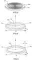
- FIG. 1a depicts a first exemplary antenna system in one set of embodiments of the invention.
- the antenna system Sys1a comprises a ground plane with a cylindrical cavity Cav filled with a dielectric, magnetic or magneto-dielectric substrate.
- the cavity includes an opening and walls.
- the antenna system Sys1a also includes an antenna Ant arranged on the dielectric, magnetic or magneto-dielectric substrate.
- the invention will be described through examples where the antenna is a planar antenna, but the invention is not restricted to these examples, and 3D antennas could be used.
- the substrate is a so-called low-loss dielectric substrate, for example a substrate whose dielectric loss angle tangent (tan ⁇ ) is less than 10 ⁇ 2 .
- This substrate can also be either magnetic or magneto-dielectric.
- the cavity may also be filled with electromagnetic absorber and/or a partial resistive film may be placed therein.
- the Ant antenna can be of different types, for example a planar antenna.
- the planar antenna Ant can be a spiral antenna, a sinuous antenna or a planar periodic antenna. It can for example be formed of different current rings corresponding to different frequencies, the perimeter of a given ring being equal to the wavelength of the corresponding frequency. The outer rings therefore correspond to low frequencies, and the inner rings to high frequencies.
- This type of spiral therefore makes it possible to operate the antenna over a wide band of frequencies, within which the different rings contribute to the radiation for different frequencies according to their diameter (for a wavelength ⁇ , it is a ring-shaped zone of circumference ⁇ which will contribute to the radiation).
- the Ant antenna can be a transmit or receive antenna.
- FIG. 2 shows an example of a spiral antenna in one set of embodiments of the invention.
- FIG. 2 shows an example of such a spiral antenna comprising two strands Brin1 and Brin2, said antenna being printed on the dielectric substrate Subs of thickness h1 and diameter d1.
- the X, Y and Z axes represent three axes of an orthogonal frame, where Z is the axis of the antenna.
- the X and Y axes correspond to the plane of the antenna, and can be defined for example by the geometry of the points of excitation of the spiral.
- these same three axes X, Y and Z will be represented in several figures.
- the “top” of the system will correspond to high values on the z axis, and the “bottom” to low values.
- an element will be considered “on” or “above” another if its position is higher on the z axis, and on the contrary "under” or “below” another if its position is weaker on the z axis.
- the so-called reference section comprises a metallic cavity Cav, on which is arranged the dielectric substrate Subs in which the planar antenna Ant is printed.
- the antenna can operate at different frequencies, and, at a given frequency, it is a specific zone of the antenna which will participate in the radiation. For example, in a spiral antenna, for a wavelength ⁇ , it is a zone in the form of a ring of circumference ⁇ which will contribute to the radiation.
- the Sys1a antenna system also includes an absorbing peripheral ring, not visible on the picture 3 , arranged between the antenna and the walls of the cavity.
- the absorbing peripheral crown makes it possible to trap the effects of ends of strands, that is to say to limit the effect of open circuit. Indeed, these effects, by recombining locally with the rest of the circuit radiating towards the center of the antenna, can in particular cause mismatching and a loss of radiation efficiency depending on the frequency.
- the antenna system Sys1a also comprises an absorbing half-lens Lent1a having the shape of an angular sector and comprising a base element substantially covering a first part of the opening of the cavity, a second part of the opening of the cavity not being covered by said base element.
- the first portion of the cavity opening is half of the cavity opening.
- the electromagnetic waves emitted by the antenna will be affected, in the half of the cavity covered by the half-lens, by a phase shift, whereas they will not be modified in the half not covered by the half-lens. .
- peripheral absorbent crown and the absorbent half-lens can be integral, and form a single absorbent element, or be formed from two distinct elements.
- the peripheral absorbent crown, and the absorbent half-lens can be made of a partially absorbent dielectric material.
- an absorbent material comprising carbon can be used.
- This type of material has the advantage of having absorbent properties while being compatible with 3D printing, which makes the antenna system more flexible to reproduce and modify.
- the half-lens can be secured to the cavity Cav and to the antenna Ant, in which case the system Sys1a is formed from a single device.
- the half-lens can on the contrary be located in a device independent of that of the antenna.
- the half-lens can be arranged slightly above the antenna. This makes it possible to integrate the half-lens into already existing antenna devices.
- the half-lens can be integrated into a radome which is added above a pre-existing antenna.
- FIG. 4 shows an example of a metal cavity in one set of embodiments of the invention.
- the cavity Cav is cylindrical in shape, with a diameter d1 and a height h2.
- the metallic cavity has a bottom 410 and metallic walls 420.
- the cavity can be square.
- the ground plane of the cavity may or may not be flat. In the latter case, the depth of the cavity may be lower towards the center thereof.
- the cavity may be conical in shape.
- FIG. 5 shows an example of an absorbent peripheral crown in one set of embodiments of the invention.
- the peripheral absorbent crown Cour is in the form of a hollow cylinder.
- the hollow cylinder has a height h2, and an external diameter d1 respectively identical to the height and external diameter of the metal cavity Cav represented in figure 4 , and a thickness w1, corresponding to an inside diameter d1 - w1.
- the peripheral absorbent crown shown in figure 5 can therefore be placed in the metal cavity shown in figure 4 , and absorb the electromagnetic waves between the antenna and the side 420 of the metal cavity.
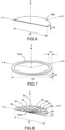
- FIG. 6 shows an example of a basic element of an absorbent half-lens in a set of embodiments of the invention.
- the bottom base element of the absorbing half-lens appears here as a half-cylinder of thickness h4 and diameter d2 > d1.
- the base element can therefore block off half of the metal cavity.
- the base element thus contributes to the deflection of the beam.
- the base element can, in certain embodiments, serve as a support for other elements of the lens such as those represented in figure 8
- the base element is the only element of the half-lens closing off the metal cavity.
- the height of the base element can be set according to the desired deflection of the beam. In particular, certain heights can favor the deflection of the beam in certain frequency bands; the height h4 can therefore be defined as a function of a frequency band to be deflected preferentially.
- FIG. 7 shows an example of an annular element in a set of embodiments of the invention.
- the absorbent half-lens is arranged on an annular element forming an extension of the absorbent peripheral ring out of the cavity as far as the base element.
- the absorbing half-lens and the annular element can be integral and form a single element, or be two distinct juxtaposed elements.
- the annular element Ann is presented as a hollow cylinder of external diameter d1, of thickness w1 and of height h3. It is therefore a hollow half-cylinder of the same external diameter and thickness as the hollow half-cylinder of the peripheral ring shown in figure 5 , which extends it out of the metal cavity, up to the bottom base element, and therefore form a support for the bottom base element.
- This annular element therefore absorbs the reflections of the antenna, while fixing the other elements of the lens and maintaining a fixed distance between the antenna and the base element of the half-lens.
- the half-lens and the annular element are joined, this also makes it possible to produce the half-lens without requiring a mechanical interface between its lower face and the upper face of the radiating circuit.
- the one-piece combination of the half-lens and the annular element, these two elements makes it possible to reduce the assembly interfaces along the axis perpendicular to the radiating circuit, while making it possible to choose precisely the air gap between the upper face of the radiating circuit and the lower face of the half-lens: there is for example no need for a film of glue-foam-film of glue between the radiating circuit and the half-lens .
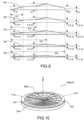
- FIG 8 shows an example of a set of circular sector elements of an absorber half-lens in a set of embodiments of the invention.
- the absorbing half-lens comprises at least one circular sector element whose thickness varies according to the distance from the center of the half-lens.
- the antenna can process, whether it is a transmitting or receiving antenna, frequencies depending on the distance to the center of the antenna, and therefore to the center of the half-lens .
- a spiral, sinuous or log-periodic antenna for which the active zone at a given wavelength has the shape of a ring whose diameter corresponds to the given wavelength, the lower rings therefore corresponding to low frequencies, and the inner rings at high frequencies.
- the thickness of the lens makes it possible to deflect the beam more or less according to the frequencies of the electromagnetic waves.
- Adapting the thickness of the half-lens as a function of the distance from the center therefore makes it possible to locally adapt the deviation of the beam to the frequency of the waves emitted at a given distance from the center of the antenna. This makes it possible to obtain a deflection of the beam which is coherent over a wide frequency band.
- the half-lens comprises a plurality of circular sector elements whose thickness is defined by an increasing function of an angular distance from the edges of the lens.
- Each circular sector element is defined by a thickness profile depending on the distance to the center of the half-lens, and the thickness is defined by an increasing function of an angular distance from the edges of the lens (the angular distance being by example represented by the angle ⁇ starting from the right edge of the half-lens), that is to say that, in the example of the figure 8 , at a given distance from the center, the thickness of the element 8a will be greater than the thicknesses of the elements 8b, themselves greater than the thicknesses of the elements 8c, themselves greater than the thicknesses of the elements 8d, themselves greater than the thicknesses 8th elements.
- FIG. 9 shows an example of a side view of a set of circular sector elements of an absorbing half-lens in a set of embodiments of the invention.
- figure 9 more precisely represents a profile view of the circular sector elements (or sectors) 8a, 8b, 8c, 8d and 8e represented in figure 8 .
- the figure 9 represents the thickness of the profile as a function of the distance from the center of the half-lens, the distance being represented increasing from left to right.
- each circular sector element is defined by a function of increasing then decreasing thickness as a function of a distance from the center of the half-lens.
- the distance ds3 can for example correspond substantially to the radius of the antenna. This makes it possible to obtain a thickness of the half-lens increasing with the distance to the center of the antenna, and therefore with the wavelength of the waves used locally by the antenna. This makes it possible to have a significant thickness for the low frequencies, and weaker for the high frequencies. This makes it possible to obtain a homogeneous beam deflection over a wide frequency band.
- FIG 10 depicts an exemplary overview of an antenna system comprising a set of circular sector elements of an absorber half lens in one set of embodiments of the invention.
- the base element of the half-lens is located either the plurality of circular sector elements Sect, and the absorbing peripheral crown inside the walls of the metal cavity.
- There picture 11a represents an example of radiation patterns of an antenna of the state of the art according to different frequencies, without deflection of the beam of the antenna.
- FIG. 11b shows an example of radiation patterns of an antenna according to different frequencies, with deflection of the beam of the antenna by an antenna system in a set of embodiments of the invention.
- the figures 11a to 18 correspond to 3D electromagnetic simulations performed on an antenna system model according to the invention. They are given by way of illustrative and non-limiting example only of the results obtained by an antenna system according to the invention, different results obtainable in other embodiments of the invention (for example, with another type of antenna, or other dimensions).
- Each of the 6 diagrams represented on the figure 11a And 11b corresponds to a given frequency, from left to right and from top to bottom, 3.5 GHz, 4.5 GHz, 5.5 GHz, 6.5 GHz, 7.5 GHz, and 8.5 GHz.
- the picture 11a represents the diagram without deviation, and the figure 11b the diagram with deviation.
- the deviation is represented by the angle of roll ⁇ and elevation ⁇ .
- FIG 12 shows two sections of a 3D representation of the main lobe of the radiation pattern of an antenna deflected by an antenna system in one set of embodiments of the invention.
- the two cuts correspond to cuts according to the planes defined by the axes X and Y, and the axes X and Z respectively.
- This example shows that the system according to the invention makes it possible to deflect the antenna beam, both according to the roll angle ⁇ and the elevation angle ⁇ .
- FIG 13 shows an example of a deflection angle obtained by an antenna system as a function of frequency in one set of embodiments of the invention.
- FIG 14 shows an example of an angular deviation angle obtained by an antenna system as a function of frequency in one set of embodiments of the invention.
- the angle of angular deviation is between 340° and 25°, and can therefore be limited over the entire frequency band.
- FIG. 15 shows an example of antenna gain achieved by an antenna system as a function of frequency in one set of embodiments of the invention.
- Antenna gain is plotted on the vertical axis, in dB, as a function of frequency, on the horizontal axis, in GHz.
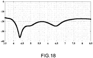
- FIG 16 shows an example of an axial ratio obtained by an antenna system as a function of frequency in one set of embodiments of the invention.
- the axial ratio is represented on the vertical axis, in dB, as a function of frequency, on the horizontal axis, in GHz.
- the axial ratio is well below -3dB, which represents good purity of the polarization, over a wide band of frequencies, in this case all the frequencies tested between 3.5 and 8.5 GHz.
- FIG 17 shows an example of -3dB lobewidth obtained by an antenna system as a function of frequency in one set of embodiments of the invention.
- Lobewidth is plotted on the vertical axis, in dB, as a function of frequency, on the horizontal axis, in GHz.
Landscapes
- Aerials With Secondary Devices (AREA)
Applications Claiming Priority (1)
| Application Number | Priority Date | Filing Date | Title |
|---|---|---|---|
| FR2109426A FR3126818B1 (fr) | 2021-09-09 | 2021-09-09 | Système électromagnétique avec déviation angulaire du lobe principal de rayonnement d'une antenne |
Publications (2)
| Publication Number | Publication Date |
|---|---|
| EP4148902A1 true EP4148902A1 (de) | 2023-03-15 |
| EP4148902B1 EP4148902B1 (de) | 2025-11-26 |
Family
ID=79602080
Family Applications (1)
| Application Number | Title | Priority Date | Filing Date |
|---|---|---|---|
| EP22193180.1A Active EP4148902B1 (de) | 2021-09-09 | 2022-08-31 | Elektromagnetisches system mit winkelabweichung der hauptkeule einer antenne |
Country Status (2)
| Country | Link |
|---|---|
| EP (1) | EP4148902B1 (de) |
| FR (1) | FR3126818B1 (de) |
Cited By (1)
| Publication number | Priority date | Publication date | Assignee | Title |
|---|---|---|---|---|
| US20240243483A1 (en) * | 2023-01-13 | 2024-07-18 | Thales | Antenna system comprising an antenna and a passive device for angular deflection of a main radiation lobe of the antenna. |
Citations (4)
| Publication number | Priority date | Publication date | Assignee | Title |
|---|---|---|---|---|
| US5162806A (en) * | 1990-02-05 | 1992-11-10 | Raytheon Company | Planar antenna with lens for controlling beam widths from two portions thereof at different frequencies |
| US6947010B2 (en) | 2002-12-13 | 2005-09-20 | Broadcom Corporation | Eccentric spiral antenna |
| US20100328779A1 (en) * | 2009-06-30 | 2010-12-30 | California Institute Of Technolology | Dielectric covered planar antennas |
| JP2012205144A (ja) * | 2011-03-25 | 2012-10-22 | Toshiba Denpa Products Kk | スパイラルアンテナ |
Family Cites Families (1)
| Publication number | Priority date | Publication date | Assignee | Title |
|---|---|---|---|---|
| JP2011211420A (ja) * | 2010-03-29 | 2011-10-20 | Toshiba Corp | スパイラルアンテナ |
-
2021
- 2021-09-09 FR FR2109426A patent/FR3126818B1/fr active Active
-
2022
- 2022-08-31 EP EP22193180.1A patent/EP4148902B1/de active Active
Patent Citations (4)
| Publication number | Priority date | Publication date | Assignee | Title |
|---|---|---|---|---|
| US5162806A (en) * | 1990-02-05 | 1992-11-10 | Raytheon Company | Planar antenna with lens for controlling beam widths from two portions thereof at different frequencies |
| US6947010B2 (en) | 2002-12-13 | 2005-09-20 | Broadcom Corporation | Eccentric spiral antenna |
| US20100328779A1 (en) * | 2009-06-30 | 2010-12-30 | California Institute Of Technolology | Dielectric covered planar antennas |
| JP2012205144A (ja) * | 2011-03-25 | 2012-10-22 | Toshiba Denpa Products Kk | スパイラルアンテナ |
Non-Patent Citations (3)
| Title |
|---|
| H. NAKANOT. ABEJ. YAMAUCHI: "A Metaspiral Antenna for Azimuthal Beam Steering", 2019 INTERNATIONAL SYMPOSIUM ON ANTENNAS AND PROPAGATION (ISAP), XI'AN, CHINA, 2019, pages 1 - 3, XP033692238 |
| P. DEOA. MEHTAD. MIRSHEKAR-SYAHKALH. NAKANO: "An HIS-Based Spiral Antenna for Pattern Reconfigurable Applications", IEEE ANTENNAS AND WIRELESS PROPAGATION LETTERS, vol. 8, 2009, pages 196 - 199 |
| TOMOKI ABEJUNJI YAMAUCHIHISAMATSU NAKANO: "Steering of the Circularly Polarized Beam from a Spiral Antenna", IEICE COMMUNICATIONS EXPRESS, 20 February 2020 (2020-02-20) |
Cited By (2)
| Publication number | Priority date | Publication date | Assignee | Title |
|---|---|---|---|---|
| US20240243483A1 (en) * | 2023-01-13 | 2024-07-18 | Thales | Antenna system comprising an antenna and a passive device for angular deflection of a main radiation lobe of the antenna. |
| US12463346B2 (en) * | 2023-01-13 | 2025-11-04 | Thales | Antenna system comprising an antenna and a passive device for angular deflection of a main radiation lobe of the antenna |
Also Published As
| Publication number | Publication date |
|---|---|
| FR3126818A1 (fr) | 2023-03-10 |
| FR3126818B1 (fr) | 2024-02-23 |
| EP4148902B1 (de) | 2025-11-26 |
Similar Documents
| Publication | Publication Date | Title |
|---|---|---|
| EP3547450B1 (de) | Strahlungselement mit kreispolarisierung, bei dem eine resonanz in einem fabry-perot-interferometer angewandt wird | |
| EP0899814B1 (de) | Strahlende Struktur | |
| EP0667984B1 (de) | Monopolantenne mit platten- und stabstrahlern | |
| EP1979987B1 (de) | Antenne mit zirkularer oder linearer polarisation | |
| EP3844844A1 (de) | Antenne zum senden und/oder empfangen einer elektromagnetischen welle und system mit dieser antenne | |
| EP2658032B1 (de) | Hornstrahler einer Antenne mit gewelltem Gitter | |
| EP4148902B1 (de) | Elektromagnetisches system mit winkelabweichung der hauptkeule einer antenne | |
| CA2044903C (fr) | Antenne a balayage par variation de frequence | |
| EP2610966B1 (de) | Kompakte Breitbandantenne von sehr geringer Dicke und mit doppelten orthogonalen linearen Polarisierungen, die für den V/UHF-Bandbereich konzipiert ist | |
| EP0014605B1 (de) | Umgekehrte Cassegrain-Antenne für Mehrzweckradar | |
| EP2817850B1 (de) | Elektromagnetische bandlückenvorrichtung, verwendung davon in einer antennenvorrichtung und parameterfestlegungsverfahren für die antennenvorrichtung | |
| WO2008037887A2 (fr) | Antenne a materiau bip (bande interdite photonique) systeme | |
| FR2945674A1 (fr) | Dispositif de depointage du faisceau d'une antenne a balayage de faisceau utilisant le dispositif | |
| EP4199258A1 (de) | Elementare mikrostreifenantenne und verbesserte gruppenantenne | |
| EP3218961A1 (de) | Rekonfigurierbare kompakte antennenvorrichtung | |
| EP4270642B1 (de) | Verbesserte hornantenne | |
| EP3902059A1 (de) | Breitband-richtantenne mit longitudinalwellen-übertragung | |
| FR3154872A1 (fr) | Dispositif d'émission / réception à domaine de dépointage étendu | |
| FR3114195A1 (fr) | Antenne à couverture améliorée sur un domaine de fréquence élargi | |
| EP4383458B1 (de) | Verbessertes antennensystem und entkopplungsvorrichtung dafür | |
| EP4401239A1 (de) | Antennensystem mit einer antenne und einer passiven vorrichtung zur winkelabweichung einer antennen-hauptkeule | |
| CA2800949C (fr) | Antenne compacte a large bande a double polarisation lineaire | |
| EP4572014A1 (de) | Rundstrahlantenne und antennenanordnung dafür. | |
| EP4391232A1 (de) | Weitwinkel-impedanzanpassungsvorrichtung für eine gruppenantenne mit strahlungselementen und verfahren zum entwurf einer solchen vorrichtung | |
| FR2803694A1 (fr) | Antenne a cavite resonante ayant un faisceau conforme selon un diagramme de rayonnement predetermine |
Legal Events
| Date | Code | Title | Description |
|---|---|---|---|
| PUAI | Public reference made under article 153(3) epc to a published international application that has entered the european phase |
Free format text: ORIGINAL CODE: 0009012 |
|
| STAA | Information on the status of an ep patent application or granted ep patent |
Free format text: STATUS: THE APPLICATION HAS BEEN PUBLISHED |
|
| AK | Designated contracting states |
Kind code of ref document: A1 Designated state(s): AL AT BE BG CH CY CZ DE DK EE ES FI FR GB GR HR HU IE IS IT LI LT LU LV MC MK MT NL NO PL PT RO RS SE SI SK SM TR |
|
| STAA | Information on the status of an ep patent application or granted ep patent |
Free format text: STATUS: REQUEST FOR EXAMINATION WAS MADE |
|
| 17P | Request for examination filed |
Effective date: 20230420 |
|
| RBV | Designated contracting states (corrected) |
Designated state(s): AL AT BE BG CH CY CZ DE DK EE ES FI FR GB GR HR HU IE IS IT LI LT LU LV MC MK MT NL NO PL PT RO RS SE SI SK SM TR |
|
| GRAP | Despatch of communication of intention to grant a patent |
Free format text: ORIGINAL CODE: EPIDOSNIGR1 |
|
| STAA | Information on the status of an ep patent application or granted ep patent |
Free format text: STATUS: GRANT OF PATENT IS INTENDED |
|
| INTG | Intention to grant announced |
Effective date: 20250721 |
|
| GRAS | Grant fee paid |
Free format text: ORIGINAL CODE: EPIDOSNIGR3 |
|
| GRAA | (expected) grant |
Free format text: ORIGINAL CODE: 0009210 |
|
| STAA | Information on the status of an ep patent application or granted ep patent |
Free format text: STATUS: THE PATENT HAS BEEN GRANTED |
|
| AK | Designated contracting states |
Kind code of ref document: B1 Designated state(s): AL AT BE BG CH CY CZ DE DK EE ES FI FR GB GR HR HU IE IS IT LI LT LU LV MC MK MT NL NO PL PT RO RS SE SI SK SM TR |
|
| RAP3 | Party data changed (applicant data changed or rights of an application transferred) |
Owner name: THALES Owner name: INDIAN INSTITUTE OF SCIENCE Owner name: UNIVERSITE DE BRETAGNE OCCIDENTALE Owner name: CENTRE NATIONAL DE LA RECHERCHE SCIENTIFIQUE |
|
| REG | Reference to a national code |
Ref country code: CH Ref legal event code: F10 Free format text: ST27 STATUS EVENT CODE: U-0-0-F10-F00 (AS PROVIDED BY THE NATIONAL OFFICE) Effective date: 20251126 Ref country code: GB Ref legal event code: FG4D Free format text: NOT ENGLISH |
|
| P01 | Opt-out of the competence of the unified patent court (upc) registered |
Free format text: CASE NUMBER: UPC_APP_0010893_4148902/2025 Effective date: 20251023 |
|
| REG | Reference to a national code |
Ref country code: IE Ref legal event code: FG4D Free format text: LANGUAGE OF EP DOCUMENT: FRENCH |
|
| REG | Reference to a national code |
Ref country code: DE Ref legal event code: R096 Ref document number: 602022025519 Country of ref document: DE |
|
| REG | Reference to a national code |
Ref country code: SE Ref legal event code: TRGR |