EP4148902A1 - Electromagnetic system with angular deviation of the main dispersion lobe of an antenna. - Google Patents
Electromagnetic system with angular deviation of the main dispersion lobe of an antenna. Download PDFInfo
- Publication number
- EP4148902A1 EP4148902A1 EP22193180.1A EP22193180A EP4148902A1 EP 4148902 A1 EP4148902 A1 EP 4148902A1 EP 22193180 A EP22193180 A EP 22193180A EP 4148902 A1 EP4148902 A1 EP 4148902A1
- Authority
- EP
- European Patent Office
- Prior art keywords
- antenna
- lens
- cavity
- absorbing
- antenna system
- Prior art date
- Legal status (The legal status is an assumption and is not a legal conclusion. Google has not performed a legal analysis and makes no representation as to the accuracy of the status listed.)
- Pending
Links
Images


Classifications
-
- H—ELECTRICITY
- H01—ELECTRIC ELEMENTS
- H01Q—ANTENNAS, i.e. RADIO AERIALS
- H01Q1/00—Details of, or arrangements associated with, antennas
- H01Q1/36—Structural form of radiating elements, e.g. cone, spiral, umbrella; Particular materials used therewith
-
- H—ELECTRICITY
- H01—ELECTRIC ELEMENTS
- H01Q—ANTENNAS, i.e. RADIO AERIALS
- H01Q17/00—Devices for absorbing waves radiated from an antenna; Combinations of such devices with active antenna elements or systems
-
- H—ELECTRICITY
- H01—ELECTRIC ELEMENTS
- H01Q—ANTENNAS, i.e. RADIO AERIALS
- H01Q17/00—Devices for absorbing waves radiated from an antenna; Combinations of such devices with active antenna elements or systems
- H01Q17/001—Devices for absorbing waves radiated from an antenna; Combinations of such devices with active antenna elements or systems for modifying the directional characteristic of an aerial
-
- H—ELECTRICITY
- H01—ELECTRIC ELEMENTS
- H01Q—ANTENNAS, i.e. RADIO AERIALS
- H01Q19/00—Combinations of primary active antenna elements and units with secondary devices, e.g. with quasi-optical devices, for giving the antenna a desired directional characteristic
- H01Q19/06—Combinations of primary active antenna elements and units with secondary devices, e.g. with quasi-optical devices, for giving the antenna a desired directional characteristic using refracting or diffracting devices, e.g. lens
-
- H—ELECTRICITY
- H01—ELECTRIC ELEMENTS
- H01Q—ANTENNAS, i.e. RADIO AERIALS
- H01Q9/00—Electrically-short antennas having dimensions not more than twice the operating wavelength and consisting of conductive active radiating elements
- H01Q9/04—Resonant antennas
- H01Q9/16—Resonant antennas with feed intermediate between the extremities of the antenna, e.g. centre-fed dipole
- H01Q9/26—Resonant antennas with feed intermediate between the extremities of the antenna, e.g. centre-fed dipole with folded element or elements, the folded parts being spaced apart a small fraction of operating wavelength
- H01Q9/27—Spiral antennas
Definitions
- the present invention relates to the field of antennas. More specifically, it relates to the control of the radiation pattern, and in particular of the angular direction of the main antenna radiation lobe.
- an antenna In an airborne and/or naval system, electromagnetic communication is the dominant mode of communication due to its accuracy, ease of control, and wide range of functionality.
- An antenna is an essential part of a wireless system.
- an antenna For communications purposes, an antenna is ideally a broadband and circularly polarized or dual linearly polarized antenna.
- an antenna system must be as compact as possible.
- one of the possible solutions consists in placing the antenna in a compact cavity.
- the cavity makes the radiation unidirectional and provides the antenna with electromagnetic shielding vis-à-vis the surrounding electronic systems.
- a possible structure consists of placing a spiral antenna on a filled cavity of an electromagnetic absorber.
- Such an antenna has a unidirectional radiation pattern, in the direction of the line of sight, that is to say along the radioelectric axis of the antenna.
- the main beam or lobe of radiation from the antenna should be aimed slightly forward (for example) rather than directly towards the ground, i.e. i.e. it should face forward at an angle to the perpendicular to the floor.
- Another objective of this angular deviation is to avoid interference between the various antennas of the aircraft, including between an antenna in transmission and an antenna in reception.
- antennas with a wide frequency band usually have fairly wide radiation lobes, which can lead to undesirable interactions between nearby antennas.
- the antenna In the context of a spiral antenna system loaded with an electromagnetic absorber placed in the antenna cavity (the antenna cavity representing the part between the lower part of the substrate of the radiating circuit and the lower reflective plane (or ground plane)), the antenna is physically tilted to meet this requirement. This physical tilt, however, may not be possible in the design of the aircraft on which the antenna is to be placed.
- the use of an antenna array is another possible solution but it is not suitable in an environment where space is a strong constraint.
- Another solution consists in applying an angular deviation to the beam.
- the electronic deviation consists in inducing a deviation of the main beam with respect to the radioelectric axis of the antenna.
- an electronic deflection In order to be able to operate over a wide band of frequencies, such an electronic deflection must be coherent over a wide frequency range, maintaining good matching, polarization purity and no degradation of radiated gain in the desired direction, so that the antenna can be qualified as a wide frequency band antenna.
- none of the prior art systems is capable of applying beam deflection, nor of modifying the main lobe of the radiation pattern of a wired broadband antenna over a wide band of frequencies.
- the subject of the invention is an antenna system comprising: a ground plane with a cavity covered with a dielectric, magnetic or magneto-dielectric substrate, the cavity comprising an opening and walls; an antenna disposed on the dielectric, magnetic or magneto-dielectric substrate; an absorbent peripheral ring placed between the antenna and the walls; an absorbing half-lens having a shape of an angular sector (or angular segment), comprising a base element substantially covering a first part of the opening of the cavity, a second part of the opening of the cavity being not covered by said basic element.
- the absorbent half-lens comprises an annular element forming an extension of the absorbent peripheral ring on the second part of the opening.
- the first part of the opening of the cavity corresponds to half of the opening of the cavity
- the absorbing half-lens comprises at least one circular sector element whose thickness varies according to the distance from the center of the half-lens.
- the absorbing half-lens comprises a plurality of circular sector elements whose thickness is defined by an increasing function of an angular distance from the edges of the lens.
- each circular sector element is defined by a function of increasing then decreasing thickness as a function of a distance from the center of the half-lens.
- At least one element among the absorbent peripheral ring and the half-lens is made of a partially absorbent dielectric material.
- the dielectric material partially comprises carbon.
- the antenna is a spiral antenna, a sinusoidal antenna or a periodic antenna.
- the antenna is one defined by an Archimedean spiral.
- the antenna is a broadband antenna, making it possible to obtain a substantially constant deviation angle over the entire operating frequency band of the antenna.
- the antenna system comprises: a first device comprising the ground plane, the antenna and the peripheral absorbing ring; a second device comprising the absorbing half-lens.
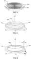
- FIG. 1a depicts a first exemplary antenna system in one set of embodiments of the invention.
- the antenna system Sys1a comprises a ground plane with a cylindrical cavity Cav filled with a dielectric, magnetic or magneto-dielectric substrate.
- the cavity includes an opening and walls.
- the antenna system Sys1a also includes an antenna Ant arranged on the dielectric, magnetic or magneto-dielectric substrate.
- the invention will be described through examples where the antenna is a planar antenna, but the invention is not restricted to these examples, and 3D antennas could be used.
- the substrate is a so-called low-loss dielectric substrate, for example a substrate whose dielectric loss angle tangent (tan ⁇ ) is less than 10 ⁇ 2 .
- This substrate can also be either magnetic or magneto-dielectric.
- the cavity may also be filled with electromagnetic absorber and/or a partial resistive film may be placed therein.
- the Ant antenna can be of different types, for example a planar antenna.
- the planar antenna Ant can be a spiral antenna, a sinuous antenna or a planar periodic antenna. It can for example be formed of different current rings corresponding to different frequencies, the perimeter of a given ring being equal to the wavelength of the corresponding frequency. The outer rings therefore correspond to low frequencies, and the inner rings to high frequencies.
- This type of spiral therefore makes it possible to operate the antenna over a wide band of frequencies, within which the different rings contribute to the radiation for different frequencies according to their diameter (for a wavelength ⁇ , it is a ring-shaped zone of circumference ⁇ which will contribute to the radiation).
- the Ant antenna can be a transmit or receive antenna.
- FIG. 2 shows an example of a spiral antenna in one set of embodiments of the invention.
- FIG. 2 shows an example of such a spiral antenna comprising two strands Brin1 and Brin2, said antenna being printed on the dielectric substrate Subs of thickness h1 and diameter d1.
- the X, Y and Z axes represent three axes of an orthogonal frame, where Z is the axis of the antenna.
- the X and Y axes correspond to the plane of the antenna, and can be defined for example by the geometry of the points of excitation of the spiral.
- these same three axes X, Y and Z will be represented in several figures.
- the “top” of the system will correspond to high values on the z axis, and the “bottom” to low values.
- an element will be considered “on” or “above” another if its position is higher on the z axis, and on the contrary "under” or “below” another if its position is weaker on the z axis.
- the so-called reference section comprises a metallic cavity Cav, on which is arranged the dielectric substrate Subs in which the planar antenna Ant is printed.
- the antenna can operate at different frequencies, and, at a given frequency, it is a specific zone of the antenna which will participate in the radiation. For example, in a spiral antenna, for a wavelength ⁇ , it is a zone in the form of a ring of circumference ⁇ which will contribute to the radiation.
- the Sys1a antenna system also includes an absorbing peripheral ring, not visible on the picture 3 , arranged between the antenna and the walls of the cavity.
- the absorbing peripheral crown makes it possible to trap the effects of ends of strands, that is to say to limit the effect of open circuit. Indeed, these effects, by recombining locally with the rest of the circuit radiating towards the center of the antenna, can in particular cause mismatching and a loss of radiation efficiency depending on the frequency.
- the antenna system Sys1a also comprises an absorbing half-lens Lent1a having the shape of an angular sector and comprising a base element substantially covering a first part of the opening of the cavity, a second part of the opening of the cavity not being covered by said base element.
- the first portion of the cavity opening is half of the cavity opening.
- the electromagnetic waves emitted by the antenna will be affected, in the half of the cavity covered by the half-lens, by a phase shift, whereas they will not be modified in the half not covered by the half-lens. .
- peripheral absorbent crown and the absorbent half-lens can be integral, and form a single absorbent element, or be formed from two distinct elements.
- the peripheral absorbent crown, and the absorbent half-lens can be made of a partially absorbent dielectric material.
- an absorbent material comprising carbon can be used.
- This type of material has the advantage of having absorbent properties while being compatible with 3D printing, which makes the antenna system more flexible to reproduce and modify.
- the half-lens can be secured to the cavity Cav and to the antenna Ant, in which case the system Sys1a is formed from a single device.
- the half-lens can on the contrary be located in a device independent of that of the antenna.
- the half-lens can be arranged slightly above the antenna. This makes it possible to integrate the half-lens into already existing antenna devices.
- the half-lens can be integrated into a radome which is added above a pre-existing antenna.
- FIG. 4 shows an example of a metal cavity in one set of embodiments of the invention.
- the cavity Cav is cylindrical in shape, with a diameter d1 and a height h2.
- the metallic cavity has a bottom 410 and metallic walls 420.
- the cavity can be square.
- the ground plane of the cavity may or may not be flat. In the latter case, the depth of the cavity may be lower towards the center thereof.
- the cavity may be conical in shape.
- FIG. 5 shows an example of an absorbent peripheral crown in one set of embodiments of the invention.
- the peripheral absorbent crown Cour is in the form of a hollow cylinder.
- the hollow cylinder has a height h2, and an external diameter d1 respectively identical to the height and external diameter of the metal cavity Cav represented in figure 4 , and a thickness w1, corresponding to an inside diameter d1 - w1.
- the peripheral absorbent crown shown in figure 5 can therefore be placed in the metal cavity shown in figure 4 , and absorb the electromagnetic waves between the antenna and the side 420 of the metal cavity.
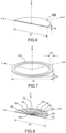
- FIG. 6 shows an example of a basic element of an absorbent half-lens in a set of embodiments of the invention.
- the bottom base element of the absorbing half-lens appears here as a half-cylinder of thickness h4 and diameter d2 > d1.
- the base element can therefore block off half of the metal cavity.
- the base element thus contributes to the deflection of the beam.
- the base element can, in certain embodiments, serve as a support for other elements of the lens such as those represented in figure 8
- the base element is the only element of the half-lens closing off the metal cavity.
- the height of the base element can be set according to the desired deflection of the beam. In particular, certain heights can favor the deflection of the beam in certain frequency bands; the height h4 can therefore be defined as a function of a frequency band to be deflected preferentially.
- FIG. 7 shows an example of an annular element in a set of embodiments of the invention.
- the absorbent half-lens is arranged on an annular element forming an extension of the absorbent peripheral ring out of the cavity as far as the base element.
- the absorbing half-lens and the annular element can be integral and form a single element, or be two distinct juxtaposed elements.
- the annular element Ann is presented as a hollow cylinder of external diameter d1, of thickness w1 and of height h3. It is therefore a hollow half-cylinder of the same external diameter and thickness as the hollow half-cylinder of the peripheral ring shown in figure 5 , which extends it out of the metal cavity, up to the bottom base element, and therefore form a support for the bottom base element.
- This annular element therefore absorbs the reflections of the antenna, while fixing the other elements of the lens and maintaining a fixed distance between the antenna and the base element of the half-lens.
- the half-lens and the annular element are joined, this also makes it possible to produce the half-lens without requiring a mechanical interface between its lower face and the upper face of the radiating circuit.
- the one-piece combination of the half-lens and the annular element, these two elements makes it possible to reduce the assembly interfaces along the axis perpendicular to the radiating circuit, while making it possible to choose precisely the air gap between the upper face of the radiating circuit and the lower face of the half-lens: there is for example no need for a film of glue-foam-film of glue between the radiating circuit and the half-lens .
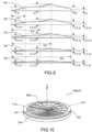
- FIG 8 shows an example of a set of circular sector elements of an absorber half-lens in a set of embodiments of the invention.
- the absorbing half-lens comprises at least one circular sector element whose thickness varies according to the distance from the center of the half-lens.
- the antenna can process, whether it is a transmitting or receiving antenna, frequencies depending on the distance to the center of the antenna, and therefore to the center of the half-lens .
- a spiral, sinuous or log-periodic antenna for which the active zone at a given wavelength has the shape of a ring whose diameter corresponds to the given wavelength, the lower rings therefore corresponding to low frequencies, and the inner rings at high frequencies.
- the thickness of the lens makes it possible to deflect the beam more or less according to the frequencies of the electromagnetic waves.
- Adapting the thickness of the half-lens as a function of the distance from the center therefore makes it possible to locally adapt the deviation of the beam to the frequency of the waves emitted at a given distance from the center of the antenna. This makes it possible to obtain a deflection of the beam which is coherent over a wide frequency band.
- the half-lens comprises a plurality of circular sector elements whose thickness is defined by an increasing function of an angular distance from the edges of the lens.
- Each circular sector element is defined by a thickness profile depending on the distance to the center of the half-lens, and the thickness is defined by an increasing function of an angular distance from the edges of the lens (the angular distance being by example represented by the angle ⁇ starting from the right edge of the half-lens), that is to say that, in the example of the figure 8 , at a given distance from the center, the thickness of the element 8a will be greater than the thicknesses of the elements 8b, themselves greater than the thicknesses of the elements 8c, themselves greater than the thicknesses of the elements 8d, themselves greater than the thicknesses 8th elements.
- FIG. 9 shows an example of a side view of a set of circular sector elements of an absorbing half-lens in a set of embodiments of the invention.
- figure 9 more precisely represents a profile view of the circular sector elements (or sectors) 8a, 8b, 8c, 8d and 8e represented in figure 8 .
- the figure 9 represents the thickness of the profile as a function of the distance from the center of the half-lens, the distance being represented increasing from left to right.
- each circular sector element is defined by a function of increasing then decreasing thickness as a function of a distance from the center of the half-lens.
- the distance ds3 can for example correspond substantially to the radius of the antenna. This makes it possible to obtain a thickness of the half-lens increasing with the distance to the center of the antenna, and therefore with the wavelength of the waves used locally by the antenna. This makes it possible to have a significant thickness for the low frequencies, and weaker for the high frequencies. This makes it possible to obtain a homogeneous beam deflection over a wide frequency band.
- FIG 10 depicts an exemplary overview of an antenna system comprising a set of circular sector elements of an absorber half lens in one set of embodiments of the invention.
- the base element of the half-lens is located either the plurality of circular sector elements Sect, and the absorbing peripheral crown inside the walls of the metal cavity.
- There picture 11a represents an example of radiation patterns of an antenna of the state of the art according to different frequencies, without deflection of the beam of the antenna.
- FIG. 11b shows an example of radiation patterns of an antenna according to different frequencies, with deflection of the beam of the antenna by an antenna system in a set of embodiments of the invention.
- the figures 11a to 18 correspond to 3D electromagnetic simulations performed on an antenna system model according to the invention. They are given by way of illustrative and non-limiting example only of the results obtained by an antenna system according to the invention, different results obtainable in other embodiments of the invention (for example, with another type of antenna, or other dimensions).
- Each of the 6 diagrams represented on the figure 11a And 11b corresponds to a given frequency, from left to right and from top to bottom, 3.5 GHz, 4.5 GHz, 5.5 GHz, 6.5 GHz, 7.5 GHz, and 8.5 GHz.
- the picture 11a represents the diagram without deviation, and the figure 11b the diagram with deviation.
- the deviation is represented by the angle of roll ⁇ and elevation ⁇ .
- FIG 12 shows two sections of a 3D representation of the main lobe of the radiation pattern of an antenna deflected by an antenna system in one set of embodiments of the invention.
- the two cuts correspond to cuts according to the planes defined by the axes X and Y, and the axes X and Z respectively.
- This example shows that the system according to the invention makes it possible to deflect the antenna beam, both according to the roll angle ⁇ and the elevation angle ⁇ .
- FIG 13 shows an example of a deflection angle obtained by an antenna system as a function of frequency in one set of embodiments of the invention.
- FIG 14 shows an example of an angular deviation angle obtained by an antenna system as a function of frequency in one set of embodiments of the invention.
- the angle of angular deviation is between 340° and 25°, and can therefore be limited over the entire frequency band.
- FIG. 15 shows an example of antenna gain achieved by an antenna system as a function of frequency in one set of embodiments of the invention.
- Antenna gain is plotted on the vertical axis, in dB, as a function of frequency, on the horizontal axis, in GHz.
- FIG 16 shows an example of an axial ratio obtained by an antenna system as a function of frequency in one set of embodiments of the invention.
- the axial ratio is represented on the vertical axis, in dB, as a function of frequency, on the horizontal axis, in GHz.
- the axial ratio is well below -3dB, which represents good purity of the polarization, over a wide band of frequencies, in this case all the frequencies tested between 3.5 and 8.5 GHz.
- FIG 17 shows an example of -3dB lobewidth obtained by an antenna system as a function of frequency in one set of embodiments of the invention.
- Lobewidth is plotted on the vertical axis, in dB, as a function of frequency, on the horizontal axis, in GHz.
Abstract
L'invention concerne un système d'antenne comprenant : un plan de masse avec une cavité recouverte d'un substrat diélectrique, magnétique ou magnéto-diélectrique ; une antenne disposée sur la cavité ; une couronne périphérique absorbante disposée entre l'antenne et les parois de la cavité ; une demi-lentille absorbante, comprenant un élément de base couvrant sensiblement la moitié de la cavité

Description
La présente invention concerne le domaine des antennes. Plus spécifiquement, elle concerne le contrôle du diagramme de rayonnement, et en particulier de la direction angulaire du lobe principal de rayonnement d'antennes.The present invention relates to the field of antennas. More specifically, it relates to the control of the radiation pattern, and in particular of the angular direction of the main antenna radiation lobe.
Dans un système aéroporté et/ou naval, la communication électromagnétique est le mode de communication dominant en raison de sa précision, de sa facilité de contrôle et de sa large gamme de fonctionnalités. Une antenne est un élément essentiel d'un système sans fil. A des fins de communications, une antenne est idéalement une antenne large bande et polarisée circulairement ou polarisée linéairement double.In an airborne and/or naval system, electromagnetic communication is the dominant mode of communication due to its accuracy, ease of control, and wide range of functionality. An antenna is an essential part of a wireless system. For communications purposes, an antenna is ideally a broadband and circularly polarized or dual linearly polarized antenna.
En raison de la contrainte d'espace sur les porteurs, un système d'antenne doit être aussi compact que possible. A cet effet, l'une des solutions possibles consiste à placer l'antenne dans une cavité compacte. La cavité rend le rayonnement unidirectionnel et assure à l'antenne un blindage électromagnétique vis-à-vis des systèmes électroniques environnants.Due to the space constraint on the carriers, an antenna system must be as compact as possible. To this end, one of the possible solutions consists in placing the antenna in a compact cavity. The cavity makes the radiation unidirectional and provides the antenna with electromagnetic shielding vis-à-vis the surrounding electronic systems.
Cependant, une cavité compacte peut détériorer le mécanisme de rayonnement naturel de l'antenne, entraînant une mauvaise adaptation, une mauvaise polarisation, des ondulations dans le gain rayonné, etc... Une structure envisageable consiste à disposer une antenne spirale sur une cavité remplie d'un absorbant électromagnétique. Une telle antenne a un diagramme de rayonnement unidirectionnel, dans la direction de la ligne de visée, c'est-à-dire le long de l'axe radioélectrique de l'antenne.However, a compact cavity can deteriorate the natural radiation mechanism of the antenna, leading to poor matching, poor polarization, ripples in the radiated gain, etc. A possible structure consists of placing a spiral antenna on a filled cavity of an electromagnetic absorber. Such an antenna has a unidirectional radiation pattern, in the direction of the line of sight, that is to say along the radioelectric axis of the antenna.
Lorsqu'une antenne placée sous un aéronef volant est orientée vers le sol, le faisceau ou lobe principal de rayonnement de l'antenne doit être orienté légèrement vers l'avant (par exemple) plutôt que directement vers le sol, c'est-à-dire qu'il doit être orienté vers l'avant avec un angle par rapport à la perpendiculaire du sol.When an antenna placed under a flying aircraft is pointed towards the ground, the main beam or lobe of radiation from the antenna should be aimed slightly forward (for example) rather than directly towards the ground, i.e. i.e. it should face forward at an angle to the perpendicular to the floor.
Un autre objectif de cette déviation angulaire est d'éviter les interférences entre les différentes antennes de l'aéronef, y compris entre une antenne en émission et une antenne en réception. En effet, des antennes à large bande de fréquence ont habituellement des lobes de rayonnement assez larges, pouvant entraîner des interactions indésirables entre des antennes proches.Another objective of this angular deviation is to avoid interference between the various antennas of the aircraft, including between an antenna in transmission and an antenna in reception. Indeed, antennas with a wide frequency band usually have fairly wide radiation lobes, which can lead to undesirable interactions between nearby antennas.
Dans le cadre d'un système d'antenne spirale chargé par un absorbant électromagnétique placé dans de la cavité d'antenne (la cavité d'antenne représentant la partie comprise entre la partie inférieure du substrat du circuit rayonnant et le plan réflecteur inférieur (ou plan de masse)), l'antenne est inclinée physiquement pour répondre à cette exigence. Cette inclinaison physique peut cependant ne pas être possible dans la conception de l'aéronef sur lequel l'antenne doit être placée. L'utilisation d'un réseau d'antennes est une autre solution possible mais elle ne convient pas dans un environnement où l'espace est une contrainte forte.In the context of a spiral antenna system loaded with an electromagnetic absorber placed in the antenna cavity (the antenna cavity representing the part between the lower part of the substrate of the radiating circuit and the lower reflective plane (or ground plane)), the antenna is physically tilted to meet this requirement. This physical tilt, however, may not be possible in the design of the aircraft on which the antenna is to be placed. The use of an antenna array is another possible solution but it is not suitable in an environment where space is a strong constraint.
Une autre solution consiste à appliquer une déviation angulaire au faisceau. La déviation électronique consiste à induire une déviation du faisceau principal par rapport à l'axe radioélectrique de l'antenne. Afin de pouvoir fonctionner sur une large bande de fréquences, une telle déviation électronique doit être cohérente sur une large gamme de fréquences, en maintenant une bonne adaptation, la pureté de la polarisation et sans dégradation du gain rayonné dans la direction voulue, afin que l'antenne puisse être qualifiée d'antenne à large bande de fréquences.Another solution consists in applying an angular deviation to the beam. The electronic deviation consists in inducing a deviation of the main beam with respect to the radioelectric axis of the antenna. In order to be able to operate over a wide band of frequencies, such an electronic deflection must be coherent over a wide frequency range, maintaining good matching, polarization purity and no degradation of radiated gain in the desired direction, so that the antenna can be qualified as a wide frequency band antenna.
La problématique de la déviation du faisceau d'une antenne a été partiellement adressée par l'art antérieur.The problem of the deflection of the beam of an antenna has been partially addressed by the prior art.
La demande de brevet américaine publiée sous le numéro
Le papier
Les documents
Cependant, aucun des systèmes de l'art antérieur n'est capable d'appliquer une déviation du faisceau, ni de modifier le lobe principal du diagramme de rayonnement d'une antenne à large bande filaire sur une large bande de fréquences.However, none of the prior art systems is capable of applying beam deflection, nor of modifying the main lobe of the radiation pattern of a wired broadband antenna over a wide band of frequencies.
Il y a donc besoin d'un système d'antenne apte à générer une déviation angulaire du faisceau de l'antenne sur une large bande de fréquence. Il y a également besoin d'un système d'antenne apte à générer une déviation du faisceau de l'antenne tout en limitant son encombrement.There is therefore a need for an antenna system capable of generating an angular deviation of the antenna beam over a wide frequency band. There is also a need for an antenna system capable of generating a deflection of the beam of the antenna while limiting its size.
A cet effet, l'invention a pour objet un système d'antenne comprenant : un plan de masse avec une cavité recouverte d'un substrat diélectrique, magnétique ou magnéto-diélectrique, la cavité comprenant une ouverture et des parois ; une antenne disposée sur le substrat diélectrique, magnétique ou magnéto-diélectrique ; une couronne périphérique absorbante disposée entre l'antenne et les parois; une demi-lentille absorbante ayant une forme d'un secteur angulaire (ou segment angulaire), comprenant un élément de base couvrant sensiblement une première partie de l'ouverture de la cavité, une seconde partie de l'ouverture de la cavité n'étant pas couverte par ledit élément de base.To this end, the subject of the invention is an antenna system comprising: a ground plane with a cavity covered with a dielectric, magnetic or magneto-dielectric substrate, the cavity comprising an opening and walls; an antenna disposed on the dielectric, magnetic or magneto-dielectric substrate; an absorbent peripheral ring placed between the antenna and the walls; an absorbing half-lens having a shape of an angular sector (or angular segment), comprising a base element substantially covering a first part of the opening of the cavity, a second part of the opening of the cavity being not covered by said basic element.
Avantageusement, la demi-lentille absorbante comprend un élément annulaire formant un prolongement de la couronne périphérique absorbante sur la seconde partie de l'ouverture.Advantageously, the absorbent half-lens comprises an annular element forming an extension of the absorbent peripheral ring on the second part of the opening.
Avantageusement, dans lequel la première partie de l'ouverture de la cavité correspond à la moitié de l'ouverture de la cavitéAdvantageously, in which the first part of the opening of the cavity corresponds to half of the opening of the cavity
Avantageusement, la demi-lentille absorbante comprend au moins un élément secteur circulaire dont l'épaisseur varie en fonction de la distance au centre de la demi-lentille.Advantageously, the absorbing half-lens comprises at least one circular sector element whose thickness varies according to the distance from the center of the half-lens.
Avantageusement, la demi-lentille absorbante comprend une pluralité d'éléments secteur circulaire dont l'épaisseur est définie par une fonction croissante d'une distance angulaire des bords de la lentille.Advantageously, the absorbing half-lens comprises a plurality of circular sector elements whose thickness is defined by an increasing function of an angular distance from the edges of the lens.
Avantageusement, chaque élément secteur circulaire est défini par une fonction d'épaisseur croissant puis décroissant en fonction d'une distance au centre de la demi-lentille.Advantageously, each circular sector element is defined by a function of increasing then decreasing thickness as a function of a distance from the center of the half-lens.
Avantageusement, un élément au moins parmi la couronne périphérique absorbante, et de la demi-lentille est faite d'un matériau diélectrique partiellement absorbant.Advantageously, at least one element among the absorbent peripheral ring and the half-lens is made of a partially absorbent dielectric material.
Avantageusement, le matériau diélectrique comprend partiellement du carbone.Advantageously, the dielectric material partially comprises carbon.
Avantageusement, l'antenne est une antenne spirale, une antenne sinusoïde ou une antenne périodique.Advantageously, the antenna is a spiral antenna, a sinusoidal antenna or a periodic antenna.
Avantrageusement, l'antenne est une définie par une spirale d'Archimède.Advantageously, the antenna is one defined by an Archimedean spiral.
Avantageusement, l'antenne est une antenne large bande, permettant d'obtenir un angle de déviation substantiellement constant sur l'ensemble de la bande de fréquence de fonctionnement de l'antenne.Advantageously, the antenna is a broadband antenna, making it possible to obtain a substantially constant deviation angle over the entire operating frequency band of the antenna.
Avantageusement, le système d'antenne comprend : un premier dispositif comprenant le plan de masse, l'antenne et la couronne périphérique absorbante ; un deuxième dispositif comprenant la demi-lentille absorbante.Advantageously, the antenna system comprises: a first device comprising the ground plane, the antenna and the peripheral absorbing ring; a second device comprising the absorbing half-lens.
D'autres caractéristiques, détails et avantages de l'invention ressortiront à la lecture de la description faite en référence aux dessins annexés donnés à titre d'exemple et qui représentent, respectivement :
- [
Fig.1a ] un premier exemple de système d'antenne dans un ensemble de modes de réalisation de l'invention ; - [
Fig.1b ], un deuxième exemple de système d'antenne dans un ensemble de modes de réalisation de l'invention ; - [
Fig.2 ], un exemple d'antenne spirale dans un ensemble de modes de réalisation de l'invention ; - [
Fig.3 ], un exemple de section dite de référence d'un système d'antenne dans un ensemble de modes de réalisation de l'invention ; - [
Fig.4 ], un exemple de cavité métallique dans un ensemble de modes de réalisation de l'invention ; - [
Fig.5 ], un exemple de couronne périphérique absorbante dans un ensemble de modes de réalisation de l'invention ; - [
Fig.6 ], un exemple d'élément de base d'une demi-lentille absorbante dans un ensemble de modes de réalisation de l'invention ; - [
Fig.7 ], un exemple d'élément annulaire dans un ensemble de modes de réalisation de l'invention. - [
Fig.8 ], un exemple d'un ensemble d'éléments secteurs circulaires d'une demi-lentille absorbante dans un ensemble de modes de réalisation de l'invention ; - [
Fig.9 ], un exemple de vue de profil d'un ensemble d'éléments secteurs circulaires d'une demi-lentille absorbante dans un ensemble de modes de réalisation de l'invention ; - [
Fig.10 ], un exemple de vue d'ensemble d'un système d'antenne comprenant un ensemble d'éléments secteurs circulaires d'une demi-lentille absorbante dans un ensemble de modes de réalisation de l'invention. - [
Fig.11a ], un exemple de diagrammes de rayonnement d'une antenne de l'état de l'art selon différentes fréquences, sans déviation du faisceau de l'antenne ; - [
Fig.11b ], un exemple de diagrammes de rayonnement d'une antenne selon différentes fréquences, avec déviation du faisceau de l'antenne par un système d'antenne dans un ensemble de modes de réalisation de l'invention ; - [
Fig.12 ], deux coupes d'une représentation 3D du lobe principal du diagramme de rayonnement d'une antenne dévié par un système d'antenne dans un ensemble de modes de réalisation de l'invention ; - [
Fig.13 ], un exemple d'un angle de déviation obtenu par un système d'antenne en fonction de la fréquence dans un ensemble de modes de réalisation de l'invention ; - [
Fig.14 ], un exemple d'un angle de déviation angulaire obtenu par un système d'antenne en fonction de la fréquence dans un ensemble de modes de réalisation de l'invention ; - [
Fig.15 ], un exemple de gain de l'antenne obtenu par un système d'antenne en fonction de la fréquence dans un ensemble de modes de réalisation de l'invention ; - [
Fig.16 ], un exemple de rapport axial obtenu par un système d'antenne en fonction de la fréquence dans un ensemble de modes de réalisation de l'invention ; - [
Fig.17 ], un exemple de largeur de lobe à -3dB obtenu par un système d'antenne en fonction de la fréquence dans un ensemble de modes de réalisation de l'invention ; - [
Fig.18 ], un exemple d'adaptation d'impédance obtenue par un système d'antenne en fonction de la fréquence dans un ensemble de modes de réalisation de l'invention.
- [
Fig.1a ] a first exemplary antenna system in one set of embodiments of the invention; - [
Fig.1b ], a second exemplary antenna system in one set of embodiments of the invention; - [
Fig.2 ], an example of a spiral antenna in a set of embodiments of the invention; - [
Fig.3 ], an example of a so-called reference section of an antenna system in a set of embodiments of the invention; - [
Fig.4 ], an example of a metal cavity in one set of embodiments of the invention; - [
Fig.5 ], an example of an absorbent peripheral ring in one set of embodiments of the invention; - [
Fig.6 ], an example of a basic element of an absorbent half-lens in a set of embodiments of the invention; - [
Fig.7 ], an example of an annular element in a set of embodiments of the invention. - [
Fig.8 ], an example of a set of circular sector elements of an absorbing half-lens in a set of embodiments of the invention; - [
Fig.9 ], an example of a side view of a set of circular sector elements of an absorbing half-lens in a set of embodiments of the invention; - [
Fig.10 ], an exemplary overview of an antenna system comprising a set of circular sector elements of an absorber half-lens in a set of embodiments of the invention. - [
Fig.11a ], an example of radiation patterns of an antenna of the state of the art according to different frequencies, without deflection of the beam of the antenna; - [
Fig.11b ], an example of radiation patterns of an antenna according to different frequencies, with deflection of the beam of the antenna by an antenna system in a set of embodiments of the invention; - [
Fig.12 ], two sections of a 3D representation of the main lobe of the radiation pattern of an antenna deflected by an antenna system in one set of embodiments of the invention; - [
Fig.13 ], an example of a deviation angle obtained by an antenna system as a function of frequency in a set of embodiments of the invention; - [
Fig.14 ], an example of an angular deviation angle obtained by an antenna system as a function of frequency in a set of embodiments of the invention; - [
Fig.15 ], an example of antenna gain obtained by an antenna system as a function of frequency in one set of embodiments of the invention; - [
Fig.16 ], an example of an axial ratio obtained by an antenna system as a function of frequency in a set of embodiments of the invention; - [
Fig.17 ], an example of -3dB lobe width obtained by an antenna system as a function of frequency in a set of embodiments of the invention; - [
Fig.18 ], an example of impedance matching achieved by an antenna system as a function of frequency in one set of embodiments of the invention.
La
Le système d'antenne Sys1a comprend un plan de masse avec une cavité cylindrique Cav emplie d'un substrat diélectrique, magnétique ou magnéto-diélectrique. La cavité comprend une ouverture et des parois. Le système d'antenne Sys1a comprend également une antenne Ant disposée sur le substrat diélectrique, magnétique ou magnéto-diélectrique.The antenna system Sys1a comprises a ground plane with a cylindrical cavity Cav filled with a dielectric, magnetic or magneto-dielectric substrate. The cavity includes an opening and walls. The antenna system Sys1a also includes an antenna Ant arranged on the dielectric, magnetic or magneto-dielectric substrate.
L'invention sera décrite par le biais d'exemple où l'antenne est une antenne planaire, mais l'invention n'est pas restreinte à ces exemples, et des antennes 3D pourraient être utilisées.The invention will be described through examples where the antenna is a planar antenna, but the invention is not restricted to these examples, and 3D antennas could be used.
Dans un ensemble de modes de réalisation de l'invention, le substrat est un substrat diélectrique dit à faible perte, par exemple un substrat dont la tangente d'angle de perte diélectrique (tanδ) est inférieure à 10-2. Ce substrat peut aussi être soit magnétique, soit magnéto-diélectrique.In one set of embodiments of the invention, the substrate is a so-called low-loss dielectric substrate, for example a substrate whose dielectric loss angle tangent (tanδ) is less than 10 −2 . This substrate can also be either magnetic or magneto-dielectric.
La cavité peut également être emplie d'absorbant électromagnétique et/ou un film résistif partiel peut être placé dans celle-ci.The cavity may also be filled with electromagnetic absorber and/or a partial resistive film may be placed therein.
L'antenne Ant peut être de différents types, par exemple une antenne planaire. Par exemple, l'antenne planaire Ant peut être une antenne spirale, une antenne sinueuse ou une antenne périodique plane. Elle peut par exemple être formée de différents anneaux de courant correspondant à différentes fréquences, le périmètre d'un anneau donné étant égal à la longueur d'onde de la fréquence correspondante. Les anneaux extérieurs correspondant donc à des basses fréquences, et les anneaux intérieurs à de hautes fréquences.The Ant antenna can be of different types, for example a planar antenna. For example, the planar antenna Ant can be a spiral antenna, a sinuous antenna or a planar periodic antenna. It can for example be formed of different current rings corresponding to different frequencies, the perimeter of a given ring being equal to the wavelength of the corresponding frequency. The outer rings therefore correspond to low frequencies, and the inner rings to high frequencies.
Ce type de spirale permet donc de faire fonctionner l'antenne sur une large bande de fréquences, au sein de laquelle les différents anneaux contribuent au rayonnement pour différentes fréquences en fonction de leur diamètre (pour une longueur d'onde λ, c'est une zone en forme d'anneau de circonférence λ qui va contribuer au rayonnement).This type of spiral therefore makes it possible to operate the antenna over a wide band of frequencies, within which the different rings contribute to the radiation for different frequencies according to their diameter (for a wavelength λ, it is a ring-shaped zone of circumference λ which will contribute to the radiation).
L'antenne Ant peut être une antenne en émission ou en réception.The Ant antenna can be a transmit or receive antenna.
La
Dans un ensemble de modes de réalisation de l'invention, l'antenne présente par exemple la forme d'une spirale d'Archimède définie par l'équation r(ϕ) = eaϕ , où r(ϕ) est le rayon de la spirale à un emplacement ϕ, et a est une constante.In one set of embodiments of the invention, the antenna has for example the shape of an Archimedean spiral defined by the equation r ( ϕ ) = e aϕ , where r (ϕ) is the radius of the spiral at a location ϕ , and a is a constant.
La
Les axes X, Y et Z représentent trois axes d'un repère orthogonal, où Z est l'axe de l'antenne. Les axes X et Y correspondent au plan de l'antenne, et peuvent être définis par exemple par la géométrie des points d'excitation de la spirale. Par convention, ces mêmes trois axes X, Y et Z seront représentés sur plusieurs figures. Pour faciliter l'intelligibilité de la description, on considèrera que le « haut » du système correspondra à des valeurs élevées sur l'axe z, et le « bas » à des valeurs faibles. Ainsi, un élément sera considéré « sur » ou « au-dessus » d'un autre si sa position est plus élevée sur l'axe z, et au contraire « sous » ou « en-dessous » d'un autre si sa position est plus faible sur l'axe z.The X, Y and Z axes represent three axes of an orthogonal frame, where Z is the axis of the antenna. The X and Y axes correspond to the plane of the antenna, and can be defined for example by the geometry of the points of excitation of the spiral. By convention, these same three axes X, Y and Z will be represented in several figures. To facilitate the intelligibility of the description, it will be considered that the “top” of the system will correspond to high values on the z axis, and the “bottom” to low values. Thus, an element will be considered "on" or "above" another if its position is higher on the z axis, and on the contrary "under" or "below" another if its position is weaker on the z axis.
La
La section dite de référence comprend une cavité métallique Cav, sur laquelle est disposé le substrat diélectrique Subs dans lequel l'antenne planaire Ant est imprimée. Comme indiqué ci-dessus, l'antenne peut fonctionner à différentes fréquences, et, à une fréquence donnée, c'est une zone spécifique de l'antenne qui va participer au rayonnement. Par exemple, dans une antenne spirale, pour une longueur d'onde λ, c'est une zone en forme d'anneau de circonférence λ qui va contribuer au rayonnement.The so-called reference section comprises a metallic cavity Cav, on which is arranged the dielectric substrate Subs in which the planar antenna Ant is printed. As indicated above, the antenna can operate at different frequencies, and, at a given frequency, it is a specific zone of the antenna which will participate in the radiation. For example, in a spiral antenna, for a wavelength λ, it is a zone in the form of a ring of circumference λ which will contribute to the radiation.
Le système d'antenne Sys1a comprend également une couronne périphérique absorbante, non visible sur la
La couronne périphérique absorbante permet de piéger les effets de bouts de brins, c'est-à-dire limiter l'effet de circuit ouvert. En effet, ces effets, en se recombinant localement avec le reste du circuit rayonnant vers le centre de l'antenne, peuvent notamment engendrer une désadaptation et une perte d'efficacité de rayonnement suivant la fréquence.The absorbing peripheral crown makes it possible to trap the effects of ends of strands, that is to say to limit the effect of open circuit. Indeed, these effects, by recombining locally with the rest of the circuit radiating towards the center of the antenna, can in particular cause mismatching and a loss of radiation efficiency depending on the frequency.
Revenant à la
Dans certains modes de réalisation, la première partie de l'ouverture de la cavité correspond à la moitié de l'ouverture de la cavité.In some embodiments, the first portion of the cavity opening is half of the cavity opening.
Par exemple, la demi-lentille absorbante peut couvrir :
- Entre 45% et 55% de la surface de la cavité ;
- Et, plus préférentiellement, entre 48% et 52% de la surface de la cavité ;
- Et, plus préférentiellement, entre 49% et 51% de la surface de la cavité ;
- Et, plus préférentiellement, entre 49,5
% et - Et, plus préférentiellement, entre 49,9
% et - Et, plus préférentiellement, la moitié de la surface de la cavité.
- Between 45% and 55% of the surface of the cavity;
- And, more preferably, between 48% and 52% of the surface of the cavity;
- And, more preferentially, between 49% and 51% of the surface of the cavity;
- And, more preferably, between 49.5% and 50.5% of the surface of the cavity;
- And, more preferentially, between 49.9% and 50.1% of the surface of the cavity;
- And, more preferably, half of the surface of the cavity.
Ainsi, les ondes électromagnétiques émises par l'antenne seront affectées, dans la moitié de cavité couverte par la demi-lentille, d'un décalage de phase, alors qu'elles ne seront pas modifiées dans la moitié non couverte par la demi-lentille.Thus, the electromagnetic waves emitted by the antenna will be affected, in the half of the cavity covered by the half-lens, by a phase shift, whereas they will not be modified in the half not covered by the half-lens. .
Ceci crée un déséquilibre de phase et d'amplitude entre les deux moitiés de l'ouverture de la cavité, générant ainsi une déviation par rapport à l'axe de l'antenne.This creates a phase and amplitude imbalance between the two halves of the cavity opening, thus generating a deviation from the axis of the antenna.
Ceci permet donc d'obtenir une déviation du faisceau de l'antenne, tout en conservant un système compact et passif.This therefore makes it possible to obtain a deflection of the antenna beam, while maintaining a compact and passive system.
La couronne périphérique absorbante, et la demi-lentille absorbante peuvent être solidaires, et former un élément absorbant unique, ou être formées de deux éléments distincts.The peripheral absorbent crown and the absorbent half-lens can be integral, and form a single absorbent element, or be formed from two distinct elements.
La couronne périphérique absorbante, et la demi-lentille absorbante peuvent être faites d'un matériau diélectrique partiellement absorbant.The peripheral absorbent crown, and the absorbent half-lens can be made of a partially absorbent dielectric material.
Par exemple, un matériau absorbant comprenant du carbone peut être utilisé. Ce type de matériau présente l'avantage, de disposer de propriété absorbantes tout en étant compatible avec l'impression 3D, ce qui rend le système d'antenne plus flexible à reproduire et modifier.For example, an absorbent material comprising carbon can be used. This type of material has the advantage of having absorbent properties while being compatible with 3D printing, which makes the antenna system more flexible to reproduce and modify.
Plus généralement, la demi-lentille peut être solidaire de la cavité Cav et de l'antenne Ant, auquel cas le système Sys1a est formé d'un dispositif unique.More generally, the half-lens can be secured to the cavity Cav and to the antenna Ant, in which case the system Sys1a is formed from a single device.
Dans un ensemble de modes de réalisation de l'invention, la demi-lentille peut au contraire être située dans un dispositif indépendant de celui de l'antenne.In one set of embodiments of the invention, the half-lens can on the contrary be located in a device independent of that of the antenna.
Par exemple, la demi-lentille peut être disposée légèrement au-dessus de l'antenne. Ceci permet d'intégrer la demi-lentille à des dispositifs d'antenne déjà existant. Par exemple, la demi-lentille peut être intégrée à un radôme venant s'ajouter au-dessus d'une antenne pré-existante.For example, the half-lens can be arranged slightly above the antenna. This makes it possible to integrate the half-lens into already existing antenna devices. For example, the half-lens can be integrated into a radome which is added above a pre-existing antenna.
La
Dans un ensemble de modes de réalisation de l'invention, la cavité Cav est de forme cylindrique, avec a un diamètre d1 et une hauteur h2. La cavité métallique a un fond 410 et des parois métalliques 420.In one set of embodiments of the invention, the cavity Cav is cylindrical in shape, with a diameter d1 and a height h2. The metallic cavity has a bottom 410 and
Cependant, cette forme est donnée à titre d'exemple non limitatif uniquement, et d'autres formes de cavité peuvent être envisagées. Par exemple, la cavité peut être carrée. Le plan de masse de la cavité peut être plan ou non. Dans ce dernier cas, la profondeur de la cavité peut être plus faible vers le centre de celle-ci. Par exemple, la cavité peut être de forme conique.However, this shape is given by way of non-limiting example only, and other cavity shapes can be envisaged. For example, the cavity can be square. The ground plane of the cavity may or may not be flat. In the latter case, the depth of the cavity may be lower towards the center thereof. For example, the cavity may be conical in shape.
La
Dans un ensemble de modes de réalisation de l'invention, la couronne périphérique absorbante Cour se présente sous la forme d'un cylindre creux.In one set of embodiments of the invention, the peripheral absorbent crown Cour is in the form of a hollow cylinder.
Dans l'exemple de la
La couronne périphérique absorbante représentée en
La
L'élément de base Bas de la demi-lentille absorbante se présente ici comme un demi-cylindre d'épaisseur h4 et de diamètre d2 > d1. L'élément de base peut donc obturer la moitié de la cavité métallique.The bottom base element of the absorbing half-lens appears here as a half-cylinder of thickness h4 and diameter d2 > d1. The base element can therefore block off half of the metal cavity.
L'élément de base contribue ainsi à la déviation du faisceau.The base element thus contributes to the deflection of the beam.
L'élément de base peut, dans certains modes de réalisation, servir de support à d'autres éléments de la lentille tels que ceux représentés en
Dans d'autres modes de réalisation de l'invention, l'élément de base est le seul élément de la demi-lentille obturant la cavité métallique. Dans ces modes de réalisation, la hauteur de l'élément de base peut être définie en fonction de la déviation désirée du faisceau. En particulier, certaines hauteurs peuvent favoriser la déviation du faisceau dans certaines bandes de fréquences ; la hauteur h4 peut donc être définie en fonction d'une bande de fréquence à dévier de manière préférentielle.In other embodiments of the invention, the base element is the only element of the half-lens closing off the metal cavity. In these embodiments, the height of the base element can be set according to the desired deflection of the beam. In particular, certain heights can favor the deflection of the beam in certain frequency bands; the height h4 can therefore be defined as a function of a frequency band to be deflected preferentially.
Le design de l'élément de base présenté en
- l'élément de base doit obturer la moitié de la cavité métallique, ou la moitié de la partie creuse de la couronne périphérique annulaire ;
- l'élément de base peut avoir une hauteur constante, pour la partie venant obturer la cavité métallique, ou la moitié de la partie creuse de la couronne périphérique annulaire.
- the base element must close off half of the metal cavity, or half of the hollow part of the annular peripheral crown;
- the base element may have a constant height, for the part closing off the metal cavity, or half of the hollow part of the annular peripheral crown.
La
Dans ensemble de modes de réalisation de l'invention, la demi-lentille absorbante est disposée sur un élément annulaire formant un prolongement de la couronne périphérique absorbante hors de la cavité jusqu'à l'élément de base. Selon les modes de réalisation de l'invention, la demi-lentille absorbante et l'élément annulaire peuvent être solidaires et former un élément unique, ou être deux éléments distincts juxtaposés.In all embodiments of the invention, the absorbent half-lens is arranged on an annular element forming an extension of the absorbent peripheral ring out of the cavity as far as the base element. According to the embodiments of the invention, the absorbing half-lens and the annular element can be integral and form a single element, or be two distinct juxtaposed elements.
Dans l'exemple de la
Cet élément annulaire absorbe donc les réflexions de l'antenne, tout fixant les autres éléments de la lentille et maintenant une distance fixe entre l'antenne et l'élément de base de la demi-lentille.This annular element therefore absorbs the reflections of the antenna, while fixing the other elements of the lens and maintaining a fixed distance between the antenna and the base element of the half-lens.
Lorsque la demi-lentille et l'élément annulaire sont joints, ceci permet de plus de réaliser la demi-lentille sans nécessiter d'interface mécanique entre sa face inférieure et la face supérieure du circuit rayonnant. Autrement dit, l'association monobloc de la demi-lentille et de l'élément annulaire ces deux éléments (par exemple par impression 3D) permet de réduire les interfaces d'assemblage suivant l'axe perpendiculaire au circuit rayonnant, tout en permettant de choisir précisément la lame d'air entre la face supérieure du circuit rayonnant et celle inférieure de la demi-lentille : il n'y a par exemple pas besoin de film de colle-mousse-film de colle entre le circuit rayonnant et la demi-lentille.When the half-lens and the annular element are joined, this also makes it possible to produce the half-lens without requiring a mechanical interface between its lower face and the upper face of the radiating circuit. In other words, the one-piece combination of the half-lens and the annular element, these two elements (for example by 3D printing) makes it possible to reduce the assembly interfaces along the axis perpendicular to the radiating circuit, while making it possible to choose precisely the air gap between the upper face of the radiating circuit and the lower face of the half-lens: there is for example no need for a film of glue-foam-film of glue between the radiating circuit and the half-lens .
La
Dans un ensemble de modes de réalisation de l'invention, la demi-lentille absorbante comprend au moins un élément secteur circulaire dont l'épaisseur varie en fonction de la distance au centre de la demi-lentille.In one set of embodiments of the invention, the absorbing half-lens comprises at least one circular sector element whose thickness varies according to the distance from the center of the half-lens.
Comme indiqué ci-dessus, l'antenne peut traiter, qu'il s'agisse d'une antenne en émission ou en réception, des fréquences dépendant de la distance au centre de l'antenne, et donc au centre de la demi-lentille. Par exemple une antenne spirale, sinueuse ou log-périodique, pour laquelle la zone active à une longueur d'onde donnée à une forme d'anneau dont le diamètre correspond à la longueur d'onde donnée, les anneaux inférieurs correspondant donc à des basses fréquences, et les anneaux intérieurs à des hautes fréquences. En parallèle, l'épaisseur de la lentille permet de dévier plus ou moins le faisceau selon les fréquences des ondes électromagnétiques.As indicated above, the antenna can process, whether it is a transmitting or receiving antenna, frequencies depending on the distance to the center of the antenna, and therefore to the center of the half-lens . For example a spiral, sinuous or log-periodic antenna, for which the active zone at a given wavelength has the shape of a ring whose diameter corresponds to the given wavelength, the lower rings therefore corresponding to low frequencies, and the inner rings at high frequencies. In parallel, the thickness of the lens makes it possible to deflect the beam more or less according to the frequencies of the electromagnetic waves.
L'adaptation de l'épaisseur de la demi-lentille en fonction de la distance au centre permet donc d'adapter localement la déviation du faisceau à la fréquence des ondes émises à une distance donnée du centre de l'antenne. Ceci permet d'obtenir une déviation du faisceau qui soit cohérente sur une large bande de fréquence.Adapting the thickness of the half-lens as a function of the distance from the center therefore makes it possible to locally adapt the deviation of the beam to the frequency of the waves emitted at a given distance from the center of the antenna. This makes it possible to obtain a deflection of the beam which is coherent over a wide frequency band.
Dans un ensemble de modes de réalisation de l'invention, la demi-lentille comprend une pluralité d'éléments secteur circulaire dont l'épaisseur est définie par une fonction croissante d'une distance angulaire des bords de la lentille.In one set of embodiments of the invention, the half-lens comprises a plurality of circular sector elements whose thickness is defined by an increasing function of an angular distance from the edges of the lens.
Dans l'exemple de la
- deux éléments secteur circulaire 8e ;
- deux éléments secteur circulaire 8d ;
- deux éléments secteur circulaire 8c ;
- deux éléments secteur circulaire 8b ;
- un élément secteur circulaire 8a.
- two 8th circular sector elements;
- two 8d circular sector elements;
- two
circular sector elements 8c; - two
circular sector elements 8b; - a
circular sector element 8a.
Chaque élément secteur circulaire est défini par un profil d'épaisseur dépendant de la distance au centre de la demi-lentille, et l'épaisseur est définie par une fonction croissante d'une distance angulaire des bords de la lentille (la distance angulaire étant par exemple représentée par l'angle α en partant du bord droit de la demi-lentille), c'est-à-dire que, dans l'exemple de la
L'utilisation d'une pluralité d'éléments secteur circulaires dont l'épaisseur est définie par une fonction croissante d'une distance angulaire des bords de la lentille permet de limiter la dépendance en fréquence de la déviation angulaire du lobe principal de rayonnement. Cela permet également de restreindre les discontinuités le long des brins de la spirale, et donc d'éviter les désadaptations d'impédance.The use of a plurality of circular sector elements whose thickness is defined by an increasing function of an angular distance from the edges of the lens makes it possible to limit the frequency dependence of the angular deviation of the main radiation lobe. This also makes it possible to restrict the discontinuities along the strands of the spiral, and therefore to avoid impedance mismatches.
La
La
Comme en
- les épaisseurs pour le secteur 8a sont définies par une fonction paramétrée par quatre épaisseurs s1, s2, s3 et s4 ; et
- les épaisseurs pour les secteurs 8b sont définies par la même fonction, paramétrée avec les épaisseurs 0,8 * s1, 0,8 * s2, 0,8 *
s3 et - les épaisseurs pour les secteurs 8c sont définies par la même fonction, paramétrée avec les épaisseurs 0,6 * s1, 0,6 * s2, 0,6 *
s3 et - les épaisseurs pour les secteurs 8d sont définies par la même fonction, paramétrée avec les épaisseurs 0,4 * s1, 0,4 * s2, 0,4 *
s3 et - les épaisseurs pour les secteurs 8d sont définies par la même fonction, paramétrée avec les épaisseurs 0,2 * s1, 0,2 * s2, 0,2 *
s3 et
- the thicknesses for
sector 8a are defined by a function parameterized by four thicknesses s1, s2, s3 and s4; And - the thicknesses for the
sectors 8b are defined by the same function, parameterized with the thicknesses 0.8*s1, 0.8*s2, 0.8*s3 and 0.8*s4; - the thicknesses for the
sectors 8c are defined by the same function, parameterized with the thicknesses 0.6*s1, 0.6*s2, 0.6*s3 and 0.6*s4; - the thicknesses for the 8d sectors are defined by the same function, parameterized with the thicknesses 0.4*s1, 0.4*s2, 0.4*s3 and 0.4*s4;
- the thicknesses for the 8d sectors are defined by the same function, parameterized with the thicknesses 0.2*s1, 0.2*s2, 0.2*s3 and 0.2*s4.
Dans un ensemble de modes de réalisation de l'invention, chaque élément secteur circulaire est défini par une fonction d'épaisseur croissant puis décroissant en fonction d'une distance au centre de la demi-lentille.In one set of embodiments of the invention, each circular sector element is defined by a function of increasing then decreasing thickness as a function of a distance from the center of the half-lens.
C'est par exemple le cas des éléments secteur circulaire représentés en
La distance ds3 peut par exemple correspondre substantiellement au rayon de l'antenne. Ceci permet d'obtenir une épaisseur de la demi-lentille croissante avec la distance au centre de l'antenne, et donc avec la longueur d'onde des ondes utilisées localement par l'antenne. Ceci permet d'avoir une épaisseur importante pour les basses fréquences, et plus faibles pour les hautes fréquences. Ceci permet d'obtenir une déviation du faisceau homogène sur une large bande de fréquences.The distance ds3 can for example correspond substantially to the radius of the antenna. This makes it possible to obtain a thickness of the half-lens increasing with the distance to the center of the antenna, and therefore with the wavelength of the waves used locally by the antenna. This makes it possible to have a significant thickness for the low frequencies, and weaker for the high frequencies. This makes it possible to obtain a homogeneous beam deflection over a wide frequency band.
La
La
- une cavité métallique Cav ;
- une antenne Ant dans la cavité métallique ;
- une demi-lentille comprenant :
- ∘ un élément annulaire Ann ;
- ∘ une pluralité d'éléments secteur circulaire Sect.
- a metal cavity Cav;
- an Ant antenna in the metal cavity;
- a half-lens comprising:
- ∘ an annular element Ann;
- ∘ a plurality of circular sector elements Sect.
Certains éléments du système d'antenne Sys10 ne sont pas visibles sur la
La
La
De manière générale, les
Chacun des 6 diagrammes représentés sur les
Pour chacune des fréquences la
La
La
Les deux coupes correspondent à des coupes selon les plans définis par les axes X et Y, et les axes X et Z respectivement.The two cuts correspond to cuts according to the planes defined by the axes X and Y, and the axes X and Z respectively.
Cet exemple montre que le système selon l'invention permet de dévier le faisceau de l'antenne, à la fois selon l'angle roulis ϕ et de site θ.This example shows that the system according to the invention makes it possible to deflect the antenna beam, both according to the roll angle ϕ and the elevation angle θ.
La
La
La
L'angle de déviation angulaire est compris entre 340° et 25°, et peut donc être limité sur l'ensemble de la bande de fréquence.The angle of angular deviation is between 340° and 25°, and can therefore be limited over the entire frequency band.
La
Le gain de l'antenne est représenté sur l'axe vertical, en dB, en fonction de la fréquence, sur l'axe horizontal, en GHz.Antenna gain is plotted on the vertical axis, in dB, as a function of frequency, on the horizontal axis, in GHz.
On observe que le gain rayonné typiquement supérieur à 2 dB, ce qui montre que la demi-lentille permet d'obtenir la déviation angulaire montrée
La
Le rapport axial est représenté sur l'axe vertical, en dB, en fonction de la fréquence, sur l'axe horizontal, en GHz.The axial ratio is represented on the vertical axis, in dB, as a function of frequency, on the horizontal axis, in GHz.
On observe que le rapport axial est largement inférieur à -3dB, ce qui représente une bonne pureté de la polarisation, sur une large bande de fréquences, en l'occurrence l'ensemble des fréquences testées entre 3,5 et 8,5 GHz.It is observed that the axial ratio is well below -3dB, which represents good purity of the polarization, over a wide band of frequencies, in this case all the frequencies tested between 3.5 and 8.5 GHz.
La
La largeur de lobe est représentée sur l'axe vertical, en dB, en fonction de la fréquence, sur l'axe horizontal, en GHz.Lobewidth is plotted on the vertical axis, in dB, as a function of frequency, on the horizontal axis, in GHz.
On observe que la largeur de lobe à -3 dB, en présence de la demi-lentille, reste cohérente de celle attendue pour ce type d'antenne : la demi-lentille crée donc une déviation angulaire du lobe principal de rayonnement mais n'altère pas le domaine d'ouverture angulaire à mi-puissance dans les plans de rayonnement étudiés, avec une ouverture angulaire plutôt stable en fréquence.
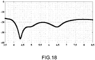
- La
figure 18 représente un exemple d'adaptation d'impédance obtenue par un système d'antenne en fonction de la fréquence dans un ensemble de modes de réalisation de l'invention ; - Le matching est représenté sur l'axe vertical, en dB, en fonction de la fréquence, sur l'axe horizontal, en GHz.
- There
figure 18 shows an example of impedance matching obtained by an antenna system as a function of frequency in a set of embodiments of the invention; - The matching is represented on the vertical axis, in dB, as a function of frequency, on the horizontal axis, in GHz.
On observe que l'ajout de la demi-lentille diélectrique absorbante n'induit pas de désadaptation de l'antenne.It is observed that the addition of the absorbing dielectric half-lens does not induce mismatching of the antenna.
Les exemples ci-dessus démontrent la capacité de l'invention à générer une déviation du faisceau d'une antenne de manière homogène sur une large bande de fréquence, tout en limitant l'encombrement du système d'antenne et en préservant les performances de l'antenne. Ils ne sont cependant donnés qu'à titre d'exemple et ne limitent en aucun cas la portée de l'invention, définie dans les revendications ci-dessous.The examples above demonstrate the ability of the invention to generate a deflection of the beam of an antenna in a homogeneous manner over a wide frequency band, while limiting the size of the antenna system and preserving the performance of the 'antenna. However, they are only given by way of example and in no way limit the scope of the invention, defined in the claims below.
Claims (12)
Applications Claiming Priority (1)
| Application Number | Priority Date | Filing Date | Title |
|---|---|---|---|
| FR2109426A FR3126818B1 (en) | 2021-09-09 | 2021-09-09 | ELECTROMAGNETIC SYSTEM WITH ANGULAR DEVIATION OF THE MAIN RADIATION LOBE OF AN ANTENNA |
Publications (1)
| Publication Number | Publication Date |
|---|---|
| EP4148902A1 true EP4148902A1 (en) | 2023-03-15 |
Family
ID=79602080
Family Applications (1)
| Application Number | Title | Priority Date | Filing Date |
|---|---|---|---|
| EP22193180.1A Pending EP4148902A1 (en) | 2021-09-09 | 2022-08-31 | Electromagnetic system with angular deviation of the main dispersion lobe of an antenna. |
Country Status (2)
| Country | Link |
|---|---|
| EP (1) | EP4148902A1 (en) |
| FR (1) | FR3126818B1 (en) |
Citations (4)
| Publication number | Priority date | Publication date | Assignee | Title |
|---|---|---|---|---|
| US5162806A (en) * | 1990-02-05 | 1992-11-10 | Raytheon Company | Planar antenna with lens for controlling beam widths from two portions thereof at different frequencies |
| US6947010B2 (en) | 2002-12-13 | 2005-09-20 | Broadcom Corporation | Eccentric spiral antenna |
| US20100328779A1 (en) * | 2009-06-30 | 2010-12-30 | California Institute Of Technolology | Dielectric covered planar antennas |
| JP2012205144A (en) * | 2011-03-25 | 2012-10-22 | Toshiba Denpa Products Kk | Spiral antenna |
-
2021
- 2021-09-09 FR FR2109426A patent/FR3126818B1/en active Active
-
2022
- 2022-08-31 EP EP22193180.1A patent/EP4148902A1/en active Pending
Patent Citations (4)
| Publication number | Priority date | Publication date | Assignee | Title |
|---|---|---|---|---|
| US5162806A (en) * | 1990-02-05 | 1992-11-10 | Raytheon Company | Planar antenna with lens for controlling beam widths from two portions thereof at different frequencies |
| US6947010B2 (en) | 2002-12-13 | 2005-09-20 | Broadcom Corporation | Eccentric spiral antenna |
| US20100328779A1 (en) * | 2009-06-30 | 2010-12-30 | California Institute Of Technolology | Dielectric covered planar antennas |
| JP2012205144A (en) * | 2011-03-25 | 2012-10-22 | Toshiba Denpa Products Kk | Spiral antenna |
Non-Patent Citations (3)
| Title |
|---|
| H. NAKANOT. ABEJ. YAMAUCHI: "A Metaspiral Antenna for Azimuthal Beam Steering", 2019 INTERNATIONAL SYMPOSIUM ON ANTENNAS AND PROPAGATION (ISAP), XI'AN, CHINA, 2019, pages 1 - 3, XP033692238 |
| P. DEOA. MEHTAD. MIRSHEKAR-SYAHKALH. NAKANO: "An HIS-Based Spiral Antenna for Pattern Reconfigurable Applications", IEEE ANTENNAS AND WIRELESS PROPAGATION LETTERS, vol. 8, 2009, pages 196 - 199 |
| TOMOKI ABEJUNJI YAMAUCHIHISAMATSU NAKANO: "Steering of the Circularly Polarized Beam from a Spiral Antenna", IEICE COMMUNICATIONS EXPRESS, 20 February 2020 (2020-02-20) |
Also Published As
| Publication number | Publication date |
|---|---|
| FR3126818A1 (en) | 2023-03-10 |
| FR3126818B1 (en) | 2024-02-23 |
Similar Documents
| Publication | Publication Date | Title |
|---|---|---|
| EP0575211B1 (en) | Radiating element of an antenna with wide bandwidth and antenna array comprising such elements | |
| EP0899814B1 (en) | Radiating structure | |
| CA2148796C (en) | Monopolar wire-plate antenna | |
| EP1979987B1 (en) | Circularly or linearly polarized antenna | |
| EP0661773A1 (en) | Conically shaped microstrip patch antenna prepared on a planar substrate and method of its manufacturing | |
| EP2658032B1 (en) | Corrugated horn antenna | |
| CA2044903C (en) | Frenquency variation scanning antenna | |
| EP2817850B1 (en) | Electromagnetic band gap device, use thereof in an antenna device, and method for determining the parameters of the antenna device | |
| EP0014605B1 (en) | Reverse cassegrain antenna for multipurpose radar | |
| EP4148902A1 (en) | Electromagnetic system with angular deviation of the main dispersion lobe of an antenna. | |
| EP0091343B1 (en) | Inverse cassegrain antenna for a multifunction radar | |
| EP3844844A1 (en) | Antenna for transmitting and/or receiving an electromagnetic wave, and system comprising this antenna | |
| FR2920917A1 (en) | SINUSOIDAL PATTERNED RADIANT BRIDGE PROPELLER TYPE ANTENNA AND METHOD OF MANUFACTURING THE SAME. | |
| FR2945674A1 (en) | Beam misaligning device for beam scanning antenna in airplane, has prisms positioned in angular manner along radiation axis and producing inflexion of beam of antenna with variable amplitude relative to angular positioning between prisms | |
| EP1350285B1 (en) | Electromagnetic probe | |
| EP3218961A1 (en) | Reconfigurable compact antenna device | |
| WO2008037887A2 (en) | Antenna using a pfb (photonic forbidden band) material and system | |
| EP0762534B1 (en) | Method for enlarging the radiation diagram of an antenna array with elements distributed in a volume | |
| EP0929914B1 (en) | High frequency antenna | |
| EP2449629B1 (en) | Omnidirectional, broadband compact antenna system comprising two highly decoupled separate transmission and reception access lines | |
| CA2800949C (en) | Linear dual-polarised wide band compact antenna | |
| FR2968848A1 (en) | PARABOLIC REFLECTOR ANTENNA | |
| EP4199258A1 (en) | Improved elementary microstrip antenna and array antenna | |
| FR3114195A1 (en) | Antenna with improved coverage over a wide frequency domain | |
| FR2803694A1 (en) | RESONANT CAVITY ANTENNA HAVING A CONFORMING BEAM ACCORDING TO A PREDETERMINED RADIATION DIAGRAM |
Legal Events
| Date | Code | Title | Description |
|---|---|---|---|
| PUAI | Public reference made under article 153(3) epc to a published international application that has entered the european phase |
Free format text: ORIGINAL CODE: 0009012 |
|
| STAA | Information on the status of an ep patent application or granted ep patent |
Free format text: STATUS: THE APPLICATION HAS BEEN PUBLISHED |
|
| AK | Designated contracting states |
Kind code of ref document: A1 Designated state(s): AL AT BE BG CH CY CZ DE DK EE ES FI FR GB GR HR HU IE IS IT LI LT LU LV MC MK MT NL NO PL PT RO RS SE SI SK SM TR |
|
| STAA | Information on the status of an ep patent application or granted ep patent |
Free format text: STATUS: REQUEST FOR EXAMINATION WAS MADE |
|
| 17P | Request for examination filed |
Effective date: 20230420 |
|
| RBV | Designated contracting states (corrected) |
Designated state(s): AL AT BE BG CH CY CZ DE DK EE ES FI FR GB GR HR HU IE IS IT LI LT LU LV MC MK MT NL NO PL PT RO RS SE SI SK SM TR |