EP4572014A1 - Rundstrahlantenne und antennenanordnung dafür. - Google Patents
Rundstrahlantenne und antennenanordnung dafür. Download PDFInfo
- Publication number
- EP4572014A1 EP4572014A1 EP24219966.9A EP24219966A EP4572014A1 EP 4572014 A1 EP4572014 A1 EP 4572014A1 EP 24219966 A EP24219966 A EP 24219966A EP 4572014 A1 EP4572014 A1 EP 4572014A1
- Authority
- EP
- European Patent Office
- Prior art keywords
- antenna
- radiating element
- radiation pattern
- antenna according
- omnidirectional
- Prior art date
- Legal status (The legal status is an assumption and is not a legal conclusion. Google has not performed a legal analysis and makes no representation as to the accuracy of the status listed.)
- Pending
Links
Images


Classifications
-
- H—ELECTRICITY
- H01—ELECTRIC ELEMENTS
- H01Q—ANTENNAS, i.e. RADIO AERIALS
- H01Q9/00—Electrically-short antennas having dimensions not more than twice the operating wavelength and consisting of conductive active radiating elements
- H01Q9/04—Resonant antennas
- H01Q9/0407—Substantially flat resonant element parallel to ground plane, e.g. patch antenna
- H01Q9/0471—Non-planar, stepped or wedge-shaped patch
-
- H—ELECTRICITY
- H01—ELECTRIC ELEMENTS
- H01Q—ANTENNAS, i.e. RADIO AERIALS
- H01Q9/00—Electrically-short antennas having dimensions not more than twice the operating wavelength and consisting of conductive active radiating elements
- H01Q9/04—Resonant antennas
- H01Q9/16—Resonant antennas with feed intermediate between the extremities of the antenna, e.g. centre-fed dipole
- H01Q9/28—Conical, cylindrical, cage, strip, gauze, or like elements having an extended radiating surface; Elements comprising two conical surfaces having collinear axes and adjacent apices and fed by two-conductor transmission lines
-
- H—ELECTRICITY
- H01—ELECTRIC ELEMENTS
- H01Q—ANTENNAS, i.e. RADIO AERIALS
- H01Q19/00—Combinations of primary active antenna elements and units with secondary devices, e.g. with quasi-optical devices, for giving the antenna a desired directional characteristic
- H01Q19/02—Details
- H01Q19/021—Means for reducing undesirable effects
Definitions
- the present invention relates to an omnidirectional radiation antenna and an antenna assembly comprising such an antenna. More specifically, the invention relates to a hemispherical antenna having an omnidirectional radiation pattern.
- an omnidirectional radiation pattern antenna or omnidirectional antenna.
- an omnidirectional antenna is used as a common radio frequency antenna at the center of a hemispherical array antenna.
- a hemispherical array antenna comprises a plurality of radiating elements carried by the external surface of a hemispherical radome.
- the internal surface of this radome carries a plurality of transmitting/receiving modules, each transmitting/receiving module addressing one or more associated radiating elements.
- a wireless link for example a radio frequency - RF link.
- each transmitter/receiver module is equipped with an individual RF antenna
- the low-level electronics are connected to a common RF antenna.
- the common RF antenna is placed at the center of the hemisphere formed by the array antenna, or near the center, in particular slightly set back from the center along the antenna's axis of symmetry to compensate for too small an opening of the antenna's main lobe.
- the aim is to use an omnidirectional antenna capable of producing hemispherical radiation, i.e. one whose main lobe of the radiation pattern has a solid opening angle of 2 ⁇ , to excite the transmission/reception modules distributed over the hemispherical radome.
- antennas that are presented as omnidirectional, such as dipole antennas, monopole antennas, collinear antennas, helical antennas, etc.
- these antennas do not generate an omnidirectional radiation pattern: if at a very high attenuation (-12dB), the effective radiation pattern can approach an omnidirectional radiation pattern, the more the attenuation is reduced (-6dB) and the more the effective radiation pattern deviates from an omnidirectional radiation pattern.
- the radome which carries a metal layer, internally delimits a cavity, which confines the electromagnetic waves.
- the RF signals emitted by the common antenna and each of the individual antennas of the transmitting/receiving modules are confined inside this cavity, so that the background noise level inside the cavity is high.
- the implemented antenna must be able to operate well above the background noise level, i.e. it must exhibit an omnidirectional radiation pattern even at low attenuation (around -3dB).
- the aim of the invention is therefore to propose an antenna that can address this problem.
- the invention relates to an omnidirectional antenna and an antenna assembly comprising such an omnidirectional antenna in accordance with the appended claims.
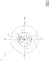
- THE figures 1 , 2 And 3 illustrate a preferred embodiment of an antenna assembly 10 according to the invention.
- the antenna assembly 10 comprises an omnidirectional antenna 20 and a support element 30 for this omnidirectional antenna.
- the omnidirectional antenna 20 is hemispherical. It has the shape of a half-sphere with center O and radius R.
- An XYZ coordinate system is attached to the center O of the hemisphere.
- the antenna element 10 is symmetrical with respect to the YZ plane and with respect to the XZ plane.
- the omnidirectional antenna 20 successively comprises, from the inside to the outside, a metal layer 22 forming the electrical mass, a support layer 24 and a metal radiating element, or “patch”, 26.
- the support layer 24 forms a hemispherical dome, the outer surface of which is at the distance R from the center O.
- the support layer 24 is made of a dielectric material whose relative permittivity is adapted.
- the metal layer 22 covers the inner surface of the support layer 24.
- a patch is a planar radiating element, according to the present invention, it is a three-dimensional radiating element, shaped on the outer surface of the support layer 24, and consequently constituting a curved surface. At the apex point B for example, this surface has both a non-zero curvature in the YZ plane and a non-zero curvature in the XZ plane.
- Patch 26 is bounded by two longitudinal edges, 33 and 34, and by lateral edges, 35 and 36.
- a low attenuation omnidirectional radiation pattern is obtained by adapting the curvature of the edges of the radiating element.
- the longitudinal edge 33 correspond to the intersection of the sphere of center O and radius R and a horizontal plane, parallel to the XY plane, but at a height h above it.
- the lateral edges are on a circle of radius Rp whose center is on the Z axis.
- the longitudinal edges In top view ( Figure 1 ), the longitudinal edges have a concavity oriented towards the center O of the antenna 20. They have an adapted curvilinear length L2.
- the lateral edge 35 correspond to the intersection of the sphere of center O and radius R and a cylinder of axis C2, respectively a cylinder of axis C1, and radius Rc, the axis C2, respectively the axis C1, being parallel to the axis Z and lying in the plane XZ.
- the longitudinal edges have a concavity oriented away from the center O of the antenna 20. They have a suitable curvilinear length L3.
- the lateral edges correspond to the intersection of the sphere with center O and radius R and a cylinder with elliptical section.
- the distance between the C1 axis, respectively C2, and the Z axis also allows, by modifying the position of the corners of the patch, to reduce the length L3 by increasing the length L2.
- the excitation of the patch 26 is carried out by a port P.
- the port P is connected to the core 42 of a coaxial cable 40 allowing the connection of the radiating element of the omnidirectional antenna 20 to the low-level electronics (not shown in the figures).
- the core circulates through a via 25 arranged through the metal layer 22 and the support layer 24.
- the sheath 44 of the coaxial cable 40 is electrically connected to the metal layer 22, i.e. to the ground potential.
- point P is located in the YZ plane of symmetry of patch 26, but outside the Z axis.
- the offset of point P relative to apex B of patch 26 makes it possible to adjust the impedance of the patch to, for example, 50 Ohms while operating the patch in a mode similar to the TM10 mode of a planar radiating element.
- adjusting the curvature of the edges of the “patch” makes it possible to play on the diffraction phenomena at the edges of the patch to obtain hemispherical radiation.
- a convex shape of the lateral edges 33 and 34 advantageously follows a line of iso amplitude of the electric field.
- the field evolves between its maximum values along the lateral edges 35 and 36.
- a concave shape of the lateral edges makes it possible to compensate for the asymmetry of the field according to the XOZ plane.
- the aim is to adjust the radiation pattern for a given resonance frequency F0.
- F0 resonance frequency
- the support element 30 is of truncated cone shape around the Z axis. Its large base is circular, of radius R0, and its small base is circular with center 0 and radius R.
- the support element 30 has a height h0. It has a half-opening at the apex A of the cone equal to ⁇ .
- the support element 30 consists of a metallic side wall 23.
- the small base of the support element 30 has an annular collar 31 which is also metallic.
- the metallic layer 22, the collar 31 and the side wall 32 form an equipotential brought to the ground potential.
- the antennal element just presented can have a large number of variants.
- the antenna element can be limited to the omnidirectional antenna, without a support element.
- the opening angle is greater than 180°.
- Such an opening angle is too large for the common RF antenna application in a hemispherical array antenna.
- the metal support element then advantageously allows to "repel" the electric field and thus reduce the opening of the radiating element compared to that of the isolated omnidirectional antenna.
- the shape of the support element the radiation pattern can be adapted. For example, by varying the value of the half-opening angle. For example, by varying the contour of the large base of the support element, which instead of being circular could be elliptical or peanut-shaped.
- the radiating element could be excited by a plurality of ports, including a pair of differentially fed ports.
- the excitation of the radiating element can use any known technique (via feed, slot feed, etc.).
- the value of the relative permittivity of the dielectric material constituting the support can also be adjusted.
- the omnidirectional antenna has the advantage of generating an electromagnetic wave that is homogeneous in amplitude, with linear polarity throughout the half-space.
- the antenna with or without its support element remains compact, which facilitates its integration, particularly in the case of use as a central RF antenna housed inside a hemispherical radome.
Landscapes
- Waveguide Aerials (AREA)
- Aerials With Secondary Devices (AREA)
Applications Claiming Priority (1)
| Application Number | Priority Date | Filing Date | Title |
|---|---|---|---|
| FR2314287A FR3157020A1 (fr) | 2023-12-15 | 2023-12-15 | Antenne omnidirectionnelle et ensemble antennaire associé. |
Publications (1)
| Publication Number | Publication Date |
|---|---|
| EP4572014A1 true EP4572014A1 (de) | 2025-06-18 |
Family
ID=91248088
Family Applications (1)
| Application Number | Title | Priority Date | Filing Date |
|---|---|---|---|
| EP24219966.9A Pending EP4572014A1 (de) | 2023-12-15 | 2024-12-13 | Rundstrahlantenne und antennenanordnung dafür. |
Country Status (2)
| Country | Link |
|---|---|
| EP (1) | EP4572014A1 (de) |
| FR (1) | FR3157020A1 (de) |
Citations (2)
| Publication number | Priority date | Publication date | Assignee | Title |
|---|---|---|---|---|
| US6281847B1 (en) | 1998-12-17 | 2001-08-28 | Southern Methodist University | Electronically steerable and direction finding microstrip array antenna |
| KR200313932Y1 (ko) * | 2003-02-14 | 2003-05-22 | 정부교 | 전방향 수신형 위성 안테나 구조 |
-
2023
- 2023-12-15 FR FR2314287A patent/FR3157020A1/fr active Pending
-
2024
- 2024-12-13 EP EP24219966.9A patent/EP4572014A1/de active Pending
Patent Citations (2)
| Publication number | Priority date | Publication date | Assignee | Title |
|---|---|---|---|---|
| US6281847B1 (en) | 1998-12-17 | 2001-08-28 | Southern Methodist University | Electronically steerable and direction finding microstrip array antenna |
| KR200313932Y1 (ko) * | 2003-02-14 | 2003-05-22 | 정부교 | 전방향 수신형 위성 안테나 구조 |
Non-Patent Citations (3)
| Title |
|---|
| FERREIRA D B ET AL: "An efficient approach to the analysis and synthesis of spherical-circular thin microstrip antennas", ANTENNAS AND PROPAGATION SOCIETY INTERNATIONAL SYMPOSIUM (APSURSI), 2010 IEEE, IEEE, PISCATAWAY, NJ, USA, 11 July 2010 (2010-07-11), pages 1 - 4, XP032146197, ISBN: 978-1-4244-4967-5, DOI: 10.1109/APS.2010.5562184 * |
| GREGORY H HUFF ET AL: "A Spherical Inverted-F Antenna (SIFA)", IEEE ANTENNAS AND WIRELESS PROPAGATION LETTERS, IEEE, PISCATAWAY, NJ, US, vol. 8, 1 January 2009 (2009-01-01), pages 649 - 652, XP011257495, ISSN: 1536-1225 * |
| HUFF G.H: "ANTENNAS AND WIRELESS PROPAGATION LETTERS", IEEE, article "A Spherical Inverted-F Antenna (SIFA)" |
Also Published As
| Publication number | Publication date |
|---|---|
| FR3157020A1 (fr) | 2025-06-20 |
Similar Documents
| Publication | Publication Date | Title |
|---|---|---|
| CA2004870C (fr) | Dispositif rayonnant multifrequence | |
| EP0899814B1 (de) | Strahlende Struktur | |
| FR2626980A1 (fr) | Transpondeur de radar secondaire | |
| EP3844844A1 (de) | Antenne zum senden und/oder empfangen einer elektromagnetischen welle und system mit dieser antenne | |
| EP1188202B1 (de) | Anordnung zur übertragung und/oder zum empfang von signalen | |
| EP2610966B1 (de) | Kompakte Breitbandantenne von sehr geringer Dicke und mit doppelten orthogonalen linearen Polarisierungen, die für den V/UHF-Bandbereich konzipiert ist | |
| EP1554777A1 (de) | Mehrfachstrahlantenne mit photonischem bandlückenmaterial | |
| EP0131512A1 (de) | Doppelreflektorantenne mit fast ringflächiger Strahldeckung | |
| EP4572014A1 (de) | Rundstrahlantenne und antennenanordnung dafür. | |
| EP3175509B1 (de) | Logarithmisch-periodische antenne mit breitem frequenzband | |
| Hinostroza | Design of wideband arrays of spiral antennas. | |
| EP0860895A1 (de) | Resonanzantenne zum Senden oder Empfangen polarisierter Wellen | |
| EP4148902A1 (de) | Elektromagnetisches system mit winkelabweichung der hauptkeule einer antenne | |
| EP4203191A1 (de) | Planare zirkular polarisierte hochfrequenzantenne | |
| EP4167378A1 (de) | Isolierte hochfrequenzantennenanordnung | |
| JPH06291538A (ja) | マイクロ波偏波レンズ装置 | |
| EP4396901B1 (de) | Mehrbandantenne | |
| FR3108797A1 (fr) | Antenne directive large bande à émission longitudinale | |
| EP2610965B1 (de) | Kompakte Breitbandantenne mit doppelter Linearpolarisation | |
| EP2889955B1 (de) | Kompaktantennenstruktur für Telekommunikationen über Satelliten | |
| FR3152197A1 (fr) | Système de réseau d’antennes multi-bandes et superdirectif | |
| FR3152094A1 (fr) | Système antennaire et antenne réseau correspondante | |
| WO2015189134A1 (fr) | Antenne plate de telecommunication par satellite | |
| FR3151945A1 (fr) | Antenne à réseau transmetteur | |
| FR3157019A1 (fr) | Antenne réseau hémisphérique améliorée |
Legal Events
| Date | Code | Title | Description |
|---|---|---|---|
| PUAI | Public reference made under article 153(3) epc to a published international application that has entered the european phase |
Free format text: ORIGINAL CODE: 0009012 |
|
| STAA | Information on the status of an ep patent application or granted ep patent |
Free format text: STATUS: THE APPLICATION HAS BEEN PUBLISHED |
|
| AK | Designated contracting states |
Kind code of ref document: A1 Designated state(s): AL AT BE BG CH CY CZ DE DK EE ES FI FR GB GR HR HU IE IS IT LI LT LU LV MC ME MK MT NL NO PL PT RO RS SE SI SK SM TR |
|
| STAA | Information on the status of an ep patent application or granted ep patent |
Free format text: STATUS: REQUEST FOR EXAMINATION WAS MADE |
|
| 17P | Request for examination filed |
Effective date: 20251120 |