EP4148486A1 - Gläser - Google Patents
Gläser Download PDFInfo
- Publication number
- EP4148486A1 EP4148486A1 EP21803591.3A EP21803591A EP4148486A1 EP 4148486 A1 EP4148486 A1 EP 4148486A1 EP 21803591 A EP21803591 A EP 21803591A EP 4148486 A1 EP4148486 A1 EP 4148486A1
- Authority
- EP
- European Patent Office
- Prior art keywords
- connecting member
- glasses
- elastic
- main body
- glasses leg
- Prior art date
- Legal status (The legal status is an assumption and is not a legal conclusion. Google has not performed a legal analysis and makes no representation as to the accuracy of the status listed.)
- Granted
Links
Images


Classifications
-
- G—PHYSICS
- G02—OPTICS
- G02C—SPECTACLES; SUNGLASSES OR GOGGLES INSOFAR AS THEY HAVE THE SAME FEATURES AS SPECTACLES; CONTACT LENSES
- G02C5/00—Constructions of non-optical parts
- G02C5/22—Hinges
- G02C5/2218—Resilient hinges
- G02C5/2227—Resilient hinges comprising a fixed hinge member and a coil spring
-
- G—PHYSICS
- G02—OPTICS
- G02C—SPECTACLES; SUNGLASSES OR GOGGLES INSOFAR AS THEY HAVE THE SAME FEATURES AS SPECTACLES; CONTACT LENSES
- G02C5/00—Constructions of non-optical parts
- G02C5/22—Hinges
- G02C5/2218—Resilient hinges
- G02C5/2254—Resilient hinges comprising elastic means other than coil spring
-
- G—PHYSICS
- G02—OPTICS
- G02C—SPECTACLES; SUNGLASSES OR GOGGLES INSOFAR AS THEY HAVE THE SAME FEATURES AS SPECTACLES; CONTACT LENSES
- G02C2200/00—Generic mechanical aspects applicable to one or more of the groups G02C1/00 - G02C5/00 and G02C9/00 - G02C13/00 and their subgroups
- G02C2200/12—Frame or frame portions made from sheet type material
-
- G—PHYSICS
- G02—OPTICS
- G02C—SPECTACLES; SUNGLASSES OR GOGGLES INSOFAR AS THEY HAVE THE SAME FEATURES AS SPECTACLES; CONTACT LENSES
- G02C2200/00—Generic mechanical aspects applicable to one or more of the groups G02C1/00 - G02C5/00 and G02C9/00 - G02C13/00 and their subgroups
- G02C2200/28—Coil spring twisted upon actuation
Definitions
- This application belongs to the field of intelligent wearable technologies, and in particular, to a kind of glasses.
- An objective of embodiments of this application is to provide a new technical solution of glasses, to resolve technical problems of infirm wearing and low flexibility of an existing glasses leg.
- Glasses including a main body, a glasses leg, and a connecting device, where the glasses leg is connected to an end portion of the main body through the connecting device, so that the glasses leg is rotatable;
- the connecting device includes a first connecting member, a second connecting member, and an elastic member, where the first connecting member is arranged on the end portion of the main body, a first end of the second connecting member is hinged with the first connecting member, a second end of the second connecting member is hinged with the glasses leg, and the elastic member is located between the second connecting member and the glasses leg, where a first elastic end of the elastic member abuts against the glasses leg, a second elastic end of the elastic member abuts against the second connecting member, and in a case that the glasses leg rotates away from the main body, the elastic member drives the glasses leg and the second connecting member to be away from each other.
- the glasses leg is connected to the main body through the connecting device, and the second connecting member of the connecting device is hinged with the glasses leg. Therefore, after the glasses leg is hung on a head, the elastic member can automatically drive the glasses leg to clamp the head, to achieve a firm wearing effect of the glasses and improve the flexibility.
- first connecting member 31: first limiting portion; 32: first hinge hole; 4: second connecting member; 41: first end; 42: second end; 43: first through hole; 431: first side hole wall; 432: second side hole wall; 44: mounting shaft; 45: first mounting hole; 46: second hinge hole; 47: third hinge hole; 5: first columnar portion; 6: torsion spring; 61: first torsion arm; 62: second torsion arm; 7: first shaft; and 8: second shaft.
- an embodiment of this application provides glasses, including a main body 1, a glasses leg 2, and a connecting device, where the glasses leg 2 is connected to an end portion of the main body 1 through the connecting device, so that the glasses leg 2 is rotatable.
- the glasses described in this embodiment are any one of myopia glasses, sunshade glasses, virtual reality (Virtual Reality, VR) glasses, or electronic smart glasses.
- a type of glasses is not limited in this embodiment of this application. A person skilled in the art may apply this technical solution to the required glasses.
- the connecting device includes a first connecting member 3, a second connecting member 4, and an elastic member, where the first connecting member 3 is arranged on the end portion of the main body 1, and may be fixedly connected to the main body 1, so that the main body 1 is stably connected to the glasses leg.
- a first end 41 of the second connecting member 4 is hinged with the first connecting member 3.
- the second connecting member 4 and the first connecting member 3 form a rotatable engagement relationship, so that a component fixedly connected to the second connecting member 4 can rotate relative to the main body 1 and the first connecting member 3.
- a second end 42 of the second connecting member 4 is hinged with the glasses leg 2, so that the second connecting member and the glasses leg also form a rotatable engagement relationship.
- the elastic member is located between the second connecting member 4 and the glasses leg 2, where a first elastic end of the elastic member abuts against the glasses leg 2, and a second elastic end of the elastic member abuts against the second connecting member 4.
- the elastic member is configured to form a pre-tightening elastic force between the second connecting member 4 and the glasses leg 2, so that in actual application, the glasses leg 2 can generate an elastic effect of clamping in an opposite direction when being pulled and rotating relative to the second connecting member 4.
- a main structure of the elastic member may be fixed on the second connecting member, and the elastic member is mainly in contact with the glasses leg 2 through the first elastic end, to generate an elastic force.
- the elastic member is closer to the main body 1, which helps to improve the connection reliability among the elastic member, the glasses leg 2, and the main body.
- the main structure of the elastic member may alternatively be fixed on the glasses leg 2, and the elastic member is mainly in contact with the second connecting member 4 through the second elastic end, to generate an elastic force.
- a rotatable range of the glasses leg 2 and the second connecting member 4 is designed to be larger, to increase a movable range of the glasses leg 2 relative to the second connecting member 4 and the main body 1.
- the glasses leg 2 and the second connecting member 4 may be designed into a flat strip-shaped or sheet-shaped structure, so as to improve the aesthetics of the glasses.
- the entire elastic member may be located at an inner side of the glasses leg 2 and the second connecting member 4, that is, at a side closer to a wearer, to improve the overall aesthetics of the glasses.
- the entire elastic member may be located at an outer side of the glasses leg 2 and the second connecting member 4, that is, at a side away from the wearer. This design is more convenient for the elastic member to play a role of clamping the glasses leg on the wearer's head, and the structure is simple.
- a part of the elastic member may alternatively be arranged on the side close to the wearer, and an other part of the elastic member is arranged on the side away from the wearer, so as to design the structure of the second connecting member and the glasses leg. This is not limited in this application.
- the hinge between the first end of the second connecting member and the first connecting member allows the second connecting member and the glasses leg to rotate relative to the main body, so that the glasses leg and the main body may be folded, to reduce the volume of the glasses, thereby facilitating storage.
- the hinge between the second end of the second connecting member and the glasses leg allows the glasses leg to rotate relative to the second connecting member, so that the glasses leg is adapted to the head sizes of different wearers.
- the glasses leg rotates away from the main body, the glasses legis first unfolded, and the second connecting member and the glasses leg synchronously rotate to a position convenient for the wearer to wear.
- the glasses leg further rotates away from the main body, the glasses leg rotates relative to the second connecting member to adapt to the size of the wearer's head.
- the elastic member is deformed to store energy, and the elastic member has a characteristic of returning to an original state, so that the elastic member drives the glasses leg and the second connecting member to move away from each other, the glasses leg may be fastened on the wearer's head, the glasses are firmly worn, and the flexibility is improved.
- the glasses leg 2 of the glasses is connected to the main body 1 through the connecting device, and the second connecting member 4 of the connecting device is hinged with the glasses leg 2. Therefore, after the glasses leg 2 is hung on an ear, the elastic member can automatically drive the glasses leg 2 to be clamped on the head, so as to achieve a firm wearing effect of the glasses and improve the flexibility.
- the glasses may also have two glasses legs.
- one glasses leg is connected to one end of the main body
- the other glasses leg is connected to the other end of the main body
- the two glasses legs may be connected to the main body through the connecting devices respectively. It may be understood that, rotation directions of the two glasses legs are opposite.
- the two glasses legs 2 rotate away from the main body and are unfolded.
- the glasses legs 2 drive, through the elastic members, the second connecting members 4 to rotate by using hinge points between the second connecting members 4 and the first connecting members 1 as centers.
- the elastic members drive the glasses legs 2 to move close to the main body, so that the two glasses legs 2 are clamped on the head.
- the second connecting member 4 is hinged with the glasses leg 2. After the two glasses legs 2 are unfolded and parallel to each other, if the width between the two glasses legs 2 is still less than a width of the wearer's head, the wearer may respectively pull the two glasses legs 2 outward to increase the width between the glasses legs, and the glasses legs 2 rotate by using the hinge points as the centers.
- the elastic member is deformed due to a pulling force exerted by the wearer, to produce an elastic force on the glasses leg 2.
- the glasses legs 2 tend to close to each other under the action of the elastic forces. In this way, the two glasses legs 2 can be clamped on the head of the wearer to ensure the wearing stability.
- the two glasses legs 2 rotate around the second connecting members under the action of the elastic members, and move back toward each other.
- the wearer may rotate the glasses legs outward by 0-30° by pulling the glasses legs.
- the glasses in this embodiment also achieves an effect of adjusting the width between the two glasses legs 2 without the deformation of the glasses legs.
- the glasses may be used by people with different head widths without additionally setting a plurality of specifications, thereby reducing production costs and procurement costs
- the first connecting member 3 includes a first limiting portion 31, and the first limiting portion 31 is arranged on an end of the first connecting member 3 adjacent to the second connecting member 4.
- the second connecting member 4 rotates away from the main body 1 relative to the first connecting member 3 to a preset angle range
- the second connecting member 4 abuts against the first limiting portion 31, so as to limit the second connecting member and prevent the second connecting member and the glasses leg from further rotating relative to each other, so that the second connecting member 4 and the glasses leg 2 rotate within a range between the main body 1 and the first limiting portion 31.
- the first limiting portion 31 may be arranged on a side of the first connecting member 3 away from the main body.
- the second connecting member 4 rotates by 90° away from the main body 1, the second connecting member 4 abuts against the first limiting portion 31.
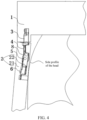
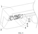
- FIG. 5 when the second connecting member 4 rotates by 90° close to the main body 1, one of the glasses legs 2 abuts against the main body 1.
- the second connecting members 4 on two ends of the main body 1 are parallel to each other, and the glasses legs 2 on the two ends of the main body 1 are parallel to each other.
- a rotatable angle of the second connecting member 4 is not limited to 90°, and may be less than 90° or greater than 90°.
- a person skilled in the art may set a shape and a position of the first limiting portion according to an actual requirement, so as to limit a movable angle range of the second connecting member 4.
- the first limiting portion 31 may be arranged on an upper end surface or a lower end surface of an end of the first connecting member 3 adjacent to the second connecting member 4.
- the first limiting portion 31 is a sheet-shaped structure extending from the first connecting member 3.
- a surface of the first limiting portion and a surface of the second connecting member 4 are in contact with a surface of the sheet-shaped first limiting portion 31.
- the first limiting portion 31 and the first connecting member 3 may be integrally formed to improve an overall strength.
- the first limiting portion 31 and the first connecting member 3 are not limited to integral forming, and may also be any one of welding, riveting, or bolt connection. A person skilled in the art may set a connection relationship between the first limiting portion 31 and the first connecting member 3 according to an actual requirement.
- the first limiting portion By arranging the first limiting portion, a phenomenon of excessive pulling can be avoided when the wearer pulls the glasses leg from a position close to the main body to a position away from the main body.
- the first limiting portion can limit a maximum rotational posture of the second connecting member relative to the main body, so that the glasses can be worn on the head normally and stably.
- the second end 42 of the second connecting member 4 is provided with a second limiting portion, the second limiting portion has a preset limit angle, and the glasses leg 2 can rotate within the preset limit angle. Because the glasses leg 2 is rotatable within the preset limit angle as limited by the second limiting member, the degree of rotation of the glasses leg 2 can be controlled.
- the preset limit angle is ⁇ 30°. That is, when the glasses leg 2 automatically rotates inward by 30° under the driving of the elastic member, the glasses leg abuts against a part of the second limiting portion, and stops the inward rotation.
- the glasses leg 2 When the glasses leg 2 is pulled outward by using a hand to rotate outward by 30°, the glasses leg abuts against another part of the second limiting portion, and stops the outward rotation. In this case, the width between the two glasses legs 2 may be increased for people with a large head width to use.
- the preset limit angle of the second limiting portion for the glasses leg 2 is not limited to ⁇ 30°. A person skilled in the art may set the limit angle of the second limiting portion according to an actual requirement.
- Inconvenience caused by excessive rotation of the glasses leg relative to the second connecting member may be effectively avoided by arranging the second limiting portion. In addition, it can also reduce a risk of damage to the glasses and a risk of breakage between the glasses leg and the second connecting member.
- the second limiting portion includes a first through hole 43, a first columnar portion 5 is arranged between the glasses leg 2 and the second connecting member 4, and the first columnar portion 5 is movable in the first through hole 43.
- the first through hole 43 is provided on the second end 42 of the second connecting member 4, the first columnar portion 5 is arranged on the glasses leg 2, and the first columnar portion 5 is inserted into the first through hole 43.
- a diameter of the first through hole 43 is greater than a diameter of the first columnar portion 5, so that the first columnar portion 5 is movable within the first through hole 43.
- the glasses leg 2 when the glasses leg 2 automatically rotates close to the main body under the driving of the elastic member by 30°, the first columnar portion 5 on the glasses leg 2 abuts against a first side hole wall 431 of the first through hole 43 of the second connecting member 4, to limit the glasses leg 2. Through a limiting action of the first through hole 43, the glasses leg 2 cannot rotate further.
- the first columnar portion 5 on the glasses leg 2 abuts against a second side hole wall 432 of the first through hole 43 of the second connecting member 4, to limit the glasses leg.
- the glasses leg 2 cannot be pulled further away from the main body, and stops the outward rotation.
- the width between the two glasses legs 2 may be increased for people with the large head width to use.
- sizes of the first columnar portion and the first through hole may be preset, to limit the rotatable angle of the glasses leg relative to the second connecting member, so as to facilitate the use and pulling of the wearer without occurrence of excessive pulling of the glasses leg.
- a larger diameter of the first columnar portion indicates a smaller rotatable angle range of the glasses leg relative to the second connecting member; and a smaller diameter of the first columnar portion indicates a larger rotatable angle range of the glasses leg relative to the second connecting member.
- a smaller diameter of the first through hole indicates a smaller rotatable angle range of the glasses leg relative to the second connecting member; and a larger diameter of the first through hole indicates a larger rotatable angle range of the glasses leg relative to the second connecting member.
- An advantage of this configuration of the second limiting portion is that the second limiting portion and the through hole have a good and stable relationship.
- the second limiting portion and the first columnar portion form a plug-in relationship, which is not easy to loose, separate from each other, and cause a limit failure.
- the processing and assembly process of this structure is simple.
- the second limiting portion may also be implemented by using another structure.
- the second limiting portion may use a sheet-shaped extension structure similar to the first limiting portion.
- a sheet-shaped structure may extend from a position away from the main body on the second connecting member, to limit the position of the glasses leg. In a case that the glasses leg is pulled away from the main body under the action of an external force, the glasses leg abuts against the sheet-shaped structure after rotating by a certain angle.
- the second limiting portion of the sheet-shaped structure may limit the glasses leg.
- a sheet-shaped structure may also extend from a position close to the main body on the second connecting member.
- the surface of the glasses leg may abut against the sheet-shaped structure on the second connecting member close to the main body under the action of the elastic member, to limit the glasses leg.
- the second limiting portion can also limit the glasses leg, and the structure is simple and easy to assemble.
- the rotatable angle range of the glasses leg may be limited.
- the two sheet-shape structures may be designed according to an actual product requirement to limit the angles in two directions, or only one of the sheet-shaped structures may be selected, to limit the angle in one direction.
- the elastic member is a torsion spring 6, and the torsion spring 6 is arranged on the second connecting member 4 through a mounting shaft 44.
- a first torsion arm 61 of the torsion spring 6 is configured as the first elastic end, the first torsion arm 61 abuts against the glasses leg 2, a second torsion arm 62 of the torsion spring 6 is configured as the second elastic end, and the second torsion arm 62 abuts against the second connecting member 4.
- the material of the torsion spring 6 is any one of a silicon manganese spring steel wire, a chrome vanadium spring steel wire, or a chrome silicon spring steel wire.
- the first torsion arm 61 of the torsion spring 6 may store and release elastic potential energy generated by the rotation of the glasses leg 2.
- the torsion spring 6 can produce a stable and reliable elastic force on the second connecting member and the glasses leg that are in rotatable engagement, so that the glasses leg can produce a clamping force close to the wearer's head.
- the first torsion arm and the second torsion arm of the torsion spring abut against the glasses leg and the second connecting member respectively, to effectively transmit the elastic force.
- a counterbore may be formed on the second connecting member and/or the glasses leg. End portions of the first torsion arm and the second torsion arm may be bent and inserted into the counterbore, so as to avoid dislocations of the torsion arms relative to the components against which the torsion arms abut.
- a positioning groove may alternatively be provided on the second connecting member and/or the glasses leg to limit the position of the torsion arm.
- a first mounting hole 45 is provided on the second connecting member 4, the mounting shaft 44 is arranged in the first mounting hole 45, and the torsion spring 6 is sleeved over the mounting shaft 44.
- an annular part of a middle part of the torsion spring 6 is sleeved over the mounting shaft 44, and the mounting shaft 44 is fixed on the second connecting member 4 through the first mounting hole 45.
- the first torsion arm 61 abuts against a side of the glasses leg 2 away from the main body 1; and the second torsion arm 62 abuts against a side of the second connecting member 4 away from the main body 1.
- the torsion spring can produce an elastic force, to cause the glasses leg to tend to move close to the main body.
- the torsion spring may have a certain pre-tightening force, so that the first torsion arm 61 of the torsion spring 6 always exerts a thrust on the glasses leg 2 to cause the glasses leg to rotate close to the main body, so as to achieve an automatic clamping effect of the glasses leg 2. After the wearer wears the glasses, the glasses leg can be clamped on the wearer's head under the elastic force to improve the wearing reliability.
- the elastic member may alternatively be an elastic member such as a leaf spring or an elastic rubber that can generate the elastic force.
- the elastic member is the leaf spring.
- a middle part of the leaf spring is fixed on the second connecting member 4.
- the fixing method may be welding or bolting on the second connecting member 4.
- a person skilled in the art may set a connection manner for the leaf spring according to an actual requirement.
- a first torsion arm of the leaf spring is configured as the first elastic end, and the first torsion arm abuts against a side of the glasses leg 2 away from the main body 1.
- a second torsion arm of the leaf spring is configured as the second elastic end, and the second elastic end abuts against a side of the second connecting member 4 away from the main body 1. That is, the first torsion arm of the leaf spring always releases a thrust on the glasses leg 2 to cause the glasses leg to rotate inward, so as to achieve the automatic clamping effect of the glasses leg 2.
- the leaf spring is assembled in a simpler way, and the connection relationship between the second connecting member and the glasses leg can be simplified.
- the leaf spring can also provide a stable elastic deformation force.
- the glasses leg 2 includes a leg body 21 and a third connecting member 22 connected to the leg body 21, and the third connecting member 22 is hinged with the second end 42 of the second connecting member 4.
- the elastic member is located between the third connecting member 22 and the second connecting member 4, the first elastic end of the elastic member abuts against the third connecting member 22, the second elastic end of the elastic member abuts against the second connecting member 4, and in a case that the third connecting member 22 rotates away from the main body 1, the elastic member drives the third connecting member 22 and the second connecting member 4 to be away from each other.
- the leg body 21 is connected to an end of the third connecting member 22 away from the second connecting member 4.
- the connection method is screw connection.
- the two glasses legs 2 are unfolded outward.
- the leg bodies 21 drive the second connecting members 4 to rotate relative to the main body 1 through the third connecting members 22 and the elastic members.
- the elastic members drive the third connecting members 22 and the leg bodies 21 to move close to the main body 1 (that is, rotate inward), so that the two leg bodies 21 are clamped on the head.
- the second connecting members 4 are hinged with the third connecting members 22, and the leg bodies 21 are fixedly connected to the third connecting members 22, after the second connecting members and the leg bodies 21 are fully unfolded relative to the main body 1 and parallel to each other, if the width between the two leg bodies 21 is still less than the width of the wearer's head, the wearer can rotate the two leg bodies 21 outward respectively to increase the width, and the leg bodies 21 drive the third connecting members 22 to rotate by using hinge points as axis centers, for example, the third connecting members rotate by 1° to 30°. Therefore, the leg bodies 21 drive the third connecting members 22 to rotate away from the main body 1. In this case, the elastic members are elastically deformed to generate an elastic force. After the glasses are worn, the elastic members drive the third connecting members 22 and the leg bodies 21 to clamp toward directions of the glasses legs 2 close to the main body 1.
- the third connecting member may be made of materials that have good structure strength and are conducive to achieving stable rotatable connection.
- the leg body may be made of materials that have good skin affinity and more beautiful appearance. This design method can better meet a performance requirement of the glasses.
- the first connecting member 3, the second connecting member 4, and the third connecting member 22 are all channel plates, the first end 41 of the second connecting member 4 is sleeved in an end of the first connecting member 3, the second end 42 of the second connecting member 4 is sleeved in an end of the third connecting member 22, and the first columnar portion 5 is arranged on a second mounting hole 222 of the third connecting member 22, and inserted in the first through hole 43 of the second connecting member 4, so that the degree of rotation of the third connecting member 22 and the leg body 21 can be controlled.
- areas of the components can be increased by configuring the components as the channel plates, so as to improve the wearing comfort of the wearer and reduce possible wearing discomfort caused by applying the force.
- the strength of the channel plate structure is higher, and the structural reliability of each connecting member is improved.
- the first connecting member 3, the second connecting member 4, and the third connecting member 22 are not limited to the channel plates. A person skilled in the art may set shapes of the first connecting member 3, the second connecting member 4, and the third connecting member 22 according to actual requirements.
- opposing first hinge holes 32 are respectively provided on two side wall plates at an end of the first connecting member 3.
- Opposing second hinge holes 46 are respectively provided on two side wall plates at the first end 41 of the second connecting member 4.
- Opposing third hinge holes 47 are respectively provided on two side wall plates at the second end 42 of the second connecting member 4.
- Opposing fourth hinge holes 221 are respectively provided on two side wall plates at an end of the third connecting member 22, the first hinge holes 32 and the second hinge holes 46 overlap and are hinged by first shafts 7, and the third hinge holes 47 and the fourth hinge holes 221 overlap and are hinged by second shafts 8.
- the first connecting member 3, the second connecting member 4, and the third connecting member 22 are respectively provided with weight reduction holes to reduce an overall weight of the connecting device.
- the weight reduction holes may be opened on the connecting members and are parts that are not hinged or fixedly connected to other components.
- each connecting member is the channel plate
- the weight reduction hole may be opened on a surface with a largest area of the channel plate, that is, on a side plate of each connecting member. This can not only reduce weight, but also beautify the appearance of the glasses.
- the scope of the method and device in the implementations of this application is not limited to performing functions in the order shown or discussed, but may also include performing, according to involved functions, the functions basically simultaneously or in a reverse order.
- the described method may be performed a sequence different from the sequence described, and various steps may be added, omitted, or combined.
- features described in some examples may also be combined in other examples.
Landscapes
- Physics & Mathematics (AREA)
- Health & Medical Sciences (AREA)
- General Physics & Mathematics (AREA)
- Ophthalmology & Optometry (AREA)
- Optics & Photonics (AREA)
- Eyeglasses (AREA)
- Prostheses (AREA)
Applications Claiming Priority (2)
| Application Number | Priority Date | Filing Date | Title |
|---|---|---|---|
| CN202010388688.0A CN111596469B (zh) | 2020-05-09 | 2020-05-09 | 眼镜 |
| PCT/CN2021/091965 WO2021227929A1 (zh) | 2020-05-09 | 2021-05-06 | 眼镜 |
Publications (3)
| Publication Number | Publication Date |
|---|---|
| EP4148486A1 true EP4148486A1 (de) | 2023-03-15 |
| EP4148486A4 EP4148486A4 (de) | 2023-11-15 |
| EP4148486B1 EP4148486B1 (de) | 2025-10-15 |
Family
ID=72185386
Family Applications (1)
| Application Number | Title | Priority Date | Filing Date |
|---|---|---|---|
| EP21803591.3A Active EP4148486B1 (de) | 2020-05-09 | 2021-05-06 | Gläser |
Country Status (7)
| Country | Link |
|---|---|
| US (1) | US12416817B2 (de) |
| EP (1) | EP4148486B1 (de) |
| JP (1) | JP7541114B2 (de) |
| KR (1) | KR102782788B1 (de) |
| CN (1) | CN111596469B (de) |
| ES (1) | ES3052839T3 (de) |
| WO (1) | WO2021227929A1 (de) |
Cited By (1)
| Publication number | Priority date | Publication date | Assignee | Title |
|---|---|---|---|---|
| EP4636461A4 (de) * | 2023-02-03 | 2026-04-08 | Samsung Electronics Co Ltd | Tragbare elektronische vorrichtung mit erweiterter realität |
Families Citing this family (15)
| Publication number | Priority date | Publication date | Assignee | Title |
|---|---|---|---|---|
| CN111596469B (zh) * | 2020-05-09 | 2022-04-22 | 维沃移动通信有限公司 | 眼镜 |
| CN114159282A (zh) * | 2020-09-10 | 2022-03-11 | 未来穿戴技术有限公司 | 支架组件、佩戴支架及按摩仪 |
| CN112099236A (zh) * | 2020-10-30 | 2020-12-18 | 歌尔光学科技有限公司 | 智能眼镜 |
| CN112379521A (zh) * | 2020-11-13 | 2021-02-19 | Oppo广东移动通信有限公司 | 用于可穿戴设备的佩戴组件以及可穿戴设备 |
| CN114578564A (zh) * | 2022-03-04 | 2022-06-03 | 上海晨兴希姆通电子科技有限公司 | 用于眼镜的转轴结构及其使用方法 |
| CN115166999B (zh) * | 2022-07-13 | 2025-12-12 | 东莞炜创光学眼镜有限公司 | 一种新型防压迫眼镜 |
| CN115268076A (zh) * | 2022-08-05 | 2022-11-01 | 歌尔股份有限公司 | 头戴显示设备 |
| CN115145050A (zh) * | 2022-08-22 | 2022-10-04 | 深圳减字科技有限公司 | 一种外扩式弹力结构及其眼镜框 |
| CN115327795B (zh) * | 2022-10-17 | 2023-01-24 | 歌尔股份有限公司 | 一种调节装置以及眼镜 |
| EP4495676A1 (de) * | 2023-07-20 | 2025-01-22 | Essilor International | Scharnieranordnung für brillen, brille mit solch einer scharnieranordnung und verfahren zur montage solch einer scharnieranordnung |
| US20250306396A1 (en) * | 2024-03-29 | 2025-10-02 | Google Llc | Dual-axis hinge assembly for a head-mounted wearable device |
| CN121050118A (zh) * | 2024-05-31 | 2025-12-02 | 歌尔股份有限公司 | 铰链模组和眼镜 |
| CN121209125A (zh) * | 2024-06-26 | 2025-12-26 | 歌尔股份有限公司 | 镜腿连接结构和头戴显示设备 |
| CN119148391B (zh) * | 2024-11-04 | 2026-01-23 | 合肥龙旗智能科技有限公司 | 增强现实眼镜 |
| CN120871443B (zh) * | 2025-09-24 | 2026-03-20 | 歌尔股份有限公司 | 一种铰链组件及头戴设备 |
Family Cites Families (23)
| Publication number | Priority date | Publication date | Assignee | Title |
|---|---|---|---|---|
| GB1223759A (en) * | 1968-03-15 | 1971-03-03 | F I L O S S A S Di Zancaner Al | Side members for spectacles |
| DE2063426A1 (de) * | 1970-12-23 | 1971-12-09 | ||
| JPS6176416U (de) * | 1984-10-24 | 1986-05-22 | ||
| IT1239326B (it) * | 1990-05-10 | 1993-10-19 | Neoform Di Bortolo Da Pra' & C. | Dispositivo formante cerniera elastica, vantaggiosamente cerniera per occhiali |
| JPH10133153A (ja) * | 1996-10-30 | 1998-05-22 | Shiyuuyuu:Kk | メガネフレームのツル継手構造 |
| JP4097824B2 (ja) * | 1998-07-06 | 2008-06-11 | 株式会社和真 | 多焦点用眼鏡枠 |
| US6196682B1 (en) * | 1999-09-21 | 2001-03-06 | Steven Benjamin Walmsley | Clip-on eyewear with biased temple arms |
| JP2002221693A (ja) * | 2000-06-21 | 2002-08-09 | Yochi Kaihatsu Kk | 眼 鏡 |
| JP3447682B2 (ja) * | 2000-08-31 | 2003-09-16 | アイテック株式会社 | バネ式眼鏡テンプル |
| EP1359458B1 (de) * | 2002-05-02 | 2005-11-02 | Jens F.A. Thiele Holding A/S | Brillenfassung und zugehörige Scharnieranordnung |
| US7380935B2 (en) * | 2006-09-12 | 2008-06-03 | Chic Optic, Inc. | Mechanical universal hinge |
| CN202003097U (zh) * | 2011-03-29 | 2011-10-05 | 信泰光学有限公司 | 眼镜 |
| KR101289168B1 (ko) * | 2011-07-01 | 2013-07-26 | 김인재 | 기능성 안경의 구조 |
| WO2013153662A1 (ja) * | 2012-04-13 | 2013-10-17 | 青山眼鏡株式会社 | 弾性板状連結具を備えた眼鏡フレーム |
| DE202013000535U1 (de) * | 2013-01-19 | 2013-02-21 | Whiteout & Glare Gmbh | Universalgelenk für Brillenfassungen mit anpassbarem Federelement |
| ITUB20159318A1 (it) * | 2015-12-23 | 2017-06-23 | Luxottica Srl | Struttura di cerniera per occhiali. |
| CN105425412A (zh) * | 2015-12-29 | 2016-03-23 | 高正生 | 一种弹性眼镜脚 |
| CN205539770U (zh) * | 2016-01-29 | 2016-08-31 | 卢耀成 | 一种眼镜铰链组件及眼镜 |
| WO2018139020A1 (ja) * | 2017-01-24 | 2018-08-02 | ソニー株式会社 | ヒンジ機構、及びこのヒンジ機構を有するヘッドマウントディスプレイ |
| CN206684406U (zh) * | 2017-03-11 | 2017-11-28 | 温州恒资眼镜有限公司 | 一种眼镜框架以及带有该框架的眼镜 |
| CN207380374U (zh) * | 2017-06-12 | 2018-05-18 | 赵克银 | 一种眼镜镜腿、镜架以及眼镜 |
| CN115135843A (zh) * | 2020-02-18 | 2022-09-30 | 奇跃公司 | 多自由度铰接系统和包含这种铰接系统的眼镜设备 |
| CN111596469B (zh) * | 2020-05-09 | 2022-04-22 | 维沃移动通信有限公司 | 眼镜 |
-
2020
- 2020-05-09 CN CN202010388688.0A patent/CN111596469B/zh active Active
-
2021
- 2021-05-06 ES ES21803591T patent/ES3052839T3/es active Active
- 2021-05-06 JP JP2022565749A patent/JP7541114B2/ja active Active
- 2021-05-06 KR KR1020227041372A patent/KR102782788B1/ko active Active
- 2021-05-06 EP EP21803591.3A patent/EP4148486B1/de active Active
- 2021-05-06 WO PCT/CN2021/091965 patent/WO2021227929A1/zh not_active Ceased
-
2022
- 2022-11-08 US US17/982,692 patent/US12416817B2/en active Active
Cited By (1)
| Publication number | Priority date | Publication date | Assignee | Title |
|---|---|---|---|---|
| EP4636461A4 (de) * | 2023-02-03 | 2026-04-08 | Samsung Electronics Co Ltd | Tragbare elektronische vorrichtung mit erweiterter realität |
Also Published As
| Publication number | Publication date |
|---|---|
| WO2021227929A1 (zh) | 2021-11-18 |
| JP7541114B2 (ja) | 2024-08-27 |
| ES3052839T3 (en) | 2026-01-15 |
| EP4148486A4 (de) | 2023-11-15 |
| US12416817B2 (en) | 2025-09-16 |
| CN111596469B (zh) | 2022-04-22 |
| KR102782788B1 (ko) | 2025-03-18 |
| CN111596469A (zh) | 2020-08-28 |
| US20230063509A1 (en) | 2023-03-02 |
| EP4148486B1 (de) | 2025-10-15 |
| KR20230003069A (ko) | 2023-01-05 |
| JP2023526777A (ja) | 2023-06-23 |
Similar Documents
| Publication | Publication Date | Title |
|---|---|---|
| US12416817B2 (en) | Glasses | |
| JPWO2004013679A1 (ja) | メガネフレームのツル接続構造 | |
| CN209314007U (zh) | 一种头戴设备 | |
| CN205539770U (zh) | 一种眼镜铰链组件及眼镜 | |
| CN210222367U (zh) | 一种转轴及具有该转轴的智能眼镜 | |
| CN110989197A (zh) | 智能眼镜 | |
| CN219871978U (zh) | 一种眼镜 | |
| CN203643695U (zh) | 一种新型旋转眼镜脚 | |
| CN216387624U (zh) | 一种弹片式眼镜架 | |
| CN213759381U (zh) | 一种连接组件及按摩仪 | |
| CN216702766U (zh) | 一种适用于重症肌无力患者眼睑下垂的可调节眼睑支架 | |
| CN221572946U (zh) | 眼镜 | |
| CN218634215U (zh) | 一种防滑耳机 | |
| CN221261422U (zh) | 一种弹性眼镜铰链结构 | |
| CN206020838U (zh) | 一种弹性眼镜铰链 | |
| CN218298685U (zh) | 一种弹性眼镜铰链装置 | |
| CN222484906U (zh) | 一种薄壳体骨传导耳机 | |
| CN205992095U (zh) | 可夹持的墨镜 | |
| CN223784585U (zh) | 一种可调节长短的儿童镜腿 | |
| CN221650756U (zh) | 一种用于眼镜的角度调节机构 | |
| CN219143215U (zh) | 一种镜腿阻尼机构及眼镜 | |
| WO2016058241A1 (zh) | 一种带有镜腿加长段的眼镜框架 | |
| CN211293485U (zh) | 一种可调节眼镜镜腿 | |
| CN221884051U (zh) | 铰链结构及套镜 | |
| CN216387623U (zh) | 一种眼镜框架结构 |
Legal Events
| Date | Code | Title | Description |
|---|---|---|---|
| STAA | Information on the status of an ep patent application or granted ep patent |
Free format text: STATUS: THE INTERNATIONAL PUBLICATION HAS BEEN MADE |
|
| PUAI | Public reference made under article 153(3) epc to a published international application that has entered the european phase |
Free format text: ORIGINAL CODE: 0009012 |
|
| STAA | Information on the status of an ep patent application or granted ep patent |
Free format text: STATUS: REQUEST FOR EXAMINATION WAS MADE |
|
| 17P | Request for examination filed |
Effective date: 20221118 |
|
| AK | Designated contracting states |
Kind code of ref document: A1 Designated state(s): AL AT BE BG CH CY CZ DE DK EE ES FI FR GB GR HR HU IE IS IT LI LT LU LV MC MK MT NL NO PL PT RO RS SE SI SK SM TR |
|
| DAV | Request for validation of the european patent (deleted) | ||
| DAX | Request for extension of the european patent (deleted) | ||
| A4 | Supplementary search report drawn up and despatched |
Effective date: 20231017 |
|
| RIC1 | Information provided on ipc code assigned before grant |
Ipc: G02C 5/22 20060101ALI20231011BHEP Ipc: G02C 5/14 20060101ALI20231011BHEP Ipc: G02C 5/16 20060101AFI20231011BHEP |
|
| GRAP | Despatch of communication of intention to grant a patent |
Free format text: ORIGINAL CODE: EPIDOSNIGR1 |
|
| STAA | Information on the status of an ep patent application or granted ep patent |
Free format text: STATUS: GRANT OF PATENT IS INTENDED |
|
| INTG | Intention to grant announced |
Effective date: 20250723 |
|
| GRAS | Grant fee paid |
Free format text: ORIGINAL CODE: EPIDOSNIGR3 |
|
| GRAA | (expected) grant |
Free format text: ORIGINAL CODE: 0009210 |
|
| STAA | Information on the status of an ep patent application or granted ep patent |
Free format text: STATUS: THE PATENT HAS BEEN GRANTED |
|
| AK | Designated contracting states |
Kind code of ref document: B1 Designated state(s): AL AT BE BG CH CY CZ DE DK EE ES FI FR GB GR HR HU IE IS IT LI LT LU LV MC MK MT NL NO PL PT RO RS SE SI SK SM TR |
|
| REG | Reference to a national code |
Ref country code: GB Ref legal event code: FG4D Ref country code: CH Ref legal event code: F10 Free format text: ST27 STATUS EVENT CODE: U-0-0-F10-F00 (AS PROVIDED BY THE NATIONAL OFFICE) Effective date: 20251015 |
|
| REG | Reference to a national code |
Ref country code: IE Ref legal event code: FG4D |
|
| REG | Reference to a national code |
Ref country code: DE Ref legal event code: R096 Ref document number: 602021040529 Country of ref document: DE |
|
| REG | Reference to a national code |
Ref country code: NL Ref legal event code: FP |
|
| REG | Reference to a national code |
Ref country code: ES Ref legal event code: FG2A Ref document number: 3052839 Country of ref document: ES Kind code of ref document: T3 Effective date: 20260115 |
|
| REG | Reference to a national code |
Ref country code: AT Ref legal event code: MK05 Ref document number: 1847449 Country of ref document: AT Kind code of ref document: T Effective date: 20251015 |
|
| PGFP | Annual fee paid to national office [announced via postgrant information from national office to epo] |
Ref country code: GB Payment date: 20260324 Year of fee payment: 6 |
|
| REG | Reference to a national code |
Ref country code: LT Ref legal event code: MG9D |
|
| PG25 | Lapsed in a contracting state [announced via postgrant information from national office to epo] |
Ref country code: NO Free format text: LAPSE BECAUSE OF FAILURE TO SUBMIT A TRANSLATION OF THE DESCRIPTION OR TO PAY THE FEE WITHIN THE PRESCRIBED TIME-LIMIT Effective date: 20260115 |
|
| PG25 | Lapsed in a contracting state [announced via postgrant information from national office to epo] |
Ref country code: AT Free format text: LAPSE BECAUSE OF FAILURE TO SUBMIT A TRANSLATION OF THE DESCRIPTION OR TO PAY THE FEE WITHIN THE PRESCRIBED TIME-LIMIT Effective date: 20251015 Ref country code: FI Free format text: LAPSE BECAUSE OF FAILURE TO SUBMIT A TRANSLATION OF THE DESCRIPTION OR TO PAY THE FEE WITHIN THE PRESCRIBED TIME-LIMIT Effective date: 20251015 Ref country code: HR Free format text: LAPSE BECAUSE OF FAILURE TO SUBMIT A TRANSLATION OF THE DESCRIPTION OR TO PAY THE FEE WITHIN THE PRESCRIBED TIME-LIMIT Effective date: 20251015 |
|
| PG25 | Lapsed in a contracting state [announced via postgrant information from national office to epo] |
Ref country code: RS Free format text: LAPSE BECAUSE OF FAILURE TO SUBMIT A TRANSLATION OF THE DESCRIPTION OR TO PAY THE FEE WITHIN THE PRESCRIBED TIME-LIMIT Effective date: 20260115 |
|
| PG25 | Lapsed in a contracting state [announced via postgrant information from national office to epo] |
Ref country code: IS Free format text: LAPSE BECAUSE OF FAILURE TO SUBMIT A TRANSLATION OF THE DESCRIPTION OR TO PAY THE FEE WITHIN THE PRESCRIBED TIME-LIMIT Effective date: 20260215 |
|
| PG25 | Lapsed in a contracting state [announced via postgrant information from national office to epo] |
Ref country code: PT Free format text: LAPSE BECAUSE OF FAILURE TO SUBMIT A TRANSLATION OF THE DESCRIPTION OR TO PAY THE FEE WITHIN THE PRESCRIBED TIME-LIMIT Effective date: 20260216 |
|
| PG25 | Lapsed in a contracting state [announced via postgrant information from national office to epo] |
Ref country code: PL Free format text: LAPSE BECAUSE OF FAILURE TO SUBMIT A TRANSLATION OF THE DESCRIPTION OR TO PAY THE FEE WITHIN THE PRESCRIBED TIME-LIMIT Effective date: 20251015 |
|
| PG25 | Lapsed in a contracting state [announced via postgrant information from national office to epo] |
Ref country code: LV Free format text: LAPSE BECAUSE OF FAILURE TO SUBMIT A TRANSLATION OF THE DESCRIPTION OR TO PAY THE FEE WITHIN THE PRESCRIBED TIME-LIMIT Effective date: 20251015 |