EP4147643B1 - Bildverarbeitungsvorrichtung, bildverarbeitungsverfahren und -programm - Google Patents
Bildverarbeitungsvorrichtung, bildverarbeitungsverfahren und -programm Download PDFInfo
- Publication number
- EP4147643B1 EP4147643B1 EP21798936.7A EP21798936A EP4147643B1 EP 4147643 B1 EP4147643 B1 EP 4147643B1 EP 21798936 A EP21798936 A EP 21798936A EP 4147643 B1 EP4147643 B1 EP 4147643B1
- Authority
- EP
- European Patent Office
- Prior art keywords
- interest
- image
- region
- image processing
- distance
- Prior art date
- Legal status (The legal status is an assumption and is not a legal conclusion. Google has not performed a legal analysis and makes no representation as to the accuracy of the status listed.)
- Active
Links
Images







Classifications
-
- G—PHYSICS
- G06—COMPUTING OR CALCULATING; COUNTING
- G06T—IMAGE DATA PROCESSING OR GENERATION, IN GENERAL
- G06T7/00—Image analysis
- G06T7/0002—Inspection of images, e.g. flaw detection
- G06T7/0012—Biomedical image inspection
-
- A—HUMAN NECESSITIES
- A61—MEDICAL OR VETERINARY SCIENCE; HYGIENE
- A61B—DIAGNOSIS; SURGERY; IDENTIFICATION
- A61B6/00—Apparatus or devices for radiation diagnosis; Apparatus or devices for radiation diagnosis combined with radiation therapy equipment
- A61B6/12—Arrangements for detecting or locating foreign bodies
-
- A—HUMAN NECESSITIES
- A61—MEDICAL OR VETERINARY SCIENCE; HYGIENE
- A61B—DIAGNOSIS; SURGERY; IDENTIFICATION
- A61B34/00—Computer-aided surgery; Manipulators or robots specially adapted for use in surgery
- A61B34/20—Surgical navigation systems; Devices for tracking or guiding surgical instruments, e.g. for frameless stereotaxis
-
- A—HUMAN NECESSITIES
- A61—MEDICAL OR VETERINARY SCIENCE; HYGIENE
- A61B—DIAGNOSIS; SURGERY; IDENTIFICATION
- A61B6/00—Apparatus or devices for radiation diagnosis; Apparatus or devices for radiation diagnosis combined with radiation therapy equipment
- A61B6/46—Arrangements for interfacing with the operator or the patient
- A61B6/461—Displaying means of special interest
- A61B6/463—Displaying means of special interest characterised by displaying multiple images or images and diagnostic data on one display
-
- A—HUMAN NECESSITIES
- A61—MEDICAL OR VETERINARY SCIENCE; HYGIENE
- A61B—DIAGNOSIS; SURGERY; IDENTIFICATION
- A61B6/00—Apparatus or devices for radiation diagnosis; Apparatus or devices for radiation diagnosis combined with radiation therapy equipment
- A61B6/46—Arrangements for interfacing with the operator or the patient
- A61B6/461—Displaying means of special interest
- A61B6/464—Displaying means of special interest involving a plurality of displays
-
- A—HUMAN NECESSITIES
- A61—MEDICAL OR VETERINARY SCIENCE; HYGIENE
- A61B—DIAGNOSIS; SURGERY; IDENTIFICATION
- A61B6/00—Apparatus or devices for radiation diagnosis; Apparatus or devices for radiation diagnosis combined with radiation therapy equipment
- A61B6/46—Arrangements for interfacing with the operator or the patient
- A61B6/461—Displaying means of special interest
- A61B6/465—Displaying means of special interest adapted to display user selection data, e.g. graphical user interface, icons or menus
-
- A—HUMAN NECESSITIES
- A61—MEDICAL OR VETERINARY SCIENCE; HYGIENE
- A61B—DIAGNOSIS; SURGERY; IDENTIFICATION
- A61B6/00—Apparatus or devices for radiation diagnosis; Apparatus or devices for radiation diagnosis combined with radiation therapy equipment
- A61B6/46—Arrangements for interfacing with the operator or the patient
- A61B6/467—Arrangements for interfacing with the operator or the patient characterised by special input means
- A61B6/469—Arrangements for interfacing with the operator or the patient characterised by special input means for selecting a region of interest [ROI]
-
- A—HUMAN NECESSITIES
- A61—MEDICAL OR VETERINARY SCIENCE; HYGIENE
- A61B—DIAGNOSIS; SURGERY; IDENTIFICATION
- A61B6/00—Apparatus or devices for radiation diagnosis; Apparatus or devices for radiation diagnosis combined with radiation therapy equipment
- A61B6/48—Diagnostic techniques
- A61B6/486—Diagnostic techniques involving generating temporal series of image data
-
- A—HUMAN NECESSITIES
- A61—MEDICAL OR VETERINARY SCIENCE; HYGIENE
- A61B—DIAGNOSIS; SURGERY; IDENTIFICATION
- A61B6/00—Apparatus or devices for radiation diagnosis; Apparatus or devices for radiation diagnosis combined with radiation therapy equipment
- A61B6/48—Diagnostic techniques
- A61B6/486—Diagnostic techniques involving generating temporal series of image data
- A61B6/487—Diagnostic techniques involving generating temporal series of image data involving fluoroscopy
-
- A—HUMAN NECESSITIES
- A61—MEDICAL OR VETERINARY SCIENCE; HYGIENE
- A61B—DIAGNOSIS; SURGERY; IDENTIFICATION
- A61B6/00—Apparatus or devices for radiation diagnosis; Apparatus or devices for radiation diagnosis combined with radiation therapy equipment
- A61B6/50—Apparatus or devices for radiation diagnosis; Apparatus or devices for radiation diagnosis combined with radiation therapy equipment specially adapted for specific body parts; specially adapted for specific clinical applications
- A61B6/504—Apparatus or devices for radiation diagnosis; Apparatus or devices for radiation diagnosis combined with radiation therapy equipment specially adapted for specific body parts; specially adapted for specific clinical applications for diagnosis of blood vessels, e.g. by angiography
-
- A—HUMAN NECESSITIES
- A61—MEDICAL OR VETERINARY SCIENCE; HYGIENE
- A61B—DIAGNOSIS; SURGERY; IDENTIFICATION
- A61B6/00—Apparatus or devices for radiation diagnosis; Apparatus or devices for radiation diagnosis combined with radiation therapy equipment
- A61B6/54—Control of apparatus or devices for radiation diagnosis
- A61B6/545—Control of apparatus or devices for radiation diagnosis involving automatic set-up of acquisition parameters
-
- A—HUMAN NECESSITIES
- A61—MEDICAL OR VETERINARY SCIENCE; HYGIENE
- A61B—DIAGNOSIS; SURGERY; IDENTIFICATION
- A61B90/00—Instruments, implements or accessories specially adapted for surgery or diagnosis and not covered by any of the groups A61B1/00 - A61B50/00, e.g. for luxation treatment or for protecting wound edges
- A61B90/36—Image-producing devices or illumination devices not otherwise provided for
- A61B90/37—Surgical systems with images on a monitor during operation
-
- G—PHYSICS
- G06—COMPUTING OR CALCULATING; COUNTING
- G06T—IMAGE DATA PROCESSING OR GENERATION, IN GENERAL
- G06T7/00—Image analysis
- G06T7/20—Analysis of motion
-
- G—PHYSICS
- G06—COMPUTING OR CALCULATING; COUNTING
- G06T—IMAGE DATA PROCESSING OR GENERATION, IN GENERAL
- G06T7/00—Image analysis
- G06T7/60—Analysis of geometric attributes
- G06T7/64—Analysis of geometric attributes of convexity or concavity
-
- G—PHYSICS
- G06—COMPUTING OR CALCULATING; COUNTING
- G06V—IMAGE OR VIDEO RECOGNITION OR UNDERSTANDING
- G06V10/00—Arrangements for image or video recognition or understanding
- G06V10/20—Image preprocessing
- G06V10/25—Determination of region of interest [ROI] or a volume of interest [VOI]
-
- G—PHYSICS
- G06—COMPUTING OR CALCULATING; COUNTING
- G06V—IMAGE OR VIDEO RECOGNITION OR UNDERSTANDING
- G06V10/00—Arrangements for image or video recognition or understanding
- G06V10/40—Extraction of image or video features
- G06V10/56—Extraction of image or video features relating to colour
-
- G—PHYSICS
- G16—INFORMATION AND COMMUNICATION TECHNOLOGY [ICT] SPECIALLY ADAPTED FOR SPECIFIC APPLICATION FIELDS
- G16H—HEALTHCARE INFORMATICS, i.e. INFORMATION AND COMMUNICATION TECHNOLOGY [ICT] SPECIALLY ADAPTED FOR THE HANDLING OR PROCESSING OF MEDICAL OR HEALTHCARE DATA
- G16H30/00—ICT specially adapted for the handling or processing of medical images
- G16H30/40—ICT specially adapted for the handling or processing of medical images for processing medical images, e.g. editing
-
- A—HUMAN NECESSITIES
- A61—MEDICAL OR VETERINARY SCIENCE; HYGIENE
- A61B—DIAGNOSIS; SURGERY; IDENTIFICATION
- A61B17/00—Surgical instruments, devices or methods
- A61B2017/00017—Electrical control of surgical instruments
- A61B2017/00115—Electrical control of surgical instruments with audible or visual output
- A61B2017/00119—Electrical control of surgical instruments with audible or visual output alarm; indicating an abnormal situation
-
- A—HUMAN NECESSITIES
- A61—MEDICAL OR VETERINARY SCIENCE; HYGIENE
- A61B—DIAGNOSIS; SURGERY; IDENTIFICATION
- A61B34/00—Computer-aided surgery; Manipulators or robots specially adapted for use in surgery
- A61B34/20—Surgical navigation systems; Devices for tracking or guiding surgical instruments, e.g. for frameless stereotaxis
- A61B2034/2046—Tracking techniques
- A61B2034/2065—Tracking using image or pattern recognition
-
- A—HUMAN NECESSITIES
- A61—MEDICAL OR VETERINARY SCIENCE; HYGIENE
- A61B—DIAGNOSIS; SURGERY; IDENTIFICATION
- A61B90/00—Instruments, implements or accessories specially adapted for surgery or diagnosis and not covered by any of the groups A61B1/00 - A61B50/00, e.g. for luxation treatment or for protecting wound edges
- A61B90/36—Image-producing devices or illumination devices not otherwise provided for
- A61B90/37—Surgical systems with images on a monitor during operation
- A61B2090/374—NMR or MRI
-
- A—HUMAN NECESSITIES
- A61—MEDICAL OR VETERINARY SCIENCE; HYGIENE
- A61B—DIAGNOSIS; SURGERY; IDENTIFICATION
- A61B90/00—Instruments, implements or accessories specially adapted for surgery or diagnosis and not covered by any of the groups A61B1/00 - A61B50/00, e.g. for luxation treatment or for protecting wound edges
- A61B90/36—Image-producing devices or illumination devices not otherwise provided for
- A61B90/37—Surgical systems with images on a monitor during operation
- A61B2090/376—Surgical systems with images on a monitor during operation using X-rays, e.g. fluoroscopy
-
- A—HUMAN NECESSITIES
- A61—MEDICAL OR VETERINARY SCIENCE; HYGIENE
- A61B—DIAGNOSIS; SURGERY; IDENTIFICATION
- A61B90/00—Instruments, implements or accessories specially adapted for surgery or diagnosis and not covered by any of the groups A61B1/00 - A61B50/00, e.g. for luxation treatment or for protecting wound edges
- A61B90/36—Image-producing devices or illumination devices not otherwise provided for
- A61B90/37—Surgical systems with images on a monitor during operation
- A61B2090/378—Surgical systems with images on a monitor during operation using ultrasound
-
- A—HUMAN NECESSITIES
- A61—MEDICAL OR VETERINARY SCIENCE; HYGIENE
- A61B—DIAGNOSIS; SURGERY; IDENTIFICATION
- A61B34/00—Computer-aided surgery; Manipulators or robots specially adapted for use in surgery
- A61B34/25—User interfaces for surgical systems
-
- A—HUMAN NECESSITIES
- A61—MEDICAL OR VETERINARY SCIENCE; HYGIENE
- A61B—DIAGNOSIS; SURGERY; IDENTIFICATION
- A61B6/00—Apparatus or devices for radiation diagnosis; Apparatus or devices for radiation diagnosis combined with radiation therapy equipment
- A61B6/44—Constructional features of apparatus for radiation diagnosis
- A61B6/4429—Constructional features of apparatus for radiation diagnosis related to the mounting of source units and detector units
- A61B6/4435—Constructional features of apparatus for radiation diagnosis related to the mounting of source units and detector units the source unit and the detector unit being coupled by a rigid structure
- A61B6/4441—Constructional features of apparatus for radiation diagnosis related to the mounting of source units and detector units the source unit and the detector unit being coupled by a rigid structure the rigid structure being a C-arm or U-arm
-
- A—HUMAN NECESSITIES
- A61—MEDICAL OR VETERINARY SCIENCE; HYGIENE
- A61B—DIAGNOSIS; SURGERY; IDENTIFICATION
- A61B6/00—Apparatus or devices for radiation diagnosis; Apparatus or devices for radiation diagnosis combined with radiation therapy equipment
- A61B6/54—Control of apparatus or devices for radiation diagnosis
- A61B6/547—Control of apparatus or devices for radiation diagnosis involving tracking of position of the device or parts of the device
-
- G—PHYSICS
- G06—COMPUTING OR CALCULATING; COUNTING
- G06T—IMAGE DATA PROCESSING OR GENERATION, IN GENERAL
- G06T2207/00—Indexing scheme for image analysis or image enhancement
- G06T2207/10—Image acquisition modality
- G06T2207/10116—X-ray image
-
- G—PHYSICS
- G06—COMPUTING OR CALCULATING; COUNTING
- G06T—IMAGE DATA PROCESSING OR GENERATION, IN GENERAL
- G06T2207/00—Indexing scheme for image analysis or image enhancement
- G06T2207/30—Subject of image; Context of image processing
- G06T2207/30004—Biomedical image processing
- G06T2207/30021—Catheter; Guide wire
-
- G—PHYSICS
- G06—COMPUTING OR CALCULATING; COUNTING
- G06T—IMAGE DATA PROCESSING OR GENERATION, IN GENERAL
- G06T2207/00—Indexing scheme for image analysis or image enhancement
- G06T2207/30—Subject of image; Context of image processing
- G06T2207/30004—Biomedical image processing
- G06T2207/30101—Blood vessel; Artery; Vein; Vascular
Definitions
- the present disclosure relates to an image processing apparatus, an image processing method, a program, and an image processing system, and in particular to an image processing technology for use in the examination or treatment of a blood vessel.
- a medical worker such as a physician passes a catheter through the blood vessel of a subject and performs various treatments while displaying the location of the catheter on an X-ray image.
- a healthcare professional generally passes a medical device such as a catheter from the inguinal region or upper arm of a subject, and advances the device to a region of interest.
- Patent Document 1 discloses a simulation system for improving the efficiency of surgical procedures performed using a catheter system.
- medical professionals pass a guiding catheter to the target site and then pass multiple devices for examination or treatment such as guide wires, stents, balloons, microcatheters, liquid embolic materials, filters, etc. in the guiding catheter, delivery wires of embolic coils for embolization of aneurysm, etc., and such. That is, in actual examinations and treatments, healthcare professionals need to pay attention to the movements and locations of multiple devices not only when the guiding catheter is passed to the target site but also during the procedure. On the other hand, in order to achieve the original purpose of the examination or treatment, the healthcare professional must concentrate on the work in the area of interest.
- the present invention has been made in view of these points, and the purpose is to provide a technology for making healthcare professionals concentrate on the work in the area of interest and supporting the judgment of the attention area in the catheter examination or treatment of a blood vessel.
- the present invention is an image processing apparatus as defined in the independent claim 1.
- the notification unit may notify the user on the condition that the region of interest disappears from the image.
- the notification unit may notify the user on the condition that the distance between the region of interest and the edge of the image is less than a predetermined threshold distance.
- the notification unit may notify the user on the condition that at least one of the moving distance, movement speed, and acceleration of the region of interest in the image exceeds the predetermined threshold value.
- the notification unit may change the manner in which the distance is displayed on the display device according to the length of the distance between the region of interest and the edge of the image.
- the image processing apparatus may be further equipped with a marker detection unit that detects a marker established on the delivery wire of the embolic coil that approaches a region of interest configured in a portion of the guiding catheter that guides the delivery wire.
- the tracking unit may further track the detected marker, and the notification unit may notify the user when the embolic coil may be detached from the delivery wire, as triggered by the superimposition of the marker and the region of interest.
- the notification unit may notify the user of the image processing apparatus of this fact.
- the feature value may be a curvature
- the notification unit may notify the user of the device included in the region of interest on the condition that the curvature of the device exceeds a predetermined threshold curvature or that the curvature is changing but the tip is not moving.
- the notification unit may notify the user on the condition that the length of the device in the image or region of interest minus the length of the centerline of the blood vessel in the image or region of interest exceeds a predetermined threshold length.
- the notification unit may be equipped with a function of notifying the user by coloring the region of interest with a different color from the image, changing the font, size, or color of the characters displayed, changing the color of the entire screen or part of the screen of the display device, displaying a graphic on the entire screen, outside the frame, or in some other location of the display device, enlarging the region of interest, or changing the color or size of a mark attached to the region of interest.
- the notification unit may use sound or vibration for notification.
- Another aspect of the present invention is an image processing method as defined in the independent claim 18.
- Another aspect of the present invention is a program as defined in the independent claim 19.
- a computer-readable recording medium on which the program is recorded may be provided, or the program may be transmitted over a communication line.
- an image processing system may be equipped with the image processing apparatus described above and an imaging apparatus that captures an image of a person in a state in which a device for examination or treatment in a blood vessel is inserted (an image of the surgical field) and transmits the image to the image processing apparatus.
- the present invention provides a technology for having medical professionals focus work in the area of interest during catheter examination or treatment of blood vessels, and supporting oversight and delayed judgment in areas other than the area of interest.
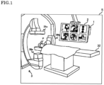
- FIG. 1 is a diagram that schematically shows the appearance of the image processing system S according to the embodiment.
- the image processing system S includes an image processing apparatus 1, a display device 2, and an X-ray imaging apparatus 3. An outline of the system will be described below with reference to Figure 1 .
- the X-ray imaging apparatus 3 is a device for capturing an X-ray image of a test subject P, who is a person in a state in which a device for examination or treatment of blood vessels (hereinafter simply described as "device") is inserted, and transmitting the X-ray image to the image processing apparatus 1.
- device a device for examination or treatment of blood vessels
- the X-ray imaging apparatus 3 is equipped with an X-ray irradiator 30 (a first X-ray irradiator 30a and a second X-ray irradiator 30b) for irradiating test subject P with X-rays, and an X-ray detector 31 for detecting the X-rays emitted by the X-ray irradiator 30 and a bed 32 for supporting the test subject P.
- an X-ray irradiator 30 a first X-ray irradiator 30a and a second X-ray irradiator 30b
- the images generated from X-rays detected by the X-ray detector 31 include the blood vessels (which can be seen by flowing a contrast medium) and tissues such as bones of the test subject P, as well as various types of devices used for blood vessel examination and treatment (for example, catheters such as guiding catheters, guide wires, embolic coils, delivery wires for transporting embolic coils to sites of interest, or such).
- the user can concentrate on the work in the area of interest (for example, guiding a microcatheter into an aneurysm, placing a coil into an aneurysm, expanding a balloon, placing a stent, or such).
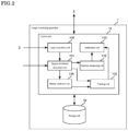
- FIG. 2 is a diagram that schematically shows a functional configuration of the image processing apparatus 1 according to the embodiment.
- the image processing apparatus 1 is equipped with a storage unit 10 and a control unit 11.
- the arrows indicate the main data flows, and there may be data flows that are not shown in Figure 2 .
- each functional block shows a configuration of the functional units, not a configuration of the hardware (device) units. Therefore, the functional blocks shown in Figure 2 may be mounted in a single device, or may be mounted separately in a plurality of devices. Data can be exchanged between functional blocks via any arbitrary means such as a data bus, a network, and a portable storage medium or such.
- the storage unit 10 is a large-capacity storage device such as a ROM (Read Only Memory) that stores the BIOS (Basic Input Output System) of the computer that realizes the image processing apparatus 1, a RAM (Random Access Memory) which is a work area of the image processing apparatus 1, an HDD (Hard Disk Drive) or SSD (Solid State Drive) that stores an OS (Operating System), an application program, and the various information referred to when the application program is executed.
- BIOS Basic Input Output System
- RAM Random Access Memory
- HDD Hard Disk Drive
- SSD Solid State Drive
- the control unit 11 is a processor or such as a CPU (Central Processing Unit) or GPU (Graphics Processing Unit) of the image processing apparatus 1, and functions as an image acquisition unit 110 by executing the program stored in a storage unit 10, a region of interest acquisition unit 111, a tracking unit 112, a notification unit 113, a marker detection unit 114, and a distance measuring unit 115.
- a CPU Central Processing Unit
- GPU Graphics Processing Unit
- the image acquisition unit 110 acquires an X-ray image created based on the absorption rate of X-rays, which includes at least the blood vessel of the test subject P and the device for examination or treatment in the blood vessel as a photographic subject.
- the X-ray image may include an aneurysm formed in a blood vessel of the test subject P, which is of interest to a healthcare professional, or a narrowed part or infarcted part of the blood vessel.
- the region of interest acquisition unit 111 acquires one or more regions including at least a portion of the device included in the X-ray image as the region of interest.
- the region of interest may be established as, for example, the tip of a guide wire (GW), the tip of a guiding catheter (GC), a catheter marker, a coil, etc., but multiple areas, for example, the tip of GC and GW, the tip of two GW and the tip of the GW and the coil may be simultaneously established as the multiple regions of interest.
- the region of interest may include blood vessels (vascular lesion areas such as cerebral aneurysms and stenosis) and bones.
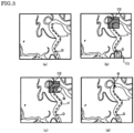
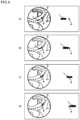
- Figures 3 (a)-(d) are diagrams for explaining the region of interest.
- Figure 3 (a) is a diagram that schematically demonstrates an example of an X-ray image obtained by imaging a blood vessel V.
- a guide wire which is one type of device D, is present in the blood vessel V.
- Figure 3 (b) is a diagram showing an example of a candidate region C which is a candidate region of interest.
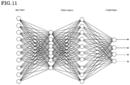
- the region of interest acquisition unit 111 may include a candidate region detector generated by using a known machine learning method such as a neural network ( Figure 11 ).
- the first candidate region C1 (tip of the guiding catheter) and the second candidate region C2 (tip of the guide wire) are shown as candidate regions of interest.
- This candidate region C is a result obtained by the region of interest acquisition unit 111 of inputting a frame image of an X-ray image to the candidate region detector.
- the candidate region detector is learned to detect the tip of a guide wire, the tip of a guiding catheter, a marker of a catheter, and the like.
- Detection generally means identifying the position or shape of an object in a single-frame still image in a video. For example, in the detection of the tip of a guide wire, since the guide wire is thin, it may be detected as point coordinates (x, y) on the screen. The detection of the entire guide wire can be done by detecting a bent thin thread-like shape as a one-dimensional curve or as a two-dimensional segmentation.
- the object detection algorithm that can be used in the candidate region detector, for example, algorithms such as Faster R-CNN, YOLO, SSD, U-Net, and ResNet can be used, but without being limited thereto. Further, in implementing the object recognition algorithm, for example, an image processing library such as OpenCV (Open Source Computer Vision Library) may be used.
- OpenCV Open Source Computer Vision Library
- Faster R-CNN is a CNN (Convolutional Neural Network) that simultaneously cuts out and recognizes regions.
- a convolutional neural network (CNN) is a neural network with many deep layers composed by piling up layers with some characteristic functions such as “convolutional layers” and “pooling layers", and it demonstrates excellent performance specifically in the field of image recognition.
- Faster R-CNN can cut out and recognize a region of interest from the input image in almost real time (about 10 to 20 frames per second).
- Faster R-CNN enables end-to-end learning from image input to object detection.
- YOLO You Only Look Once
- YOLO is also a CNN that simultaneously cuts out and recognizes regions.
- the entire image is divided into grids, and a Bounding Box is sought for each region.
- YOLO's CNN architecture enables detection of high-speed objects.
- SSD Single Shot MultiBox Detector
- Single Shot MultiBox Detector is also a CNN that cuts out and recognizes regions at the same time.
- SSD can output multi-scale detection frames from the output layers of various levels.
- SSD puts about 9000 rectangular frames called default boxes with different sizes and shapes on the image, and calculates the predicted value for each of the frames.
- SSD offers higher speeds by reducing the filter size.
- U-Net is a CNN that recognizes an object called segmentation pixel by pixel. It is composed of convolutional layers and has an almost symmetrical Encoder-Decoder configuration. The feature map downsampled through the pooling of the Encoder is upsampled by the Decoder.
- Figure 3(d) is a diagram showing a region of interest R set by the user.
- the region of interest R is shown as a black pentagon and is a region that includes the tip portion of the device D.
- Figure 3(d) only one region of interest R is set, but the user can set two or more regions of interest R.
- the tracking unit 112 tracks each one or more regions of interest R in the X-ray image.
- the tracking unit 112 can materialize tracking of the region of interest R by using a known image tracking technique.
- Known image tracking techniques include, but are not limited to, algorithms such as Boosting, MIL, TLD, MedianFlow, KCF, GOTURN, MOSSE, CSRT and the like.
- the tracking algorithm may be used in combination with the object detection algorithm described above. In implementing the algorithm, for example, a library such as OpenCV (Open Source Computer Vision Library) may be used.
- tracking the region of interest R also includes intermittently detecting the region of interest R and identifying its state.
- tracking of the region of interest R may be performed using a tracking algorithm or an object detection algorithm, or a combination thereof.
- the BOOSTING tracker is a tracker based on the online version of AdaBoost (an algorithm used internally by HAAR cascade-based face detector).
- AdaBoost an algorithm used internally by HAAR cascade-based face detector.
- This classifier is trained at run time using correct and incorrect examples of objects.
- the first bounding box identified by the user (or another object detection algorithm) is treated as a correct example of the object, and the image outside the bounding box is treated as the background.
- AdaBoost an algorithm used internally by HAAR cascade-based face detector
- the MIL tracker is based on the same concept as the BOOSTING tracker above.
- the big difference is that the current position of the object is not just considered as a correct example, but at a small neighborhood around the current position is investigated to generate some potential correct examples.
- a "bag" of correct and incorrect answers is specified.
- the group of images in the correct bag is not all correct examples. Only one image of the correct bag needs to be an example of the correct answer.
- the correct bag contains an image centered on the current position of the object and an image of a small neighborhood around it.
- the MIL tracker has high performance, does not drift as much as the BOOSTING tracker, and provides reasonable performance even in the event of partial occlusion (shielding).
- TLD means tracking/learning/detection.
- this tracker breaks down the long-term tracking task into three components: (short-term) tracking, learning, and detection.
- This tracker tracks objects frame by frame.
- the detector identifies all previously observed appearances and calibrates the tracker as necessary.
- the detector error is estimated by learning and updated to avoid occurrence of future errors.
- the output of this tracker tends to be somewhat unstable; for example, if there are other pedestrians in the scene when tracking a pedestrian, this tracker may temporarily track another walker different from the pedestrian to be tracked.
- the advantage is that it works best even under occlusion (shielding) across multiple frames.
- the disadvantage is that there are many false positives.
- the MEDIANFLOW tracker tracks an object both in the forward direction and backward direction in time and measures the discrepancy between these two trajectories. By minimizing this Forward/Backward error, it is possible to detect tracking failures with certainty and select a reliable trajectory in the video. This tracker performs best when the movement is predictable and small, and when there is no obstruction. Unlike other trackers that continue even when the tracking clearly fails, this tracker can recognize that the tracking has failed.
- the GOTURN tracker is an algorithm based on a convolutional neural network (CNN). This tracker is robust to changes of viewpoint, changes of lighting, and deformations, but may not handle shielding (occlusion) well.
- CNN convolutional neural network
- the MOSSE (Minimum Output Sum of Squared Error) tracker uses adaptive correlation for object tracking.
- the MOSSE tracker is robust to lighting, scale, pose changes, and non-rigid deformation.
- the tracker can also detect occlusions based on the peak-to-sidelobe ratio and resume tracking from where it left off when the object reappears.
- the MOSSE tracker also works at high frame rates (450 fps or above). The advantage is that it is very easy to implement, as accurately as other complex trackers, and much faster.
- the CSRT tracker uses spatial reliability maps for tracking.
- the CSRT tracker operates at a relatively low frame rate (25 fps), but provides higher accuracy for object tracking.
- the notification unit 113 notifies the user of the fact that if at least one of the regions of interest R satisfies the condition determined for each of the regions of interest. Specifically, the notification unit 113 notifies the user, for example, when at least one of the regions of interest R satisfies the condition defined for each of the regions of interest, by displaying a message indicating that fact on the display device 2 or by sounding a notification tone on the speaker of the image processing apparatus 1 not shown.
- the user wears a device equipped with a vibrating component such as a smartphone, the user may be notified by vibrating the vibration component.
- the type, amplitude, and frequency of the notification sound may be changed according to the conditions.
- the vibration may change the period and amplitude of the vibration according to the conditions.
- the user of the image processing apparatus 1 can have the image processing apparatus 1 track the behavior of the set region of interest R, allowing the user to concentrate on working in the area of interest.
- the notification unit 113 may color the region of interest with a color different from the color of the acquired image (X-ray image) and display the region of interest.
- angiographic images are monochrome, and therefore it is very difficult to recognize the device contained in the image.
- coloring the region of interest the device can be easily recognized and it will be possible to provide the user with more accurate information.
- the regions of interest may be colored using different colors.
- the user In blood vessel catheterization surgery, the user first passes a guiding catheter into the test subject P's blood vessel to the vicinity of the area of interest. Subsequently, the user performs observation (diagnosis) and treatment of the site of interest, for example, coil embolization of a cerebral aneurysm, through another device such as a guide wire, a delivery wire, or a balloon catheter in the guiding catheter.
- observation diagnosis
- treatment of the site of interest for example, coil embolization of a cerebral aneurysm
- another device such as a guide wire, a delivery wire, or a balloon catheter in the guiding catheter.
- a catheter is a device that is an elongated tube with a lumen. This catheter is passed through a blood vessel and guided into an aneurysm, for example, a coil is inserted through the lumen of the catheter, and the coil is inserted into the aneurysm to prevent rupture.
- the guiding catheter is slightly thick with a diameter of about 2-4 mm, and plays a role of connecting from the puncture site to the front of the target site.
- a smaller device is inserted into this guiding catheter and guided to the target site.
- the advantage of guiding catheters is that various devices can be carried via a guiding catheter from the puncture site of a blood vessel in the groin or arm to the vicinity of the target site, and thereby eliminates the need to check the passage one by one. As a result, for example, the treatment can be efficiently performed without moving the fixed screen.
- Some guiding catheters have a balloon at the tip (a guiding catheter attached with a balloon), which can stop the flow in the blood vessel and stabilize the guiding catheter.
- An intermediate catheter is placed in a guiding catheter and positioned at an area proximally to the target site where the blood vessel is thin, in order to deliver the thinner device to the target site.
- a plurality of intermediate catheters may be used (gradually become thinner).
- a microcatheter is the finest catheter, which is soft and can be inserted into thin blood vessels.
- a coil or stent is placed in this microcatheter and carried to the target site.
- An embolic material may also be flushed from the microcatheter.
- a balloon catheter has a balloon attached near the tip of a microcatheter, and the balloon is inflated near the target site.
- the coil is prevented from coming out of the aneurysm, the stenotic site is dilated, and the blood flow is stopped in the event of vascular perforation to stop bleeding.
- the balloon usually refers only to the balloon portion of the balloon catheter.
- a guide wire of an appropriate size is often used inside. In rare cases, they may be guided by placing them in the flow of blood.
- a guide wire is an elongated wire.
- guide wires are used to guide a soft catheter to a site of interest, by selecting a vascular bifurcation.
- delivery wires to carry stents and devices that have a balloon attached to the guide wire to stop blood flow.
- the term guide wire is defined in a broad sense to include them. The reason for this is that the tips of those guide wires can perforate blood vessels and cause serious complications. Since one of the purposes of the present disclosure is to support the prevention of such perforation of blood vessels by the tip of such a guide wire, any wire including a thin wire that has a possibility to cause vascular perforation at the tip is referred to as a guide wire.
- the blood vessel of the test subject P is present in the body of the test subject P, so that the user cannot directly observe the various devices inserted in the blood vessel. Therefore, as described above, the user can manipulate the device D while viewing the blood vessel V and device D (e.g., guiding catheter, guide wire, coil, catheter, balloon, stent, etc.) that are imaged in the X-ray image generated from X-rays transmitted through the test subject P's body.
- the blood vessel V and device D e.g., guiding catheter, guide wire, coil, catheter, balloon, stent, etc.
- the X-ray imaging apparatus 3 used in catheterization is a device for generating X-ray images of a specific region including the area of interest (e.g., aneurysm, stenosis site, or infarction site in need of treatment) inside the test subject P's body.
- the area of interest e.g., aneurysm, stenosis site, or infarction site in need of treatment
- the entirety of device D is not always captured in the X-ray image that can be observed by the user.
- the tip of a guide wire or the tip of a guiding catheter may disappear from the X-ray image because it is out of the angle of view of the X-ray image, and the user may be unable to observe it.
- a vascular perforation at the tip of the device may go unnoticed.
- Vascular perforation is a serious life-threatening complication.
- Vascular perforation is most likely to occur at the tip of a device, and it is most likely to occur especially at the tip of a guide wire or catheter. For this reason, the present disclosure focuses specifically on the tip.
- an example of the conditions established for the region of interest R used in the present disclosure is a condition related to the distance between the tip of the guiding catheter or the tip of the guide wire and the edge of the X-ray image.
- the condition may be set to be that the region of interest R exceeds a specific range specified on the X-ray image (for example, a boundary specified by the user with a pointing device such as a mouse) or simply that it moves. That is, in some embodiments of the present disclosure, not only the edge portion of the image but also the range of any arbitrary region in the image may be treated the same as the edge portion. Further, the boundary line may be a straight line, a curve, a circle, a rectangle, or any other polygon. In some embodiments of the present disclosure, the distance between the region of interest and the edge of a particular range may be displayed. The manner in which the distance is displayed may vary depending on the length of the distance between the region of interest and the edge of the specific range.
- the notification unit may notify the user on the condition that the value obtained by dividing the distance between the region of interest and the edge of the specific range by the movement speed of the region of interest in the image is less than a predetermined threshold value.
- Some embodiments of the present disclosure include a function to make it easier for the operator to make a decision by making a specific range easier to see by superimposed display or other means. The method of displaying the range may use arrows or such as well as superimposed display, but it is not limited thereto. Further, in some embodiments of the present disclosure, the distance may be determined by either a straight line distance or a distance along a blood vessel.
- the guide wire tip black portion
- the guide wire tip is recognized and the stored guide wire tip is superimposed on the subsequent X-ray image obtained in real time, as shown in the central figure in Figure 21 .
- this makes it easy to visualize and grasp how far the guide wire tip has moved since then.
- the image processing apparatus includes a storage unit that acquires and stores the position and/or shape of a device for examination or treatment in a blood vessel at any point in time, and has the function of superimposing the stored device position and/or shape on images since the acquisition.
- a notification can be issued if the tip of a guide wire attached to them or their tip moves out of a certain range specified by the surgeon or automatically.
- cerebral aneurysm embolization if the tip of the guide wire in the balloon catheter moves out of the specified range, there is a risk of the balloon slipping, not being returned and perforating the blood vessel at the distal region, and therefore a notification can be issued.
- a notification can be sent out because it may occlude an important blood vessel. If the coil deviates from the mask image (region) of the aneurysm, a notification can also be issued because of the possibility that the aneurysm may be perforated by the coil, guide wire, or catheter. While it is important that the guiding catheter remains stable for all endovascular procedures, there are times when it is desirable to correct the situation before it disappears outside of the frame, and a notification can be issued if it appears to be moving out of a certain area.
- embolization In tumor embolization, embolization of cerebral arteriovenous malformation, dural arteriovenous fistula embolization or such, embolization is performed using an embolization material such as liquid or particles, and if the embolization material exceeds the designated area, there is a possibility that it may cause a stroke in an important area, and a notification can be issued.
- the device may also include liquid embolic materials, particle embolic materials and such.
- care is taken in endovascular surgery to keep any arbitrary device, embolic material and such within a designated area and this can be supported.
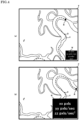
- Figures 4(a)-(b) illustrate an example of the conditions set for the region of interest R.
- the region of interest R is set at the tip portion of the device D.
- information W indicating the speed and acceleration of the region of interest R and the distance (in pixels) between the region of interest R and the edge area F of the X-ray image is superimposed on the X-ray image.
- Figure 4(a) shows an example when the device D is a guide wire.
- a specific region specified in the X-ray image may be considered the same as the edge area F of the X-ray image.
- the notification unit 113 notifies the user on the condition that the region of interest R disappears from the X-ray image, when a region including the tip portion of the guide wire is set as the region of interest R.
- the X-ray image is an image showing a fixed area that includes the region of interest. Usually, during the procedure, the area displayed as the X-ray image is fixed. Further, when a region including the tip portion of the guide wire is set as the region of interest R, the notification unit 113 notifies the user on the condition that the distance between the region of interest R and the edge area F of the X-ray image is less than a predetermined threshold distance.
- the "predetermined threshold distance” is a "reference distance for judgment of ejection" established for the notification unit 113 to judge whether or not there is a high probability that the tip of the device will be outside the angle of view of the X-ray image.
- the specific value of the predetermined threshold distance may be determined by experimentation, taking into consideration the frequency of notification by the notification unit 113 and usability, or such. For example, either the number of pixels in the vertical direction or the number of pixels in the horizontal direction of the X-ray image is 5% of the number of pixels in the other.
- region of interest R which is an area including the tip portion of a guiding catheter or the tip portion of a guide wire
- the size of movement of the device D in the blood vessel V can be a useful indicator for the user to predict the time it will take for the tip portion of the device D to reach the edge area F of the X-ray image. Specifically, the greater the speed or acceleration of the tip portion of D, the shorter the time until the tip portion of D reaches the edge area F of the X-ray image. Therefore, when a region including the tip portion of a guiding catheter or the tip portion of a guide wire is set as the region of interest R, the notification unit 113 may notify the user on the condition that at least either of the movement speed and the acceleration of the region of interest R in the X-ray image exceeds a predetermined threshold value. As a result, when the movement speed or acceleration of the region of interest R is greater than the threshold value, the user's attention can be drawn before the region of interest R approaches the edge area F of the X-ray image.
- the distance between the tip portion of the device D and the edge area F of the X-ray image in the blood vessel V is a useful indicator for the user to determine the probability of the tip portion of device D reaching the edge area F of the X-ray image. Therefore, as shown in the information W in Figure 4 , the notification unit 113 may display the distance between the region of interest R and the edge area F of the X-ray image on the display device 2 which displays the X-ray image.
- the distance between the region of interest R and the edge area F of the X-ray image may be the distance when the region of interest R moves to the edge area F of the X-ray image along the blood vessel V inserted with the device D in which the region of interest R is set.
- This can be achieved by the distance measuring unit 115, which extracts the blood vessel V using a blood vessel recognition engine generated in advance using a known machine learning method or the like, and measures the distance from the region of interest R to the edge area F along the blood vessel V.
- the distance measuring unit 115 may measure the distance described above based on the trajectory of the device D as it travels through the blood vessel V.
- the notification unit 113 may change the display mode of the distance according to the length of the distance between the region of interest R and the edge area F. For example, the font size may be increased as the distance becomes shorter, the color may be changed according to the distance (from blue to yellow to red), the region of interest may be enlarged according to the length of the distance, and the color or size of the mark attached to the region of interest may be changed according to the length of the distance.
- the region of interest R set at the tip portion of the device D is closer to the edge area F than in the example shown in Figure 4(a) . Therefore, the font of the information W, which indicates the speed and acceleration of the region of interest R and the distance (in pixels) between the region of interest R and the edge area F of the X-ray image, is greater than in the example shown in Figure 4(a) .
- the "distance between the region of interest R and the edge area F of the X-ray image” may be the shortest distance between the region of interest R and the edge area F of the X-ray image, or it may be the length measured along the direction of movement of the region of interest R to the edge area F of the X-ray image.
- the blood vessel extraction processing by the distance measuring unit 115 can be omitted, which is advantageous in that it can speed up the processing.
- the notification unit 113 may notify the user on the condition that the value obtained by dividing the distance between the region of interest R and the edge area F of the X-ray image by the movement speed of the region of interest R in the X-ray image is less than a predetermined threshold value.
- the value obtained by dividing the distance between the region of interest R and the edge area F of the X-ray image by the movement speed of the region of interest R in the X-ray image is, so to speak, the expected time until the region of interest R reaches the edge area F of the X-ray image.
- the value of the "predetermined threshold value” is the "grace period for judgment of ejection" established for the notification unit 113 to judge whether or not there is a high probability that the region of interest R will be outside the angle of view of the X-ray image.
- the specific value of the grace period may be determined by experimentation, taking into consideration the frequency of notification by the notification unit 113 and usability or such, and it is, for example, 3 seconds.
- Figure 5 shows an example of a message Ms notified by the notification unit 113.
- the notification unit 113 displays a message superimposed on the X-ray image indicating that the region of interest R will disappear out of the X-ray image in 3 seconds (so-called frame out).
- the notification unit 113 may change the shape of the region of interest R (changed to a circle in Figure 5 ), increase the size of the region of interest R, or change the color of the region of interest R when the region of interest R approaches the edge area F of the X-ray image. This allows the notification unit 113 to make it easier for the surgeon to recognize that the region of interest R is about to frame out.
- Figure 6 is a figure that illustrates another example of the conditions set for the region of interest R.
- Figure 6 shows an example where the device D is a guiding catheter.
- the guiding catheter differs in that not only its tip portion but also the entire device D can disappear from the X-ray image.
- the device D is a guiding catheter or a guide wire, it is the same in that the tip portion disappears from the X-ray image. Therefore, in the case of a guiding catheter, the region of interest R is set at the tip portion of the catheter as in the case of a guide wire.
- the threshold is determined based on the distance between the region of interest R and the edge area F of the X-ray image as the "predetermined threshold distance" mainly from the viewpoint of preventing frame-out of the surgical instrument.
- the threshold value can also be configured to issue a notification to the user when the distance moved in the region of interest R becomes greater than a predetermined threshold.
- the surgeon is looking at the stent and cannot follow the movement of the catheter tip with his eyes.
- the user can immediately notice the abnormality when the tip of the catheter is about to come out of the aneurysm.
- the threshold for the movement distance may be set after the region of interest (for example, the tip of the catheter) reaches a predetermined position (for example, within the aneurysm), based on the position reached.
- embolization in which an embolic coil is filled into the cerebral aneurysm is known.
- This treatment involves passing a guiding catheter to the vicinity of the cerebral aneurysm, which is the site of interest, passing the delivery wire of the embolic coil through the guiding catheter, and detaching and filling the embolic coil into the cerebral aneurysm. It is an operation aimed to block the inflow of blood into a cerebral aneurysm.
- Figures 7(a)-(b) schematically show an example of an X-ray image in which a guiding catheter that guides the delivery wire of the coil for embolization is imaged, and is a figure for illustrating another example of the conditions set for the region of interest R.
- the X-ray imaging apparatus 3 can irradiate the head of the test subject P with X-rays at different angles of incidence.
- Figures 7(a) and 7(b) illustrate examples of X-ray images taken by irradiating the head of test subject P with X-rays at different angles of incidence from each other. The user performs the embolization procedure while viewing the two images shown in Figures 7(a) and 7(b) .).
- the aneurysm is indicated by the symbol A.
- the user embolizes the aneurysm A by placing a plurality of embolic coils E inside the aneurysm A.
- the aneurysm A can be observed in the X-ray image shown in Figure 7(b) , the user focuses on one X-ray image among the two X-ray images.
- the delivery wire used to transport the embolic coil E to the aneurysm A is coupled to the embolic coil E at its tip, and the user performs a task of detaching the embolic coil E from the delivery wire after transporting the embolic coil E to the aneurysm A.
- the delivery wire of the embolic coil E is pre-equipped with a marker L to determine the timing for detaching the embolic coil E.
- the user uses the marker L on the delivery wire, rather than the embolic coil E itself in the X-ray image, as a landmark to determine the timing for detaching the embolic coil E.
- the user of the image processing apparatus 1 first sets the region of interest R in a portion of the guiding catheter that guides the delivery wire of the embolic coil E. Specifically, the user sets the region of interest R at a position where the marker L and the region of interest R overlap at the timing of detaching the embolic coil E from the delivery wire.
- the region of interest acquisition unit 111 receives the region of interest R set in a part of the guiding catheter that guides the delivery wire.
- the region of interest R can be designated using, for example, a pointing device such as a mouse, a touch panel, or the like.
- the region of interest R is indicated by a white star.
- the marker detection unit 114 detects the marker L that approaches the region of interest R among the markers L provided on the delivery wire of the embolic coil E for embolizing the aneurysm. Further, the tracking unit 112 tracks the marker L detected by the marker detection unit 114.
- the notification unit 113 notifies the user of the timing for cutting and detaching the embolic coil E from the delivery wire based on the positional relationship between the marker L and the region of interest R, triggered by the superimposition of the marker L and the region of interest R.
- Figures 8(a)-(d) are figures for illustrating the timing for detaching the embolic coil E.
- the device D shown in dashed lines in Figures 8(a)-(d) , is a delivery wire.
- the delivery wire is marked with a marker L at a certain section on the wire.
- Figures 8(a)-(d) show a general example of the marker L. In addition, it may be a single dotted line "- ⁇ -" or a long straight line.
- the marker L When the user moves the delivery wire, the marker L also moves in the X-ray image in conjunction with the movement of the delivery wire.
- the guiding catheter used to guide the delivery wire may move slightly due to friction or other reasons as the delivery wire moves, but the amount of movement is small compared to the movement of the delivery wire. Therefore, the user sets the region of interest R in advance at the position of the guiding catheter corresponding to the position where the marker L should be when the embolic coil E reaches the aneurysm A.
- the marker L is present over a certain section on the wire.
- the tip portion of the marker L comes into contact with the region of interest R, as shown in Figure 8(b) . This indicates that the embolic coil E has come close to the aneurysm A.
- the notification unit 113 takes the superimposition of the marker L and the region of interest R as a trigger to begin the action of notifying the user of the timing for cutting and detaching the embolic coil E from the delivery wire.
- the notification unit 113 causes the display device 2 to show information W2 indicating the distance that the marker L should travel before the embolic coil E is cut from the delivery wire, as triggered by the superimposition of the marker L and the region of interest R.
- the user sets the region of interest R so that the end portion of the marker L passes through the region of interest R just when the embolic coil E reaches the aneurysm A, as shown in Figure 8(d) .
- the information W2 displayed by the notification unit 113 on the display device 2 will show the distance until the end portion of the marker L passes through the region of interest R.
- the notification unit 113 When the marker L passes through the region of interest R, the notification unit 113 further notifies the user of this fact. This allows the user to notice the timing for detaching the embolic coil E from the delivery wire, even if the user is concentrating on the image of the aneurysm A taken as shown in Figure 7(b) .
- the notification unit 113 When a feature value indicating the shape of the device D included in the region of interest R satisfies a predetermined condition, the notification unit 113 notifies the user of the image processing apparatus 1 of this fact. Specifically, the notification unit 113 notifies based on the curvature of the device D included in the region of interest R or a feature value indicating the "deflection" of the device D included in the region of interest.
- the tip part of the device D is bent.
- elastic energy is accumulated in that portion.
- the elastic force of the device D can cause release of connection of the tip portion and the tip part may move at a higher speed. As a result, the tip portion of the device D may suddenly disappear from the X-ray image.
- the notification unit 113 notifies the user on the condition that the curvature of the device D included in the region of interest exceeds a predetermined threshold curvature or that the curvature is changing but the tip is not moving. It is also possible to take into account that the tip of device D is immobile or that the distance moved is lower than a certain threshold value.
- the "predetermined threshold curvature” is the "reference curvature for judgment of notification” established for the notification unit 113 to judge whether or not there is a high probability that the tip portion of the device D moves at a high speed.
- the specific value of the predetermined threshold curvature can be determined by experimentation, taking into consideration the frequency of notification by the notification unit 113, usability, material and size of the device D, elastic modulus, or such.
- Figures 9(a)-(c) are figures for illustrating conditions related to the shape of device D set in the region of interest R. Specifically, Figures 9(a)-(b) are figures for illustrating notifications based on the curvature of the device D.
- the region of interest R is indicated by a dashed circle.
- the region of interest R in Figure 9(a) is a circle with a radius of 1 cm centered at the tip portion of the device D.
- Figure 9(b) is a histogram showing the distribution of the curvature of the device D included in the region of interest R.
- Figure 9(b) shows the distribution of the radius of curvature of the device D in each small region by dividing the device D included in the region of interest R into multiple small regions and determining the radius of curvature of the device D in each small region.
- the notification unit 113 notifies the user on the condition that a feature value calculated from the distribution of the curvature (for example, a statistic such as an average value, a mode value, or a median value of the curvature) exceeds a predetermined threshold curvature or that the tip does not move despite a change in the curvature.
- a feature value calculated from the distribution of the curvature for example, a statistic such as an average value, a mode value, or a median value of the curvature
- the image processing apparatus 1 can provide a trigger for the user to notice the state in which the elastic force is accumulating in the device D.
- FIG. 9(c) is a schematic diagram showing the relationship between the length of the device D included in the region of interest R and the length of the center line of the blood vessel V included in the region of interest R.
- the device D and blood vessel are bent in the body of test subject P, for the convenience of explanation, the device D and blood vessel V are shown as straight lines in Figure 9(c) .
- the center line of the blood vessel V is shown as a single dotted line.
- the distance measuring unit 115 uses a blood vessel recognition engine to extract the blood vessel V in the region of interest R and track its center line to obtain its length D1. Similarly, the distance measuring unit 115 uses a device recognition engine generated using a known machine learning method or the like to extract the device D and obtain its length D2.
- the device D when a user advances a device D in a blood vessel V, the device D will meander along the wall of the blood vessel V. Therefore, the length D2 of the device D in the blood vessel V is longer than the length of the blood vessel V (length of the center line of the blood vessel V) D1, which means that the device D is deflected in the blood vessel V and elastic energy is accumulated in the device D. As the amount of this deflection increases, it is possible that some trigger will release the elastic energy and cause the device D to move significantly. As a result, the tip portion of the device D may disappear from the X-ray image.
- the differential length B which is the length D1 subtracted from the length D2 calculated by the distance measuring unit 115, can serve as an indicator of the amount of deflection of the device D in the blood vessel V. Therefore, the notification unit 113 displays the length B, which is the length D2 calculated by the distance measuring unit 115 minus the length D1, and if it is longer than the predetermined threshold length, it notifies the user of this fact. In this way, the image processing apparatus 1 can provide an opportunity for the user to notice that elastic force is accumulating in the device D.
- Aneurysm embolization catheters are marked with a tip marker (1st marker) and a 2nd marker (usually at a position 3 cm from the tip). It is important for the surgeon to know where the tip of the catheter is located within the aneurysm in order to perform the procedure safely. However, when the coil enters the aneurysm, the location of the tip marker becomes difficult to find and safety is reduced (see Figure 17 ). For example, if the tip marker moves deeper into the aneurysm, the tip, or the coil coming out of the tip, can perforate the aneurysm, leading to a serious complication of subarachnoid hemorrhage.
- the catheter or coil must be dislodged from the aneurysm and reinserted into the aneurysm, and this operation involves the risk of perforation of the aneurysm wall.
- FIG 17 the figure on the left shows the state in which the microcatheter is inserted into an aneurysm.
- the size of the aneurysm could be, for example, 10 mm.
- the distance between the 1st marker and 2nd marker attached to the microcatheter is constant (usually 30 mm). For example, suppose that the positions of the 1st marker and 2nd marker are recorded in this state, respectively (memorized position).
- the middle figure in Figure 17 shows the state in which the position of the microcatheter has moved. Once the coil enters the aneurysm, the position of the 1st marker becomes invisible or hard to see.
- the position of the 1st marker is estimated from the difference between the position of the 2nd marker at this point and the previously stored position of the 2nd marker.
- the 1st marker is predicted to be at a place approximately 0 mm from the aneurysm neck (predicted position A).
- the figure on the right also shows the state in which the position of the microcatheter moved.
- the position of the 1st marker is estimated based on the distance moved by the 2nd marker. In this case, it is estimated to be 8 mm from the aneurysm neck.
- Some embodiments of the present disclosure relate to a method for estimating the tip position from the movement of the 2nd marker when the tip of the catheter is in the coil (aneurysm) and its position is unknown. More specifically, it relates to a method for estimating the tip position of a catheter, comprising a step of storing the positional relationship between the tip of the catheter and the 2nd marker (for example, 3 cm apart), a step of storing the distance a between the neckline of the aneurysm and the 1st marker and the position of the 2nd marker at that time t1, a step of calculating the distance b of movement from the position of the 2nd marker at time t2, and a step of estimating the distance a-b from the aneurysm neckline to the tip of the catheter, and a step of notifying the user of the estimated distance.
- the catheter tip, 2nd marker, and aneurysm neckline can be automatically detected by image recognition by a computer. Alternatively, they can be specified manually by a pointing device such as a mouse or a touch panel.
- the estimated distance a-b can be displayed on a display device.
- the position of the catheter tip, estimated based on the estimated distance a-b may be displayed on the display device.
- An arbitrary threshold value may be set and notified when the distance deviates from it, and the speed and acceleration may be determined in addition to the distance and notified according to the value (rapid or large movements are likely to be dangerous).
- the distance moved can be a straight line or a distance along the curve of the catheter.
- the distances a, b, and a-b can be probability distributions due to changes in the shape of the catheter. For example, if there are multiple timings to be memorized first, a distribution of the distance a can be made, so the mean and variance can be used to guess the location and predict it as the most likely single point, or it can be displayed as a probability distribution in a heat map or the like.
- the estimated distance may be expressed by a probability distribution, and the estimated position of the catheter tip may be colored like a heat map and displayed based on the probability distribution.
- the position of the 2nd marker may be specified by the surgeon or recognized by the computer, and the position may be indicated on the display device in a semi-transparent superimposition display or by an arrow.
- the surgeon/assistant visually recognizes whether the tip marker has moved forward or backward by recognizing how much the current 2nd marker has shifted from this fixed display.
- Some embodiments of the present disclosure relate to programs for executing the above methods on a computer. Further, some embodiments of the present disclosure also relate to an image processing apparatus and a method of operating the same for performing the above methods.
- Such an image processing apparatus may include, for example, a positional storage unit that stores the positional relationship between the tip of the catheter and the 2nd marker (for example, 3 cm apart), a positional storage unit that stores the distance a between the neckline of the aneurysm and the 1st marker and the position of the 2nd marker at that time t1, a distance estimation unit that calculates the distance moved b from the position of the 2nd marker at time t2 and estimates the distance a-b from the aneurysm neckline to the tip of the catheter, and a notification unit that notifies the user of the estimated distance.
- some embodiments of the present disclosure also relate to a cerebral aneurysm coil embolization assistance system that is equipped with the image processing apparatus described above and an image capture device that captures X-ray images of a patient (or test subject P) in the state in which a guiding catheter and a delivery wire for an embolization coil are inserted into a vessel, and transmits the images to the above image processing apparatus.
- Figure 22 is a flowchart for explaining the flow of estimation processing of the catheter tip position using the 2nd marker, which is performed by the image processing apparatus according to the embodiment.
- the processing in this flowchart is started, for example, when the image processing apparatus 1 is started, or when the user or the image processing apparatus 1 determines that the processing needs to be started.
- the line of the aneurysm neck is then determined automatically or by designation of the user (surgeon) (S104). Then, the distance A between the line of the aneurysm neck and the 1st marker is calculated (S106). At this time, the straight line or curved line distance A between the line of the aneurysm neck and the 1st marker (usually located within the aneurysm) can be measured.
- the 2nd marker is continuously tracked and the distance moved b is measured (S108).
- the distance of the 1st marker from the aneurysm neck is estimated (S110).
- the distance of the 1st marker from the aneurysm neck is estimated to be A-b.
- the estimated position of the 1st marker is then displayed (S112).
- the guide wire tip it is desirable to obtain information on the details of the movement of the tip portion. For example, rapid and large movements increase the risk of vascular perforation.
- the disappearance of a guiding catheter it is desirable to obtain information on the position and elapsed time at the time of the catheter's exit from the image.
- a coil detector it is desirable to obtain information on the deviation from the optimal point.
- the image processing apparatus is equipped with a function (i.e., replay function) that allows the surgeon to save the image and recognition information and review it when necessary by providing the information as needed.
- Figure 12 shows the configuration of an image processing apparatus further equipped with an image recording unit (which can be integrated with 10) that stores the images obtained from the image acquisition unit 110 and an image extraction unit that extracts some of the images before and after the time the notification occurred.
- Figure 13 shows an example of an enlarged display of the replay image at the time the notification occurred, with the region of interest being cropped out at the center.
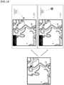
- Figure 14 shows an example of a (an enlarged) replay playback window on the real-time display screen. In this example, the replay is enlarged and displayed in an area as far out of the region of interest as possible, which allows one to determine what happened in the area where the warning was issued within the limited area of one screen.
- the image processing apparatus further comprises an image recording unit that stores images (including videos) obtained from the image acquisition unit over time (continuously).
- the image processing apparatus further comprises an image extraction unit that extracts video images from the image storage unit for a certain period of time before and after the notification was issued by the notification unit.
- the extraction period and playback speed of the images may be automatically determined based on at least one of the movement distance, movement speed, and acceleration of the region of interest when the notification occurred.
- the information obtained by the region of interest acquisition unit, the tracking unit, the notification unit, the marker detection unit, and/or the distance measuring unit can also be used in the extraction processing.
- the image processing apparatus can display the extracted image on a display device.
- the extracted image may be automatically displayed a predetermined number of times repeatedly.
- the extracted image may be displayed based on any arbitrary operation including playback, stop, fast forward, rewind, frame advance, slow playback, and double-speed playback. This allows the user to easily check the images.
- the time elapsed from the time when the notification occurred, a comparison of the position of the region of interest at the time when the notification occurred and after any arbitrary elapsed time (the comparison display may include, for example, the relevant area, differences in the detected position, and the alignment of the images themselves), or the trajectory of the region of interest obtained by the tracking unit may be superimposed on the extracted image and further displayed on the display device.
- the image processing apparatus can cut out a portion of an area in the vicinity of the region of interest from the extracted image and display it.
- the extracted image can be displayed in a position that does not interfere with the display of the region of interest.
- the extracted image may be enlarged and displayed.
- the image processing apparatus can display the extracted image simultaneously with the occurrence of the notification or after a predetermined time has elapsed from the occurrence of the notification. In some embodiments of the present disclosure, the image processing apparatus can simultaneously display the video images taken from multiple directions.
- the replay display described above may be used at a time other than at the time of occurrence of the notification.
- the image extraction unit may extract images from the image storage unit not only for a certain period of time before and after the notification is issued by the notification unit, but also for any time or period of time. For example, when the user (surgeon) feels the need to do so, he can specify any arbitrary region of interest to view a replay display of the previous scene. This allows the user to grasp and compare what happened in the region of interest while viewing the display in real time.
- Some embodiments of the present disclosure relate to a program for executing the above method on a computer. Further, some embodiments of the present disclosure also relate to an image processing apparatus and a method of operating the same for executing the above methods.
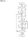
- FIG 23 is a flowchart for explaining the flow of processing of the replay function performed by the image processing apparatus according to the embodiment. Processing in this flowchart starts, for example, when the image processing apparatus 1 is started.
- the image acquisition unit 110, region of interest acquisition unit 111, and tracking unit 112 function to detect and track the device D for examination or treatment in the blood vessel V by video analysis (S202).
- a notification condition (the distance moved exceeds a threshold value, or such) is met (S204); and if the condition is met, along with the issuance of a notification, a portion of the display screen shows the replay videos before and after the notification condition is met (S206).
- the real-time image is displayed as usual, and the replay video may be repeated and displayed several times so that it does not overlap with the area meeting the notification condition, or until the user (surgeon/assistant) wishes (S208).
- the replay video screen is closed. After completion, the processing in this flowchart may be started again.
- the region of interest such as the tip of a guide wire or the tip of a guiding catheter
- the level of risk depends on the amount of movement.
- the tip of the guide wire is slightly (within 5 mm or such) outside the frame, the possibility of vascular perforation is low, but if the tip is significantly outside the frame (20 mm or more, or such), the risk of vascular perforation is high, and when the region of interest is framed out, it is necessary to pull it back within the angle of view of the X-ray image, but it may not be possible to deal with it immediately depending on the situation.
- some embodiments of the present disclosure relate to a device for estimating and displaying the position, speed, and acceleration status of a framed-out region of interest.
- an image processing apparatus which is an image processing apparatus comprising an image acquisition unit for acquiring an image including at least a device for examination or treatment in a blood vessel as a photographic subject, a region of interest acquisition unit for acquiring one or more regions in the image that include at least a portion of the device as a region of interest, a tracking unit that tracks each of the regions of interest in the image, and a notification unit that notifies the user of the image processing apparatus when a region including the tip portion of a catheter or the tip portion of a guide wire is set as the region of interest, on the condition that the region of interest disappears from the image, and a status estimation unit that estimates the current position and/or speed of the tip portion of the catheter or the tip portion of the guide wire based on the position, speed and/or acceleration of the tip portion of the catheter or the tip portion of the guide wire immediately before the region of interest disappears from the image ( Figure 15 ).
- the status estimation unit can store the output from the region-of-interest acquisition unit, marker detection unit, and tracking unit chronologically from before the frame-out to estimate the position of the framed-out region-of-interest, and use the stored output to calculate the position, speed, acceleration, and other states of the region-of-interest.
- the region of interest frames out and tracking on the screen becomes impossible, the position, speed or such of the region of interest is estimated from the state prior to the frame-out and the user is notified.
- Estimation methods for this include, but are not limited to, learning-based methods using deep learning (CNN, RNN, WaveNet, or such) and Bayesian estimation methods (Kalman filter, extended Kalman filter, ensemble Kalman filter, particle filter, or such).
- some embodiments of the present disclosure relate to a device that calculates the level of risk from the estimated state and issues a notification to the user according to the level of risk.
- the position, speed, and risk level of the region of interest estimated by the status estimation unit can be displayed on a display device.
- the display method can be, but is not limited to, display by a point, an arrow, or a heat map.
- the position of the estimated region of interest is more than a predetermined distance from the edge of the image, it can be determined to be at high risk ( Figure 16 ).
- Figure 16 the position of the estimated region of interest is indicated by a circle, and the further away from the edge of the screen the position is estimated to be, the higher the level of risk is judged to be.
- the risk level may be indicated by the color of the circle (for example, green is low risk level and red is high risk level). If the calculated level of risk exceeds a certain threshold, an alert can be displayed on the screen of the display device. Or, an audio notification may be provided in addition.
- an image processing apparatus which is an image processing apparatus comprising an image acquisition unit for acquiring an image including at least a device for examination or treatment in a blood vessel as a photographic subject, a region of interest acquisition unit for acquiring one or more regions in the image that include at least a portion of the device as a region of interest, a tracking unit that tracks each of the regions of interest in the image, and a notification unit that notifies the user of the image processing apparatus when a region including the tip portion of a catheter or the tip portion of a guide wire is set as the region of interest, on the condition that the region of interest disappears from the image, and a status estimation unit that estimates the current position and/or speed of the tip portion of the catheter or the tip portion of the guide wire based on the position, speed and/or speed of the tip portion of the catheter or the tip portion of the guide wire immediately before the region of interest disappears from the image, wherein a warning is issued to the user when the current position and/or speed of the region of interest estimated
- Some embodiments of the present disclosure relate to a program for executing the above method on a computer. Some embodiments of the present disclosure also relate to an image processing apparatus for executing the above methods and a method for operating the same.
- Figure 24 is a flowchart for explaining the processing flow of estimating the position of the region of interest outside the frame, which is executed by the image processing apparatus according to the embodiment.
- the processing in this flowchart starts, for example, when the image processing apparatus 1 is started.
- the image acquisition unit 110, region of interest acquisition unit 111, and tracking unit 112 function to detect and track the device D for examination or treatment in the blood vessel V by video analysis (S302).
- the location of the device outside the frame is estimated (S306).
- the position of the device D outside the frame is inferred from the front side of the black part of the guide wire, filter, balloon, or such, which is visible on the screen connected to the device D.
- the estimation can be done by using the difference in distance, machine learning, or such.
- the estimated position of the device is displayed (S308).
- the estimated position of the device D outside the frame is displayed on the display screen as the actual estimated position or distance from the frame. The further out of the frame, the stronger the display or notification may be.
- the results of image analysis can be displayed on two screens of different sizes.
- endovascular surgery is generally performed while viewing multiple screens (for example, four screens), and the surgeon can grasp three-dimensional information by viewing at least two screens (generally, frontal (AP or F direction: Anterior-Posterior, Frontal) and lateral (RL or LAT direction: Right to Left, Lateral). Therefore, it is important to display both frontal and lateral images, and it is very important to display them in an easily viewable manner on a monitor of limited physical size.
- monitors are often placed over the patient's bed at a distance of 1 m or more, and instructions are often given to bring the monitor as close as 1 cm to the surgeon.
- the two screens of different sizes can be switched automatically or by selection of the user (surgeon) (see Figure 18 ). Since there are physical limits to the screen size and one may want to see one of the screens larger than the other, visibility can be improved by displaying the two screens in different sizes, as shown in Figure 18 .
- the screen to be notified can be recognized by the user by making the frame portion of the screen glow, changing the color, or highlighting the screen (see Figure 19 ).
- notifications with colored frames or such make it easier for the user to know which screen to pay attention to. If the notification is issued on the side of the smaller screen, the two screens may be automatically switched (thereby switching the area of attention to a larger, easier-to-see screen).
- the display device may be equipped with a function to alert the user by making the frame portion of one of the two screens glow, changing the color, or highlighting the screen.
- the region of interest in the screen is output as a probability distribution, so the presence of the region of interest can be expressed in terms of probability.
- the probability distribution of the region of interest that exists can be displayed as a numerical value, color, bar, or such.
- the probability distribution may be converted and displayed in a way that is easy to understand. For example, 0-30% may be displayed as low, 30-70% as middle, and 70-100% as high in text or displayed in three colors. As another example, the area below 70% may be slightly darkened so that the region of interest or the region to be notified appears bright like a spotlight.
- the notification unit can display an image on a display device by a numerical value, color, bar or heat map according to the probability that at least one of the regions of interest satisfies a condition defined for each of the regions of interest, or a numerical value, color, bar or heat map based on any transformation applied to the probability distribution.
- the notification unit can color the region of interest with a color or heat map according to the probability that at least one of the regions of interest satisfies a condition defined for each of the regions of interest, or with a color or heat map based on an arbitrarily transformed value of the probability distribution, and display it on the display device displaying the image.
- it can also replace the probability that satisfies a condition with a numerical value or color and display it on the display device displaying the image.
- a database of the lineup and standards of devices currently available in the country should be created. Inventory information at each facility can also be included. A system that displays this information on a monitor is built. For example, when a microcatheter is selected, the available microcatheter lineups, standards, inventory information and such are listed up and displayed. As additional information, it is also possible to search information on whether the guiding catheter can accommodate that device or multiple devices. For example, if the lumen of a guiding catheter is R and the outer diameters of two devices are r1 and r2, the two devices will fit inside the guiding catheter if R > r1+r2. The same idea can be applied to one device or three or more devices.
- the choice of coil lineups is based on the size of the aneurysm and the behavior of the previously placed coil.
- lineup candidates can include preferences based on the facility and surgeon (user).
- Suggestions can be made based on the aneurysm or coil winding method based on image analysis.
- the surgeon selects the desired device from such a list and performs the surgery. This information is recorded and can be used to automatically create a surgical record, for example, in combination with snapshots of the treatment video.
- the display device that displays the image can display a product list of devices (for example, various types of catheters and coils) for examination or treatment in the blood vessel (see Figure 20 ). Further, the display device may also display a product list narrowed down by size or inventory. In addition, the display device may show a list of recommended products based on results of image analysis, facility information, or user preference information.
- a product list of devices for example, various types of catheters and coils
- the display device may also display a product list narrowed down by size or inventory.
- the display device may show a list of recommended products based on results of image analysis, facility information, or user preference information.
- the image processing apparatus may automatically or based on the user selection create a surgical record that includes information about the device used, the images acquired, and the image analysis results.
- some embodiments of the present disclosure also relate to a system, which is an endovascular surgical support system that includes a storage unit which stores a product list of devices (for example, various catheters and coils) for examination or treatment in a blood vessel, a recommendation unit that recommends products for use based on image analysis results, facility information, or user preference information, and a display unit that displays the recommended products.
- a storage unit which stores a product list of devices (for example, various catheters and coils) for examination or treatment in a blood vessel
- a recommendation unit that recommends products for use based on image analysis results, facility information, or user preference information
- a display unit that displays the recommended products.
- vascular catheterization support systems for example, catheterization support systems for cerebral, cardiac, peripheral limbs, and abdominal vessels, in particular, cerebral blood vessels.
- a system is a system that can comprise an image processing apparatus and an image capture device that captures and transmits to the image processing apparatus X-ray images of a patient with one or more devices inserted into a blood vessel, wherein the image processing apparatus is equipped with an image acquisition unit that acquires X-ray images over time of a region (for example, a fixed region) that includes at least an area of interest for achieving a surgical objective and a device inserted into a blood vessel, a region of interest acquisition unit that acquires one or more regions which include at least a portion of the device included in the image as a region of interest, a tracking unit that tracks each of the regions of interest in the image, and a notification unit that notifies a user of the image processing apparatus when at least one of the regions of interest meets a condition defined for each of the regions of interest, wherein one or more of
- the notification unit may display the distance between the region of interest and the edge of the image or the distance between the marker and the region of interest on a display device that displays the image, and the notification unit can change the manner in which the distance is displayed on the display device according to the length of the distance, and the change in the display mode may include changing the font, size, or color of the characters displayed according to the length of the distance, changing the color of the entire screen or a portion of the screen of the display device according to the length of the distance, displaying a graphic on the entire screen or outside the frame of the display device or in a part of the screen, enlarging and displaying the region of interest according to the length of the distance, or changing the color or size of the mark attached to the region of interest according to the length of the distance.
- the notification unit may also sound a notification tone in accordance with the length of the distance.
- the distance may be determined by either a straight line distance or a distance along a blood vessel.
- an aneurysm coil embolization assistance system in particular, a cerebral aneurysm coil embolization assistance system.
- a cerebral aneurysm coil embolization assistance system is a system that can be equipped with an image processing apparatus and an image capture device that captures and transmits to the image processing apparatus X-ray images of a patient in a state with a guiding catheter and a delivery wire for an embolic coil inserted into a blood vessel, wherein the image processing apparatus is equipped with an image acquisition unit that acquires X-ray images over time of a fixed area that includes at least the aneurysm in the patient's blood vessel, a catheter inserted into the blood vessel and a delivery wire for an embolization coil, a region of interest acquisition unit that acquires one or more areas that include at least a portion of the guiding catheter in the images as a region of interest, a marker detection unit that detects a marker provided on the delivery wire, which is a marker that approaches one or more regions of interest set in a
- the notification unit may display the distance between the region of interest and the edge of the image or the distance between the marker and the region of interest on a display device that displays the image, and the notification unit can change the manner in which the distance is displayed on the display device according to the length of the distance, and the change in the display mode may include changing the font, size, or color of the characters displayed according to the length of the distance, changing the color of the entire screen or a portion of the screen of the display device according to the length of the distance, displaying a graphic on the entire screen or outside the frame of the display device or in a part of the screen, enlarging and displaying the region of interest according to the length of the distance, or changing the color or size of the mark attached to the region of interest according to the length of the distance.
- the notification unit may also sound a notification tone in accordance with the length of the distance.
- the distance may be determined by either a straight line distance or a distance along a blood vessel.
- FIG 10 is a flowchart illustrating the flow of the image analysis processing performed by the image processing apparatus 1.
- the processing in this flowchart starts, for example, when the image processing apparatus 1 is started.
- the image acquisition unit 110 acquires an X-ray image created based on the absorption rate of X-rays, which includes at least a blood vessel V and a device D for examination or treatment in the blood vessel V as a photographic subject (S2).
- the region-of-interest acquisition unit 111 acquires one or more regions including at least a portion of the device D in the X-ray image as the region-of-interest R (S4).
- the tracking unit 112 tracks each of the regions of interest R in the X-ray image (S6). If at least one of the regions of interest R satisfies a condition defined for each of the regions of interest R (Yes in S8), the notification unit 113 notifies the user of the image processing apparatus 1 of that fact (S10). If all the regions of interest R fail to satisfy the defined condition (No in S8), the notification unit 113 skips the notification processing.
- step S12 the image processing apparatus 1 returns to step S6 and repeats the processing from step S6 to step S10.
- the processing in this flowchart is terminated.
- some embodiments of the present disclosure relate to an image diagnosis device that points out lesions or sites of lesion including, without limitations thereto, cerebral aneurysm, stenosis, occlusion, thrombus formation, vascular perforation (spillage of the contrast medium), shunt disease, nutrient vessel and tumor thickening of tumor vessels, venous thrombosis, avascular area of the capillary phase (finding of vascular occlusion), collateral circulation, and such, as determined by deep learning and other methods used in contrast-enhanced angiography.
- the image processing apparatus can further comprise a lesion recognition unit that recognizes a lesion selected from the group consisting of aneurysm, stenosis, vasospasm, dissection, occlusion, recanalization, thrombosis, site of thrombus and location of both ends, vascular perforation, leakage of contrast medium out of a blood vessel, calcification of a blood vessel, arteriosclerosis, shunt disease and its feeding and draining vessels, blood (contrast medium) backflow, and cerebral arteriovenous malformations, dural arteriovenous fistulas, avascular region, characteristics anatomy of bone (internal auditory canal, ocular fundus, supraorbital margin, pyramidal body, foramen magnum occipitalis, cervical spine, clavicle, rib and spine numbers, femoral head, pelvis), feeding vessels of tumor and tumor staining, venous occlusion, venous sinus
- the system may not go so far as to point out the lesion, but may notify when an abnormal finding is suspected, or point out which areas in the region may be abnormal. In such cases, the physician can make the final decision.
- some embodiments of the present disclosure relate to an image diagnosis device that points out changes in performing imaging of a blood vessel, when comparing with the previous imaging or imaging performed on a different day.
- the image processing apparatus can further comprise an image recognition unit that compares the angiographic image in the image with a previously acquired and stored angiographic image and notifies the change.
- the image processing apparatus 1 can provide technology to support judgment of the area of interest in catheter examination or treatment of blood vessels by allowing the user, a medical professional, to concentrate on the work in the area of interest.
- the examination and treatment of cerebral blood vessels were mainly described.
- the applicable subject of the present invention is not limited to the cerebrovascular system, but can be applied to examination and treatment of blood vessels including the circulatory system such as the heart, peripheral limbs, abdomen and such.
- the imaging apparatus 3 captures images of the surgical site of the test subject P.
- the imaging apparatus for capturing images of the test subject P's surgical site is not limited to the X-ray imaging apparatus 3.
- Other modalities such as MRI (Magnetic Resonance Imaging) and ultrasonography may also be used to capture images of the surgical site.
Landscapes
- Engineering & Computer Science (AREA)
- Health & Medical Sciences (AREA)
- Life Sciences & Earth Sciences (AREA)
- Medical Informatics (AREA)
- Physics & Mathematics (AREA)
- Nuclear Medicine, Radiotherapy & Molecular Imaging (AREA)
- General Health & Medical Sciences (AREA)
- Surgery (AREA)
- Radiology & Medical Imaging (AREA)
- Public Health (AREA)
- Heart & Thoracic Surgery (AREA)
- Molecular Biology (AREA)
- Animal Behavior & Ethology (AREA)
- Biomedical Technology (AREA)
- Veterinary Medicine (AREA)
- Pathology (AREA)
- Biophysics (AREA)
- Optics & Photonics (AREA)
- High Energy & Nuclear Physics (AREA)
- General Physics & Mathematics (AREA)
- Theoretical Computer Science (AREA)
- Human Computer Interaction (AREA)
- Computer Vision & Pattern Recognition (AREA)
- Multimedia (AREA)
- Oral & Maxillofacial Surgery (AREA)
- Quality & Reliability (AREA)
- Geometry (AREA)
- Primary Health Care (AREA)
- Epidemiology (AREA)
- Gynecology & Obstetrics (AREA)
- Robotics (AREA)
- Vascular Medicine (AREA)
- Dentistry (AREA)
- Apparatus For Radiation Diagnosis (AREA)
- Cameras In General (AREA)
- Transforming Light Signals Into Electric Signals (AREA)
Claims (19)
- Bildverarbeitungsvorrichtung zum Unterstützen einer vaskulären Katheterisierung, umfassend:eine Bilderfassungseinheit (110), welche dazu eingerichtet ist, ein Bild zu erfassen, welches wenigstens eine Vorrichtung zur Untersuchung oder Behandlung in einem Blutgefäß als ein fotografisches Subjekt enthält,eine Erfassungseinheit (111) für einen Bereich von Interesse, welche dazu eingerichtet ist, einen oder mehrere Bereiche in dem Bild, welche wenigstens einen Abschnitt der Vorrichtung enthalten, als Bereiche von Interesse zu erfassen,eine Nachverfolgungseinheit (112), welche dazu eingerichtet ist, jeden der Bereiche von Interesse in dem Bild nachzuverfolgen, undeine Benachrichtigungseinheit (113), welche dazu eingerichtet ist, einen Benutzer der Bildverarbeitungsvorrichtung zu benachrichtigen, wenn wenigstens einer der Bereiche von Interesse eine für jeden der Bereiche von Interesse bestimmte Bedingung erfüllt,wobei die Bilderfassungseinheit (110) dazu eingerichtet ist, Röntgenbilder im Laufe der Zeit eines fixierten Bereichs zu erfassen, welcher wenigstens einen Bereich von Interesse zum Erreichen eines Operationsziels einer vaskulären Katheterisierung und die in das Blutgefäß eingeführte Vorrichtung enthält, unddie Benachrichtigungseinheit (113) dazu eingerichtet ist, den Benutzer über die Bedingung, dass der Abstand zwischen dem Bereich von Interesse und einem Rand des Bilds kleiner ist als ein vorbestimmter Schwellenabstand, oder über die Bedingung zu benachrichtigen, dass ein Bereich von Interesse einen auf dem Bild spezifizierten spezifischen Bereich überschreitet.
- Bildverarbeitungsvorrichtung nach Anspruch 1, wobei der Bereich von Interesse als ein Bereich eingestellt sein kann, welcher einen Spitzenabschnitt eines Katheters oder den Spitzenabschnitt eines Führungsdrahts, einen Filter, einen Ballon, ein flüssiges embolisches Material, eine Spirale, einen Marker eines Katheters oder einen Marker eines Zuführdrahts der Spirale enthält.
- Bildverarbeitungsvorrichtung nach Anspruch 1 oder 2, wobei die Benachrichtigungseinheit (113):i) dazu eingerichtet ist, den Abstand zwischen dem Bereich von Interesse und dem Randabschnitt des Bilds auf einer Anzeigevorrichtung zum Anzeigen des Bilds anzuzeigen, und/oderii) dazu eingerichtet ist, den Anzeigemodus des Abstands in der Anzeigevorrichtung gemäß der Länge des Abstands zwischen dem Bereich von Interesse und dem Randabschnitt des Bilds zu ändern.
- Bildverarbeitungsvorrichtung nach einem der Ansprüche 1-3, wobei, wenn ein Merkmalswert, welcher eine Form der in dem Bereich von Interesse enthaltenen Vorrichtung angibt, eine vorbestimmte Bedingung erfüllt, die Benachrichtigungseinheit (113) dazu eingerichtet ist, über diese Tatsache zu benachrichtigen,wobei der Merkmalswert eine Krümmung ist undwobei die Benachrichtigungseinheit (113) dazu eingerichtet ist, über die Bedingung zu benachrichtigen, dass die Krümmung der in dem Bereich von Interesse enthaltenen Vorrichtung eine vorbestimmte Schwellenkrümmung überschreitet oder dass sich die Krümmung ändert aber sich die Spitze nicht bewegt.
- Bildverarbeitungsvorrichtung nach einem der Ansprüche 1-4, wobei die Benachrichtigungseinheit (113) dazu eingerichtet ist, über die Bedingung zu benachrichtigen, dass die Länge der Vorrichtung in dem Bild oder dem Bereich von Interesse minus die Länge der Mittellinie des Blutgefäßes in dem Bild oder dem Bereich von Interesse eine vorbestimmte Schwellenlänge überschreitet.
- Bildverarbeitungsvorrichtung nach einem der Ansprüche 1-5, wobei die Benachrichtigungseinheit (113) dazu eingerichtet ist, durch ein Einfärben des Bereichs von Interesse mit einer von dem Bild verschiedenen Farbe, ein Ändern der Schriftart, der Größe oder der Farbe der angezeigten Zeichen, ein Ändern der Farbe des gesamten Bildschirms oder eines Teils des Bildschirms der Anzeigevorrichtung, ein Anzeigen einer Grafik auf dem gesamten Bildschirm, außerhalb des Rahmens oder an irgendeiner anderen Stelle der Anzeigevorrichtung, ein Vergrößern des Bereichs von Interesse oder ein Ändern der Farbe oder der Größe einer an dem Bereich von Interesse angehefteten Markierung zu benachrichtigen.
- Bildverarbeitungsvorrichtung nach einem der Ansprüche 1-6, wobei die Benachrichtigungseinheit (113) ferner dazu eingerichtet ist, über die Bedingung zu benachrichtigen, dass:i) sich der Bereich von Interesse bewegt hat;ii) der Bereich von Interesse aus dem Bild verschwindet;iii) wenigstens eines aus dem Bewegungsabstand, der Bewegungsgeschwindigkeit und der Beschleunigung des Bereichs von Interesse in dem Bild einen vorbestimmten Schwellenwert überschreitet;iv) der durch ein Teilen des Abstands zwischen dem Bereich von Interesse und dem Rand des Bilds durch die Bewegungsgeschwindigkeit des Bereichs von Interesse in dem Bild erhaltene Wert kleiner ist als ein vorbestimmter Schwellenwert; oderv) der Merkmalswert, welcher die Form der in dem Bereich von Interesse enthaltenen Vorrichtung angibt, eine vorbestimmte Bedingung erfüllt.
- Bildverarbeitungsvorrichtung nach einem der Ansprüche 1-7, ferner umfassend:eine Bildspeichereinheit, welche dazu eingerichtet ist, im Laufe der Zeit von der Bilderfassungseinheit (110) erhaltene Bilder oder Videos zu speichern; undeine Bildextraktionseinheit, welche dazu eingerichtet ist, für einen bestimmten Zeitraum bevor und nachdem die Benachrichtigung durch die Benachrichtigungseinheit (113) erfolgt ist oder zu jeglichem durch einen Benutzer spezifizierten Zeitpunkt Videobilder aus der Speichereinheit zu extrahieren,wobei das extrahierte Video auf einer Anzeigevorrichtung angezeigt werden kann.
- Bildverarbeitungsvorrichtung nach einem der Ansprüche 1-8, wobei die Anzeigevorrichtung, welche das Bild anzeigt, dazu eingerichtet ist, zwei Bilder auf zwei Bildschirmen der gleichen Größe oder zwei Bildschirmen verschiedener Größen anzuzeigen, und wobei die Anzeigevorrichtung dazu eingerichtet ist, durch ein Leuchten-Lassen des Rahmenabschnitts eines der zwei Bildschirme, ein Ändern der Farbe oder ein Hervorheben des Bildschirms eine Aufmerksamkeit des Benutzers zu erwecken, wenn die Bedingung für eine Benachrichtigung erfüllt ist.
- Bildverarbeitungsvorrichtung nach einem der Ansprüche 1-9, welche automatisch oder auf Grundlage der Benutzerauswahl eine Operationsaufzeichnung erzeugen kann, welche Informationen über die verwendete Vorrichtung, Informationen über die erfassten Bilder und ein Ergebnis der Bildanalyse enthält.
- Bildverarbeitungsvorrichtung nach einem der Ansprüche 1-10, wobei eine Begrenzungslinie eines spezifischen Bereichs durch eine gerade Linie, eine Kurve, einen Kreis, ein Rechteck oder jegliches andere Polygon dargestellt ist.
- Bildverarbeitungsvorrichtung nach einem der Ansprüche 1-11, wobei der spezifische Bereich auf einem Röntgenbild überlagert und angezeigt werden kann.
- Bildverarbeitungsvorrichtung nach einem der Ansprüche 1-12, umfassend eine Speichereinheit, welche dazu eingerichtet ist, zu jeglichem Zeitpunkt die Position und/oder die Form einer Vorrichtung zur Untersuchung oder Behandlung in einem Blutgefäß zu erfassen und zu speichern, wobei die gespeicherte Vorrichtungsposition und/oder -form seit der Erfassung auf Bildern überlagert werden.
- Bildverarbeitungsvorrichtung nach einem der Ansprüche 1-13, ferner umfassend eine Läsionserkennungseinheit, welche dazu eingerichtet ist, eine Läsion in dem Bild zu erkennen, ausgewählt aus der Gruppe, bestehend aus: Aneurysma, Stenose, Vasospasmus, Dissektion, Okklusion, Rekanalisation, Thrombose, Thrombusstelle und Position beider Enden, vaskuläre Perforation, Austritt von Kontrastmittel aus einem Blutgefäß, Verkalkung von Blutgefäßen, Arteriosklerose, Shunt-Erkrankung und ihre Versorgungs- und Drainagegefäße, Blut- (Kontrastmittel) -Rückfluss, zerebrale arteriovenöse Missbildungen, durale arteriovenöse Fisteln, avaskulärer Bereich, charakteristische Knochenanatomie (innerer Gehörgang, Augenhintergrund, supraorbitaler Rand, Pyramidenkörper, Foramen magnum occipitalis, Halswirbelsäule, Schlüsselbein, Rippen- und Dornfortsatzanzahlen, Oberschenkelkopf, Becken), Versorgungsgefäße des Tumors und Tumorfärbung, venöser Verschluss, venöse Sinusthrombose, avaskulärer Bereich der kapillaren Phase, vaskulärer Verschluss, Spiralform und -verteilung innerhalb eines Aneurysmas, Ballonposition, -aufblasen und -form, Spiralabweichung in das normale Gefäß, unzureichende Ausdehnung des Stents, Grad der Anhaftung an dem Gefäß und Torsion des Stents, Stentmigration, Position des Stents an beiden Enden, Positionsbeziehung zwischen Einstichstelle und Blutgefäß (keine Stenose, keine Nahverzweigung), Gefäßschlängelung, Art des Aortenbogens (wie weit unten von der Spitze des Aortenbogens befindet sich die rechte Arteria brachiocephalica), Ausmaß der Penetration von flüssigem embolischem Material, Verzögerung oder Stagnation des Blut- (Kontrastmittel) -Flusses, Blutgefäßvariationen (Arteria communicans anterior, Arteria cerebri anterior A1, Arteria communicans posterior, Arteria cerebri posterior P1, Arteria cerebri inferior posterior, Arteria cerebri inferior anterior, Arteria cerebri superior, Arteria temporalis superficialis, Vorhandensein und Entwicklung jedes venösen Sinus und jeder venösen Ader), Moyamoya-Gefäße der Moyamoya-Krankheit (Stenose und Verschluss der Spitze der Arteria carotis interna und Entwicklung von Kollateralgefäßen dahinter), Position der arteriellen Verzweigungen und Segmente (Konus der Arteria carotis interna, Sinus cavernosus, Arteria ophthalmica, Verzweigung der Arteria cerebri media M1), Vorrichtungen früherer Operationen (Klammern, Spiralen, Platten, Shunt-Röhrchen/Ventile, Ventrikelröhrchen und Zisternenröhrchen), Position/Offenheit von WEB-Vorrichtungen, Fremdkörper (Prothesen, Platten) und Kollateralkreislauf.
- Bildverarbeitungsvorrichtung nach einem der Ansprüche 1-14, ferner umfassend eine Bilderkennungseinheit, welche das angiografische Bild in dem Bild mit einem zuvor erfassten und gespeicherten angiografischen Bild vergleichen kann und dazu eingerichtet ist, über die Änderung zu benachrichtigen.
- Bildverarbeitungsvorrichtung nach einem der Ansprüche 1-15, wobei die Benachrichtigungseinheit (113) die Weise ändern kann, in welcher der Abstand gemäß der Länge des Abstands auf der Anzeigevorrichtung angezeigt ist, wobei die Änderung des Anzeigemodus ein Ändern der Schriftart, der Größe oder der Farbe der angezeigten Zeichen gemäß der Länge des Abstands, ein Ändern der Farbe des gesamten Bildschirms oder eines Abschnitts des Bildschirms der Anzeigevorrichtung gemäß der Länge des Abstands, ein Vergrößern und ein Anzeigen des Bereichs von Interesse gemäß der Länge des Abstands oder ein Ändern der Farbe oder der Größe der an den Bereich von Interesse angehefteten Markierung gemäß der Länge des Abstands enthält.
- Bildverarbeitungsvorrichtung nach einem der Ansprüche 1-16, wobei die Benachrichtigungseinheit (113) gemäß der Länge des Abstands einen Benachrichtigungston oder einen Sprachlaut erschallen lassen oder Vibrationen übertragen kann.
- Bildverarbeitungsverfahren zum Unterstützen einer vaskulären Katheterisierung, bei welchem ein Prozessor einer Bildverarbeitungsvorrichtung durchführt:einen Schritt eines Erfassens eines Bilds, welches wenigstens eine Vorrichtung zur Untersuchung oder Behandlung in einem Blutgefäß als ein fotografisches Subjekt enthält;einen Schritt eines Erfassens eines oder mehrerer Bereiche in dem Bild, welche wenigstens einen Abschnitt der Vorrichtung in dem Bild enthalten, als einen Bereich von Interesse;einen Schritt eines Nachverfolgens jedes der Bereiche von Interesse in dem Bild; undeinen Schritt eines Benachrichtigens eines Benutzers der Bildverarbeitungsvorrichtung, wenn wenigstens einer der Bereiche von Interesse eine für jeden der Bereiche von Interesse definierte Bedingung erfüllt,wobei der Schritt eines Erfassens ein Erfassen von Röntgenbildern im Laufe der Zeit eines fixierten Bereichs umfasst, welcher wenigstens einen Bereich von Interesse zum Erreichen eines Operationsziels einer vaskulären Katheterisierung und die in das Blutgefäß eingeführte Vorrichtung enthält, undwobei der Schritt eines Benachrichtigens ein Benachrichtigen über die Bedingung, dass der Abstand zwischen einem Bereich von Interesse und einem Rand des Bilds kleiner ist als ein vorbestimmter Schwellenabstand, oder über die Bedingung umfasst, dass ein Bereich von Interesse einen auf dem Bild spezifizierten spezifischen Bereich überschreitet.
- Computerprogramm zum Unterstützen einer vaskulären Katheterisierung, umfassend Anweisungen, welche, wenn das Programm durch einen Computer ausgeführt wird, veranlassen, dass der Computer die folgenden Schritte durchführt:einen Schritt eines Erfassens eines Bilds, welches wenigstens eine Vorrichtung zur Untersuchung oder Behandlung in einem Blutgefäß als ein fotografisches Subjekt enthält;einen Schritt eines Erfassens eines oder mehrerer Bereiche in dem Bild, welche wenigstens einen Abschnitt der Vorrichtung in dem Bild enthalten, als einen Bereich von Interesse;einen Schritt eines Nachverfolgens jedes der Bereiche von Interesse in dem Bild undeinen Schritt eines Benachrichtigens eines Benutzers des Computers, wenn wenigstens einer der Bereiche von Interesse eine für jeden der Bereiche von Interesse definierte Bedingung erfüllt,wobei der Schritt eines Erfassens eines Bilds ein Erfassen von Röntgenbildern im Laufe der Zeit eines fixierten Bereichs umfasst, welcher wenigstens einen Bereich von Interesse zum Erreichen eines Operationsziels einer vaskulären Katheterisierung und eine in das Blutgefäß eingeführte Vorrichtung enthält, undwobei der Schritt eines Benachrichtigens ein Benachrichtigen über die Bedingung, dass der Abstand zwischen dem Bereich von Interesse und einem Rand des Bilds kleiner ist als ein vorbestimmter Schwellenabstand, oder über die Bedingung umfasst, dass ein Bereich von Interesse einen auf dem Bild spezifizierten spezifischen Bereich überschreitet.
Applications Claiming Priority (2)
| Application Number | Priority Date | Filing Date | Title |
|---|---|---|---|
| JP2020082171 | 2020-05-07 | ||
| PCT/JP2021/017451 WO2021225155A1 (ja) | 2020-05-07 | 2021-05-07 | 画像処理装置、画像処理方法、プログラム、及び画像処理システム |
Publications (3)
| Publication Number | Publication Date |
|---|---|
| EP4147643A1 EP4147643A1 (de) | 2023-03-15 |
| EP4147643A4 EP4147643A4 (de) | 2024-04-24 |
| EP4147643B1 true EP4147643B1 (de) | 2025-05-07 |
Family
ID=78468035
Family Applications (1)
| Application Number | Title | Priority Date | Filing Date |
|---|---|---|---|
| EP21798936.7A Active EP4147643B1 (de) | 2020-05-07 | 2021-05-07 | Bildverarbeitungsvorrichtung, bildverarbeitungsverfahren und -programm |
Country Status (6)
| Country | Link |
|---|---|
| US (1) | US20240221152A1 (de) |
| EP (1) | EP4147643B1 (de) |
| JP (3) | JP7054972B2 (de) |
| CN (1) | CN115666392A (de) |
| CA (1) | CA3178103A1 (de) |
| WO (1) | WO2021225155A1 (de) |
Families Citing this family (10)
| Publication number | Priority date | Publication date | Assignee | Title |
|---|---|---|---|---|
| WO2022106377A1 (en) * | 2020-11-20 | 2022-05-27 | Koninklijke Philips N.V. | Determining interventional device shape |
| GB2607579A (en) * | 2021-06-01 | 2022-12-14 | Geovisual Tech Inc | Tool for counting and sizing plants in a field |
| JP2023122272A (ja) * | 2022-02-22 | 2023-09-01 | キヤノンメディカルシステムズ株式会社 | X線診断装置、医用画像処理装置及びプログラム |
| JP2024072310A (ja) * | 2022-11-16 | 2024-05-28 | コニカミノルタ株式会社 | プログラム、表示装置、表示システム及び表示方法 |
| JP2024165689A (ja) * | 2023-05-18 | 2024-11-28 | キヤノンメディカルシステムズ株式会社 | 医用画像処理装置、x線診断装置、および医用画像処理方法 |
| CN117079040B (zh) * | 2023-08-23 | 2025-08-15 | 南京航空航天大学 | 一种基于YOLOv5s和CSRT算法融合的双余度视觉算法 |
| WO2025061532A1 (en) * | 2023-09-18 | 2025-03-27 | Koninklijke Philips N.V. | Detection and alert for device intrusion in vulnerable anatomical regions |
| EP4537781A1 (de) * | 2023-10-13 | 2025-04-16 | Koninklijke Philips N.V. | Positionierung einer interventionellen vorrichtung |
| US12579812B2 (en) * | 2023-12-01 | 2026-03-17 | Johnson & Johnson Surgical Vision, Inc. | Verification of phacoemulsification tip type using image processing |
| WO2025214926A1 (en) * | 2024-04-10 | 2025-10-16 | Koninklijke Philips N.V. | Automatic identification of anatomical checkpoints for system control, and associated devices, sytems, and methods |
Family Cites Families (34)
| Publication number | Priority date | Publication date | Assignee | Title |
|---|---|---|---|---|
| JP4939700B2 (ja) * | 2000-06-05 | 2012-05-30 | 株式会社東芝 | インターベンショナルmri用の磁気共鳴イメージング装置 |
| JP4112998B2 (ja) * | 2003-01-30 | 2008-07-02 | 株式会社日立メディコ | 磁気共鳴イメージング装置 |
| JP4421203B2 (ja) * | 2003-03-20 | 2010-02-24 | 株式会社東芝 | 管腔状構造体の解析処理装置 |
| CA2634466A1 (en) | 2004-12-22 | 2006-06-29 | Bio-Tree Systems, Inc. | Medical imaging methods and apparatus for diagnosis and monitoring of diseases and uses therefor |
| JP4473800B2 (ja) * | 2005-09-09 | 2010-06-02 | 株式会社東芝 | 治療用デバイス選択支援システム及び治療用デバイス選択方法 |
| US20080275467A1 (en) | 2007-05-02 | 2008-11-06 | Siemens Corporate Research, Inc. | Intraoperative guidance for endovascular interventions via three-dimensional path planning, x-ray fluoroscopy, and image overlay |
| JP5823096B2 (ja) * | 2009-02-10 | 2015-11-25 | 株式会社東芝 | X線診断装置及び画像処理方法 |
| US9259290B2 (en) * | 2009-06-08 | 2016-02-16 | MRI Interventions, Inc. | MRI-guided surgical systems with proximity alerts |
| AU2011267954B2 (en) * | 2010-06-13 | 2014-07-24 | Angiometrix Corporation | Diagnostic kit and method for measuring balloon dimension in vivo |
| WO2013015220A1 (ja) * | 2011-07-22 | 2013-01-31 | 株式会社東芝 | X線診断装置及び制御プログラム |
| JP5911243B2 (ja) * | 2011-09-09 | 2016-04-27 | 株式会社東芝 | 画像表示装置 |
| JP5921132B2 (ja) * | 2011-10-17 | 2016-05-24 | 株式会社東芝 | 医用画像処理システム |
| CN104010587B (zh) * | 2011-12-27 | 2017-09-05 | 皇家飞利浦有限公司 | 对追踪系统的术中质量监测 |
| WO2013133288A1 (ja) * | 2012-03-06 | 2013-09-12 | 株式会社東芝 | 画像処理装置、x線撮影装置及び画像処理方法 |
| JP2014004491A (ja) * | 2013-10-18 | 2014-01-16 | Toshiba Corp | X線診断装置 |
| JP6325266B2 (ja) | 2014-02-03 | 2018-05-16 | キヤノンメディカルシステムズ株式会社 | 医用画像処理装置 |
| US9849836B2 (en) * | 2014-04-24 | 2017-12-26 | Gentex Corporation | Roof mounted imager module |
| KR102266904B1 (ko) * | 2014-05-09 | 2021-06-18 | 삼성전자주식회사 | 의료 영상 장치의 의료 영상 제공 방법 및 그 의료 영상 장치 |
| WO2015197566A1 (en) * | 2014-06-25 | 2015-12-30 | Koninklijke Philips N.V. | Automatic or assisted region of interest positioning in x-ray diagnostics and interventions |
| JP6523686B2 (ja) * | 2015-01-05 | 2019-06-05 | キヤノンメディカルシステムズ株式会社 | X線診断装置 |
| JP5977898B1 (ja) * | 2015-01-26 | 2016-08-24 | 株式会社Ubic | 行動予測装置、行動予測装置の制御方法、および行動予測装置の制御プログラム |
| US10952687B2 (en) * | 2015-03-06 | 2021-03-23 | University Of Rochester | Catheter detection, tracking and virtual image reconstruction |
| WO2017017110A1 (en) * | 2015-07-27 | 2017-02-02 | Koninklijke Philips N.V. | A medical placement alarm |
| US11224394B2 (en) * | 2015-10-28 | 2022-01-18 | Koninklijke Philips N.V. | Signaling of an aortic valve state |
| ES2973208T3 (es) | 2016-02-16 | 2024-06-19 | Mentice Ab | Sistemas para encaminar un catéter dentro de un vaso |
| JP2017185007A (ja) * | 2016-04-05 | 2017-10-12 | 株式会社島津製作所 | 放射線撮影装置、放射線画像の対象物検出プログラムおよび放射線画像における対象物検出方法 |
| JP7014509B2 (ja) * | 2016-08-26 | 2022-02-01 | キヤノンメディカルシステムズ株式会社 | 医用画像処理装置および内視鏡装置 |
| US10842589B2 (en) * | 2017-03-21 | 2020-11-24 | Canon U.S.A., Inc. | Method for displaying an anatomical image of a coronary artery on a graphical user interface |
| US11751947B2 (en) * | 2017-05-30 | 2023-09-12 | Brainlab Ag | Soft tissue tracking using physiologic volume rendering |
| JP2019076530A (ja) * | 2017-10-25 | 2019-05-23 | テルモ株式会社 | 治療方法 |
| JP7487176B2 (ja) * | 2018-08-22 | 2024-05-20 | マジック リープ, インコーポレイテッド | 患者視認システム |
| US11918423B2 (en) * | 2018-10-30 | 2024-03-05 | Corindus, Inc. | System and method for navigating a device through a path to a target location |
| US11707242B2 (en) * | 2019-01-11 | 2023-07-25 | Pie Medical Imaging B.V. | Methods and systems for dynamic coronary roadmapping |
| US11564751B2 (en) * | 2019-02-01 | 2023-01-31 | Covidien Lp | Systems and methods for visualizing navigation of medical devices relative to targets |
-
2021
- 2021-05-07 JP JP2022506144A patent/JP7054972B2/ja active Active
- 2021-05-07 CN CN202180033882.XA patent/CN115666392A/zh active Pending
- 2021-05-07 CA CA3178103A patent/CA3178103A1/en active Pending
- 2021-05-07 US US17/997,765 patent/US20240221152A1/en active Pending
- 2021-05-07 WO PCT/JP2021/017451 patent/WO2021225155A1/ja not_active Ceased
- 2021-05-07 EP EP21798936.7A patent/EP4147643B1/de active Active
-
2022
- 2022-03-29 JP JP2022052796A patent/JP7644503B2/ja active Active
-
2025
- 2025-02-20 JP JP2025025923A patent/JP2025081552A/ja active Pending
Also Published As
| Publication number | Publication date |
|---|---|
| JP2025081552A (ja) | 2025-05-27 |
| JP7054972B2 (ja) | 2022-04-15 |
| JP7644503B2 (ja) | 2025-03-12 |
| EP4147643A1 (de) | 2023-03-15 |
| JPWO2021225155A1 (de) | 2021-11-11 |
| WO2021225155A1 (ja) | 2021-11-11 |
| CN115666392A (zh) | 2023-01-31 |
| CA3178103A1 (en) | 2021-11-11 |
| US20240221152A1 (en) | 2024-07-04 |
| EP4147643A4 (de) | 2024-04-24 |
| JP2022084882A (ja) | 2022-06-07 |
Similar Documents
| Publication | Publication Date | Title |
|---|---|---|
| EP4147643B1 (de) | Bildverarbeitungsvorrichtung, bildverarbeitungsverfahren und -programm | |
| EP4431023A1 (de) | Bildverarbeitungsvorrichtung, bildverarbeitungsverfahren, programm und bildverarbeitungssystem | |
| JP4430937B2 (ja) | ノイズの多い画像中で構造を空間的に強調する医用ビューイングシステム及び方法 | |
| JP5439192B2 (ja) | 医療介入中の脈管構造を記録する方法及び装置 | |
| JP4988557B2 (ja) | Ptca血管造影図の制御に対するビューイング装置 | |
| JPWO2021225155A5 (de) | ||
| JP4714468B2 (ja) | ノイズの多い画像において関心対象の境界を検知する医療観察システム及び方法 | |
| KR102318459B1 (ko) | 의료 영상 기반 허혈성 뇌졸중 검출에 따른 치료 정보 제공 장치 | |
| JP2010519002A5 (de) | ||
| WO2019104241A1 (en) | System and method for guiding invasive medical treatment procedures based upon enhanced contrast-mode ultrasound imaging | |
| JPH0779955A (ja) | X線撮影装置 | |
| WO2020257533A1 (en) | Devices and methods for targeting implant deployment in tissue | |
| CN118634033A (zh) | 引导介入手术的方法、系统和存储介质 | |
| US20240277343A1 (en) | Systems for clot length and property characterization | |
| JP6188379B2 (ja) | 医用画像処理装置、医用画像処理システム、医用画像診断装置 | |
| JP2025538078A (ja) | 画像特性から標的までの時間を推定するシステム及び方法 | |
| JP2026509268A (ja) | リアルタイムの術中のx線ビデオフィードを解剖学的およびデバイス関連のオーバレイおよびメトリックを用いて拡張するための方法およびシステム | |
| JP6750424B2 (ja) | 放射線画像処理装置および放射線画像処理方法 | |
| JP2022044909A (ja) | 血管内治療用アシスト装置 | |
| CN119257700A (zh) | 一种经皮肾镜碎石术导航控制系统与方法 | |
| JP2025536869A (ja) | デバイス送達の動的可視化 | |
| CN121730984A (zh) | 介入手术智能体及介入手术导航系统 |
Legal Events
| Date | Code | Title | Description |
|---|---|---|---|
| STAA | Information on the status of an ep patent application or granted ep patent |
Free format text: STATUS: THE INTERNATIONAL PUBLICATION HAS BEEN MADE |
|
| PUAI | Public reference made under article 153(3) epc to a published international application that has entered the european phase |
Free format text: ORIGINAL CODE: 0009012 |
|
| STAA | Information on the status of an ep patent application or granted ep patent |
Free format text: STATUS: REQUEST FOR EXAMINATION WAS MADE |
|
| 17P | Request for examination filed |
Effective date: 20221116 |
|
| AK | Designated contracting states |
Kind code of ref document: A1 Designated state(s): AL AT BE BG CH CY CZ DE DK EE ES FI FR GB GR HR HU IE IS IT LI LT LU LV MC MK MT NL NO PL PT RO RS SE SI SK SM TR |
|
| DAV | Request for validation of the european patent (deleted) | ||
| DAX | Request for extension of the european patent (deleted) | ||
| A4 | Supplementary search report drawn up and despatched |
Effective date: 20240326 |
|
| RIC1 | Information provided on ipc code assigned before grant |
Ipc: A61B 17/00 20060101ALN20240320BHEP Ipc: G06T 7/246 20170101ALI20240320BHEP Ipc: A61B 90/00 20160101ALI20240320BHEP Ipc: A61B 34/20 20160101ALI20240320BHEP Ipc: A61B 6/50 20240101ALI20240320BHEP Ipc: A61B 6/46 20240101ALI20240320BHEP Ipc: A61B 6/12 20060101ALI20240320BHEP Ipc: A61B 6/00 20060101AFI20240320BHEP |
|
| GRAP | Despatch of communication of intention to grant a patent |
Free format text: ORIGINAL CODE: EPIDOSNIGR1 |
|
| STAA | Information on the status of an ep patent application or granted ep patent |
Free format text: STATUS: GRANT OF PATENT IS INTENDED |
|
| RIC1 | Information provided on ipc code assigned before grant |
Ipc: A61B 17/00 20060101ALN20241219BHEP Ipc: G06T 7/246 20170101ALI20241219BHEP Ipc: A61B 90/00 20160101ALI20241219BHEP Ipc: A61B 34/20 20160101ALI20241219BHEP Ipc: A61B 6/50 20240101ALI20241219BHEP Ipc: A61B 6/46 20240101ALI20241219BHEP Ipc: A61B 6/12 20060101ALI20241219BHEP Ipc: A61B 6/00 20060101AFI20241219BHEP |
|
| INTG | Intention to grant announced |
Effective date: 20250114 |
|
| GRAS | Grant fee paid |
Free format text: ORIGINAL CODE: EPIDOSNIGR3 |
|
| GRAA | (expected) grant |
Free format text: ORIGINAL CODE: 0009210 |
|
| STAA | Information on the status of an ep patent application or granted ep patent |
Free format text: STATUS: THE PATENT HAS BEEN GRANTED |
|
| AK | Designated contracting states |
Kind code of ref document: B1 Designated state(s): AL AT BE BG CH CY CZ DE DK EE ES FI FR GB GR HR HU IE IS IT LI LT LU LV MC MK MT NL NO PL PT RO RS SE SI SK SM TR |
|
| REG | Reference to a national code |
Ref country code: GB Ref legal event code: FG4D |
|
| REG | Reference to a national code |
Ref country code: CH Ref legal event code: EP |
|
| REG | Reference to a national code |
Ref country code: DE Ref legal event code: R096 Ref document number: 602021030535 Country of ref document: DE |
|
| REG | Reference to a national code |
Ref country code: IE Ref legal event code: FG4D |
|
| P01 | Opt-out of the competence of the unified patent court (upc) registered |
Free format text: CASE NUMBER: APP_23631/2025 Effective date: 20250516 |
|
| PGFP | Annual fee paid to national office [announced via postgrant information from national office to epo] |
Ref country code: DE Payment date: 20250617 Year of fee payment: 5 |
|
| PGFP | Annual fee paid to national office [announced via postgrant information from national office to epo] |
Ref country code: GB Payment date: 20250625 Year of fee payment: 5 |
|
| PGFP | Annual fee paid to national office [announced via postgrant information from national office to epo] |
Ref country code: AT Payment date: 20250721 Year of fee payment: 5 |
|
| REG | Reference to a national code |
Ref country code: NL Ref legal event code: MP Effective date: 20250507 |
|
| PG25 | Lapsed in a contracting state [announced via postgrant information from national office to epo] |
Ref country code: ES Free format text: LAPSE BECAUSE OF FAILURE TO SUBMIT A TRANSLATION OF THE DESCRIPTION OR TO PAY THE FEE WITHIN THE PRESCRIBED TIME-LIMIT Effective date: 20250507 Ref country code: PT Free format text: LAPSE BECAUSE OF FAILURE TO SUBMIT A TRANSLATION OF THE DESCRIPTION OR TO PAY THE FEE WITHIN THE PRESCRIBED TIME-LIMIT Effective date: 20250908 Ref country code: FI Free format text: LAPSE BECAUSE OF FAILURE TO SUBMIT A TRANSLATION OF THE DESCRIPTION OR TO PAY THE FEE WITHIN THE PRESCRIBED TIME-LIMIT Effective date: 20250507 |
|
| REG | Reference to a national code |
Ref country code: LT Ref legal event code: MG9D |
|
| PG25 | Lapsed in a contracting state [announced via postgrant information from national office to epo] |
Ref country code: NO Free format text: LAPSE BECAUSE OF FAILURE TO SUBMIT A TRANSLATION OF THE DESCRIPTION OR TO PAY THE FEE WITHIN THE PRESCRIBED TIME-LIMIT Effective date: 20250807 Ref country code: GR Free format text: LAPSE BECAUSE OF FAILURE TO SUBMIT A TRANSLATION OF THE DESCRIPTION OR TO PAY THE FEE WITHIN THE PRESCRIBED TIME-LIMIT Effective date: 20250808 |
|
| PG25 | Lapsed in a contracting state [announced via postgrant information from national office to epo] |
Ref country code: NL Free format text: LAPSE BECAUSE OF FAILURE TO SUBMIT A TRANSLATION OF THE DESCRIPTION OR TO PAY THE FEE WITHIN THE PRESCRIBED TIME-LIMIT Effective date: 20250507 Ref country code: PL Free format text: LAPSE BECAUSE OF FAILURE TO SUBMIT A TRANSLATION OF THE DESCRIPTION OR TO PAY THE FEE WITHIN THE PRESCRIBED TIME-LIMIT Effective date: 20250507 |
|
| REG | Reference to a national code |
Ref country code: AT Ref legal event code: MK05 Ref document number: 1791560 Country of ref document: AT Kind code of ref document: T Effective date: 20250507 |
|
| PG25 | Lapsed in a contracting state [announced via postgrant information from national office to epo] |
Ref country code: BG Free format text: LAPSE BECAUSE OF FAILURE TO SUBMIT A TRANSLATION OF THE DESCRIPTION OR TO PAY THE FEE WITHIN THE PRESCRIBED TIME-LIMIT Effective date: 20250507 |
|
| PG25 | Lapsed in a contracting state [announced via postgrant information from national office to epo] |
Ref country code: HR Free format text: LAPSE BECAUSE OF FAILURE TO SUBMIT A TRANSLATION OF THE DESCRIPTION OR TO PAY THE FEE WITHIN THE PRESCRIBED TIME-LIMIT Effective date: 20250507 |
|
| PG25 | Lapsed in a contracting state [announced via postgrant information from national office to epo] |
Ref country code: AT Free format text: LAPSE BECAUSE OF FAILURE TO SUBMIT A TRANSLATION OF THE DESCRIPTION OR TO PAY THE FEE WITHIN THE PRESCRIBED TIME-LIMIT Effective date: 20250507 |
|
| PG25 | Lapsed in a contracting state [announced via postgrant information from national office to epo] |
Ref country code: RS Free format text: LAPSE BECAUSE OF FAILURE TO SUBMIT A TRANSLATION OF THE DESCRIPTION OR TO PAY THE FEE WITHIN THE PRESCRIBED TIME-LIMIT Effective date: 20250807 |
|
| PG25 | Lapsed in a contracting state [announced via postgrant information from national office to epo] |
Ref country code: IS Free format text: LAPSE BECAUSE OF FAILURE TO SUBMIT A TRANSLATION OF THE DESCRIPTION OR TO PAY THE FEE WITHIN THE PRESCRIBED TIME-LIMIT Effective date: 20250907 |
|
| PG25 | Lapsed in a contracting state [announced via postgrant information from national office to epo] |
Ref country code: LV Free format text: LAPSE BECAUSE OF FAILURE TO SUBMIT A TRANSLATION OF THE DESCRIPTION OR TO PAY THE FEE WITHIN THE PRESCRIBED TIME-LIMIT Effective date: 20250507 |
|
| REG | Reference to a national code |
Ref country code: CH Ref legal event code: H13 Free format text: ST27 STATUS EVENT CODE: U-0-0-H10-H13 (AS PROVIDED BY THE NATIONAL OFFICE) Effective date: 20251223 |
|
| PG25 | Lapsed in a contracting state [announced via postgrant information from national office to epo] |
Ref country code: SM Free format text: LAPSE BECAUSE OF FAILURE TO SUBMIT A TRANSLATION OF THE DESCRIPTION OR TO PAY THE FEE WITHIN THE PRESCRIBED TIME-LIMIT Effective date: 20250507 Ref country code: DK Free format text: LAPSE BECAUSE OF FAILURE TO SUBMIT A TRANSLATION OF THE DESCRIPTION OR TO PAY THE FEE WITHIN THE PRESCRIBED TIME-LIMIT Effective date: 20250507 |
|
| PG25 | Lapsed in a contracting state [announced via postgrant information from national office to epo] |
Ref country code: LU Free format text: LAPSE BECAUSE OF NON-PAYMENT OF DUE FEES Effective date: 20250507 |
|
| PG25 | Lapsed in a contracting state [announced via postgrant information from national office to epo] |
Ref country code: CH Free format text: LAPSE BECAUSE OF NON-PAYMENT OF DUE FEES Effective date: 20250531 |
|
| PG25 | Lapsed in a contracting state [announced via postgrant information from national office to epo] |
Ref country code: CZ Free format text: LAPSE BECAUSE OF FAILURE TO SUBMIT A TRANSLATION OF THE DESCRIPTION OR TO PAY THE FEE WITHIN THE PRESCRIBED TIME-LIMIT Effective date: 20250507 |
|
| PG25 | Lapsed in a contracting state [announced via postgrant information from national office to epo] |
Ref country code: EE Free format text: LAPSE BECAUSE OF FAILURE TO SUBMIT A TRANSLATION OF THE DESCRIPTION OR TO PAY THE FEE WITHIN THE PRESCRIBED TIME-LIMIT Effective date: 20250507 |
|
| PG25 | Lapsed in a contracting state [announced via postgrant information from national office to epo] |
Ref country code: SK Free format text: LAPSE BECAUSE OF FAILURE TO SUBMIT A TRANSLATION OF THE DESCRIPTION OR TO PAY THE FEE WITHIN THE PRESCRIBED TIME-LIMIT Effective date: 20250507 |
|
| PG25 | Lapsed in a contracting state [announced via postgrant information from national office to epo] |
Ref country code: IT Free format text: LAPSE BECAUSE OF FAILURE TO SUBMIT A TRANSLATION OF THE DESCRIPTION OR TO PAY THE FEE WITHIN THE PRESCRIBED TIME-LIMIT Effective date: 20250507 |
|
| REG | Reference to a national code |
Ref country code: BE Ref legal event code: MM Effective date: 20250531 |
|
| PG25 | Lapsed in a contracting state [announced via postgrant information from national office to epo] |
Ref country code: RO Free format text: LAPSE BECAUSE OF FAILURE TO SUBMIT A TRANSLATION OF THE DESCRIPTION OR TO PAY THE FEE WITHIN THE PRESCRIBED TIME-LIMIT Effective date: 20250507 |
|
| REG | Reference to a national code |
Ref country code: DE Ref legal event code: R097 Ref document number: 602021030535 Country of ref document: DE |
|
| PG25 | Lapsed in a contracting state [announced via postgrant information from national office to epo] |
Ref country code: MC Free format text: LAPSE BECAUSE OF FAILURE TO SUBMIT A TRANSLATION OF THE DESCRIPTION OR TO PAY THE FEE WITHIN THE PRESCRIBED TIME-LIMIT Effective date: 20250507 |
|
| PLBE | No opposition filed within time limit |
Free format text: ORIGINAL CODE: 0009261 |
|
| STAA | Information on the status of an ep patent application or granted ep patent |
Free format text: STATUS: NO OPPOSITION FILED WITHIN TIME LIMIT |
|
| REG | Reference to a national code |
Ref country code: CH Ref legal event code: L10 Free format text: ST27 STATUS EVENT CODE: U-0-0-L10-L00 (AS PROVIDED BY THE NATIONAL OFFICE) Effective date: 20260318 |
|
| PG25 | Lapsed in a contracting state [announced via postgrant information from national office to epo] |
Ref country code: IE Free format text: LAPSE BECAUSE OF NON-PAYMENT OF DUE FEES Effective date: 20250507 |
|
| 26N | No opposition filed |
Effective date: 20260210 |
|
| PG25 | Lapsed in a contracting state [announced via postgrant information from national office to epo] |
Ref country code: BE Free format text: LAPSE BECAUSE OF NON-PAYMENT OF DUE FEES Effective date: 20250531 |
|
| PGFP | Annual fee paid to national office [announced via postgrant information from national office to epo] |
Ref country code: FR Payment date: 20260316 Year of fee payment: 6 |