EP4147641B1 - Verfahren und vorrichtung zur bestimmung der zielposition einer einzelschlitzkollimationsplatte und kollimatoranordnung - Google Patents
Verfahren und vorrichtung zur bestimmung der zielposition einer einzelschlitzkollimationsplatte und kollimatoranordnung Download PDFInfo
- Publication number
- EP4147641B1 EP4147641B1 EP20911981.7A EP20911981A EP4147641B1 EP 4147641 B1 EP4147641 B1 EP 4147641B1 EP 20911981 A EP20911981 A EP 20911981A EP 4147641 B1 EP4147641 B1 EP 4147641B1
- Authority
- EP
- European Patent Office
- Prior art keywords
- signal
- measurement signal
- slot
- gravity
- collimating plate
- Prior art date
- Legal status (The legal status is an assumption and is not a legal conclusion. Google has not performed a legal analysis and makes no representation as to the accuracy of the status listed.)
- Active
Links
Images



Classifications
-
- A—HUMAN NECESSITIES
- A61—MEDICAL OR VETERINARY SCIENCE; HYGIENE
- A61B—DIAGNOSIS; SURGERY; IDENTIFICATION
- A61B6/00—Apparatus or devices for radiation diagnosis; Apparatus or devices for radiation diagnosis combined with radiation therapy equipment
- A61B6/06—Diaphragms
-
- A—HUMAN NECESSITIES
- A61—MEDICAL OR VETERINARY SCIENCE; HYGIENE
- A61B—DIAGNOSIS; SURGERY; IDENTIFICATION
- A61B6/00—Apparatus or devices for radiation diagnosis; Apparatus or devices for radiation diagnosis combined with radiation therapy equipment
- A61B6/40—Arrangements for generating radiation specially adapted for radiation diagnosis
-
- A—HUMAN NECESSITIES
- A61—MEDICAL OR VETERINARY SCIENCE; HYGIENE
- A61B—DIAGNOSIS; SURGERY; IDENTIFICATION
- A61B6/00—Apparatus or devices for radiation diagnosis; Apparatus or devices for radiation diagnosis combined with radiation therapy equipment
- A61B6/02—Arrangements for diagnosis sequentially in different planes; Stereoscopic radiation diagnosis
- A61B6/03—Computed tomography [CT]
- A61B6/032—Transmission computed tomography [CT]
-
- A—HUMAN NECESSITIES
- A61—MEDICAL OR VETERINARY SCIENCE; HYGIENE
- A61B—DIAGNOSIS; SURGERY; IDENTIFICATION
- A61B6/00—Apparatus or devices for radiation diagnosis; Apparatus or devices for radiation diagnosis combined with radiation therapy equipment
- A61B6/58—Testing, adjusting or calibrating thereof
- A61B6/582—Calibration
-
- A—HUMAN NECESSITIES
- A61—MEDICAL OR VETERINARY SCIENCE; HYGIENE
- A61B—DIAGNOSIS; SURGERY; IDENTIFICATION
- A61B6/00—Apparatus or devices for radiation diagnosis; Apparatus or devices for radiation diagnosis combined with radiation therapy equipment
- A61B6/58—Testing, adjusting or calibrating thereof
- A61B6/582—Calibration
- A61B6/585—Calibration of detector units
Definitions
- the present invention relates to the field of medical device technologies, and in particular, to a method and an apparatus for determining a target location of a single-slot collimating plate, a control host of a CT system, and a computer readable storage medium.
- a collimator is an apparatus for limiting an X-ray irradiation direction and determining a size of an irradiation field, which can greatly reduce interference of scattered rays and limit the X-rays to a required area. Therefore, the collimator can improve image quality and reduce radiation dose to a patient.
- Collimators in CT usually include X-ray source-side collimators and detector-side collimators. The location of the X-ray source-side collimator plays a significant role in image quality.
- the X-ray source-side collimator generally uses a multi-slot structure.
- factory tuning up phase a plurality of times of air scanning need to be performed to determine locations of the multiple slots. Tuning up is time-consuming and complex.
- CN 101 919 700 A relates to a method for adjusting a collimator, which comprises the following steps: adopting different computing methods of signal strength maximum point coordinates aiming at the collimating slit with different width; adjusting the collimator according to the calculated signal strength maximum point coordinates in left, middle and right areas; enabling the signal strength maximum point of an X-ray to fall on the signal strength maximum point coordinates in the middle area; and if the difference of the signal strength maximum point coordinates in the left area and the signal strength maximum point coordinates in the right area is larger than a preset threshold value, then adjusting the parallelism of the collimator.
- the invention also discloses a device for adjusting the collimator, and the device and the method can be used for adjusting the precision.
- JP H09 38074 A discloses that by moving a collimator to a first direction to move an incident position of a X-ray beam against a detector array, an output signal of a monitoring X-ray detector 51m is measured and a X-ray beam position data is created. An output signal of each X-ray detector is measured, and from the output signal and the X-ray beam Xb position data, sensitivity compensation data is created. This eliminates the movement of focal point by increasing the tube temperature with X-ray radiation for a long time, and a sensitivity compensation data can be created with less energy in a short time.
- Chinese Patent Application No. 201110081593.5 discloses a Z collimator.
- the Z collimator includes two rotatable collimating plates in a Z direction.
- Each collimating plate includes a plurality of collimating feet of different lengths, and collimating feet of the same length in the two collimating plates form a collimating foot pair by means of rotation, so as to perform collimation.
- a main objective of embodiments of the present invention is to provide a method and an apparatus for determining a target location of a single-slot collimating plate.
- Embodiments of the present invention are further intended to propose a control host of a CT system and a computer readable storage medium.
- a method for determining a target location of a single-slot collimating plate includes:
- a single-slot collimating plate is used, a calibrated combined measurement signal can be obtained by only performing air scanning at two slots, and a target location of the single-slot collimating plate can be quickly calculated based on the calibrated combined measurement signal.
- the present invention reduces a quantity of times of air scanning, and has an advantage of being more efficient, simple, and convenient.
- the combined measurement signal and the combined air calibration signal can be conveniently combined based on the first measurement signal and the second measurement signal.
- the determining a target location of the single-slot collimating plate based on the calibrated combined measurement signal includes:
- the target location of the single-slot collimating plate can be quickly determined.
- the determining a center of gravity of the calibrated combined measurement signal includes:
- an accurate optimal Z-location offset can be calculated based on the center of gravity of the first average signal of the calibrated combined measurement signal of each channel in the middle channel group, so that a Z-location of the single-slot collimating plate is subsequently precisely tuned up.
- the determining a center of gravity of the calibrated combined measurement signal further includes:
- an accurate optimal parallelism can be calculated based on the center of gravity of the second average signal and the center of gravity of the third average signal, so that the parallelism of the single-slot collimating plate is subsequently accurately tuned up.
- the method further includes:
- An apparatus for determining a target location of a single-slot collimating plate includes:
- a single-slot collimating plate is used, a calibrated combined measurement signal can be obtained by only performing air scanning at two slots, and a target location of the single-slot collimating plate can be quickly calculated based on the calibrated combined measurement signal.
- the present invention reduces a quantity of times of air scanning, and has an advantage of being more efficient, simple, and convenient.
- the combined measurement signal and the combined air calibration signal can be conveniently combined based on the first measurement signal and the second measurement signal.
- the second determining module is configured to: determine a center of gravity of the calibrated combined measurement signal, and determine the target location of the single-slot collimating plate based on the center of gravity.
- the second determining module is configured to: determine a left channel group, a right channel group, and a middle channel group between the left channel group and the right channel group based on a channel number sequence; determine a first average signal of a calibrated combined measurement signal of each channel in the middle channel group; determine a center of gravity of the first average signal; and determine a Z-location offset of the single-slot collimating plate based on the center of gravity of the first average signal. Therefore, in this embodiment of the present invention, an accurate optimal Z-location offset can be calculated based on the center of gravity of the first average signal of the calibrated combined measurement signal of each channel in the middle channel group, so that a Z-location of the single-slot collimating plate is subsequently precisely tuned up.
- the second determining module is further configured to: determine a second average signal of a calibrated combined measurement signal of each channel in the left channel group; determine a center of gravity of the second average signal; determine a third average signal of a calibrated combined measurement signal of each channel in the right channel group; determine a center of gravity of the third average signal; and determine parallelism of the single-slot collimating plate based on the center of gravity of the second average signal and the center of gravity of the third average signal.
- an accurate optimal parallelism can be calculated based on the center of gravity of the second average signal and the center of gravity of the third average signal, so that the parallelism of the single-slot collimating plate is subsequently accurately tuned up.
- the second determining module is further configured to determine curvature of the single-slot collimating plate based on the center of gravity of the second average signal, the center of gravity of the third average signal, and the center of gravity of the first average signal; and the apparatus further includes: an alarm module, configured to: when the curvature is greater than a predetermined curvature threshold, send alarm information indicating to replace the single-slot collimating plate.
- the curvature of the single-slot collimating plate can be calculated based on the center of gravity of the second average signal and the center of gravity of the third average signal, and when the calculated curvature exceeds the threshold, alarm information is sent to remind a user to replace the single-slot collimating plate.
- a collimator assembly includes:
- this embodiment not forming part of the present invention further provides a collimator assembly that can facilitate location tuning up.
- a collimator assembly that can facilitate location tuning up.
- parallelism of the single-slot collimating plate can be conveniently tuned up.
- a Z location of the single-slot collimating plate can be conveniently tuned up.
- a collimator assembly includes:
- an embodiment not forming part of the present invention further provides a collimator assembly that facilitates location tuning up.
- the target location of the single-slot collimating plate can be conveniently tuned up by separately moving the first end of the single-slot collimating plate, the second end of the single-slot collimating plate, or moving the first end and the second end of the single-slot collimating plate together.
- a control host of a CT system includes a memory and a processor; where the memory stores an application program capable of being executed by the processor, so that the processor performs the method according to any one of the foregoing.
- this embodiment of the present invention further proposes a control host that can quickly determine a target location of a single-slot collimating plate.
- a computer readable storage medium where the computer readable storage medium stores a computer program, and the computer program is executed by a processor to implement the method according to any one of the foregoing.
- this embodiment of the present invention further provides a computer readable storage medium that can quickly determine a target location of a single-slot collimating plate.
- an X-ray source-side collimator generally uses a multi-slot structure. Therefore, in factory tuning up phase, air scanning needs to be performed for a plurality of times (for example, at least seven times) to determine locations of slots, and tuning up process is time-consuming and complex.
- an additional mechanical motor or control component is further required to assist in tuning up the slot, which further increases complexity and causes a cost problem.
- a single-slot collimator including a single-slot collimating plate is used to replace the multi-slot collimator, thereby reducing complexity of tuning up process.
- a target location is determined based on center of gravity calculation of a signal, which may further ensure tuning-up accuracy.
- the embodiment of the present invention may further save costs caused by the mechanical motor, the control component, or the like.
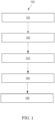
- FIG. 1 is a flowchart of a method for determining a target location of a single-slot collimating plate according to an embodiment of the present invention.
- a single-slot collimator including the single-slot collimating plate is disposed on an X-ray source side.
- the method shown in FIG. 1 is preferably performed by a control host of a CT system.
- the method includes the following steps.
- Step 101 Acquire a first measurement signal collected based on the first time of air scanning when a single-slot collimating plate moves from a start location to a first location by a predetermined distance along a first direction of a Z-axis.
- the Z-axis is a row arrangement direction of a detector array.
- the CT system When the single-slot collimating plate moves from the start location to the first location by the predetermined distance along the first direction of the Z-axis, the CT system performs the first time of air scanning.
- the detector array of the CT system detects a measurement signal (referred to as a first measurement signal) during the first time of air scanning.
- the first measurement signal is determined by X-ray intensity detected in the first time of air scanning in rows on the Z-axis.
- the X-ray intensity may be used to describe the first measurement signal, or a logarithm of the X-ray intensity may be used to describe the first measurement signal.
- the detector array sends the first measurement signal to the control host by using a transmission link such as a cable.
- Step 102 Acquire a second measurement signal collected based on the second time of air scanning when the single-slot collimating plate moves from the start location to a second location by the predetermined distance along an opposite direction of the first direction.
- the single-slot collimating plate returns from the first location to the start location. Further, when the single-slot collimating plate moves from the start location to the second location by the predetermined distance along the opposite direction of the first direction of the Z-axis, the CT system performs the second time of air scanning.
- the detector array detects a measurement signal (referred to as a second measurement signal) during the second time of air scanning.
- the second measurement signal is determined by X-ray intensity detected in the second time of air scanning in rows on the Z-axis.
- the X-ray intensity may be used to describe the second measurement signal, or a logarithm of the X-ray intensity may be used to describe the second measurement signal.
- the detector array sends the second measurement signal to the control host by using a transmission link such as a cable.
- FIG. 2 is a schematic cross-sectional diagram of air scanning of CT in a Z-axis direction according to an embodiment of the present invention.
- the single-slot collimating plate moves from the start location (initial) to a current location (initial - shift) by the predetermined distance (shift) along the reverse direction of the Z-axis shown in FIG. 2 (that is, the opposite direction of the arrow marked with Z in FIG. 2 ).
- the CT system performs the first time of air scanning. Specifically, an X ray emitted from a focal point 40 undergoes a beam limiting action of a single-slot collimating plate 10 moving to the current location (initial - shift) to form a transmission range defined by an X ray 12 and an X ray 13.
- the detector array 50 may detect a measurement signal identified by a complete solid line curve 70.
- the solid line curve 70 may not actually be fully detected.
- the detector array 50 that includes the first row R1, the second row R2, ..., and the nth row Rn detects, in the transmission range, a measurement signal identified by a solid line curve BE.
- a point B is an intersection point between a line connecting a tail end of the first row R1 in the reverse direction of the Z-axis and the focal point 40 and the solid line curve 70
- a point E is an intersection point between the X ray 13 and the detector array 50.
- the solid line curve BE is a part of the solid line curve 70.
- the solid line curve BE is a measurement signal (the first measurement signal) detected by the detector array 50 for the first time of air scanning, and is determined by intensity of X-rays detected in each row in the Z-axis direction in the first time of air scanning.
- the single-slot collimating plate returns from the current location (initial-shift) to the start location (initial) and moves from the start location (initial) to the current location (initial + shift) by the same predetermined distance (shift) in the forward direction of the Z-axis as shown in FIG. 2 (i.e., the arrow direction identified by Z in FIG. 2 ).
- the CT system performs the second time of air scanning. Specifically, an X ray emitted from a focal point 40 undergoes a beam limiting action of a single-slot collimating plate 11 moving to the current location (initial + shift) to form a transmission range defined by an X ray 14 and an X ray 15.
- the detector array 50 may detect a measurement signal identified by a complete dotted line curve 80.
- the dotted line curve 80 may not actually be fully detected.
- the detector array 50 that includes the first row R1, the second row R2, ..., and the nth row Rn detects, in the transmission range, a measurement signal identified by a dotted line curve DC.
- a point C is an intersection point between a line connecting a tail end of the nth row Rn in the forward direction of the Z-axis and the focal point 40 and the dotted line curve 80
- a point D is an intersection point between the X ray 14 and the detector array 50.
- the dotted line curve DC is a part of the dotted line curve 80.
- the dotted line curve DC is a measurement signal (the second measurement signal) detected by the detector array 50 for the second time of air scanning, and is determined by intensity of X-rays detected in each row in the Z-axis direction in the second time of air scanning.
- Step 103 Determine a combined measurement signal and a combined air calibration signal based on the first measurement signal and the second measurement signal.
- control host determines the combined measurement signal and the combined air calibration signal based on the first measurement signal and the second measurement signal.
- step 103 of determining a combined measurement signal and a combined air calibration signal based on the first measurement signal and the second measurement signal includes: determining a demarcation point between the first measurement signal and the second measurement signal; combining a first signal segment that is in the second measurement signal and that extends from the demarcation point along the first direction of the Z-axis with a second signal segment that is in the first measurement signal and that extends from the demarcation point along the opposite direction into the combined measurement signal; and combining a third signal segment that is in the first measurement signal and that extends from the demarcation point along the first direction of the Z-axis with a fourth signal segment that is in the second measurement signal and that extends from the demarcation point along the opposite direction into the combined air calibration signal.
- the demarcation point may be an intersection point between the first measurement signal and the second measurement signal, or may be a peripheral point of an intersection point between the first measurement signal and the second measurement signal.
- the point A is an intersection point between the first measurement signal and the second measurement signal.
- the point A is used as a demarcation point between the first measurement signal and the second measurement signal.
- a solid line AE included in the solid line curve BE is a second signal segment 17, and a dotted line DA included in the dotted line curve DC is a first signal segment 16.
- the first signal segment 16 and the second signal segment 17 are combined into a combined measurement signal.
- FIG. 3 is a schematic diagram of combining to obtain a combined measurement signal according to an embodiment of the present invention.
- the first signal segment 16 and the second signal segment 17 form a combined curve by using the point A, that is, a combined measurement signal.
- a solid line BA included in the solid line curve BE is a third signal segment 19, and a dotted line AC included in the dotted line curve DC is a fourth signal segment 18.
- the third signal segment 19 and the fourth signal segment 18 are combined into a combined air calibration signal.
- FIG. 4 is a schematic diagram of combining to obtain a combined air calibration signal according to an embodiment of the present invention.
- the third signal segment 19 and the fourth signal segment 18 form a combined curve by using the point A, that is, a combined air calibration signal.
- Step 104 Calibrate the combined measurement signal by using the combined air calibration signal.
- control host calibrates the combined air calibration signal by using the combined measurement signal, to obtain the calibrated combined measurement signal.
- the combined air calibration signal may be subtracted from the combined measurement signal to obtain the calibrated combined air calibration signal.
- the combined measurement signal may be divided by the combined air calibration signal to obtain the calibrated combined air calibration signal.
- FIG. 5 is a schematic diagram of a calibrated combined measurement signal according to an embodiment of the present invention.
- a calibrated combined measurement signal 90 is displayed in a coordinate system in which a serial number of a row is a horizontal axis and signal intensity is a vertical axis.
- Step 105 Determine a target location of the single-slot collimating plate based on the calibrated combined measurement signal.
- control host may first determine a center of gravity of the calibrated combined measurement signal, and then determine the target location of the single-slot collimating plate based on the center of gravity.
- COG center of gravity
- Each detector in the detector array has a plurality of channels in a channel direction, where the channel direction is an arrangement direction of the channels in the detector array.
- the detector array is usually an arcuate detector array, so the channel direction is usually arcuate.
- the Z-axis direction is the arrangement direction of rows in the detector array
- a channel direction ⁇ is located in an XY plane perpendicular to the Z-axis
- the channel direction ⁇ has an arcuate shape corresponding to an arcuate detector array.
- the left channel group, the right channel group, and the middle channel group between the left channel group and the right channel group can be determined in advance along the channel direction.
- the left channel group, the right channel group, and the middle channel group may be determined based on the number sequence of the channels arranged in the channel direction. For example, assuming that the detector array has 768 channels in the channel direction, channel 1 - channel 50 may be determined as the left channel group, channel 411 - channel 460 are determined as the middle channel group, and channel 719 - channel 768 are determined as the right channel group.
- a center of gravity of an average signal of each calibrated combined measurement signal detected by the middle channel group is determined, and a Z location offset of the single-slot collimating plate is determined based on the center of gravity.
- a first average signal of a calibrated combined measurement signal of each channel in the middle channel group is determined; a center of gravity of the first average signal is determined; and a Z location offset of the single-slot collimating plate is determined based on the center of gravity of the first average signal.
- the center of gravity of the first average signal is in a coordinate system in which a serial number of a row is a horizontal axis and signal intensity of an X ray is a vertical axis.
- the middle channel group includes channel 411 - channel 460.
- each channel in channel 411 - channel 460 may separately acquire a calibrated combined measurement signal 90 shown in FIG. 5 (in the coordinate system in which the row number is the horizontal axis and the signal intensity is the vertical axis). That is, the middle channel group may acquire a total of 50 calibrated combined measurement signals 90 as shown in FIG. 5 (respectively obtained by using channel 411 - channel 460).
- the average value of the 50 calibrated combined measurement signals 90 shown in FIG. 5 is the first average signal of the calibrated combined measurement signals of the channels in the middle channel group.
- the Z-location offset of the single-slot collimating plate can be determined.
- the Z location offset of the single-slot collimating plate can be conveniently determined by using the center of gravity of the first average signal formed by the middle channel group.
- a center of gravity of an average signal of the combined measurement signal detected by the left channel group is determined
- a center of gravity of an average signal of the combined measurement signal detected by the right channel group is determined
- parallelism of the single-slot collimating plate is determined based on the two centers of gravity.
- the parallelism of the single-slot collimating plate reflects parallelism between emergent light of a collimator and a mechanical axis of the collimator.
- a second average signal of a calibrated combined measurement signal of each channel in the left channel group is determined; a center of gravity of the second average signal is determined; a third average signal of a calibrated combined measurement signal of each channel in the right channel group is determined; a center of gravity of the third average signal is determined; and parallelism of the single-slot collimating plate is determined based on the center of gravity of the second average signal and the center of gravity of the third average signal.
- Both the center of gravity of the second average signal and the center of gravity of the third average signal are in the coordinate system in which the serial number of the row is the horizontal axis and the signal intensity of the X ray is the vertical axis.
- each channel in channel 1 - channel 50 and channel 411 - channel 460 may separately acquire a calibrated combined measurement signal 90 shown in FIG. 5 (in the coordinate system in which the row number is the horizontal axis and the signal intensity is the vertical axis).
- the left channel group may acquire a total of 50 calibrated combined measurement signals 90 as shown in FIG. 5 (respectively obtained by using channel 1 - channel 50).
- the right channel group may acquire a total of 50 calibrated combined measurement signals 90 as shown in FIG. 5 (respectively obtained by using channel 719 - channel 768).
- the average value of the 50 combined measurement signals 90 acquired by the left channel group is a second average signal of the calibrated combined measurement signals of each channel in the left channel group.
- the average value of the 50 combined measurement signals 90 acquired by the right channel group is a third average signal of the calibrated combined measurement signals of each channel in the right channel group.
- the parallelism of the single-slot collimating plate can be conveniently determined by using the center of gravity of the second average signal formed by the left channel group and the center of gravity of the third average signal formed by the right channel group.
- curvature of the single-slot collimating plate is determined based on the center of gravity of the second average signal, the center of gravity of the third average signal, and the center of gravity of the first average signal.
- alarm information indicating to replace the single-slot collimating plate is sent.
- the center of gravity of the first average signal, the center of gravity of the second average signal, and the center of gravity of the third average signal are all located in the coordinate system in which the serial number of the row is the horizontal axis and the signal intensity of the X ray is the vertical axis.
- each channel in the middle channel group, the left channel group, and the right channel group may separately acquire a calibrated combined measurement signal 90 shown in FIG. 5 (in the coordinate system in which the row number is the horizontal axis and the signal intensity is the vertical axis).
- the middle channel group may acquire a total of 50 calibrated combined measurement signals 90 as shown in FIG. 5 (respectively obtained by using channel 411 - channel 460).
- the average value of the 50 calibrated combined measurement signals 90 acquired by the middle channel group as shown in FIG. 5 is the first average signal of the calibrated combined measurement signals of the channels in the middle channel group.
- the left channel group may acquire a total of 50 calibrated combined measurement signals 90 as shown in FIG. 5 (respectively obtained by using channel 1 - channel 50).
- the average value of the 50 combined measurement signals 90 acquired by the left channel group is a second average signal of the calibrated combined measurement signals of each channel in the left channel group.
- the right channel group may acquire a total of 50 calibrated combined measurement signals 90 as shown in FIG. 5 (respectively obtained by using channel 719 - channel 768).
- the average value of the 50 combined measurement signals 90 acquired by the right channel group is a third average signal of the calibrated combined measurement signals of each channel in the right channel group.
- the curvature of the single-slot collimating plate may be determined based on the center of gravity of the first average signal, the center of gravity of the second average signal, the center of gravity of the third average signal, and the fixed parameter of the CT system (for example, a distance between the focal point and the single-slot collimating plate, a distance between the focal point and the ISO, an actual layer width of the detector array, the total quantity of channels, the maximum channel number in the left channel group, and the maximum channel number in a right channel group).
- the fixed parameter of the CT system for example, a distance between the focal point and the single-slot collimating plate, a distance between the focal point and the ISO, an actual layer width of the detector array, the total quantity of channels, the maximum channel number in the left channel group, and the maximum channel number in a right channel group.
- the curvature of the single-slot collimating plate can be conveniently determined based on the center of gravity of the second average signal, the center of gravity of the third average signal, and the center of gravity of the first average signal, and an alarm is given when the curvature exceeds the threshold.
- the left channel group L, the right channel group R, and the middle channel group M located between the left channel group L and the right channel group R are determined.
- the single-slot collimating plate moves by a predetermined distance shift in a direction (for example, the reverse direction of the Z-axis) of the Z-axis from the start location z-initial on the Z-axis, arrives at the location initial-shift, and performs the first time of air scanning.
- Measurement data acquired by the detector array is S - (m,q,n), where m is a channel number, q is a row number, and n is a reading.
- the single-slot collimating plate returns from the upright location to the start location Z-initial, moves by the same predetermined distance shift in another direction of the Z-axis (for example, the forward direction of Z-axis), arrives at the location initial + shift, and performs the second time of air scanning.
- Measurement data acquired by the detector array is S + (m,q,n).
- the measurement data S - (m,q,n) acquired during the first time of air scanning may be pre-checked, so as to ensure that the start location z-initial is acceptable.
- the combined measurement signal data combine ( m, q, n ) is calibrated by using the combined air calibration signal aircal combine ( m, q, n ), and is averaged on the reading n to obtain the calibrated combined measurement signal S comb ′ m q .
- S + ( m, q, n ) and S - ( m, q, n ) are respectively represented by logarithms of X-ray intensity detected in respective air scanning
- S comb ′ m q is the average value of data combine ( m, q, n ) - aircal combine ( m , q, n ) on the reading n.
- ⁇ Z equal Parallel should meet the following conditions: ⁇ Z equal Parallel ⁇ ⁇ Z Parallel ⁇ Z Parallel is the parallelism threshold value of the single-slot collimating plate.
- the calculated curvature should meet the following conditions: Z optimal L + Z optimal R ⁇ 2 ⁇ Z optimal M 2 ⁇ ⁇ Z Curv ⁇ Z Curv is a threshold value of the curvature.
- tuning up of the slot can be completed by using signal combination through only two times of air measurement, which is more efficient, simpler, and convenient.
- costs such as a mechanical motor or a control component can be further reduced in the embodiment of the present invention.
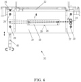
- FIG. 6 is a first schematic diagram of tuning up a target location of a single-slot collimating plate in a collimator assembly nor forming part of the present invention.
- the location of the collimating plate can be conveniently tuned up without using a mechanical motor or a control component.
- a collimator assembly 20 includes:
- the rotating carrier 22 may be implemented as a flange-shaped structural component, and provides fixed support for a rotating component such as a ball tube, a collimator assembly, and a detector.
- the single-slot collimating plate 23 is preferably made of an X-ray shielding material of high-density metal such as a tungsten alloy.
- the rotation amount of the frame 21 around the rotational fulcrum 24 may be tuned up by using a micrometer caliper 40 coupled to a first end of the frame 21, so that the parallelism of the single-slot collimating plate 23 meets the target value.
- a gasket of an appropriate specification is filled in the recess 26, so that a Z location of the single-slot collimating plate 23 meets the Z location offset.
- a locating pin 28 is disposed at a location on the frame 21 that is opposite to the recess opening to fix the gasket in the recess 26.
- two parallel handles 27 are disposed at two ends of the single-slot collimating plate 23 along the Z-axis direction. A user may conveniently move the frame 21 by using the two handles 27.
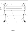
- FIG. 7 is a second schematic diagram of tuning up a target location of a single-slot collimating plate in a collimator assembly not forming part of the present invention.
- the location of the slot may be tuned up without using a mechanical motor or a control component.
- a collimator assembly 30 includes:
- the frame 31 may be disposed on the rotating carrier.
- the rotating carrier may be implemented as a flange-shaped structural component, and provides fixed support for a rotating component such as a ball tube, a collimator assembly, and a detector.
- Example 1 When the control host determines the Z location offset and the target value of the parallelism of the single-slot collimating plate 37 based on the method for determining a target location of a single-slot collimating plate shown in FIG. 1 , and the user finds that current parallelism of the single-slot collimating plate 37 is equal to the target value, the user synchronously tunes up a first micrometer caliper 41 coupled to a first end of the single-slot collimating plate 37 and a second micrometer caliper 42 coupled to a second end of the single-slot collimating plate 37, so that the single-slot collimating plate 37 keeps moving in the Z direction with the parallelism, and the Z location to which the single-slot collimating plate 37 moves meets the Z location offset.
- Example 2 When the control host determines the Z location offset and the target value of the parallelism of the single-slot collimating plate 37 based on the method for determining a target location of a single-slot collimating plate shown in FIG. 1 , and the user finds that current parallelism of the single-slot collimating plate 37 is not equal to the target value, the user may simultaneously tune up a first micrometer caliper 41 coupled to a first end of the single-slot collimating plate 37 and a second micrometer caliper 42 coupled to a second end of the single-slot collimating plate 37, so that the single-slot collimating plate 37 reaches the parallelism and moves in the Z direction, and the Z location to which the single-slot collimating plate 37 moves meets the Z location offset.
- a first micrometer caliper 41 coupled to a first end of the single-slot collimating plate 37
- a second micrometer caliper 42 coupled to a second end of the single-slot collimating plate 37
- Example 3 When the control host determines the Z location offset and the target value of the parallelism of the single-slot collimating plate 37 based on the method for determining a target location of a single-slot collimating plate shown in FIG. 1 , and the user finds that current parallelism of the single-slot collimating plate 37 is not equal to the target value, the user may separately tune up a first micrometer caliper 41 coupled to a first end of the single-slot collimating plate 37 or separately tune up a second micrometer caliper 42 coupled to a second end of the single-slot collimating plate 37, so that the single-slot collimating plate 37 reaches the parallelism and moves in the Z direction, and the Z location to which the single-slot collimating plate 37 moves meets the Z location offset.
- an embodiment of the present invention further provides an apparatus for determining a target location of a single-slot collimating plate.
- FIG. 8 is a structural diagram of an apparatus for determining a target location of a single-slot collimating plate according to an embodiment of the present invention.
- an apparatus 800 includes:
- the first determining module 803 is configured to: determine a demarcation point between the first measurement signal and the second measurement signal; combine a first signal segment that is in the second measurement signal and that extends from the demarcation point along the first direction of the Z-axis with a second signal segment that is in the first measurement signal and that extends from the demarcation point along the opposite direction into the combined measurement signal; and combine a third signal segment that is in the first measurement signal and that extends from the demarcation point along the first direction of the Z-axis with a fourth signal segment that is in the second measurement signal and that extends from the demarcation point along the opposite direction into the combined air calibration signal.
- the second determining module 805 is configured to: determine a center of gravity of the calibrated combined measurement signal, and determine the target location of the single-slot collimating plate based on the center of gravity.
- the second determining module 805 is configured to: determine a left channel group, a right channel group, and a middle channel group between the left channel group and the right channel group based on a channel number sequence; determine a first average signal of a calibrated combined measurement signal of each channel in the middle channel group; determine a center of gravity of the first average signal; and determine a Z-location offset of the single-slot collimating plate based on the center of gravity of the first average signal.
- the second determining module 805 is further configured to: determine a second average signal of a calibrated combined measurement signal of each channel in the left channel group; determine a center of gravity of the second average signal; determine a third average signal of a calibrated combined measurement signal of each channel in the right channel group; determine a center of gravity of the third average signal; and determine parallelism of the single-slot collimating plate based on the center of gravity of the second average signal and the center of gravity of the third average signal.
- the second determining module 805 is further configured to determine curvature of the single-slot collimating plate based on the center of gravity of the second average signal, the center of gravity of the third average signal, and the center of gravity of the first average signal.
- the apparatus 800 further includes an alarm module 806, configured to: when the curvature is greater than a predetermined curvature threshold, send alarm information indicating to replace the single-slot collimating plate.
- an embodiment of the present invention further provides a control host of a CT system.
- FIG. 9 is a structural diagram of a control host of a CT system according to an embodiment of the present invention.
- a control host 900 includes a memory 901 and a processor 902, where the memory 901 stores an application program capable of being executed by the processor 902, so that the processor 902 executes the method for determining a target location of a single-slot collimating plate.
- the memory 901 may be specifically implemented as a plurality of storage media such as an electrically erasable programmable read-only memory (EEPROM), a flash memory, and a programmable program read-only memory (PROM).
- the processor 902 may be implemented as one or more central processing units or one or more field programmable gate arrays, where the field programmable gate array is integrated into one or more central processing units.
- the central processing unit or the central processing unit core may be implemented as a CPU, an MCU, a DSP, or the like.
- Hardware modules in the foregoing embodiments may be implemented in a mechanical manner or an electronic manner.
- a hardware module may include a specially designed permanent circuit or logic device (such as a dedicated processor like an FPGA or an ASIC) for performing a specific operation.
- the hardware module may also include a programmable logic device or circuit (such as a general purpose processor or another programmable processor) that is temporarily configured by software to perform a specific operation.
- Whether the hardware module is specifically implemented in the mechanical manner, by using a dedicated permanent circuit, or by using a temporarily configured circuit (configured using software) may be determined according to costs and time considerations.
- the present invention further provides a machine readable storage medium for storing instructions for causing a machine to execute the method described herein.
- a system or an apparatus equipped with a storage medium may be provided.
- Software program code for implementing a function in any one of the foregoing embodiments is stored in the storage medium, and a computer (or a CPU or an MPU) of the system or apparatus reads and executes program code stored in the storage medium.
- an operating system operated on a computer or the like may be enabled to complete some or all actual operations by using a program code-based instruction.
- the program code read from the storage medium may be written into a memory disposed in an extension board inserted into the computer or into a memory disposed in an extension unit connected to the computer.
- a program code-based instruction enables a CPU installed on the extension board or the extension unit to perform some and all actual operations, so as to implement a function of any one of the foregoing embodiments.
- the storage medium embodiment for providing program code includes a floppy disk, a hard disk, a magneto-optical disk, an optical disc (such as a CD-ROM, a CD-R, a CD-RW, a DVD-ROM, a DVD-RAM, a DVD-RW, and a DVD+RW), a magnetic tape, a non-volatile memory card, and a ROM.
- program code may be downloaded from a server computer via a communication network.
Landscapes
- Health & Medical Sciences (AREA)
- Life Sciences & Earth Sciences (AREA)
- Engineering & Computer Science (AREA)
- Medical Informatics (AREA)
- Optics & Photonics (AREA)
- Biomedical Technology (AREA)
- Biophysics (AREA)
- High Energy & Nuclear Physics (AREA)
- Veterinary Medicine (AREA)
- Nuclear Medicine, Radiotherapy & Molecular Imaging (AREA)
- Public Health (AREA)
- Pathology (AREA)
- Radiology & Medical Imaging (AREA)
- Physics & Mathematics (AREA)
- Heart & Thoracic Surgery (AREA)
- Molecular Biology (AREA)
- Surgery (AREA)
- Animal Behavior & Ethology (AREA)
- General Health & Medical Sciences (AREA)
- Pulmonology (AREA)
- Theoretical Computer Science (AREA)
- Apparatus For Radiation Diagnosis (AREA)
- Measurement Of Radiation (AREA)
Claims (12)
- Verfahren (100) zum Bestimmen einer Zielposition einer Einzelschlitzkollimationsplatte, Folgendes umfassend:Erfassen eines ersten Messsignals, das auf Grundlage des ersten Luftabtastungszeitraums aufgenommen wird, wenn sich eine Einzelschlitzkollimationsplatte von einer Startposition um einen vorbestimmten Abstand entlang einer ersten Richtung einer Z-Achse (101) zu einer ersten Position bewegt, wobei der erste Luftabtastungszeitraum durchgeführt wird, wenn die Einzelschlitzkollimationsplatte die erste Position erreicht, wobei das erste Messsignal durch eine Röntgenstrahlungsintensität bestimmt wird, die im ersten Luftabtastungszeitraum in Zeilen einer Detektormatrix auf der Z-Achse detektiert wird;Erfassen eines zweiten Messsignals, das auf Grundlage des zweiten Luftabtastungszeitraums aufgenommen wird, wenn sich die Einzelschlitzkollimationsplatte von der Startposition um den vorbestimmten Abstand entlang einer entgegengesetzten Richtung der ersten Richtung (102) zu einer zweiten Position bewegt, wobei der zweite Luftabtastungszeitraum durchgeführt wird, wenn die Einzelschlitzkollimationsplatte die zweite Position erreicht, wobei das zweite Messsignal durch eine Röntgenstrahlungsintensität bestimmt wird, die im ersten Luftabtastungszeitraum in Zeilen einer Detektormatrix auf der Z-Achse detektiert wird;Bestimmen eines kombinierten Messsignals und eines kombinierten Luftkalibrierungssignals auf Grundlage des ersten Messsignals und des zweiten Messsignals (103), wobei das Bestimmen Folgendes umfasst:Bestimmen eines Demarkationspunkts zwischen dem ersten Messsignal und dem zweiten Messsignal;Kombinieren eines ersten Signalsegments, das in dem zweiten Messsignal ist und sich von dem Demarkationspunkt entlang der ersten Richtung der Z-Achse erstreckt, mit einem zweiten Signalsegment, das in dem ersten Messsignal ist und sich von dem Demarkationspunkt entlang der entgegengesetzten Richtung in das kombinierte Messsignal erstreckt, um das kombinierte Messsignal zu erlangen;Kombinieren eines dritten Signalsegments, das in dem ersten Messsignal ist und sich von dem Demarkationspunkt entlang der ersten Richtung der Z-Achse erstreckt, mit einem vierten Signalsegment, das in dem zweiten Messsignal ist und sich von dem Demarkationspunkt entlang der entgegengesetzten Richtung in das kombinierte Luftkalibrierungssignal erstreckt, um das kombinierte Luftkalibrierungssignal zu erlangen;Kalibrieren des kombinierten Messsignals unter Verwendung des kombinierten Luftkalibrierungssignals (104), wobei das Kalibrieren Folgendes umfasst:Subtrahieren des kombinierten Luftkalibrierungssignals von dem kombinierten Messsignal, wenn sowohl das erste Messsignal als auch das zweite Messsignal unter Verwendung von Logarithmen der detektierten Röntgenstrahlungsintensität beschrieben werden, oderDividieren des kombinierten Messsignals durch das kombinierte Luftkalibrierungssignal, wenn sowohl das erste Messsignal als auch das zweite Messsignal unter Verwendung der detektierten Röntgenstrahlungsintensität und nicht unter Verwendung von Logarithmen der detektierten Röntgenstrahlungsintensität beschrieben werden; undBestimmen einer Zielposition der Einzelschlitzkollimationsplatte auf Grundlage des kalibrierten kombinierten Messsignals (105).
- Verfahren (100) nach Anspruch 1, wobei das Bestimmen einer Zielposition der Einzelschlitzkollimationsplatte auf Grundlage des kalibrierten kombinierten Messsignals (105) Folgendes umfasst:Bestimmen eines Schwerpunkts des kalibrierten kombinierten Messsignals; undBestimmen der Zielposition der Einzelschlitzkollimationsplatte auf Grundlage des Schwerpunkts.
- Verfahren (100) nach Anspruch 2, wobei
das Bestimmen eines Schwerpunkts des kalibrierten kombinierten Messsignals Folgendes umfasst:Bestimmen einer linken Kanalgruppe, einer rechten Kanalgruppe und einer mittleren Kanalgruppe zwischen der linken Kanalgruppe und der rechten Kanalgruppe auf Grundlage einer Kanalnummersequenz;Bestimmen eines ersten durchschnittlichen Signals eines kalibrierten kombinierten Messsignals jedes Kanals in der mittleren Kanalgruppe; undBestimmen eines Schwerpunkts des ersten durchschnittlichen Signals; unddas Bestimmen der Zielposition der Einzelschlitzkollimationsplatte auf Grundlage des Schwerpunkts Folgendes umfasst: Bestimmen eines Z-Positionsversatzes der Einzelschlitzkollimationsplatte auf Grundlage des Schwerpunkts des ersten durchschnittlichen Signals. - Verfahren (100) nach Anspruch 3, wobei
das Bestimmen eines Schwerpunkts des kalibrierten kombinierten Messsignals weiterhin Folgendes umfasst:Bestimmen eines zweiten durchschnittlichen Signals eines kalibrierten kombinierten Messsignals jedes Kanals in der linken Kanalgruppe;Bestimmen eines Schwerpunkts des zweiten durchschnittlichen Signals;Bestimmen eines dritten durchschnittlichen Signals eines kalibrierten kombinierten Messsignals jedes Kanals in der rechten Kanalgruppe; undBestimmen eines Schwerpunkts des dritten durchschnittlichen Signals; unddas Bestimmen der Zielposition der Einzelschlitzkollimationsplatte auf Grundlage des Schwerpunkts weiterhin Folgendes umfasst: Bestimmen einer Parallelität der Einzelschlitzkollimationsplatte auf Grundlage des Schwerpunkts des zweiten durchschnittlichen Signals und des Schwerpunkts des dritten durchschnittlichen Signals. - Verfahren (100) nach Anspruch 4, wobei das Verfahren weiterhin Folgendes umfasst:Bestimmen einer Krümmung der Einzelschlitzkollimationsplatte auf Grundlage des Schwerpunkts des zweiten durchschnittlichen Signals, des Schwerpunkts des dritten durchschnittlichen Signals und des Schwerpunkts des ersten durchschnittlichen Signals; undSenden von Alarminformationen, die angeben, die Einzelschlitzkollimationsplatte zu ersetzen, wenn die Krümmung größer ist als ein vorbestimmter Krümmungsschwellenwert.
- Vorrichtung (800) zum Bestimmen einer Zielposition einer Einzelschlitzkollimationsplatte, Folgendes umfassend:ein erstes Erfassungsmodul (801), das eingerichtet ist, um ein erstes Messsignal zu erfassen, das auf Grundlage des ersten Luftabtastungszeitraums aufgenommen wird, wenn sich eine Einzelschlitzkollimationsplatte von einer Startposition um einen vorbestimmten Abstand entlang einer ersten Richtung einer Z-Achse zu einer ersten Position bewegt, wobei der erste Luftabtastungszeitraum durchgeführt wird, wenn die Einzelschlitzkollimationsplatte die erste Position erreicht, wobei das erste Messsignal durch eine Röntgenstrahlungsintensität bestimmt wird, die im ersten Luftabtastungszeitraum in Zeilen einer Detektormatrix auf der Z-Achse detektiert wird;ein zweites Erfassungsmodul (802), das eingerichtet ist, um ein erstes Messsignal zu erfassen, das auf Grundlage des ersten Luftabtastungszeitraums aufgenommen wird, wenn sich die Einzelschlitzkollimationsplatte von der Startposition um den vorbestimmten Abstand entlang einer entgegengesetzten Richtung der ersten Richtung zu einer zweiten Position bewegt, wobei der zweite Luftabtastungszeitraum durchgeführt wird, wenn die Einzelschlitzkollimationsplatte die zweite Position erreicht, wobei das zweite Messsignal durch eine Röntgenstrahlungsintensität bestimmt wird, die im ersten Luftabtastungszeitraum in Zeilen einer Detektormatrix auf der Z-Achse detektiert wird;ein erstes Bestimmungsmodul (803), das eingerichtet ist, um ein kombiniertes Messsignal und ein kombiniertes Luftkalibrierungssignal auf Grundlage des ersten Messsignals und des zweiten Messsignals zu bestimmen, wobei das erste Bestimmungsmodul eingerichtet ist, um:einen Demarkationspunkt zwischen dem ersten Messsignal und dem zweiten Messsignal zu bestimmen;ein erstes Signalsegment, das in dem zweiten Messsignal ist und sich von dem Demarkationspunkt entlang der ersten Richtung der Z-Achse erstreckt, mit einem zweiten Signalsegment zu kombinieren, das in dem ersten Messsignal ist und sich von dem Demarkationspunkt entlang der entgegengesetzten Richtung in das kombinierte Messsignal erstreckt, um das kombinierte Messsignal zu erlangen;ein drittes Signalsegment, das in dem ersten Messsignal ist und sich von dem Demarkationspunkt entlang der ersten Richtung der Z-Achse erstreckt, mit einem vierten Signalsegment zu kombinieren, das in dem zweiten Messsignal ist und sich von dem Demarkationspunkt entlang der entgegengesetzten Richtung in das kombinierte Luftkalibrierungssignal erstreckt, um das kombinierte Luftkalibrierungssignal zu erlangen;ein Kalibrierungsmodul (804), das eingerichtet ist, um das kombinierte Messsignal unter Verwendung des kombinierten Luftkalibrierungssignals zu kalibrieren, wobei das Kalibrierungsmodul eingerichtet ist, um:das kombinierte Luftkalibrierungssignal von dem kombinierten Messsignal zu subtrahieren, wenn sowohl das erste Messsignal als auch das zweite Messsignal unter Verwendung von Logarithmen der detektierten Röntgenstrahlungsintensität beschrieben werden, oderdas kombinierte Messsignal durch das kombinierte Luftkalibrierungssignal zu dividieren, wenn sowohl das erste Messsignal als auch das zweite Messsignal unter Verwendung der detektierten Röntgenstrahlungsintensität und nicht unter Verwendung von Logarithmen der detektierten Röntgenstrahlungsintensität beschrieben werden; undein zweites Bestimmungsmodul (805), das eingerichtet ist, um eine Zielposition der Einzelschlitzkollimationsplatte auf Grundlage des kalibrierten kombinierten Messsignals zu bestimmen.
- Vorrichtung (800) nach Anspruch 6, wobei
das zweite Bestimmungsmodul (805) eingerichtet ist, um: einen Schwerpunkt des kalibrierten kombinierten Messsignals zu bestimmen und die Zielposition der Einzelschlitzkollimationsplatte auf Grundlage des Schwerpunkts zu bestimmen. - Vorrichtung (800) nach Anspruch 7, wobei
das zweite Bestimmungsmodul (805) eingerichtet ist, um: eine linke Kanalgruppe, eine rechte Kanalgruppe und eine mittlere Kanalgruppe zwischen der linken Kanalgruppe und der rechten Kanalgruppe auf Grundlage einer Kanalnummersequenz zu bestimmen; ein erstes durchschnittliches Signal eines kalibrierten kombinierten Messsignals jedes Kanals in der mittleren Kanalgruppe zu bestimmen; einen Schwerpunkt des ersten durchschnittlichen Signals zu bestimmen; und einen Z-Positionsversatz der Einzelschlitzkollimationsplatte auf Grundlage des Schwerpunkts des ersten durchschnittlichen Signals zu bestimmen. - Vorrichtung (800) nach Anspruch 8, wobei
das zweite Bestimmungsmodul (805) weiterhin eingerichtet ist, um: ein zweites durchschnittliches Signal eines kalibrierten kombinierten Messsignals jedes Kanals in der linken Kanalgruppe zu bestimmen; einen Schwerpunkt des zweiten durchschnittlichen Signals zu bestimmen; ein drittes durchschnittliches Signal eines kalibrierten kombinierten Messsignals jedes Kanals in der rechten Kanalgruppe zu bestimmen; einen Schwerpunkt des dritten durchschnittlichen Signals zu bestimmen; und eine Parallelität der Einzelschlitzkollimationsplatte auf Grundlage des Schwerpunkts des zweiten durchschnittlichen Signals und des Schwerpunkts des dritten durchschnittlichen Signals zu bestimmen. - Vorrichtung (800) nach Anspruch 9, wobeidas zweite Bestimmungsmodul (805) weiterhin eingerichtet ist, um eine Krümmung der Einzelschlitzkollimationsplatte auf Grundlage des Schwerpunkts des zweiten durchschnittlichen Signals, des Schwerpunkts des dritten durchschnittlichen Signals und des Schwerpunkts des ersten durchschnittlichen Signals zu bestimmen; unddie Vorrichtung (800) weiterhin Folgendes umfasst:
ein Alarmmodul (806), das eingerichtet ist, um: Alarminformationen zu senden, die angeben, die Einzelschlitzkollimationsplatte zu ersetzen, wenn die Krümmung größer ist als ein vorbestimmter Krümmungsschwellenwert. - Steuerungshost (900) eines CT-Systems, einen Speicher (901) und einen Prozessor (902) umfassend, wobei der Speicher (901) ein Anwendungsprogramm speichert, das durch den Prozessor (902) ausgeführt werden kann, so dass der Prozessor (902) das Verfahren (100) zum Bestimmen einer Zielposition einer Einzelschlitzkollimationsplatte nach einem der Ansprüche 1 bis 5 durchführt.
- Computerlesbares Speichermedium, wobei das computerlesbare Speichermedium ein Computerprogramm speichert und das Computerprogramm durch einen Prozessor eines Steuerungshosts eines CT-Systems ausgeführt wird, um das Verfahren (100) zum Bestimmen einer Zielposition einer Einzelschlitzkollimationsplatte nach einem der Ansprüche 1 bis 5 zu implementieren.
Applications Claiming Priority (1)
| Application Number | Priority Date | Filing Date | Title |
|---|---|---|---|
| PCT/CN2020/095439 WO2021139088A1 (zh) | 2020-06-10 | 2020-06-10 | 确定单槽准直板的目标位置的方法、装置和准直器组件 |
Publications (3)
| Publication Number | Publication Date |
|---|---|
| EP4147641A1 EP4147641A1 (de) | 2023-03-15 |
| EP4147641A4 EP4147641A4 (de) | 2024-05-15 |
| EP4147641B1 true EP4147641B1 (de) | 2024-12-04 |
Family
ID=76787692
Family Applications (1)
| Application Number | Title | Priority Date | Filing Date |
|---|---|---|---|
| EP20911981.7A Active EP4147641B1 (de) | 2020-06-10 | 2020-06-10 | Verfahren und vorrichtung zur bestimmung der zielposition einer einzelschlitzkollimationsplatte und kollimatoranordnung |
Country Status (4)
| Country | Link |
|---|---|
| US (1) | US12232896B2 (de) |
| EP (1) | EP4147641B1 (de) |
| CN (1) | CN115768353B (de) |
| WO (1) | WO2021139088A1 (de) |
Families Citing this family (1)
| Publication number | Priority date | Publication date | Assignee | Title |
|---|---|---|---|---|
| CN116313211A (zh) * | 2023-01-31 | 2023-06-23 | 散裂中子源科学中心 | 位姿调节装置及微小角谱仪直准器 |
Family Cites Families (17)
| Publication number | Priority date | Publication date | Assignee | Title |
|---|---|---|---|---|
| JPH0938074A (ja) | 1995-07-26 | 1997-02-10 | Ge Yokogawa Medical Syst Ltd | X線ct装置の焦点位置データ取得方法およびx線ct装置 |
| US7046768B1 (en) * | 2003-11-10 | 2006-05-16 | Inspx Llc | Shutter-shield for x-ray protection |
| DE102008050851B4 (de) | 2008-10-08 | 2010-11-11 | Incoatec Gmbh | Röntgenanalyseinstrument mit verfahrbarem Aperturfenster |
| CN101919700B (zh) * | 2009-06-10 | 2012-07-18 | 上海西门子医疗器械有限公司 | 一种准直器调节方法和装置 |
| DE102011080607A1 (de) * | 2011-08-08 | 2013-02-14 | Siemens Aktiengesellschaft | Röntgengerät und Verfahren zum Betrieb eines Röntgengerätes |
| US9135728B2 (en) * | 2012-04-04 | 2015-09-15 | General Electric Company | System and method for multi-energy computed tomography imaging |
| WO2014207193A1 (en) * | 2013-06-28 | 2014-12-31 | Koninklijke Philips N.V. | Correction in slit-scanning phase contrast imaging |
| JP6109665B2 (ja) * | 2013-07-18 | 2017-04-05 | 株式会社日立製作所 | 画像診断装置 |
| JP6322164B2 (ja) * | 2015-07-21 | 2018-05-09 | 株式会社モリタ製作所 | 医療用x線撮影装置 |
| US10314553B2 (en) * | 2016-01-21 | 2019-06-11 | FMI Medical Systems Co., Ltd. | Focal spot position control using pre-patient collimator with beam tracking |
| CN105748098A (zh) * | 2016-02-29 | 2016-07-13 | 上海联影医疗科技有限公司 | 限束器校正方法及装置、医学影像设备 |
| CN207489501U (zh) * | 2017-07-13 | 2018-06-12 | 上海西门子医疗器械有限公司 | 准直器 |
| DE102017220529B4 (de) * | 2017-11-17 | 2025-09-04 | Siemens Healthineers Ag | Verfahren zur Bedienung einer Blendeneinrichtung einer Röntgeneinrichtung und Röntgeneinrichtung |
| CN109893153B (zh) * | 2017-12-08 | 2023-10-20 | 上海西门子医疗器械有限公司 | 调整准直器位置的方法和装置 |
| WO2020029148A1 (zh) * | 2018-08-08 | 2020-02-13 | 西安大医集团有限公司 | 一种放疗设备准直器校正方法及装置 |
| CN109431534B (zh) * | 2018-11-30 | 2022-12-06 | 深圳安科高技术股份有限公司 | 一种射线准直器的自校准方法及其系统 |
| CN109770935B (zh) * | 2018-12-28 | 2022-04-15 | 上海联影医疗科技股份有限公司 | 准直器校正方法、装置、ct系统及存储介质 |
-
2020
- 2020-06-10 EP EP20911981.7A patent/EP4147641B1/de active Active
- 2020-06-10 CN CN202080101829.4A patent/CN115768353B/zh active Active
- 2020-06-10 US US18/001,132 patent/US12232896B2/en active Active
- 2020-06-10 WO PCT/CN2020/095439 patent/WO2021139088A1/zh not_active Ceased
Also Published As
| Publication number | Publication date |
|---|---|
| WO2021139088A1 (zh) | 2021-07-15 |
| EP4147641A4 (de) | 2024-05-15 |
| CN115768353A (zh) | 2023-03-07 |
| US20230210480A1 (en) | 2023-07-06 |
| US12232896B2 (en) | 2025-02-25 |
| EP4147641A1 (de) | 2023-03-15 |
| CN115768353B (zh) | 2026-02-10 |
Similar Documents
| Publication | Publication Date | Title |
|---|---|---|
| US8699659B2 (en) | Systems and methods for focal spot motion correction | |
| US9029786B2 (en) | Nuclear medicine imaging apparatus, and nuclear medicine imaging method | |
| US8983165B2 (en) | System and method for measuring X-ray beam profile using an area detector | |
| EP0526970A2 (de) | Bilderzeugungsgerät und Verfahren | |
| US8761483B2 (en) | Calibration system for focal spot shift in an X-ray CT device | |
| US8184766B2 (en) | X-ray computer tomograph and method for investigating an object by means of X-ray computer tomography | |
| US20120321041A1 (en) | Methods and apparatus for collimation of detectors | |
| EP0962786A1 (de) | Gammakamera | |
| US20160199019A1 (en) | Method and apparatus for focal spot position tracking | |
| US7056020B2 (en) | Alignment systems and methods for radiographic imaging systems | |
| US7286639B2 (en) | Focal spot sensing device and method in an imaging system | |
| CN110559001B (zh) | 一种ct扫描仪散焦辐射强度分布测量方法 | |
| US20030167142A1 (en) | Method and apparatus for reconstruction calibration of detector position and source motion based on a multi-pin phantom | |
| US12232896B2 (en) | Method and apparatus for determining target location of single-slot collimating plate and collimator assembly | |
| JP5469952B2 (ja) | X線ct装置 | |
| US7286631B2 (en) | Method and apparatus for tomosynthesis image quality control | |
| US7825370B2 (en) | Method and system for calibrating a computed tomography system | |
| US8315428B2 (en) | Automatic line identification and pairing for nuclear imaging collimator vector map characterization | |
| US20120177268A1 (en) | System and Method for Measuring Hole Orientation for SPECT Collimators | |
| CN112649451B (zh) | 用于大型对象的快速工业计算机断层扫描 | |
| JP7746450B2 (ja) | ワイヤファントムを用いたct検出器の較正のためのシステム及び方法 | |
| US7362844B2 (en) | Tomography appliance, and method for a tomography appliance | |
| US7111985B2 (en) | Method and system for measuring table sag | |
| US7399119B2 (en) | Method and system for measuring an alignment of a detector | |
| EP3035082B1 (de) | Verfahren zur messung der röntgenstrahlenergie eines beschleunigers in einem inspektionssystem |
Legal Events
| Date | Code | Title | Description |
|---|---|---|---|
| STAA | Information on the status of an ep patent application or granted ep patent |
Free format text: STATUS: THE INTERNATIONAL PUBLICATION HAS BEEN MADE |
|
| PUAI | Public reference made under article 153(3) epc to a published international application that has entered the european phase |
Free format text: ORIGINAL CODE: 0009012 |
|
| STAA | Information on the status of an ep patent application or granted ep patent |
Free format text: STATUS: REQUEST FOR EXAMINATION WAS MADE |
|
| 17P | Request for examination filed |
Effective date: 20221208 |
|
| AK | Designated contracting states |
Kind code of ref document: A1 Designated state(s): AL AT BE BG CH CY CZ DE DK EE ES FI FR GB GR HR HU IE IS IT LI LT LU LV MC MK MT NL NO PL PT RO RS SE SI SK SM TR |
|
| DAV | Request for validation of the european patent (deleted) | ||
| DAX | Request for extension of the european patent (deleted) | ||
| RIC1 | Information provided on ipc code assigned before grant |
Ipc: A61B 6/00 20060101AFI20231206BHEP |
|
| A4 | Supplementary search report drawn up and despatched |
Effective date: 20240415 |
|
| RIC1 | Information provided on ipc code assigned before grant |
Ipc: G21K 1/02 20060101ALI20240409BHEP Ipc: A61B 6/00 20060101AFI20240409BHEP |
|
| GRAP | Despatch of communication of intention to grant a patent |
Free format text: ORIGINAL CODE: EPIDOSNIGR1 |
|
| STAA | Information on the status of an ep patent application or granted ep patent |
Free format text: STATUS: GRANT OF PATENT IS INTENDED |
|
| INTG | Intention to grant announced |
Effective date: 20240719 |
|
| GRAS | Grant fee paid |
Free format text: ORIGINAL CODE: EPIDOSNIGR3 |
|
| GRAA | (expected) grant |
Free format text: ORIGINAL CODE: 0009210 |
|
| STAA | Information on the status of an ep patent application or granted ep patent |
Free format text: STATUS: THE PATENT HAS BEEN GRANTED |
|
| AK | Designated contracting states |
Kind code of ref document: B1 Designated state(s): AL AT BE BG CH CY CZ DE DK EE ES FI FR GB GR HR HU IE IS IT LI LT LU LV MC MK MT NL NO PL PT RO RS SE SI SK SM TR |
|
| REG | Reference to a national code |
Ref country code: CH Ref legal event code: EP |
|
| REG | Reference to a national code |
Ref country code: DE Ref legal event code: R096 Ref document number: 602020042796 Country of ref document: DE |
|
| REG | Reference to a national code |
Ref country code: IE Ref legal event code: FG4D |
|
| REG | Reference to a national code |
Ref country code: LT Ref legal event code: MG9D |
|
| REG | Reference to a national code |
Ref country code: NL Ref legal event code: MP Effective date: 20241204 |
|
| PG25 | Lapsed in a contracting state [announced via postgrant information from national office to epo] |
Ref country code: HR Free format text: LAPSE BECAUSE OF FAILURE TO SUBMIT A TRANSLATION OF THE DESCRIPTION OR TO PAY THE FEE WITHIN THE PRESCRIBED TIME-LIMIT Effective date: 20241204 |
|
| PG25 | Lapsed in a contracting state [announced via postgrant information from national office to epo] |
Ref country code: FI Free format text: LAPSE BECAUSE OF FAILURE TO SUBMIT A TRANSLATION OF THE DESCRIPTION OR TO PAY THE FEE WITHIN THE PRESCRIBED TIME-LIMIT Effective date: 20241204 |
|
| PG25 | Lapsed in a contracting state [announced via postgrant information from national office to epo] |
Ref country code: BG Free format text: LAPSE BECAUSE OF FAILURE TO SUBMIT A TRANSLATION OF THE DESCRIPTION OR TO PAY THE FEE WITHIN THE PRESCRIBED TIME-LIMIT Effective date: 20241204 |
|
| PG25 | Lapsed in a contracting state [announced via postgrant information from national office to epo] |
Ref country code: ES Free format text: LAPSE BECAUSE OF FAILURE TO SUBMIT A TRANSLATION OF THE DESCRIPTION OR TO PAY THE FEE WITHIN THE PRESCRIBED TIME-LIMIT Effective date: 20241204 |
|
| PG25 | Lapsed in a contracting state [announced via postgrant information from national office to epo] |
Ref country code: NO Free format text: LAPSE BECAUSE OF FAILURE TO SUBMIT A TRANSLATION OF THE DESCRIPTION OR TO PAY THE FEE WITHIN THE PRESCRIBED TIME-LIMIT Effective date: 20250304 |
|
| PG25 | Lapsed in a contracting state [announced via postgrant information from national office to epo] |
Ref country code: LV Free format text: LAPSE BECAUSE OF FAILURE TO SUBMIT A TRANSLATION OF THE DESCRIPTION OR TO PAY THE FEE WITHIN THE PRESCRIBED TIME-LIMIT Effective date: 20241204 Ref country code: GR Free format text: LAPSE BECAUSE OF FAILURE TO SUBMIT A TRANSLATION OF THE DESCRIPTION OR TO PAY THE FEE WITHIN THE PRESCRIBED TIME-LIMIT Effective date: 20250305 |
|
| PG25 | Lapsed in a contracting state [announced via postgrant information from national office to epo] |
Ref country code: RS Free format text: LAPSE BECAUSE OF FAILURE TO SUBMIT A TRANSLATION OF THE DESCRIPTION OR TO PAY THE FEE WITHIN THE PRESCRIBED TIME-LIMIT Effective date: 20250304 |
|
| PG25 | Lapsed in a contracting state [announced via postgrant information from national office to epo] |
Ref country code: NL Free format text: LAPSE BECAUSE OF FAILURE TO SUBMIT A TRANSLATION OF THE DESCRIPTION OR TO PAY THE FEE WITHIN THE PRESCRIBED TIME-LIMIT Effective date: 20241204 |
|
| REG | Reference to a national code |
Ref country code: AT Ref legal event code: MK05 Ref document number: 1747254 Country of ref document: AT Kind code of ref document: T Effective date: 20241204 |
|
| PG25 | Lapsed in a contracting state [announced via postgrant information from national office to epo] |
Ref country code: SM Free format text: LAPSE BECAUSE OF FAILURE TO SUBMIT A TRANSLATION OF THE DESCRIPTION OR TO PAY THE FEE WITHIN THE PRESCRIBED TIME-LIMIT Effective date: 20241204 |
|
| PG25 | Lapsed in a contracting state [announced via postgrant information from national office to epo] |
Ref country code: PL Free format text: LAPSE BECAUSE OF FAILURE TO SUBMIT A TRANSLATION OF THE DESCRIPTION OR TO PAY THE FEE WITHIN THE PRESCRIBED TIME-LIMIT Effective date: 20241204 |
|
| PG25 | Lapsed in a contracting state [announced via postgrant information from national office to epo] |
Ref country code: IS Free format text: LAPSE BECAUSE OF FAILURE TO SUBMIT A TRANSLATION OF THE DESCRIPTION OR TO PAY THE FEE WITHIN THE PRESCRIBED TIME-LIMIT Effective date: 20250404 |
|
| PG25 | Lapsed in a contracting state [announced via postgrant information from national office to epo] |
Ref country code: PT Free format text: LAPSE BECAUSE OF FAILURE TO SUBMIT A TRANSLATION OF THE DESCRIPTION OR TO PAY THE FEE WITHIN THE PRESCRIBED TIME-LIMIT Effective date: 20250404 |
|
| PG25 | Lapsed in a contracting state [announced via postgrant information from national office to epo] |
Ref country code: EE Free format text: LAPSE BECAUSE OF FAILURE TO SUBMIT A TRANSLATION OF THE DESCRIPTION OR TO PAY THE FEE WITHIN THE PRESCRIBED TIME-LIMIT Effective date: 20241204 |
|
| PG25 | Lapsed in a contracting state [announced via postgrant information from national office to epo] |
Ref country code: AT Free format text: LAPSE BECAUSE OF FAILURE TO SUBMIT A TRANSLATION OF THE DESCRIPTION OR TO PAY THE FEE WITHIN THE PRESCRIBED TIME-LIMIT Effective date: 20241204 Ref country code: RO Free format text: LAPSE BECAUSE OF FAILURE TO SUBMIT A TRANSLATION OF THE DESCRIPTION OR TO PAY THE FEE WITHIN THE PRESCRIBED TIME-LIMIT Effective date: 20241204 |
|
| PG25 | Lapsed in a contracting state [announced via postgrant information from national office to epo] |
Ref country code: SK Free format text: LAPSE BECAUSE OF FAILURE TO SUBMIT A TRANSLATION OF THE DESCRIPTION OR TO PAY THE FEE WITHIN THE PRESCRIBED TIME-LIMIT Effective date: 20241204 |
|
| PG25 | Lapsed in a contracting state [announced via postgrant information from national office to epo] |
Ref country code: CZ Free format text: LAPSE BECAUSE OF FAILURE TO SUBMIT A TRANSLATION OF THE DESCRIPTION OR TO PAY THE FEE WITHIN THE PRESCRIBED TIME-LIMIT Effective date: 20241204 |
|
| PG25 | Lapsed in a contracting state [announced via postgrant information from national office to epo] |
Ref country code: IT Free format text: LAPSE BECAUSE OF FAILURE TO SUBMIT A TRANSLATION OF THE DESCRIPTION OR TO PAY THE FEE WITHIN THE PRESCRIBED TIME-LIMIT Effective date: 20241204 |
|
| REG | Reference to a national code |
Ref country code: DE Ref legal event code: R082 Ref document number: 602020042796 Country of ref document: DE |
|
| REG | Reference to a national code |
Ref country code: DE Ref legal event code: R097 Ref document number: 602020042796 Country of ref document: DE |
|
| PG25 | Lapsed in a contracting state [announced via postgrant information from national office to epo] |
Ref country code: SE Free format text: LAPSE BECAUSE OF FAILURE TO SUBMIT A TRANSLATION OF THE DESCRIPTION OR TO PAY THE FEE WITHIN THE PRESCRIBED TIME-LIMIT Effective date: 20241204 |
|
| PG25 | Lapsed in a contracting state [announced via postgrant information from national office to epo] |
Ref country code: DK Free format text: LAPSE BECAUSE OF FAILURE TO SUBMIT A TRANSLATION OF THE DESCRIPTION OR TO PAY THE FEE WITHIN THE PRESCRIBED TIME-LIMIT Effective date: 20241204 |
|
| PGFP | Annual fee paid to national office [announced via postgrant information from national office to epo] |
Ref country code: DE Payment date: 20250820 Year of fee payment: 6 |
|
| PLBE | No opposition filed within time limit |
Free format text: ORIGINAL CODE: 0009261 |
|
| STAA | Information on the status of an ep patent application or granted ep patent |
Free format text: STATUS: NO OPPOSITION FILED WITHIN TIME LIMIT |
|
| REG | Reference to a national code |
Ref country code: CH Ref legal event code: L10 Free format text: ST27 STATUS EVENT CODE: U-0-0-L10-L00 (AS PROVIDED BY THE NATIONAL OFFICE) Effective date: 20251015 |
|
| 26N | No opposition filed |
Effective date: 20250905 |
|
| REG | Reference to a national code |
Ref country code: CH Ref legal event code: H13 Free format text: ST27 STATUS EVENT CODE: U-0-0-H10-H13 (AS PROVIDED BY THE NATIONAL OFFICE) Effective date: 20260127 |
|
| PG25 | Lapsed in a contracting state [announced via postgrant information from national office to epo] |
Ref country code: MC Free format text: LAPSE BECAUSE OF FAILURE TO SUBMIT A TRANSLATION OF THE DESCRIPTION OR TO PAY THE FEE WITHIN THE PRESCRIBED TIME-LIMIT Effective date: 20241204 |
|
| PG25 | Lapsed in a contracting state [announced via postgrant information from national office to epo] |
Ref country code: LU Free format text: LAPSE BECAUSE OF NON-PAYMENT OF DUE FEES Effective date: 20250610 |
|
| GBPC | Gb: european patent ceased through non-payment of renewal fee |
Effective date: 20250610 |
|
| REG | Reference to a national code |
Ref country code: BE Ref legal event code: MM Effective date: 20250630 |
|
| PG25 | Lapsed in a contracting state [announced via postgrant information from national office to epo] |
Ref country code: GB Free format text: LAPSE BECAUSE OF NON-PAYMENT OF DUE FEES Effective date: 20250610 |
|
| PG25 | Lapsed in a contracting state [announced via postgrant information from national office to epo] |
Ref country code: IE Free format text: LAPSE BECAUSE OF NON-PAYMENT OF DUE FEES Effective date: 20250610 |
|
| PG25 | Lapsed in a contracting state [announced via postgrant information from national office to epo] |
Ref country code: BE Free format text: LAPSE BECAUSE OF NON-PAYMENT OF DUE FEES Effective date: 20250630 |
|
| PG25 | Lapsed in a contracting state [announced via postgrant information from national office to epo] |
Ref country code: FR Free format text: LAPSE BECAUSE OF NON-PAYMENT OF DUE FEES Effective date: 20250630 |
|
| PG25 | Lapsed in a contracting state [announced via postgrant information from national office to epo] |
Ref country code: CH Free format text: LAPSE BECAUSE OF NON-PAYMENT OF DUE FEES Effective date: 20250630 |