EP0526970A2 - Bilderzeugungsgerät und Verfahren - Google Patents
Bilderzeugungsgerät und Verfahren Download PDFInfo
- Publication number
- EP0526970A2 EP0526970A2 EP92305165A EP92305165A EP0526970A2 EP 0526970 A2 EP0526970 A2 EP 0526970A2 EP 92305165 A EP92305165 A EP 92305165A EP 92305165 A EP92305165 A EP 92305165A EP 0526970 A2 EP0526970 A2 EP 0526970A2
- Authority
- EP
- European Patent Office
- Prior art keywords
- radiation
- emission
- transmission
- source
- heads
- Prior art date
- Legal status (The legal status is an assumption and is not a legal conclusion. Google has not performed a legal analysis and makes no representation as to the accuracy of the status listed.)
- Granted
Links
- 238000003384 imaging method Methods 0.000 title claims description 10
- 230000005855 radiation Effects 0.000 claims abstract description 137
- 230000005540 biological transmission Effects 0.000 claims abstract description 104
- 238000012937 correction Methods 0.000 claims abstract description 18
- 238000000034 method Methods 0.000 claims description 26
- 229940121896 radiopharmaceutical Drugs 0.000 claims description 7
- 239000012217 radiopharmaceutical Substances 0.000 claims description 7
- 230000002799 radiopharmaceutical effect Effects 0.000 claims description 7
- 238000012545 processing Methods 0.000 claims description 5
- 230000001419 dependent effect Effects 0.000 claims 2
- 238000012544 monitoring process Methods 0.000 claims 1
- 238000002603 single-photon emission computed tomography Methods 0.000 abstract description 9
- 238000002591 computed tomography Methods 0.000 abstract description 5
- 230000015654 memory Effects 0.000 description 20
- 239000013078 crystal Substances 0.000 description 3
- 230000009977 dual effect Effects 0.000 description 3
- 238000005259 measurement Methods 0.000 description 3
- 230000004044 response Effects 0.000 description 2
- 238000012360 testing method Methods 0.000 description 2
- 238000003325 tomography Methods 0.000 description 2
- 235000017060 Arachis glabrata Nutrition 0.000 description 1
- 241001553178 Arachis glabrata Species 0.000 description 1
- 235000010777 Arachis hypogaea Nutrition 0.000 description 1
- 235000018262 Arachis monticola Nutrition 0.000 description 1
- 206010073306 Exposure to radiation Diseases 0.000 description 1
- 238000007476 Maximum Likelihood Methods 0.000 description 1
- 238000010521 absorption reaction Methods 0.000 description 1
- 210000003484 anatomy Anatomy 0.000 description 1
- 230000002238 attenuated effect Effects 0.000 description 1
- 239000008280 blood Substances 0.000 description 1
- 210000004369 blood Anatomy 0.000 description 1
- 210000000988 bone and bone Anatomy 0.000 description 1
- 238000006243 chemical reaction Methods 0.000 description 1
- 238000010276 construction Methods 0.000 description 1
- 238000001514 detection method Methods 0.000 description 1
- 238000005516 engineering process Methods 0.000 description 1
- 230000001771 impaired effect Effects 0.000 description 1
- 238000011835 investigation Methods 0.000 description 1
- 210000004072 lung Anatomy 0.000 description 1
- 239000000463 material Substances 0.000 description 1
- 210000000056 organ Anatomy 0.000 description 1
- 235000020232 peanut Nutrition 0.000 description 1
- 238000002600 positron emission tomography Methods 0.000 description 1
- 238000000926 separation method Methods 0.000 description 1
- 210000004872 soft tissue Anatomy 0.000 description 1
- 238000001228 spectrum Methods 0.000 description 1
- 238000013179 statistical model Methods 0.000 description 1
Images


Classifications
-
- A—HUMAN NECESSITIES
- A61—MEDICAL OR VETERINARY SCIENCE; HYGIENE
- A61B—DIAGNOSIS; SURGERY; IDENTIFICATION
- A61B6/00—Apparatus or devices for radiation diagnosis; Apparatus or devices for radiation diagnosis combined with radiation therapy equipment
- A61B6/44—Constructional features of apparatus for radiation diagnosis
- A61B6/4429—Constructional features of apparatus for radiation diagnosis related to the mounting of source units and detector units
-
- A—HUMAN NECESSITIES
- A61—MEDICAL OR VETERINARY SCIENCE; HYGIENE
- A61B—DIAGNOSIS; SURGERY; IDENTIFICATION
- A61B6/00—Apparatus or devices for radiation diagnosis; Apparatus or devices for radiation diagnosis combined with radiation therapy equipment
- A61B6/02—Arrangements for diagnosis sequentially in different planes; Stereoscopic radiation diagnosis
- A61B6/03—Computed tomography [CT]
- A61B6/037—Emission tomography
-
- A—HUMAN NECESSITIES
- A61—MEDICAL OR VETERINARY SCIENCE; HYGIENE
- A61B—DIAGNOSIS; SURGERY; IDENTIFICATION
- A61B6/00—Apparatus or devices for radiation diagnosis; Apparatus or devices for radiation diagnosis combined with radiation therapy equipment
- A61B6/48—Diagnostic techniques
- A61B6/482—Diagnostic techniques involving multiple energy imaging
-
- A—HUMAN NECESSITIES
- A61—MEDICAL OR VETERINARY SCIENCE; HYGIENE
- A61B—DIAGNOSIS; SURGERY; IDENTIFICATION
- A61B6/00—Apparatus or devices for radiation diagnosis; Apparatus or devices for radiation diagnosis combined with radiation therapy equipment
- A61B6/52—Devices using data or image processing specially adapted for radiation diagnosis
- A61B6/5211—Devices using data or image processing specially adapted for radiation diagnosis involving processing of medical diagnostic data
- A61B6/5229—Devices using data or image processing specially adapted for radiation diagnosis involving processing of medical diagnostic data combining image data of a patient, e.g. combining a functional image with an anatomical image
- A61B6/5235—Devices using data or image processing specially adapted for radiation diagnosis involving processing of medical diagnostic data combining image data of a patient, e.g. combining a functional image with an anatomical image combining images from the same or different ionising radiation imaging techniques, e.g. PET and CT
-
- A—HUMAN NECESSITIES
- A61—MEDICAL OR VETERINARY SCIENCE; HYGIENE
- A61B—DIAGNOSIS; SURGERY; IDENTIFICATION
- A61B6/00—Apparatus or devices for radiation diagnosis; Apparatus or devices for radiation diagnosis combined with radiation therapy equipment
- A61B6/58—Testing, adjusting or calibrating thereof
- A61B6/582—Calibration
- A61B6/583—Calibration using calibration phantoms
-
- A—HUMAN NECESSITIES
- A61—MEDICAL OR VETERINARY SCIENCE; HYGIENE
- A61B—DIAGNOSIS; SURGERY; IDENTIFICATION
- A61B6/00—Apparatus or devices for radiation diagnosis; Apparatus or devices for radiation diagnosis combined with radiation therapy equipment
- A61B6/58—Testing, adjusting or calibrating thereof
- A61B6/589—Setting distance between source unit and patient
-
- G—PHYSICS
- G01—MEASURING; TESTING
- G01T—MEASUREMENT OF NUCLEAR OR X-RADIATION
- G01T1/00—Measuring X-radiation, gamma radiation, corpuscular radiation, or cosmic radiation
- G01T1/16—Measuring radiation intensity
- G01T1/161—Applications in the field of nuclear medicine, e.g. in vivo counting
- G01T1/1615—Applications in the field of nuclear medicine, e.g. in vivo counting using both transmission and emission sources simultaneously
-
- G—PHYSICS
- G01—MEASURING; TESTING
- G01T—MEASUREMENT OF NUCLEAR OR X-RADIATION
- G01T1/00—Measuring X-radiation, gamma radiation, corpuscular radiation, or cosmic radiation
- G01T1/29—Measurement performed on radiation beams, e.g. position or section of the beam; Measurement of spatial distribution of radiation
- G01T1/2914—Measurement of spatial distribution of radiation
- G01T1/2985—In depth localisation, e.g. using positron emitters; Tomographic imaging (longitudinal and transverse section imaging; apparatus for radiation diagnosis sequentially in different planes, steroscopic radiation diagnosis)
-
- G—PHYSICS
- G06—COMPUTING; CALCULATING OR COUNTING
- G06T—IMAGE DATA PROCESSING OR GENERATION, IN GENERAL
- G06T11/00—2D [Two Dimensional] image generation
- G06T11/003—Reconstruction from projections, e.g. tomography
- G06T11/005—Specific pre-processing for tomographic reconstruction, e.g. calibration, source positioning, rebinning, scatter correction, retrospective gating
-
- A—HUMAN NECESSITIES
- A61—MEDICAL OR VETERINARY SCIENCE; HYGIENE
- A61B—DIAGNOSIS; SURGERY; IDENTIFICATION
- A61B5/00—Measuring for diagnostic purposes; Identification of persons
- A61B5/103—Detecting, measuring or recording devices for testing the shape, pattern, colour, size or movement of the body or parts thereof, for diagnostic purposes
- A61B5/107—Measuring physical dimensions, e.g. size of the entire body or parts thereof
- A61B5/1077—Measuring of profiles
Definitions
- the present invention relates to imaging methods and systems. It finds particular application in conjunction with single-photon emission computed tomography (SPECT) with multi-headed cameras and will be described with particular reference thereto. It is to be appreciated, however, that the invention will also find application in other non-invasive investigation techniques such as positron emission tomography (PET) and other diagnostic modes in which a subject is examined for emitted radiation.
- SPECT single-photon emission computed tomography
- PET positron emission tomography
- single photon emission computed tomography has been used to study the radionuclide distribution in subjects.
- one or more radiopharmaceuticals were injected into a patient.
- the radiopharmaceuticals were commonly injected into the patient's blood stream for imaging the circulatory system or for imaging specific organs which absorb the injected radiopharmaceuticals.
- Gamma or scintillation camera heads were placed closely adjacent to a surface of the patient to monitor and record emitted radiation.
- the head was rotated or indexed around the subject to monitor the emitted radiation from a plurality of directions. The monitored radiation data from the mulitplicity of directions was reconstructed into a three dimensional image representation of the radiopharmaceutical distribution within the patient.
- One of the problems with the SPECT imaging technique is that photon absorption and scatter by portions of the subject between the emitting radionuclide and the camera head distorted the resultant image.
- One solution for compensating for photon attenuation was to assume uniform photon attenuation throughout the subject. That is, the patient was assumed to be completely homogenous in terms of radiation attenuation with no distinction made for bone, soft tissue, lung, etc. This enabled attenuation estimates to be made based on the surface contour of the subject. Of course, human subjects do not cause uniform radiation attenuation, especially in the chest.
- the gamma camera head was positioned on one surface of the subject and a large plane of a radiation source was disposed opposite the camera head, e.g. between the subject and a counterweight for the camera head.
- the patient was injected with a different radionuclide from the radionuclide in the large planar source.
- the data from the injected or emitted radionuclide and the data from the larger planar source or transmitted radiation were separated.
- the transmitted data was reconstructed using parallel ray transmitted computed tomography algorithms to produce attenuation correction coefficients for use in the emitted radiation reconstruction.
- planar source One problem with using a large planar source resided in its large bulk and weight.
- Another drawback was the poor counting statistics of parallel-beam geometry reconstructions. Stronger radiation sources could be utilized to compensate for the poor counting statistics, but the associated higher patient radiation exposures are undesirable.
- an imaging system characterised in that it comprises: a plurality of gamma camera heads disposed for movement around and facing an examination region, each gamma camera head receiving radiation emitted from a subject in the examination region and producing output signals indicative thereof; and a transmission radiation source disposed opposite one of the heads across the examination region.
- a method of imaging by reconstructing emission projection signals from a multi head gamma camera system to produce a pixelized image of a distribution of emission sources in an attenuating medium comprising: projecting radiation through the medium to one of the heads as the heads are rotated about the medium and collecting transmission projection data; during the rotation of the heads around the medium, receiving emission radiation from the emission sources distributed in the medium with the heads and collecting emission projection data; correcting the transmission and emission projection data for cross-talk therebetween; generating attenuation coefficients from the transmission data for the pixelized space; from the emission projection data set and the attenuation coefficient set, reconstructing an image space representation of the distribution of emission sources in the medium.
- a method of determining an emission source distribution within a subject comprising: transmitting radiation photons through only a truncated portion of the subject; detecting transmission radiation photons which have passed through the truncated subject portion; determining radiation attenuation properties of the subject from the detected truncated transmission photons; detecting emission radiation photons emitted by emission sources distributed within the subject; from the detected emission radiation photons and the attenuation properties, reconstructing a representation of the emission source distribution in the subject.
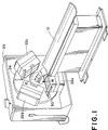
- a SPECT camera assembly includes a patient couch or support means 10 for holding a subject such as a phantom 12 or a human patient in an examination region 14.
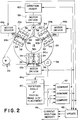
- a gantry 20 supports a plurality of gamma camera heads 22a, 22b, and 22c at regular intervals around the examination region 14, e.g. 120°. More specifically, a rotating means including a rotating drum or face plate 24 to which the camera heads are mounted and a drive motor 25 selectively rotate the camera heads around the examination region.
- Linear drive means such as motors 28a, 28b, 28c that rotate screw driver 30a, 30b, 30c, that engage followers 32a, 32b, 32c, are mounted on the reverse side of the face plate for selectively moving each gamma camera head on roller carriages 34a along tracks or guides 36 radially toward and away from the subject.
- a control means is provided for rotating the camera heads around the subject and moving the camera heads toward and away from the subject during the rotation, as is conventional in the art. More specifically, an angular position detector 38 detects the number of degrees of rotation of the plate 24 from an arbitrary 0° origin.
- a look-up table 40 is loaded with one of a plurality of selectable orbits e.g. an oval orbit of a preselected size which most closely matches the patients size. The look-up table 40 is addressed by the monitored angle to retrieve the radial distance from the center of the examination region for each camera head at that angle.
- a comparing means 42 compares the desired radial distance from the look-up table with the actual, current radial distance of each head.
- a memory update means 46 add/subtracts the distance differences with the corresponding radial position of each head in a current position memory 48 .
- This enables the camera heads to move around the subject in a circular path, an elliptical path, a peanut-shaped path, or other orbits by merely reloading the look-up table 40 from a large memory, such as a disc (not shown), of precalculated orbits.
- the symmetry in a circular path facilitates reconstruction of the collected data; whereas, the elliptical and peanut orbits move the gamma camera heads closer to the patient improving image quality.
- a radiation source 50 a line source in the FIGURE 1 embodiment, is mounted directly opposite a first of the gamma camera heads 22a and between the other two gamma camera heads 22b , 22c .
- the radiation source is selectively positionable radially either closer to or further from the first camera head 22a .
- the radiation source is disposed behind a plane of the face of the camera heads 22b and 22c such that radiation therefrom cannot impinge directly on the other camera heads 22b , 22c .
- a collimating or shield means 51 is mounted to the radiation source to limit the projection of radiation to a fan beam that intercepts the first gamma camera head 22a .
- one or more additional radiation sources 50′ may also be provided.
- the transmission radiation source may be a tube or vessel filled with a radionuclide or an active radiation generator such as an x-ray tube.
- a motor 52 rotates a screw 54 that moves a follower 56 which is mounted to move the radiation source radially.
- the control circuit controls the motor 52 such that the radiation source 50 and the first camera head 22a stay a fixed distance apart.
- Direction invertor means 60 reverses the sign or direction of movement such that a driver 58 causes the motor 52 to move the radiation source the same distance, but in the opposite radial direction relative to the center of the examination region as the driver 44a causes the motor 28a to move the first head 22a .
- the transmission radiation source 50 may be mounted to one of the adjoining heads 22b or 22c . Because movement of either head radially changes the effective angle of the fan, the reconstruction algorithm is adjusted with angular position to accommodate the changing effective fan angle.
- the effective fan angle is preferably precalculated and stored in the look-up table 40 .
- each camera head has a scintillation crystal that responds to incident radiation by producing a flash of light.
- An array of photomultiplier tubes produce electrical signals in response to each flash of light. The signals responsive to the same scintillation or flash of light are combined. The magnitude of the resultant sum is indicative of the energy of the incident radiation and the relative response of the closest photo-multiplier tubes is indicative of the spatial location of the scintillation.
- collimator 62 limits each incremental area of the scintillation crystal receiving radiation from along a fixed direction or ray, e.g. ray 64 of FIGURE 4A .
- the collimator has a plurality of vanes 66 which are directed toward a focal point, typically the transmission radiation source 50 .
- the vanes are sufficiently long that radiation impinging on the corresponding detector head is limited to radiation coming along a ray substantially from the focal point.
- the focal point and head size are selected such that a patient or subject under examination is completely encompassed within the transmission radiation fan as illustrated in FIGURE 4A.
- Conventional gamma camera heads can image radiation in two or more energy windows or ranges simultaneously.
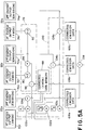
- the sum signals are sorted based on amplitude. More specifically, energy windows or ranges are defined. Each window corresponds to a photopeak or energy spectrum of a radionuclide to be used in the examination.
- the injected or emission radionuclide has one preselected energy and the radiation source 50 or transmissive radiation has a second different energy.
- the camera heads separate the transmission and emission radiation data by using the conventional energy separation circuitry used during dual injected radiopharmaceutical examinations.
- a position resolver resolves the position on the crystal, hence the ray angle, corresponding to scintillations or radiation events within one of the energy windows.
- the first head 22a has first energy level output means 70t for separating and outputting location or ray signals for each scintillation with an energy in the range of the transmission source 50 and a second energy level output means 70e for separating and outputting location or ray signals for each scintillation in the energy range of the emission radionuclide.
- the second head 22b and the third head 22c do not receive the transmission radiation directly, they do receive some of the transmission radiation by scattering and photons from other photopeak(s) of the emission source. Accordingly, the second head 22b has a transmitted energy output means 72t for separating and outputting transmission energy range data and the third head 22c has a transmitted energy output means 74t for transmission energy range data.
- a transmission radiation data correction means 76 corrects the transmission energy data from the output means 70t for emission radiation photopeak(s) in the transmission energy range.
- the transmission radiation correction means 76 includes a pair of dividers 80 and 82 which divide the output signals 72t and 74t in half, respectively.
- a summing means 84 sums these two half signals to provide a signal which is effectively the average of other emission photopeak photons received by heads 22b and 22c .
- a subtracting means 86 subtracts the average number of photons from the emission source detected in the transmission energy range by heads 22b and 22c from the transmission energy signals from head 22a .
- a corrected transmission projection data memory 88 stores the corrected transmission projection data.
- a transmission reconstruction means 90 reconstructs the transmission radiation data with a conventional CT or iterative reconstruction algorithm into a three dimensional electronic image representation stored in a three dimensional transmission radiation or attenuation image memory 92 , e.g. a fan beam reconstruction algorithm.
- Each pixel or voxel of the attenuation image memory 92 represents the radiation attenuation by a corresponding pixel or voxel of the examination region 14 or the subject being examined.
- an emission radiation event occurs at a given pixel or voxel
- one can determine the amount of radiation attenuation along the rays between the event voxel and the points on each head at which the scintillation occurs by summing the attenuation values of each pixel or voxel through which the ray passes.
- the attenuation probability of detection is the exponentiation of the negative of this sum.
- a further correction can be made by determining the distance through each intervening pixel or voxel the ray passes. When the ray extends through a pixel or voxel squarely from one face to the opposite face, the entire attenuation value is added.
- a scaling means 94 adjusts the attenuation data in accordance with the relative energy of the transmission and emission sources, e.g. the ratio or a non-linear relationship of energy.
- a major goal in transmission CT is to compute local attenuation coefficients for the object of interest.
- the recorded projection data in a transmission scan is converted to an appropriate form by taking the natural logarithm of the ratio of unattenuated acquired count per pixel or voxel (flood image N0) to observed count at a given pixel (recorded projection N).
- a conventional CT or iterative reconstruction algorithm is used to obtain the map of attenuation coefficients ⁇ ij .
- the calculated attenuation map is used to correct for the photon attenuation in the emission study.
- Another scaling method is applied to the higher energy (140 kev) attenuation map.
- This method uses a look-up table of the linear attenuation coefficients for different materials at both 75 kev and 140 kev.
- a data interpolation technique is used to determine the scaling factor to transform the attenuation distribution at 140 kev to that at 75 kev.
- the second head similarly has an emission energy location or ray signal output means 72e and the third head 22c has an emission energy ray signal output 74e . Some of the transmission photons and scattered emission photons are detected within the emission radiation energy range.
- An emission radiation correction means 100 removes the component of the measured emission radiation which is attributable to the transmission radiation.
- the emission radiation correcting means 100 includes a first multiplying means 102a for multiplying the corrected first detector head transmission radiation signal from memory 88 by a scaling factor F1.
- a second multiplying means 102b multiplies the corrected transmission radiation signal corresponding to the first detector head from the corrected transmission data memory 88 by a second scaling factor F2 and a third multiplying means 102c multiplies the corrected transmission signal from the memory 88 by a third scaling factor F3.
- the scaling factors F1, F2, F3 are determined from initial calibration tests. The tests begin with collecting pure transmission data using a cold phantom, i.e. no emission source.
- the correction factors F1, F2, F3 are determined for each head by calculating a ratio of the counts in the emission and transmission energy windows or ranges.
- Subtraction circuits 104a , 104b , 104c subtract the product of the transmission radiation value and the corresponding correction factor from the actual measured emission radiation projection data.
- Corrected emission ray or location signal memories 106a , 106b , and 106c store the corrected emission projection data from heads 22a , 22b , 22c , respectively.
- a combining circuit 108 combines the corrected emission data from heads 22a , 22b , and 22c .
- the combining circuitry combines data from each head representing the same ray. That is, the collimator 62 defines the path, relative to the head, along which radiation travelled to cause scintillation at the monitored location on the head. The location on the head and the angle of the head when the event was monitored define the ray or path between the corresponding emission source and the point of receipt.
- the corrected emission projection data from the combining means 108 is stored in a total emission projection data memory 110 .
- An emission data reconstruction processor 112 reconstructs the emission data into a corresponding three dimensional image representation which is stored in an emission image memory 114 .
- a video display terminal 116 or other display means provides a man-readable display of the reconstructed emission distribution. Typically, various displays will be selected, such as transverse or lateral slices through the patient, or even a three dimensional prospective representation.
- An attenuation correction means 118 corrects the emission data P km from total emission projection data memory 110 for attenuation by iterative reconstruction algorithms or means and provides corrected emission projection data to the emission data reconstruction means.
- the attenuation factor A km ij is the exponential of the line integral of the attenuation coefficient ⁇ ij from b ij , the entry point of projection ray to the pixel (i,j), to the detector. If no attenuation correction is needed, the attenuation coefficient ⁇ ij is set to be zero.
- the attenuation correction means 118 includes an attenuation factor calculating means 120 which calculates the attenuation factors A km ij .
- the attenuation factor calculating means calculates the exponential of the line integral of the scaled attenuation coefficients ⁇ ij along each ray k at angle ⁇ m between pixel (i,j) and the detector head.
- zero values for rays that do not intersect the pixel need not be stored.
- a weighting factor calculating means 122 calculates the weighting factors W km ij in accordance with Equation (3c) for each emission data ray k and angle ⁇ m and each pixel (i,j) of the emission distribution image memory 114 .
- the calculated weighting factors are stored in an attenuation weighting factor memory or look-up table 124 .
- the emission data reconstruction means 112 performs the multiplication and summing of Equation (3b) to generate the image values X ij at each iteration in accordance with the iterative scheme of Equation (4).
- the subject region is divided into small pixels.
- an emission radionuclide concentration and a projection radiation attenuation coefficient are determined, these parameters can be estimated by maximizing the likelihood (probability of observations).
- the preferred algorithm includes a technique for computing maximum likelihood estimates. This algorithm has the unique ability to model the Poisson nature of photon counting and the physical differences between transmission and emission tomography.
- photon attenuation and variation of resolution with depth can be treated appropriately and the use of an accurate statistical model can improve the quality of reconstruction with low counts.
- the combination of good statistical and physical models should produce superior reconstructions.
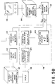
- the emission and transmission radiation may be sensed with the same energy range or window.
- Head 22a receives both the transmission and emission radiation; whereas, heads 22b and 22c receive the emission radiation.
- the heads 22a , 22b , and 22c have outputs 130a , 130b , and 130c , respectively, for outputting the common energy range radiation data.
- a transmission data correction means 132 corrects the data from output 130a in accordance with each emission data output from detector head outputs 130b and 130c . More specifically, the transmission data correcting means includes dividers 134 and 136 which divide the data from outputs 130b and 130c in half and an adding means 138 which combines the two halves to generate an average of the data received by the second and third heads.
- a subtraction means 140 subtracts the average data received by the second and third heads from the data received by the first head 22a to generate corrected transmission projection data which is stored in a corrected transmission data memory means 88′ .
- a transmission data reconstruction means 90′ reconstructs the corrected transmission data from the corrected data transmission memory means 88′ to generate attenuation image data which is stored in an attenuation image memory means 92′ .
- An emission data combining means 108′ combines emission data from the second and third heads and stores the emission data in an emission data memory means 110′ .
- An attenuation correction means 118′ corrects the emission data in accordance with the attenuation data as described above in conjunction with the two energy embodiment.
- An emission data reconstruction means 112′ reconstructs the corrected emission data to generate an emission source distribution image which is stored in an emission source distribution memory means 114′ .
- more accurate gamma camera images can be reconstructed when the collimators focus on the region of interest to be imaged within the subject.
- Better emission images can be generated by moving the focal point of the collimators closer to the center of the patient.
- the transmission radiation source is moved closer to the patient, part of the patient, at some angles, falls outside of the transmission fan, i.e. there is a truncation of part of the subject.
- the truncated region of the body tends to cause a ring artifact of analogous diameter around the reconstructed image.
- One solution is to use different collimators on head 22a , that receives both emission and transmission radiation from heads 22b and 22c which receive only the emission radiation. That is, the emission only heads have collimators with a relatively short focal length, e.g. 50 cm., and the head 22a which receives both transmission and emission radiation has a longer focal length, e.g. 110 cm.
- the oval cross-section of a human patient which is only moderately truncated provides sufficient data to calculate the attenuation coefficient factors for the EM iterative construction algorithm and analogous algorithms to solve the transmission reconstruction problem as a solution to a system of linear equations. Even though the transmission image is distorted, the attenuation factors A km ij (the exponentiation of the partial line integrals of the attenuation distribution ⁇ ij ) are measured accurate enough for those attenuation factors that have the greatest influence from the emission measurements.
- the transmission radiation source is a rectangular bar source which projects a fan beam or which is restricted to generate a fan beam of transmitted radiation toward a fan beam collimator mounted on the opposite detector head.
- the radiation source is a point source which is restricted to direct a cone or pyramid of transmission radiation toward the oppositely disposed detector head.
- a cone beam collimator has tunnels which focus to a focal point at some distance from its surface.
- the radiation source is a small flat rectangular source or a disk source and the collimator a cone beam collimator.
- the transmission radiation source is a line source and an astigmatic collimator is used which places the focal point at two different focal lines.
- a flood source and a parallel collimator are used.
Landscapes
- Health & Medical Sciences (AREA)
- Life Sciences & Earth Sciences (AREA)
- Engineering & Computer Science (AREA)
- Medical Informatics (AREA)
- Physics & Mathematics (AREA)
- High Energy & Nuclear Physics (AREA)
- Molecular Biology (AREA)
- Biomedical Technology (AREA)
- General Health & Medical Sciences (AREA)
- Nuclear Medicine, Radiotherapy & Molecular Imaging (AREA)
- Optics & Photonics (AREA)
- Heart & Thoracic Surgery (AREA)
- Veterinary Medicine (AREA)
- Pathology (AREA)
- Surgery (AREA)
- Animal Behavior & Ethology (AREA)
- Biophysics (AREA)
- Public Health (AREA)
- Radiology & Medical Imaging (AREA)
- General Physics & Mathematics (AREA)
- Spectroscopy & Molecular Physics (AREA)
- Theoretical Computer Science (AREA)
- Computer Vision & Pattern Recognition (AREA)
- Nuclear Medicine (AREA)
- Image Processing (AREA)
- Image Analysis (AREA)
Applications Claiming Priority (2)
| Application Number | Priority Date | Filing Date | Title |
|---|---|---|---|
| US712676 | 1991-06-10 | ||
| US07/712,676 US5210421A (en) | 1991-06-10 | 1991-06-10 | Simultaneous transmission and emission converging tomography |
Publications (3)
| Publication Number | Publication Date |
|---|---|
| EP0526970A2 true EP0526970A2 (de) | 1993-02-10 |
| EP0526970A3 EP0526970A3 (en) | 1993-11-18 |
| EP0526970B1 EP0526970B1 (de) | 2001-08-29 |
Family
ID=24863084
Family Applications (1)
| Application Number | Title | Priority Date | Filing Date |
|---|---|---|---|
| EP92305165A Expired - Lifetime EP0526970B1 (de) | 1991-06-10 | 1992-06-05 | Bilderzeugungsgerät und Verfahren |
Country Status (3)
| Country | Link |
|---|---|
| US (1) | US5210421A (de) |
| EP (1) | EP0526970B1 (de) |
| JP (1) | JP3128634B2 (de) |
Cited By (19)
| Publication number | Priority date | Publication date | Assignee | Title |
|---|---|---|---|---|
| FR2697918A1 (fr) * | 1992-11-10 | 1994-05-13 | Gen Electric | Dispositif de scintigraphie. |
| EP0627702A1 (de) * | 1993-06-02 | 1994-12-07 | Commissariat A L'energie Atomique | Verfahren und Vorrichtung zur Wiederherstellung von dreidimensionalen Bildern |
| EP0649117A2 (de) * | 1993-10-15 | 1995-04-19 | George S. Allen | Verfahren zur Herstellung von medizinische Bilder |
| EP0654684A2 (de) * | 1993-11-19 | 1995-05-24 | Picker International, Inc. | Nuklearkamerasystem |
| EP0741308A1 (de) * | 1995-05-04 | 1996-11-06 | Commissariat A L'energie Atomique | Vorrichtung zur Erlangen von Emissionskoordinaten eines Körper mit Dämpfungskorrigierung |
| EP0751485A1 (de) * | 1995-06-30 | 1997-01-02 | Commissariat A L'energie Atomique | Verfahren zur Herstellung ein Flussführungsvorrichtung zur Gewinnung eines Transmissionbildes von einem Objekt |
| WO1997000044A1 (en) * | 1995-06-16 | 1997-01-03 | Siemens Medical Systems, Inc. | Line source for attenuation correction in nuclear medicine studies and apparatus and methods for using the source |
| EP0782009A1 (de) * | 1994-06-15 | 1997-07-02 | Smv International | Verfahren zur Erzeugung eines Übertragungsbildes in Nuklearmedizin |
| NL1003081C2 (nl) * | 1996-05-10 | 1997-11-18 | Frederik Johannes Beekman | Convergerende collimatoren gecombineerd met bewegende energievensters en virtueel kleine puntbronnen voor het maken van betere transmissieopnamen van objecten die gammastraling uitzenden. |
| FR2752948A1 (fr) * | 1996-09-05 | 1998-03-06 | Smv Int | Acquisition simultanee de coups transmis et de coups emis pour une gamma camera |
| WO2001061326A2 (de) * | 2000-02-17 | 2001-08-23 | Macrotron Process Technologies Gmbh | Röntgensystem |
| EP1237012A2 (de) * | 2001-02-28 | 2002-09-04 | Anzai Medical Kabushiki Kaisha | Verfahren und Vorrichtung zur Detektion der Strahlungsquelle |
| EP1316818A2 (de) * | 2001-12-03 | 2003-06-04 | Hitachi, Ltd. | Röntgenabbildungsvorrichtung |
| US8116427B2 (en) | 2001-12-03 | 2012-02-14 | Hitachi, Ltd. | Radiological imaging apparatus |
| WO2015152720A3 (en) * | 2014-04-02 | 2015-11-26 | Milabs B.V. | Scanning of a human body part with high-energy radiation emitted by the body part |
| US9943278B2 (en) | 2004-06-01 | 2018-04-17 | Spectrum Dynamics Medical Limited | Radioactive-emission-measurement optimization to specific body structures |
| US9943274B2 (en) | 2004-11-09 | 2018-04-17 | Spectrum Dynamics Medical Limited | Radioimaging using low dose isotope |
| CN110361770A (zh) * | 2019-07-19 | 2019-10-22 | 四川轻化工大学 | 扇形阵列探测器层析γ扫描核废物桶检测装置及检测方法 |
| US10964075B2 (en) | 2004-01-13 | 2021-03-30 | Spectrum Dynamics Llc | Gating with anatomically varying durations |
Families Citing this family (83)
| Publication number | Priority date | Publication date | Assignee | Title |
|---|---|---|---|---|
| US5376795A (en) * | 1990-07-09 | 1994-12-27 | Regents Of The University Of California | Emission-transmission imaging system using single energy and dual energy transmission and radionuclide emission data |
| US5481115A (en) * | 1991-06-10 | 1996-01-02 | University Of Utah, The | Electronic calibration of single photon emission computed tomography cameras |
| US5338936A (en) * | 1991-06-10 | 1994-08-16 | Thomas E. Kocovsky, Jr. | Simultaneous transmission and emission converging tomography |
| US5323007A (en) * | 1992-02-07 | 1994-06-21 | Univ. Of Chicago Development Corp. Argonne National Laboratories | Method of recovering tomographic signal elements in a projection profile or image by solving linear equations |
| US5390225A (en) * | 1992-06-29 | 1995-02-14 | Siemens Medical Systems, Inc. | Mapping slices of the human body into regions having a constant linear attenuation coefficient for correcting images acquired during a nuclear medicine study for attenuation artifacts |
| US5587585A (en) * | 1993-06-02 | 1996-12-24 | Eisen; Yosef | Light weight gamma-camera head and gamma-camera assemblies containing it |
| US5939724A (en) * | 1993-06-02 | 1999-08-17 | State Of Israel, The, Atomic Energy Commission, Soreo Nuclear Research Center | Light weight-camera head and-camera assemblies containing it |
| IL105881A (en) * | 1993-06-02 | 1995-10-31 | Israel State | A lightweight head for a gamma camera and a gamma camera assembly that includes it |
| US5449913A (en) * | 1993-11-03 | 1995-09-12 | Chang; Wei | Apparatus for producing attenuation scan |
| US5391877A (en) * | 1994-01-26 | 1995-02-21 | Marks; Michael A. | Combined imaging scanner |
| US5552605A (en) * | 1994-11-18 | 1996-09-03 | Picker International, Inc. | Motion correction based on reprojection data |
| US5532490A (en) * | 1994-12-27 | 1996-07-02 | The University Of Utah | Displaced center-of-rotation fan-beam tomography for cardiac imaging |
| US5600145A (en) * | 1995-01-19 | 1997-02-04 | Picker International, Inc. | Emission/transmission device for use with a dual head nuclear medicine gamma camera with the transmission source located behind the emission collimator |
| US5598003A (en) * | 1995-05-11 | 1997-01-28 | Adac Laboratories | Large field of view transmission and small field of view emission scan within gamma camera system |
| US7110587B1 (en) * | 1995-05-31 | 2006-09-19 | Ge Medical Systems Israel Ltd. | Registration of nuclear medicine images |
| US5871013A (en) * | 1995-05-31 | 1999-02-16 | Elscint Ltd. | Registration of nuclear medicine images |
| US5650625A (en) * | 1995-06-16 | 1997-07-22 | Siemens Medical Systems, Inc. | Two-dimensional radiation emitter for attenuation correction in nuclear medicine studies |
| JPH095443A (ja) * | 1995-06-23 | 1997-01-10 | Toshiba Corp | 核医学診断装置 |
| US5625660A (en) * | 1995-06-30 | 1997-04-29 | Picker International, Inc. | Image reconstruction from helical partial cone-beam data |
| US5565684A (en) * | 1995-06-30 | 1996-10-15 | The University Of Utah | Three-dimensional SPECT reconstruction of combined cone-beam and fan-beam data |
| JP3373720B2 (ja) * | 1996-03-25 | 2003-02-04 | 株式会社日立メディコ | X線断層撮影装置 |
| US5672877A (en) * | 1996-03-27 | 1997-09-30 | Adac Laboratories | Coregistration of multi-modality data in a medical imaging system |
| US5834780A (en) * | 1996-05-29 | 1998-11-10 | Picker International, Inc. | Scanning line source for gamma camera |
| US6171243B1 (en) * | 1997-05-30 | 2001-01-09 | Picker International, Inc. | Combination of collimated and coincidence information for positron imaging |
| US5909476A (en) * | 1997-09-22 | 1999-06-01 | University Of Iowa Research Foundation | Iterative process for reconstructing cone-beam tomographic images |
| US6539103B1 (en) * | 1997-11-12 | 2003-03-25 | The University Of Utah | Method and apparatus for image reconstruction using a knowledge set |
| US6381349B1 (en) | 1997-11-12 | 2002-04-30 | The University Of Utah | Projector/backprojector with slice-to-slice blurring for efficient 3D scatter modeling |
| US6201247B1 (en) | 1998-04-02 | 2001-03-13 | Picker International, Inc. | Line source for gamma camera |
| JP4170449B2 (ja) | 1998-07-07 | 2008-10-22 | 株式会社東芝 | トランスミッションctのトランケーション補正装置、核医学診断装置及びトランケーション補正方法 |
| US6271524B1 (en) | 1998-08-05 | 2001-08-07 | Elgems, Ltd. | Gamma ray collimator |
| CA2252993C (en) * | 1998-11-06 | 2011-04-19 | Universite De Sherbrooke | Detector assembly for multi-modality scanners |
| US6310968B1 (en) * | 1998-11-24 | 2001-10-30 | Picker International, Inc. | Source-assisted attenuation correction for emission computed tomography |
| US6346706B1 (en) * | 1999-06-24 | 2002-02-12 | The Regents Of The University Of Michigan | High resolution photon detector |
| US8565860B2 (en) | 2000-08-21 | 2013-10-22 | Biosensors International Group, Ltd. | Radioactive emission detector equipped with a position tracking system |
| US8489176B1 (en) | 2000-08-21 | 2013-07-16 | Spectrum Dynamics Llc | Radioactive emission detector equipped with a position tracking system and utilization thereof with medical systems and in medical procedures |
| WO2004042546A1 (en) | 2002-11-04 | 2004-05-21 | V-Target Technologies Ltd. | Apparatus and methods for imaging and attenuation correction |
| US8909325B2 (en) | 2000-08-21 | 2014-12-09 | Biosensors International Group, Ltd. | Radioactive emission detector equipped with a position tracking system and utilization thereof with medical systems and in medical procedures |
| US6787777B1 (en) | 2000-11-09 | 2004-09-07 | Koninklijke Philips Electronics, N.V. | Nuclear imaging system and method using segmented field of view |
| US20020073441A1 (en) | 2000-12-13 | 2002-06-13 | Ross Brian D. | Compositions and methods for detecting proteolytic activity |
| US6965661B2 (en) | 2001-06-19 | 2005-11-15 | Hitachi, Ltd. | Radiological imaging apparatus and radiological imaging method |
| EP1347309A3 (de) * | 2002-03-20 | 2012-04-18 | Hitachi, Ltd. | Radiologische, bildgebende Vorrichtung und Verfahren |
| US7577228B2 (en) * | 2002-10-28 | 2009-08-18 | General Electric Company | Transportable manufacturing facility for radioactive materials |
| US7103233B2 (en) * | 2002-10-31 | 2006-09-05 | Ge Medical Systems Global Technology Company, Llc | Methods and apparatus for determining component alignment |
| DE602004028513D1 (de) | 2003-12-23 | 2010-09-16 | Mount Sinai Hospital Corp | Verfahren zum nachweis von mit endometrialer krankheit oder phase assoziierten markern |
| WO2006051531A2 (en) | 2004-11-09 | 2006-05-18 | Spectrum Dynamics Llc | Radioimaging |
| WO2005067383A2 (en) | 2004-01-13 | 2005-07-28 | Spectrum Dynamics Llc | Multi-dimensional image reconstruction |
| US8571881B2 (en) | 2004-11-09 | 2013-10-29 | Spectrum Dynamics, Llc | Radiopharmaceutical dispensing, administration, and imaging |
| WO2008010227A2 (en) | 2006-07-19 | 2008-01-24 | Spectrum Dynamics Llc | Imaging protocols |
| US8586932B2 (en) | 2004-11-09 | 2013-11-19 | Spectrum Dynamics Llc | System and method for radioactive emission measurement |
| US9470801B2 (en) | 2004-01-13 | 2016-10-18 | Spectrum Dynamics Llc | Gating with anatomically varying durations |
| US7323689B2 (en) * | 2004-09-24 | 2008-01-29 | Siemens Medical Solutions Usa, Inc. | Attenuation correction in nuclear medicine studies by simultaneous transmission and emission data measurement and estimation of emission-to-transmission crosstalk |
| US7397893B2 (en) * | 2004-09-27 | 2008-07-08 | Siemens Medical Solutions Usa, Inc. | Method and apparatus for simultaneous emission and transmission spect using oblique line sources |
| EP1802998B1 (de) * | 2004-10-15 | 2014-09-17 | Koninklijke Philips N.V. | Nuklearmedizinischer detektor |
| US8423125B2 (en) | 2004-11-09 | 2013-04-16 | Spectrum Dynamics Llc | Radioimaging |
| US9316743B2 (en) | 2004-11-09 | 2016-04-19 | Biosensors International Group, Ltd. | System and method for radioactive emission measurement |
| US8615405B2 (en) | 2004-11-09 | 2013-12-24 | Biosensors International Group, Ltd. | Imaging system customization using data from radiopharmaceutical-associated data carrier |
| US8013307B2 (en) * | 2004-12-17 | 2011-09-06 | Koninklijke Philips Electronics N.V. | Truncation compensation algorithm for iterative reconstruction |
| CN100450564C (zh) * | 2005-01-28 | 2009-01-14 | 深圳市海博科技有限公司 | 一种放射治疗装置 |
| EP1909853B1 (de) | 2005-07-19 | 2015-03-18 | Biosensors International Group, Ltd. | Bildgebungsprotokolle |
| US8837793B2 (en) | 2005-07-19 | 2014-09-16 | Biosensors International Group, Ltd. | Reconstruction stabilizer and active vision |
| EP1934943B1 (de) * | 2005-10-05 | 2016-05-04 | Koninklijke Philips N.V. | Verfahren und system zur rekonstruktion von pet-bildern über ersatzbilder |
| JP4604974B2 (ja) * | 2005-11-15 | 2011-01-05 | 株式会社日立製作所 | Pet装置 |
| US7348564B2 (en) * | 2005-12-12 | 2008-03-25 | General Electric Company | Multi modality imaging methods and apparatus |
| US8894974B2 (en) | 2006-05-11 | 2014-11-25 | Spectrum Dynamics Llc | Radiopharmaceuticals for diagnosis and therapy |
| US8610075B2 (en) | 2006-11-13 | 2013-12-17 | Biosensors International Group Ltd. | Radioimaging applications of and novel formulations of teboroxime |
| US9275451B2 (en) | 2006-12-20 | 2016-03-01 | Biosensors International Group, Ltd. | Method, a system, and an apparatus for using and processing multidimensional data |
| WO2009013661A2 (en) * | 2007-07-26 | 2009-01-29 | Koninklijke Philips Electronics N.V. | Motion correction in nuclear imaging |
| US8521253B2 (en) | 2007-10-29 | 2013-08-27 | Spectrum Dynamics Llc | Prostate imaging |
| JP4737201B2 (ja) * | 2008-01-15 | 2011-07-27 | 株式会社日立製作所 | 放射線検査装置 |
| CA2618163A1 (en) | 2008-02-07 | 2009-08-07 | K. W. Michael Siu | Head and neck cancer biomarkers |
| US20110060566A1 (en) * | 2008-05-21 | 2011-03-10 | Koninklijke Philips Electronics N.V. | Method and apparatus for scatter correction |
| JP5523691B2 (ja) * | 2008-10-08 | 2014-06-18 | 株式会社東芝 | X線診断装置 |
| JP2009058528A (ja) * | 2008-12-01 | 2009-03-19 | Hitachi Ltd | 放射線検査装置 |
| EP2410917B1 (de) | 2009-03-24 | 2020-05-20 | Koninklijke Philips N.V. | System und verfahren zur hybriden dual-modalität-bildverarbeitung |
| KR101711399B1 (ko) | 2009-05-27 | 2017-03-03 | 전남대학교산학협력단 | 선택적 경색 조직 타겟팅 박테리아 및 그의 용도 |
| US8338788B2 (en) | 2009-07-29 | 2012-12-25 | Spectrum Dynamics Llc | Method and system of optimized volumetric imaging |
| KR101199570B1 (ko) | 2009-09-09 | 2012-11-13 | 경북대학교 산학협력단 | 신규한 테트라아자 거대고리 화합물, 제조방법 및 그 용도 |
| US20110110570A1 (en) * | 2009-11-10 | 2011-05-12 | Avi Bar-Shalev | Apparatus and methods for generating a planar image |
| WO2011153544A1 (en) * | 2010-06-04 | 2011-12-08 | Neurologica Corp. | High resolution single photon emission computed tomography (spect) system |
| JP5532061B2 (ja) * | 2012-02-06 | 2014-06-25 | 株式会社日立製作所 | 放射線検査装置 |
| WO2015034957A1 (en) * | 2013-09-03 | 2015-03-12 | Prescient Imaging LLC | Low noise transmission scan simultaneous with positron emission tomography |
| EP3559037A1 (de) | 2016-12-22 | 2019-10-30 | Wake Forest University Health Sciences | Auf sirp-gamma abzielende mittel zur behandlung von krebs |
| CN113049612A (zh) * | 2021-03-15 | 2021-06-29 | 中国原子能科学研究院 | 一种分段伽马测量装置及测量方法 |
Citations (1)
| Publication number | Priority date | Publication date | Assignee | Title |
|---|---|---|---|---|
| WO1991000048A2 (en) * | 1989-06-30 | 1991-01-10 | Kaplan H Charles | Transmission/emission registered image (teri) computed tomography scanners |
Family Cites Families (2)
| Publication number | Priority date | Publication date | Assignee | Title |
|---|---|---|---|---|
| US4670657A (en) * | 1985-03-29 | 1987-06-02 | Siemens Gammasonics, Inc. | Astigmatic collimator |
| JPH0619439B2 (ja) * | 1989-08-04 | 1994-03-16 | 株式会社東芝 | Spect装置 |
-
1991
- 1991-06-10 US US07/712,676 patent/US5210421A/en not_active Expired - Lifetime
-
1992
- 1992-06-05 EP EP92305165A patent/EP0526970B1/de not_active Expired - Lifetime
- 1992-06-09 JP JP04174823A patent/JP3128634B2/ja not_active Expired - Fee Related
Patent Citations (1)
| Publication number | Priority date | Publication date | Assignee | Title |
|---|---|---|---|---|
| WO1991000048A2 (en) * | 1989-06-30 | 1991-01-10 | Kaplan H Charles | Transmission/emission registered image (teri) computed tomography scanners |
Non-Patent Citations (3)
| Title |
|---|
| European Journal of Nuclear Medicine, Vol. 16, No. 8-10, 1990, West Germany, pages 587-594; ALMQUIST et al.: "Quantitative spect by attenuation correction of the projection set using transmission data: evaluation of a method". * |
| IEEE Transaction on Nuclear Science, Vol. 36, No. 1, February 1989, USA, pages 1011-1016; THOMPSON et al.: "Simultaneous transmission and emission scans in positron emission tomography". * |
| IEEE Transaction on Nuclear Science, Vol. 37, No. 2, April 1990, USA, pages 600-608; MANGLOS et al.: "Attenuation maps for spect determined using cone beam transmission computed tomography", paragraph I. * |
Cited By (38)
| Publication number | Priority date | Publication date | Assignee | Title |
|---|---|---|---|---|
| US5479021A (en) * | 1991-06-10 | 1995-12-26 | Picker International, Inc. | Transmission line source assembly for spect cameras |
| FR2697918A1 (fr) * | 1992-11-10 | 1994-05-13 | Gen Electric | Dispositif de scintigraphie. |
| EP0627702A1 (de) * | 1993-06-02 | 1994-12-07 | Commissariat A L'energie Atomique | Verfahren und Vorrichtung zur Wiederherstellung von dreidimensionalen Bildern |
| FR2706043A1 (fr) * | 1993-06-02 | 1994-12-09 | Commissariat Energie Atomique | Installation et procédé de reconstruction d'images tridimensionnelles. |
| US5933517A (en) * | 1993-06-02 | 1999-08-03 | Commissariat A L'energie Atomique | Installation and process for the reconstruction of three-dimensional images |
| EP0649117A2 (de) * | 1993-10-15 | 1995-04-19 | George S. Allen | Verfahren zur Herstellung von medizinische Bilder |
| EP0649117A3 (de) * | 1993-10-15 | 1996-01-31 | George S Allen | Verfahren zur Herstellung von medizinische Bilder. |
| US5590215A (en) * | 1993-10-15 | 1996-12-31 | Allen; George S. | Method for providing medical images |
| EP0654684A2 (de) * | 1993-11-19 | 1995-05-24 | Picker International, Inc. | Nuklearkamerasystem |
| EP0654684A3 (de) * | 1993-11-19 | 1995-09-06 | Picker Int Inc | Nuklearkamerasystem. |
| EP0782009A1 (de) * | 1994-06-15 | 1997-07-02 | Smv International | Verfahren zur Erzeugung eines Übertragungsbildes in Nuklearmedizin |
| US5814817A (en) * | 1995-05-04 | 1998-09-29 | Commissariat A L'energie Atomique | Process for carrying out emission cartography of a body corrected with respect to the attenuation by said body |
| FR2733841A1 (fr) * | 1995-05-04 | 1996-11-08 | Commissariat Energie Atomique | Procede de realisation de la cartographie d'emission d'un corps corrigee de l'attenuation par ce corps |
| EP0741308A1 (de) * | 1995-05-04 | 1996-11-06 | Commissariat A L'energie Atomique | Vorrichtung zur Erlangen von Emissionskoordinaten eines Körper mit Dämpfungskorrigierung |
| WO1997000044A1 (en) * | 1995-06-16 | 1997-01-03 | Siemens Medical Systems, Inc. | Line source for attenuation correction in nuclear medicine studies and apparatus and methods for using the source |
| FR2736178A1 (fr) * | 1995-06-30 | 1997-01-03 | Commissariat Energie Atomique | Procede d'acquisition d'images en transmission d'un corps soumis a un rayonnement |
| EP0751485A1 (de) * | 1995-06-30 | 1997-01-02 | Commissariat A L'energie Atomique | Verfahren zur Herstellung ein Flussführungsvorrichtung zur Gewinnung eines Transmissionbildes von einem Objekt |
| US6324258B1 (en) | 1996-05-10 | 2001-11-27 | Academisch Ziekenhuis Utrecht | Apparatus for making tomographic images |
| NL1003081C2 (nl) * | 1996-05-10 | 1997-11-18 | Frederik Johannes Beekman | Convergerende collimatoren gecombineerd met bewegende energievensters en virtueel kleine puntbronnen voor het maken van betere transmissieopnamen van objecten die gammastraling uitzenden. |
| WO1997043667A1 (en) * | 1996-05-10 | 1997-11-20 | Academisch Ziekenhuis Utrecht | Apparatus for making tomographic images |
| AU730166B2 (en) * | 1996-05-10 | 2001-03-01 | Academisch Ziekenhuis Utrecht | Apparatus for making tomography images |
| FR2752948A1 (fr) * | 1996-09-05 | 1998-03-06 | Smv Int | Acquisition simultanee de coups transmis et de coups emis pour une gamma camera |
| US6194724B1 (en) | 1996-09-05 | 2001-02-27 | Smv International | Simultaneous acquisition of transmitted counts and emitted counts for a gamma camera |
| WO2001061326A3 (de) * | 2000-02-17 | 2002-05-23 | Macrotron Process Technologies | Röntgensystem |
| WO2001061326A2 (de) * | 2000-02-17 | 2001-08-23 | Macrotron Process Technologies Gmbh | Röntgensystem |
| EP1237012A2 (de) * | 2001-02-28 | 2002-09-04 | Anzai Medical Kabushiki Kaisha | Verfahren und Vorrichtung zur Detektion der Strahlungsquelle |
| EP1237012A3 (de) * | 2001-02-28 | 2005-03-16 | Anzai Medical Kabushiki Kaisha | Verfahren und Vorrichtung zur Detektion der Strahlungsquelle |
| EP1316818A2 (de) * | 2001-12-03 | 2003-06-04 | Hitachi, Ltd. | Röntgenabbildungsvorrichtung |
| US8116427B2 (en) | 2001-12-03 | 2012-02-14 | Hitachi, Ltd. | Radiological imaging apparatus |
| EP1316818A3 (de) * | 2001-12-03 | 2012-04-11 | Hitachi, Ltd. | Röntgenabbildungsvorrichtung |
| US10964075B2 (en) | 2004-01-13 | 2021-03-30 | Spectrum Dynamics Llc | Gating with anatomically varying durations |
| US9943278B2 (en) | 2004-06-01 | 2018-04-17 | Spectrum Dynamics Medical Limited | Radioactive-emission-measurement optimization to specific body structures |
| US9943274B2 (en) | 2004-11-09 | 2018-04-17 | Spectrum Dynamics Medical Limited | Radioimaging using low dose isotope |
| US10136865B2 (en) | 2004-11-09 | 2018-11-27 | Spectrum Dynamics Medical Limited | Radioimaging using low dose isotope |
| US9610051B2 (en) | 2014-04-02 | 2017-04-04 | Milabs B.V. | Scanning of a human body part with high-energy radiation emitted by the body part |
| WO2015152720A3 (en) * | 2014-04-02 | 2015-11-26 | Milabs B.V. | Scanning of a human body part with high-energy radiation emitted by the body part |
| CN110361770A (zh) * | 2019-07-19 | 2019-10-22 | 四川轻化工大学 | 扇形阵列探测器层析γ扫描核废物桶检测装置及检测方法 |
| CN110361770B (zh) * | 2019-07-19 | 2023-01-10 | 四川轻化工大学 | 扇形阵列探测器层析γ扫描核废物桶检测装置及检测方法 |
Also Published As
| Publication number | Publication date |
|---|---|
| US5210421A (en) | 1993-05-11 |
| EP0526970B1 (de) | 2001-08-29 |
| JPH05302979A (ja) | 1993-11-16 |
| EP0526970A3 (en) | 1993-11-18 |
| JP3128634B2 (ja) | 2001-01-29 |
Similar Documents
| Publication | Publication Date | Title |
|---|---|---|
| EP0526970B1 (de) | Bilderzeugungsgerät und Verfahren | |
| US5338936A (en) | Simultaneous transmission and emission converging tomography | |
| US5565684A (en) | Three-dimensional SPECT reconstruction of combined cone-beam and fan-beam data | |
| EP1006370B1 (de) | Verfahren zur Bildrekonstruktion für Tomographie | |
| US5903008A (en) | Scatter correction methods and systems in single photon emission computed tomography | |
| US6388244B1 (en) | Virtual contouring for transmission scanning in spect and pet studies | |
| Jaszczak et al. | SPECT: Single photon emission computed tomography | |
| US5376795A (en) | Emission-transmission imaging system using single energy and dual energy transmission and radionuclide emission data | |
| US5923038A (en) | Partial angle tomography scanning and reconstruction | |
| US8013307B2 (en) | Truncation compensation algorithm for iterative reconstruction | |
| US5818050A (en) | Collimator-free photon tomography | |
| US6762413B2 (en) | Correction for depth-dependent sensitivity in rotating slat-collimated gamma camera | |
| US6040580A (en) | Method and apparatus for forming multi-dimensional attenuation correction data in tomography applications | |
| US6211523B1 (en) | Autocontouring device for gamma camera using radioactive source and transverse motion | |
| US6661865B1 (en) | Variable axial shielding for pet imaging | |
| EP0648341B1 (de) | Spect-artifakt-korrekturverfahren für die änderungskompensation der dämpfungskoeffizienten durch wiederherstellung eines streubildes | |
| US6429433B1 (en) | Continuous rotation sampling scheme for transmission radiation corrected gamma cameras | |
| US4984159A (en) | Method and apparatus for estimating elliptical body contours in fan beam computed tomographic systems | |
| US6539103B1 (en) | Method and apparatus for image reconstruction using a knowledge set | |
| US5739540A (en) | Nuclear medicine diagnostic apparatus | |
| JPH11299768A (ja) | X線ct装置 | |
| US6388257B1 (en) | Stepped asymmetric sampling scheme for transmission radiation corrected gamma cameras | |
| US5814817A (en) | Process for carrying out emission cartography of a body corrected with respect to the attenuation by said body | |
| Wegmann et al. | Investigation of the scatter contribution in single photon transmission measurements by means of Monte Carlo simulations | |
| EP0910280B1 (de) | Computergesteuerter tomograph zur volumenabtastung |
Legal Events
| Date | Code | Title | Description |
|---|---|---|---|
| PUAI | Public reference made under article 153(3) epc to a published international application that has entered the european phase |
Free format text: ORIGINAL CODE: 0009012 |
|
| AK | Designated contracting states |
Kind code of ref document: A2 Designated state(s): FR GB NL |
|
| PUAL | Search report despatched |
Free format text: ORIGINAL CODE: 0009013 |
|
| AK | Designated contracting states |
Kind code of ref document: A3 Designated state(s): FR GB NL |
|
| 17P | Request for examination filed |
Effective date: 19940511 |
|
| 17Q | First examination report despatched |
Effective date: 19960702 |
|
| RIC1 | Information provided on ipc code assigned before grant |
Free format text: 7A 61B 6/00 A, 7G 01T 1/29 B, 7G 06T 11/00 B |
|
| GRAG | Despatch of communication of intention to grant |
Free format text: ORIGINAL CODE: EPIDOS AGRA |
|
| GRAG | Despatch of communication of intention to grant |
Free format text: ORIGINAL CODE: EPIDOS AGRA |
|
| GRAH | Despatch of communication of intention to grant a patent |
Free format text: ORIGINAL CODE: EPIDOS IGRA |
|
| RAP1 | Party data changed (applicant data changed or rights of an application transferred) |
Owner name: THE UNIVERSITY OF UTAH Owner name: MARCONI MEDICAL SYSTEMS, INC. |
|
| GRAH | Despatch of communication of intention to grant a patent |
Free format text: ORIGINAL CODE: EPIDOS IGRA |
|
| GRAA | (expected) grant |
Free format text: ORIGINAL CODE: 0009210 |
|
| AK | Designated contracting states |
Kind code of ref document: B1 Designated state(s): FR GB NL |
|
| ET | Fr: translation filed | ||
| REG | Reference to a national code |
Ref country code: GB Ref legal event code: IF02 |
|
| PLBE | No opposition filed within time limit |
Free format text: ORIGINAL CODE: 0009261 |
|
| STAA | Information on the status of an ep patent application or granted ep patent |
Free format text: STATUS: NO OPPOSITION FILED WITHIN TIME LIMIT |
|
| 26N | No opposition filed | ||
| PGFP | Annual fee paid to national office [announced via postgrant information from national office to epo] |
Ref country code: NL Payment date: 20030513 Year of fee payment: 12 |
|
| REG | Reference to a national code |
Ref country code: GB Ref legal event code: 732E |
|
| REG | Reference to a national code |
Ref country code: FR Ref legal event code: CD |
|
| REG | Reference to a national code |
Ref country code: GB Ref legal event code: 746 Effective date: 20040504 |
|
| REG | Reference to a national code |
Ref country code: FR Ref legal event code: TQ |
|
| PG25 | Lapsed in a contracting state [announced via postgrant information from national office to epo] |
Ref country code: NL Free format text: LAPSE BECAUSE OF NON-PAYMENT OF DUE FEES Effective date: 20050101 |
|
| NLV4 | Nl: lapsed or anulled due to non-payment of the annual fee |
Effective date: 20050101 |
|
| PGFP | Annual fee paid to national office [announced via postgrant information from national office to epo] |
Ref country code: FR Payment date: 20090626 Year of fee payment: 18 |
|
| PGFP | Annual fee paid to national office [announced via postgrant information from national office to epo] |
Ref country code: GB Payment date: 20090630 Year of fee payment: 18 |
|
| GBPC | Gb: european patent ceased through non-payment of renewal fee |
Effective date: 20100605 |
|
| REG | Reference to a national code |
Ref country code: FR Ref legal event code: ST Effective date: 20110228 |
|
| PG25 | Lapsed in a contracting state [announced via postgrant information from national office to epo] |
Ref country code: FR Free format text: LAPSE BECAUSE OF NON-PAYMENT OF DUE FEES Effective date: 20100630 |
|
| PG25 | Lapsed in a contracting state [announced via postgrant information from national office to epo] |
Ref country code: GB Free format text: LAPSE BECAUSE OF NON-PAYMENT OF DUE FEES Effective date: 20100605 |