EP4145643A1 - Adaptation d'un actionneur polyvalent - Google Patents
Adaptation d'un actionneur polyvalent Download PDFInfo
- Publication number
- EP4145643A1 EP4145643A1 EP22200267.7A EP22200267A EP4145643A1 EP 4145643 A1 EP4145643 A1 EP 4145643A1 EP 22200267 A EP22200267 A EP 22200267A EP 4145643 A1 EP4145643 A1 EP 4145643A1
- Authority
- EP
- European Patent Office
- Prior art keywords
- component
- connector
- actuator
- universal
- housing
- Prior art date
- Legal status (The legal status is an assumption and is not a legal conclusion. Google has not performed a legal analysis and makes no representation as to the accuracy of the status listed.)
- Pending
Links
- 230000008878 coupling Effects 0.000 claims abstract description 32
- 238000010168 coupling process Methods 0.000 claims abstract description 32
- 238000005859 coupling reaction Methods 0.000 claims abstract description 32
- 238000004891 communication Methods 0.000 claims description 9
- ONNCPBRWFSKDMQ-UHFFFAOYSA-N 2,3',5-trichlorobiphenyl Chemical compound ClC1=CC=CC(C=2C(=CC=C(Cl)C=2)Cl)=C1 ONNCPBRWFSKDMQ-UHFFFAOYSA-N 0.000 description 6
- 239000003507 refrigerant Substances 0.000 description 6
- 239000004020 conductor Substances 0.000 description 4
- 239000002826 coolant Substances 0.000 description 4
- 238000004519 manufacturing process Methods 0.000 description 4
- 239000000463 material Substances 0.000 description 3
- 238000000034 method Methods 0.000 description 3
- 239000012530 fluid Substances 0.000 description 2
- 230000008569 process Effects 0.000 description 2
- 239000000654 additive Substances 0.000 description 1
- 230000000996 additive effect Effects 0.000 description 1
- 230000001419 dependent effect Effects 0.000 description 1
- 238000012423 maintenance Methods 0.000 description 1
- 238000012986 modification Methods 0.000 description 1
- 230000004048 modification Effects 0.000 description 1
- 238000000465 moulding Methods 0.000 description 1
- 238000004806 packaging method and process Methods 0.000 description 1
- 230000008439 repair process Effects 0.000 description 1
- 238000012546 transfer Methods 0.000 description 1
Images


Classifications
-
- H—ELECTRICITY
- H01—ELECTRIC ELEMENTS
- H01R—ELECTRICALLY-CONDUCTIVE CONNECTIONS; STRUCTURAL ASSOCIATIONS OF A PLURALITY OF MUTUALLY-INSULATED ELECTRICAL CONNECTING ELEMENTS; COUPLING DEVICES; CURRENT COLLECTORS
- H01R12/00—Structural associations of a plurality of mutually-insulated electrical connecting elements, specially adapted for printed circuits, e.g. printed circuit boards [PCB], flat or ribbon cables, or like generally planar structures, e.g. terminal strips, terminal blocks; Coupling devices specially adapted for printed circuits, flat or ribbon cables, or like generally planar structures; Terminals specially adapted for contact with, or insertion into, printed circuits, flat or ribbon cables, or like generally planar structures
- H01R12/70—Coupling devices
- H01R12/7005—Guiding, mounting, polarizing or locking means; Extractors
- H01R12/7011—Locking or fixing a connector to a PCB
- H01R12/7017—Snap means
- H01R12/7023—Snap means integral with the coupling device
-
- H—ELECTRICITY
- H01—ELECTRIC ELEMENTS
- H01R—ELECTRICALLY-CONDUCTIVE CONNECTIONS; STRUCTURAL ASSOCIATIONS OF A PLURALITY OF MUTUALLY-INSULATED ELECTRICAL CONNECTING ELEMENTS; COUPLING DEVICES; CURRENT COLLECTORS
- H01R13/00—Details of coupling devices of the kinds covered by groups H01R12/70 or H01R24/00 - H01R33/00
- H01R13/02—Contact members
- H01R13/20—Pins, blades, or sockets shaped, or provided with separate member, to retain co-operating parts together
-
- F—MECHANICAL ENGINEERING; LIGHTING; HEATING; WEAPONS; BLASTING
- F16—ENGINEERING ELEMENTS AND UNITS; GENERAL MEASURES FOR PRODUCING AND MAINTAINING EFFECTIVE FUNCTIONING OF MACHINES OR INSTALLATIONS; THERMAL INSULATION IN GENERAL
- F16K—VALVES; TAPS; COCKS; ACTUATING-FLOATS; DEVICES FOR VENTING OR AERATING
- F16K27/00—Construction of housing; Use of materials therefor
- F16K27/04—Construction of housing; Use of materials therefor of sliding valves
-
- F—MECHANICAL ENGINEERING; LIGHTING; HEATING; WEAPONS; BLASTING
- F16—ENGINEERING ELEMENTS AND UNITS; GENERAL MEASURES FOR PRODUCING AND MAINTAINING EFFECTIVE FUNCTIONING OF MACHINES OR INSTALLATIONS; THERMAL INSULATION IN GENERAL
- F16K—VALVES; TAPS; COCKS; ACTUATING-FLOATS; DEVICES FOR VENTING OR AERATING
- F16K27/00—Construction of housing; Use of materials therefor
- F16K27/06—Construction of housing; Use of materials therefor of taps or cocks
-
- F—MECHANICAL ENGINEERING; LIGHTING; HEATING; WEAPONS; BLASTING
- F16—ENGINEERING ELEMENTS AND UNITS; GENERAL MEASURES FOR PRODUCING AND MAINTAINING EFFECTIVE FUNCTIONING OF MACHINES OR INSTALLATIONS; THERMAL INSULATION IN GENERAL
- F16K—VALVES; TAPS; COCKS; ACTUATING-FLOATS; DEVICES FOR VENTING OR AERATING
- F16K31/00—Actuating devices; Operating means; Releasing devices
- F16K31/02—Actuating devices; Operating means; Releasing devices electric; magnetic
- F16K31/04—Actuating devices; Operating means; Releasing devices electric; magnetic using a motor
- F16K31/041—Actuating devices; Operating means; Releasing devices electric; magnetic using a motor for rotating valves
-
- F—MECHANICAL ENGINEERING; LIGHTING; HEATING; WEAPONS; BLASTING
- F16—ENGINEERING ELEMENTS AND UNITS; GENERAL MEASURES FOR PRODUCING AND MAINTAINING EFFECTIVE FUNCTIONING OF MACHINES OR INSTALLATIONS; THERMAL INSULATION IN GENERAL
- F16K—VALVES; TAPS; COCKS; ACTUATING-FLOATS; DEVICES FOR VENTING OR AERATING
- F16K31/00—Actuating devices; Operating means; Releasing devices
- F16K31/02—Actuating devices; Operating means; Releasing devices electric; magnetic
- F16K31/04—Actuating devices; Operating means; Releasing devices electric; magnetic using a motor
- F16K31/05—Actuating devices; Operating means; Releasing devices electric; magnetic using a motor specially adapted for operating hand-operated valves or for combined motor and hand operation
- F16K31/055—Actuating devices; Operating means; Releasing devices electric; magnetic using a motor specially adapted for operating hand-operated valves or for combined motor and hand operation for rotating valves
-
- F—MECHANICAL ENGINEERING; LIGHTING; HEATING; WEAPONS; BLASTING
- F16—ENGINEERING ELEMENTS AND UNITS; GENERAL MEASURES FOR PRODUCING AND MAINTAINING EFFECTIVE FUNCTIONING OF MACHINES OR INSTALLATIONS; THERMAL INSULATION IN GENERAL
- F16K—VALVES; TAPS; COCKS; ACTUATING-FLOATS; DEVICES FOR VENTING OR AERATING
- F16K51/00—Other details not peculiar to particular types of valves or cut-off apparatus
-
- H—ELECTRICITY
- H01—ELECTRIC ELEMENTS
- H01R—ELECTRICALLY-CONDUCTIVE CONNECTIONS; STRUCTURAL ASSOCIATIONS OF A PLURALITY OF MUTUALLY-INSULATED ELECTRICAL CONNECTING ELEMENTS; COUPLING DEVICES; CURRENT COLLECTORS
- H01R13/00—Details of coupling devices of the kinds covered by groups H01R12/70 or H01R24/00 - H01R33/00
- H01R13/02—Contact members
- H01R13/10—Sockets for co-operation with pins or blades
-
- H—ELECTRICITY
- H01—ELECTRIC ELEMENTS
- H01R—ELECTRICALLY-CONDUCTIVE CONNECTIONS; STRUCTURAL ASSOCIATIONS OF A PLURALITY OF MUTUALLY-INSULATED ELECTRICAL CONNECTING ELEMENTS; COUPLING DEVICES; CURRENT COLLECTORS
- H01R13/00—Details of coupling devices of the kinds covered by groups H01R12/70 or H01R24/00 - H01R33/00
- H01R13/46—Bases; Cases
- H01R13/502—Bases; Cases composed of different pieces
-
- H—ELECTRICITY
- H01—ELECTRIC ELEMENTS
- H01R—ELECTRICALLY-CONDUCTIVE CONNECTIONS; STRUCTURAL ASSOCIATIONS OF A PLURALITY OF MUTUALLY-INSULATED ELECTRICAL CONNECTING ELEMENTS; COUPLING DEVICES; CURRENT COLLECTORS
- H01R13/00—Details of coupling devices of the kinds covered by groups H01R12/70 or H01R24/00 - H01R33/00
- H01R13/46—Bases; Cases
- H01R13/52—Dustproof, splashproof, drip-proof, waterproof, or flameproof cases
- H01R13/5213—Covers
-
- H—ELECTRICITY
- H02—GENERATION; CONVERSION OR DISTRIBUTION OF ELECTRIC POWER
- H02K—DYNAMO-ELECTRIC MACHINES
- H02K5/00—Casings; Enclosures; Supports
- H02K5/04—Casings or enclosures characterised by the shape, form or construction thereof
-
- H—ELECTRICITY
- H02—GENERATION; CONVERSION OR DISTRIBUTION OF ELECTRIC POWER
- H02K—DYNAMO-ELECTRIC MACHINES
- H02K5/00—Casings; Enclosures; Supports
- H02K5/04—Casings or enclosures characterised by the shape, form or construction thereof
- H02K5/22—Auxiliary parts of casings not covered by groups H02K5/06-H02K5/20, e.g. shaped to form connection boxes or terminal boxes
- H02K5/225—Terminal boxes or connection arrangements
-
- H—ELECTRICITY
- H02—GENERATION; CONVERSION OR DISTRIBUTION OF ELECTRIC POWER
- H02K—DYNAMO-ELECTRIC MACHINES
- H02K7/00—Arrangements for handling mechanical energy structurally associated with dynamo-electric machines, e.g. structural association with mechanical driving motors or auxiliary dynamo-electric machines
- H02K7/10—Structural association with clutches, brakes, gears, pulleys or mechanical starters
- H02K7/116—Structural association with clutches, brakes, gears, pulleys or mechanical starters with gears
-
- F—MECHANICAL ENGINEERING; LIGHTING; HEATING; WEAPONS; BLASTING
- F16—ENGINEERING ELEMENTS AND UNITS; GENERAL MEASURES FOR PRODUCING AND MAINTAINING EFFECTIVE FUNCTIONING OF MACHINES OR INSTALLATIONS; THERMAL INSULATION IN GENERAL
- F16K—VALVES; TAPS; COCKS; ACTUATING-FLOATS; DEVICES FOR VENTING OR AERATING
- F16K31/00—Actuating devices; Operating means; Releasing devices
- F16K31/02—Actuating devices; Operating means; Releasing devices electric; magnetic
- F16K31/04—Actuating devices; Operating means; Releasing devices electric; magnetic using a motor
- F16K31/046—Actuating devices; Operating means; Releasing devices electric; magnetic using a motor with electric means, e.g. electric switches, to control the motor or to control a clutch between the valve and the motor
-
- F—MECHANICAL ENGINEERING; LIGHTING; HEATING; WEAPONS; BLASTING
- F16—ENGINEERING ELEMENTS AND UNITS; GENERAL MEASURES FOR PRODUCING AND MAINTAINING EFFECTIVE FUNCTIONING OF MACHINES OR INSTALLATIONS; THERMAL INSULATION IN GENERAL
- F16K—VALVES; TAPS; COCKS; ACTUATING-FLOATS; DEVICES FOR VENTING OR AERATING
- F16K31/00—Actuating devices; Operating means; Releasing devices
- F16K31/44—Mechanical actuating means
-
- H—ELECTRICITY
- H01—ELECTRIC ELEMENTS
- H01R—ELECTRICALLY-CONDUCTIVE CONNECTIONS; STRUCTURAL ASSOCIATIONS OF A PLURALITY OF MUTUALLY-INSULATED ELECTRICAL CONNECTING ELEMENTS; COUPLING DEVICES; CURRENT COLLECTORS
- H01R13/00—Details of coupling devices of the kinds covered by groups H01R12/70 or H01R24/00 - H01R33/00
- H01R13/46—Bases; Cases
- H01R13/502—Bases; Cases composed of different pieces
- H01R13/506—Bases; Cases composed of different pieces assembled by snap action of the parts
-
- H—ELECTRICITY
- H01—ELECTRIC ELEMENTS
- H01R—ELECTRICALLY-CONDUCTIVE CONNECTIONS; STRUCTURAL ASSOCIATIONS OF A PLURALITY OF MUTUALLY-INSULATED ELECTRICAL CONNECTING ELEMENTS; COUPLING DEVICES; CURRENT COLLECTORS
- H01R13/00—Details of coupling devices of the kinds covered by groups H01R12/70 or H01R24/00 - H01R33/00
- H01R13/73—Means for mounting coupling parts to apparatus or structures, e.g. to a wall
-
- H—ELECTRICITY
- H01—ELECTRIC ELEMENTS
- H01R—ELECTRICALLY-CONDUCTIVE CONNECTIONS; STRUCTURAL ASSOCIATIONS OF A PLURALITY OF MUTUALLY-INSULATED ELECTRICAL CONNECTING ELEMENTS; COUPLING DEVICES; CURRENT COLLECTORS
- H01R2107/00—Four or more poles
-
- H—ELECTRICITY
- H01—ELECTRIC ELEMENTS
- H01R—ELECTRICALLY-CONDUCTIVE CONNECTIONS; STRUCTURAL ASSOCIATIONS OF A PLURALITY OF MUTUALLY-INSULATED ELECTRICAL CONNECTING ELEMENTS; COUPLING DEVICES; CURRENT COLLECTORS
- H01R2201/00—Connectors or connections adapted for particular applications
- H01R2201/26—Connectors or connections adapted for particular applications for vehicles
-
- H—ELECTRICITY
- H02—GENERATION; CONVERSION OR DISTRIBUTION OF ELECTRIC POWER
- H02K—DYNAMO-ELECTRIC MACHINES
- H02K2213/00—Specific aspects, not otherwise provided for and not covered by codes H02K2201/00 - H02K2211/00
- H02K2213/09—Machines characterised by the presence of elements which are subject to variation, e.g. adjustable bearings, reconfigurable windings, variable pitch ventilators
Definitions
- This disclosure relates generally to an actuator for a component with a rotational element, and more specifically to a connector for coupling a universal actuator to various types of components of a vehicle.
- components with rotational elements such as those requiring an output shaft, are employed in vehicles to operate, drive, or control various systems of the vehicle.
- components with a rotational axis include louvres, dampers, and valves of the ball, butterfly, barrel, check, globe or similar type.
- the components may be employed in a refrigerant system, a coolant system, an engine system, or other system of the vehicle.
- An actuator in communication with the component converts energy to provide rotary motion to the rotational element of the component to control operation of the component.
- the configuration of each of the actuators in the vehicle is structurally dependent on the specific application of the component.
- the application specific actuators are structurally limited based on the functional and packaging requirements of the corresponding component.
- a configuration of an actuator for a refrigerant valve is different from a configuration of an actuator for a coolant valve.
- Features such as a mounting hole pattern of the actuator, a type of a connector for connecting the actuator to the component, a location of the connector with respect to the actuator, a size or shape of the actuator, a material of the actuator, and arrangement of internal components of the actuator may differ from component to component depending on the application.
- a connector for coupling non-application specific actuators to various application specific components wherein a cost and inefficiency of manufacturing and assembly is minimized has surprisingly been discovered.
- a connector for coupling an actuator to a component includes a receptacle.
- the receptacle is configured to receive a portion of the actuator and couple the actuator to the component.
- the connector further includes a socket.
- the socket provides electrical communication to the actuator.
- the socket includes a plurality of electrical connector pins.
- an actuator and connector assembly for coupling to a component with a rotational element.
- the actuator is incompatible for directly coupling with the component.
- the actuator includes a housing and internal components received in the housing. The internal components are configured to cause rotational movement of the rotational element of the component.
- a connector is coupled to the actuator and compatible for coupling to the component. The connector is configured to provide communication between the actuator and the component.
- a system of universal actuators and components includes a first component with a rotational element and a second component with a rotational element.
- the second component has a configuration different from a configuration of the first component.
- a first connector is coupled to the first component.
- the system further includes a first universal actuator incompatible for directly coupling to the first component.
- the first universal actuator is configured to interchangeably providing rotational movement to the rotational element of the first component and the rotational element of the second component.
- the first universal actuator is selectively indirectly coupled to the first component via the first connector or one of directly or indirectly coupled to the second component.
- FIGS. 1-4 illustrate an actuator and connector assembly 10 for coupling to a component 100 with a rotational element 175 (as schematically represented by the dashed lines).
- the component 100 may be a valve with a flap, a disc, a ball, a barrel, a rotor, a threaded shaft or similar internal component configured to rotate about a rotational axis to cause an internal passageway of the valve to be selectively sealed.
- the component 100 can be any other component having a rotational element.
- the actuator and connector assembly 10 includes a universal base actuator 12 and a connector 14.
- the term "universal" means the actuator 12 includes a single nonapplication specific configuration and can be adapted, via the connector 14, to be coupled to or otherwise communicate with various types or configurations of the component 100 incompatible for coupling to the actuator 12 without modifying a structural arrangement or features of the actuator 12.
- the actuator 12 includes a housing 16 and internal components 18.
- the internal components 18 can include, but are not limited to, a common shaft 20, a drive assembly 22 (schematically represented by a trilobal shape), a gear assembly 24, and a printed circuit board (PCB) 26 (schematically represented by a trilobal shape) which are at least partially enclosed by the housing 16.
- PCB printed circuit board
- the shaft 20 is configured to engage the component 100 to cause rotation of the rotational element 175.
- the drive assembly 22 includes a motor such as a direct current or alternating current electrical motor, for example, and a pinion coupled to a rotor of the motor.
- a rotational output of the drive assembly 22 is translated to the shaft 20 via the gear assembly 24.
- the gear assembly 24 includes a plurality of gears such as cogwheels or sprockets. However, it is understood rotational motion may be transmitted from the drive assembly 22 to the gear assembly 24 by additional or alternate means such as frictional clutches, belts, chains, worm gears, and fluid couplings.
- the PCB 26 is in electrical communication with the motor and/or sensors of the drive assembly 22 and the gear assembly 24 to send and receive signals thereto and therefrom to control the actuator 12. It is also understood, the internal components 18 of the actuator 12 can have any other structural arrangements, configurations, or dimensions as desired.
- the housing 16 includes a cavity 28 configured to receive at least a portion of the internal components 18 and a cover 30 for enclosing the cavity 28.
- the housing 16 includes a main first portion 32 and a protruding second portion 34.
- the first portion 32 is configured for retaining portions of the internal components 18 such as the drive assembly 22 and the PCB 26, for example.
- the second portion 34 extends outwardly from a bottom surface of the main first portion 32.
- the second portion 34 is configured to retain a portion of the internal components 18 such as a portion of the gear assembly 24, for example.
- An aperture 36 is formed through a bottom surface of the second portion 34 and is configured to receive a portion of the internal components 18 of the actuator 12, such as the shaft 20.
- Portions of an exterior shape and contour of the housing 16 and an interior shape and contour of the housing 16, including depressions and walls, correspond substantially with an exterior contour and shape of the internal components 18.
- the housing 16 includes engagement feature 38 configured for coupling the actuator 12 to engagement feature 39 of the connector 14.
- the engagement feature 38 is a plurality of windows or tabs 40 of a snap-fit type configured for engaging with windows 42 formed on the connector 14 to form a snap fit joint between the housing 16 and the connector 14.
- the tabs 40 can be formed on the connector 14 and the windows 42 formed on the housing 16.
- the engagement features 38 can be other engagement features configured for coupling the housing 16 to the connector 14.
- the engagement feature 38 can be a plurality of pins or anchors for engaging windows or catches of the connector 14 or a plurality of bolts or screws for engaging holes in the connector 14
- the housing 16 can be coupled to the connector 14 by other means such as a friction fit, wherein an outer surface the housing 16 frictionally engages with the inner surface of the connector 14 or vice versa, or threaded engagement, wherein threads are formed on an outer surface of the housing 16 to engage with threads formed on an inner surface of the connector 14 or vice versa. It is understood, other engagement means can be contemplated without departing from the instant disclosure.
- the connector 14 is configured as a receptacle defining a cavity 43 for receiving at least the second portion 34 of the housing 16.
- the housing 16 and the connector 14 form a male-to-female connection, wherein the housing 16 is the female portion and the connector 14 is the male portion.
- An aperture 45 is formed through a bottom of the connector 14 for receiving a portion of the internal components 18, particularly the shaft 20 therethrough, wherein the shaft 20 extends through the aperture 45 and outwardly from a bottom surface of the connector 14 to engage the component 100.
- the engagement features 39 of the connector 14 engage the engagement features 38 of the housing 16 to couple the housing 16 to the connector 14.
- the connector 14 is formed from a plastic material from a molding or additive process, for example. Although the connector 14 can be formed from other materials or other processes, as desired.
- a configuration of the connector 14 is application specific and is adaptable to correspond to a particular type of the component 100.
- a coupling feature such as a plurality of holes 44 is formed in the bottom of the connector 14 for receiving a plurality of fasteners 46 therein for coupling the connector 14 to the component 100. In the embodiment illustrated, three of the holes 44 are formed in the bottom of the connector 14 for receiving three of the fasteners 46. However, it is understood the number of the holes 44 and the fasteners 46 can be greater or fewer than three depending on the component 100 and the configuration of the connector 14.
- a socket 50 is integrally formed with the connector 14.
- the socket 50 contains at least a portion of a plurality of electrical connector pins 52.
- the socket 50 and the pins 52 are arranged substantially vertically, wherein an axis extending through an opening defined by the socket 50 is parallel to an axis extending through the aperture 45 of the connector 14.
- the socket 50 and the pins 52 can be arranged alternatively depending on the configuration of the connector 14, the type of the component 100, and the application the component 100 is being employed with.
- the socket 50 and the pins 52 can be arranged horizontally or at an angle with respect to the axis extending through the aperture 45 of the connector 14.
- socket 50 and the pins 52 can be arranged in a combination of horizontally, vertically, or at an angle with respect to the axis extending through the aperture 45 of the connector 14.
- Other configurations of the socket 50 and pins 52 with respect to the connector 14 can be contemplated depending on the application of the actuator and connector assembly 10.
- the pins 52 extend outwardly from the socket 50 and extend through the housing 16 of the actuator 12 through pinholes 54.
- the pins 52 terminate at a terminal end in the housing 16 of the actuator 12 with a compliant pin geometry for inserting into and corresponding to the PCB 26 which is received in the housing 16 of the actuator 12.
- An opposing terminal end terminates in the socket 50 of the connector 14.
- the opposing terminal end in the socket 50 is configured for engaging an electrical conductor such as a cord, plug, or cable, for example, oriented, configured, and adapted per application requirements.
- the component 100 is a valve employed in a refrigerant circuit of the vehicle and the connector 14 is configured specifically to correspond to and couple to the valve of the refrigerant circuit.
- the component 100 can be any valve such as a valve for a coolant circuit of the vehicle, an air flow circuit of the vehicle, or any other valve or component with a rotational element.
- the connector 14 is then configured specifically to correspond to and couple to each one of the varying components 100 for the particular application of the component 100.
- the configuration of the actuator 12 remains the same for each various configuration of the connector 14 and the component 100. Therefore, the component 100 and the connector 14 illustrated are examples of the component 100 configured as the refrigerant valve and the connector 14 specifically configured for connection to the refrigerant valve.
- the component 100 is incompatible with the actuator 12, meaning the actuator 12 is unable to be directly coupled to the component 100 due to structural or coupling incompatibilities preventing the actuator 12 from being directly coupled to the component 100.
- the component 100 illustrated includes a housing 160 defining a flow conduit 170 for conveying a fluid therethrough.
- the component 100 includes the rotational element 175 such as a ball valve to selectively close and open the flow conduit 170.
- the shaft 20 of the internal components 18 engages with the rotational element 175 of the component 100 to transfer torque from the shaft 20 to the rotational element 175.
- the housing 160 includes a plurality of holes 180 for receiving the fasteners 46 therethrough. The number of holes 180 formed in the housing 160 correspond to the number of the fasteners 46 and align with the holes 44 formed in the connector 14.
- the actuator 12 is formed separately from the connector 14.
- the internal components 18 are received in the housing 16 of the actuator 12, wherein the shaft 20 extends outwardly from a bottom of the housing 16.
- the second portion 34 of the housing 16 is received in the connector 14, wherein the shaft 20 extends through the connector 14.
- the pins 52 of the socket 50 align with and extend through the pinholes 54 of the housing 16 of the actuator 12 to engage the PCB 26.
- the engagement features 39 of the connector 14 engage the engagement features 38 of the housing 16 to couple the housing 16 to the connector 14.
- the connector 14 is coupled to the component 100 with the fasteners 46.
- the electric conductor engages the socket 50 to provide electrical communication to the PCB 26.
- the common actuator 12 is the same configuration for varying applications, whereas the component 100 varies depending on the application and the connector 14 varies depending on the corresponding component 100 and the application.
- the drive assembly 22, which is electrically activated via the PCB 26 and electrical conductor, is mechanically coupled to the gear assembly 24 to cause the shaft 20 to rotate. As a result, the rotational element 175 of the component 100 rotates.
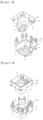
- FIGS. 5-7 illustrate an actuator and connector assembly 210 according to another embodiment of the disclosure to illustrate another example of the actuator 12 employed with an application specific connector 214 and a component 200.
- the actuator 12 of FIG. 5 is the same as the actuator 12 of FIGS. 1-4 . Therefore, the same reference numerals of FIGS. 1-4 used to describe the actuator 12 are used to describe the actuator 12 of FIGS. 5-6 .
- the connector 214 and the component 200 of FIGS. 5-6 are different from the connector 14 and the component 200 of FIGS. 1-4 .
- features of the connector 214 and the component 200 of FIGS. 5-6 similar to the features of the connector 214 and the component 200 of FIGS. 1-4 include the same reference numerals except with a leading "2," for convenience.
- the connector 214 is substantially the same as the connector 214 of FIGS. 1-4 except the connector 214 includes four of the holes 244 for receiving four of the fasteners 146 for coupling the connector 214 to the component 200. Additionally, the outer contour and shape of the connector 214 is different to adapt to the particular component 200.
- the socket 250, and the corresponding pins 252 is oriented in both a horizontal direction and a vertical direction, wherein a first portion of the socket 250 extends horizontally to horizontally engage with the electrical conductor and a second portion of the socket 250 extend vertically to extend into the actuator 12.
- An internal contour of the connector 214 defining the cavity 243 is substantially the same as the inner contour of the connector 14 of FIGS. 1-4 .
- the component 200 is a valve for a coolant circuit of the vehicle.
- the housing 260 of the component 200 includes the holes 280 for receiving the fasteners 146.
- the component 200 is configured as a multi-way valve wherein the rotational element 275 such as a cylindrical element is coupled to the shaft 20 of the internal components 18 of the actuator 12.
- the actuator and connector assembly 10, 210 of the present disclosure permits the universal actuator 12, which is otherwise incompatible with various ones of the component 100, 200, to be coupled to the component 100, 200 via the connector 14, 214.
- a separate actuator is not needed for each different application and component.
- Various actuators do not have to be manufactured to conform to the desired component, thus minimizing manufacturing costs and inefficiency.
- the same actuator 12, or multiple actuators with the same configurations can be coupled to each varying one of the components 100, 200 with the application specific connector 14, 214.
Landscapes
- Engineering & Computer Science (AREA)
- General Engineering & Computer Science (AREA)
- Mechanical Engineering (AREA)
- Power Engineering (AREA)
- Details Of Connecting Devices For Male And Female Coupling (AREA)
- Valve Housings (AREA)
- Connector Housings Or Holding Contact Members (AREA)
Applications Claiming Priority (3)
| Application Number | Priority Date | Filing Date | Title |
|---|---|---|---|
| US16/188,648 US20200153131A1 (en) | 2018-11-13 | 2018-11-13 | Adaptation of multi purpose actuator |
| EP19883786.6A EP3881399A1 (fr) | 2018-11-13 | 2019-10-31 | Adaptation d'actionneur multi-usage |
| PCT/KR2019/014539 WO2020101228A1 (fr) | 2018-11-13 | 2019-10-31 | Adaptation d'actionneur multi-usage |
Related Parent Applications (1)
| Application Number | Title | Priority Date | Filing Date |
|---|---|---|---|
| EP19883786.6A Division EP3881399A1 (fr) | 2018-11-13 | 2019-10-31 | Adaptation d'actionneur multi-usage |
Publications (1)
| Publication Number | Publication Date |
|---|---|
| EP4145643A1 true EP4145643A1 (fr) | 2023-03-08 |
Family
ID=70551863
Family Applications (2)
| Application Number | Title | Priority Date | Filing Date |
|---|---|---|---|
| EP19883786.6A Withdrawn EP3881399A1 (fr) | 2018-11-13 | 2019-10-31 | Adaptation d'actionneur multi-usage |
| EP22200267.7A Pending EP4145643A1 (fr) | 2018-11-13 | 2019-10-31 | Adaptation d'un actionneur polyvalent |
Family Applications Before (1)
| Application Number | Title | Priority Date | Filing Date |
|---|---|---|---|
| EP19883786.6A Withdrawn EP3881399A1 (fr) | 2018-11-13 | 2019-10-31 | Adaptation d'actionneur multi-usage |
Country Status (5)
| Country | Link |
|---|---|
| US (1) | US20200153131A1 (fr) |
| EP (2) | EP3881399A1 (fr) |
| KR (1) | KR102359120B1 (fr) |
| CN (1) | CN112889191A (fr) |
| WO (1) | WO2020101228A1 (fr) |
Families Citing this family (1)
| Publication number | Priority date | Publication date | Assignee | Title |
|---|---|---|---|---|
| JP2023038775A (ja) * | 2021-09-07 | 2023-03-17 | 株式会社不二工機 | 弁装置及び弁本体部 |
Citations (5)
| Publication number | Priority date | Publication date | Assignee | Title |
|---|---|---|---|---|
| WO2013095895A2 (fr) * | 2011-12-19 | 2013-06-27 | Carrier Corporation | Système d'alimentation pour système de réfrigération de transport |
| US20140260726A1 (en) * | 2013-03-15 | 2014-09-18 | Cummins Ip, Inc. | Multi-purpose actuator |
| US20160380509A1 (en) * | 2015-06-24 | 2016-12-29 | Cts Corporation | Rotary Actuator |
| US20180062479A1 (en) * | 2016-08-24 | 2018-03-01 | Cts Corporation | Modular Vehicle Engine Component Actuator |
| US20180266530A1 (en) * | 2017-03-15 | 2018-09-20 | Don Alfano | Electro-mechanical linear actuator |
Family Cites Families (7)
| Publication number | Priority date | Publication date | Assignee | Title |
|---|---|---|---|---|
| US7131635B2 (en) * | 2004-12-17 | 2006-11-07 | Invensys Building Systems, Inc. | Removable interconnection of an actuator to a valve body |
| JP4081532B2 (ja) | 2005-04-05 | 2008-04-30 | モレックス インコーポレーテッド | 中継コネクタ |
| ITTO20070044U1 (it) * | 2007-03-27 | 2008-09-28 | Elbi Int Spa | Dispositivo attuatore elettromeccanico, particolarmente per l'azionamento di valvole fluidiche |
| US8733735B2 (en) * | 2010-11-11 | 2014-05-27 | Johnson Controls Technology Company | Valve mounting adaptor |
| US8789807B2 (en) * | 2011-02-09 | 2014-07-29 | Kmc Controls, Inc. | Quick disconnect actuator mounting |
| US10508422B2 (en) * | 2015-12-22 | 2019-12-17 | Waxman Consumer Products Group Inc. | Shutoff system for water valve |
| CN106015688B (zh) * | 2016-07-11 | 2018-06-26 | 乐清市奥格节能自控系统有限公司 | 万能连接的电动执行器 |
-
2018
- 2018-11-13 US US16/188,648 patent/US20200153131A1/en not_active Abandoned
-
2019
- 2019-10-14 KR KR1020190127242A patent/KR102359120B1/ko active IP Right Grant
- 2019-10-31 WO PCT/KR2019/014539 patent/WO2020101228A1/fr unknown
- 2019-10-31 CN CN201980067719.8A patent/CN112889191A/zh active Pending
- 2019-10-31 EP EP19883786.6A patent/EP3881399A1/fr not_active Withdrawn
- 2019-10-31 EP EP22200267.7A patent/EP4145643A1/fr active Pending
Patent Citations (5)
| Publication number | Priority date | Publication date | Assignee | Title |
|---|---|---|---|---|
| WO2013095895A2 (fr) * | 2011-12-19 | 2013-06-27 | Carrier Corporation | Système d'alimentation pour système de réfrigération de transport |
| US20140260726A1 (en) * | 2013-03-15 | 2014-09-18 | Cummins Ip, Inc. | Multi-purpose actuator |
| US20160380509A1 (en) * | 2015-06-24 | 2016-12-29 | Cts Corporation | Rotary Actuator |
| US20180062479A1 (en) * | 2016-08-24 | 2018-03-01 | Cts Corporation | Modular Vehicle Engine Component Actuator |
| US20180266530A1 (en) * | 2017-03-15 | 2018-09-20 | Don Alfano | Electro-mechanical linear actuator |
Also Published As
| Publication number | Publication date |
|---|---|
| WO2020101228A1 (fr) | 2020-05-22 |
| EP3881399A1 (fr) | 2021-09-22 |
| KR20200055650A (ko) | 2020-05-21 |
| KR102359120B1 (ko) | 2022-02-08 |
| CN112889191A (zh) | 2021-06-01 |
| US20200153131A1 (en) | 2020-05-14 |
Similar Documents
| Publication | Publication Date | Title |
|---|---|---|
| US6903473B2 (en) | Motor having connector housing | |
| US9768542B2 (en) | Blind electrical connector to printed circuit board in housing | |
| US20180062479A1 (en) | Modular Vehicle Engine Component Actuator | |
| US7231847B2 (en) | Axle assembly with threaded cover pan attachment and method of assembly | |
| US20080036316A1 (en) | Geared motor | |
| US20050217010A1 (en) | Automatic open/close device for toilet seat or toilet cover | |
| KR101676561B1 (ko) | 액츄에이터 장치 | |
| US8297150B2 (en) | Gearbox | |
| KR20050111644A (ko) | 전자장치 인터페이스를 구비한 기어장치 구동 유닛 | |
| US7594452B2 (en) | Control unit mounting structure for power transmission device | |
| KR102530792B1 (ko) | 컴팩트 기어 모터 | |
| US7183682B2 (en) | Motor having speed reducer and control circuit | |
| EP4145643A1 (fr) | Adaptation d'un actionneur polyvalent | |
| JP6449463B2 (ja) | ハウジングに対するモータの一体ロックを有する小型のアクチュエータ | |
| US20140260726A1 (en) | Multi-purpose actuator | |
| US9657650B2 (en) | Electronic throttle body assembly | |
| JP5551989B2 (ja) | リニアアクチュエータ | |
| US6171125B1 (en) | Electrical connector for solenoids on vehicle transmissions | |
| ITBO990595A1 (it) | Corpo farfallato . | |
| CN106369112B (zh) | 驱动装置 | |
| JP5598021B2 (ja) | 無段変速機及びアクチュエータ | |
| US20150056907A1 (en) | Actuator, Particularly For A Heating, Ventilation And/Or Air-Conditioning Installation | |
| CN111697760B (zh) | 电子执行器 | |
| EP1213564A2 (fr) | Ensemble de capteur enfichable | |
| CN220984916U (zh) | 线束连接装置 |
Legal Events
| Date | Code | Title | Description |
|---|---|---|---|
| PUAI | Public reference made under article 153(3) epc to a published international application that has entered the european phase |
Free format text: ORIGINAL CODE: 0009012 |
|
| STAA | Information on the status of an ep patent application or granted ep patent |
Free format text: STATUS: THE APPLICATION HAS BEEN PUBLISHED |
|
| AC | Divisional application: reference to earlier application |
Ref document number: 3881399 Country of ref document: EP Kind code of ref document: P |
|
| AK | Designated contracting states |
Kind code of ref document: A1 Designated state(s): AL AT BE BG CH CY CZ DE DK EE ES FI FR GB GR HR HU IE IS IT LI LT LU LV MC MK MT NL NO PL PT RO RS SE SI SK SM TR |
|
| STAA | Information on the status of an ep patent application or granted ep patent |
Free format text: STATUS: REQUEST FOR EXAMINATION WAS MADE |
|
| 17P | Request for examination filed |
Effective date: 20230906 |
|
| RBV | Designated contracting states (corrected) |
Designated state(s): AL AT BE BG CH CY CZ DE DK EE ES FI FR GB GR HR HU IE IS IT LI LT LU LV MC MK MT NL NO PL PT RO RS SE SI SK SM TR |
|
| STAA | Information on the status of an ep patent application or granted ep patent |
Free format text: STATUS: EXAMINATION IS IN PROGRESS |
|
| 17Q | First examination report despatched |
Effective date: 20240628 |