EP4144992B1 - Schraubenverdichter mit zwischenprodukt-auslassanschluss - Google Patents
Schraubenverdichter mit zwischenprodukt-auslassanschluss Download PDFInfo
- Publication number
- EP4144992B1 EP4144992B1 EP22190656.3A EP22190656A EP4144992B1 EP 4144992 B1 EP4144992 B1 EP 4144992B1 EP 22190656 A EP22190656 A EP 22190656A EP 4144992 B1 EP4144992 B1 EP 4144992B1
- Authority
- EP
- European Patent Office
- Prior art keywords
- discharge port
- screw compressor
- intermediate discharge
- flow
- compression chamber
- Prior art date
- Legal status (The legal status is an assumption and is not a legal conclusion. Google has not performed a legal analysis and makes no representation as to the accuracy of the status listed.)
- Active
Links
Images





Classifications
-
- F—MECHANICAL ENGINEERING; LIGHTING; HEATING; WEAPONS; BLASTING
- F04—POSITIVE - DISPLACEMENT MACHINES FOR LIQUIDS; PUMPS FOR LIQUIDS OR ELASTIC FLUIDS
- F04C—ROTARY-PISTON, OR OSCILLATING-PISTON, POSITIVE-DISPLACEMENT MACHINES FOR LIQUIDS; ROTARY-PISTON, OR OSCILLATING-PISTON, POSITIVE-DISPLACEMENT PUMPS
- F04C18/00—Rotary-piston pumps specially adapted for elastic fluids
- F04C18/08—Rotary-piston pumps specially adapted for elastic fluids of intermeshing-engagement type, i.e. with engagement of co-operating members similar to that of toothed gearing
- F04C18/12—Rotary-piston pumps specially adapted for elastic fluids of intermeshing-engagement type, i.e. with engagement of co-operating members similar to that of toothed gearing of other than internal-axis type
- F04C18/14—Rotary-piston pumps specially adapted for elastic fluids of intermeshing-engagement type, i.e. with engagement of co-operating members similar to that of toothed gearing of other than internal-axis type with toothed rotary pistons
- F04C18/16—Rotary-piston pumps specially adapted for elastic fluids of intermeshing-engagement type, i.e. with engagement of co-operating members similar to that of toothed gearing of other than internal-axis type with toothed rotary pistons with helical teeth, e.g. chevron-shaped, screw type
-
- F—MECHANICAL ENGINEERING; LIGHTING; HEATING; WEAPONS; BLASTING
- F04—POSITIVE - DISPLACEMENT MACHINES FOR LIQUIDS; PUMPS FOR LIQUIDS OR ELASTIC FLUIDS
- F04C—ROTARY-PISTON, OR OSCILLATING-PISTON, POSITIVE-DISPLACEMENT MACHINES FOR LIQUIDS; ROTARY-PISTON, OR OSCILLATING-PISTON, POSITIVE-DISPLACEMENT PUMPS
- F04C27/00—Sealing arrangements in rotary-piston pumps specially adapted for elastic fluids
-
- F—MECHANICAL ENGINEERING; LIGHTING; HEATING; WEAPONS; BLASTING
- F04—POSITIVE - DISPLACEMENT MACHINES FOR LIQUIDS; PUMPS FOR LIQUIDS OR ELASTIC FLUIDS
- F04C—ROTARY-PISTON, OR OSCILLATING-PISTON, POSITIVE-DISPLACEMENT MACHINES FOR LIQUIDS; ROTARY-PISTON, OR OSCILLATING-PISTON, POSITIVE-DISPLACEMENT PUMPS
- F04C28/00—Control of, monitoring of, or safety arrangements for, pumps or pumping installations specially adapted for elastic fluids
- F04C28/24—Control of, monitoring of, or safety arrangements for, pumps or pumping installations specially adapted for elastic fluids characterised by using valves controlling pressure or flow rate, e.g. discharge valves or unloading valves
-
- F—MECHANICAL ENGINEERING; LIGHTING; HEATING; WEAPONS; BLASTING
- F04—POSITIVE - DISPLACEMENT MACHINES FOR LIQUIDS; PUMPS FOR LIQUIDS OR ELASTIC FLUIDS
- F04C—ROTARY-PISTON, OR OSCILLATING-PISTON, POSITIVE-DISPLACEMENT MACHINES FOR LIQUIDS; ROTARY-PISTON, OR OSCILLATING-PISTON, POSITIVE-DISPLACEMENT PUMPS
- F04C29/00—Component parts, details or accessories of pumps or pumping installations, not provided for in groups F04C18/00 - F04C28/00
- F04C29/12—Arrangements for admission or discharge of the working fluid, e.g. constructional features of the inlet or outlet
-
- F—MECHANICAL ENGINEERING; LIGHTING; HEATING; WEAPONS; BLASTING
- F25—REFRIGERATION OR COOLING; COMBINED HEATING AND REFRIGERATION SYSTEMS; HEAT PUMP SYSTEMS; MANUFACTURE OR STORAGE OF ICE; LIQUEFACTION SOLIDIFICATION OF GASES
- F25B—REFRIGERATION MACHINES, PLANTS OR SYSTEMS; COMBINED HEATING AND REFRIGERATION SYSTEMS; HEAT PUMP SYSTEMS
- F25B1/00—Compression machines, plants or systems with non-reversible cycle
- F25B1/04—Compression machines, plants or systems with non-reversible cycle with compressor of rotary type
- F25B1/047—Compression machines, plants or systems with non-reversible cycle with compressor of rotary type of screw type
-
- F—MECHANICAL ENGINEERING; LIGHTING; HEATING; WEAPONS; BLASTING
- F25—REFRIGERATION OR COOLING; COMBINED HEATING AND REFRIGERATION SYSTEMS; HEAT PUMP SYSTEMS; MANUFACTURE OR STORAGE OF ICE; LIQUEFACTION SOLIDIFICATION OF GASES
- F25B—REFRIGERATION MACHINES, PLANTS OR SYSTEMS; COMBINED HEATING AND REFRIGERATION SYSTEMS; HEAT PUMP SYSTEMS
- F25B49/00—Arrangement or mounting of control or safety devices
- F25B49/02—Arrangement or mounting of control or safety devices for compression type machines, plants or systems
- F25B49/022—Compressor control arrangements
-
- F—MECHANICAL ENGINEERING; LIGHTING; HEATING; WEAPONS; BLASTING
- F04—POSITIVE - DISPLACEMENT MACHINES FOR LIQUIDS; PUMPS FOR LIQUIDS OR ELASTIC FLUIDS
- F04C—ROTARY-PISTON, OR OSCILLATING-PISTON, POSITIVE-DISPLACEMENT MACHINES FOR LIQUIDS; ROTARY-PISTON, OR OSCILLATING-PISTON, POSITIVE-DISPLACEMENT PUMPS
- F04C28/00—Control of, monitoring of, or safety arrangements for, pumps or pumping installations specially adapted for elastic fluids
- F04C28/10—Control of, monitoring of, or safety arrangements for, pumps or pumping installations specially adapted for elastic fluids characterised by changing the positions of the inlet or outlet openings with respect to the working chamber
-
- F—MECHANICAL ENGINEERING; LIGHTING; HEATING; WEAPONS; BLASTING
- F25—REFRIGERATION OR COOLING; COMBINED HEATING AND REFRIGERATION SYSTEMS; HEAT PUMP SYSTEMS; MANUFACTURE OR STORAGE OF ICE; LIQUEFACTION SOLIDIFICATION OF GASES
- F25B—REFRIGERATION MACHINES, PLANTS OR SYSTEMS; COMBINED HEATING AND REFRIGERATION SYSTEMS; HEAT PUMP SYSTEMS
- F25B2600/00—Control issues
- F25B2600/02—Compressor control
- F25B2600/026—Compressor control by controlling unloaders
- F25B2600/0262—Compressor control by controlling unloaders internal to the compressor
-
- F—MECHANICAL ENGINEERING; LIGHTING; HEATING; WEAPONS; BLASTING
- F25—REFRIGERATION OR COOLING; COMBINED HEATING AND REFRIGERATION SYSTEMS; HEAT PUMP SYSTEMS; MANUFACTURE OR STORAGE OF ICE; LIQUEFACTION SOLIDIFICATION OF GASES
- F25B—REFRIGERATION MACHINES, PLANTS OR SYSTEMS; COMBINED HEATING AND REFRIGERATION SYSTEMS; HEAT PUMP SYSTEMS
- F25B2600/00—Control issues
- F25B2600/02—Compressor control
- F25B2600/027—Compressor control by controlling pressure
Definitions
- This disclosure relates generally to fluid discharge in a vapor compression system. More specifically, this disclosure relates to an intermediate discharge port of a compressor in a vapor compression system such as, but not limited to, a heating, ventilation, and air conditioning (HVAC) system.
- HVAC heating, ventilation, and air conditioning
- a screw compressor generally includes one or more rotors (e.g., one or more rotary screws).
- a screw compressor includes a pair of rotors (e.g., two rotary screws) which rotate relative to each other to compress a working fluid such as, but not limited to, a refrigerant or the like.
- US 2013/216414 A1 describes a system and method for controlling the volume ratio of a compressor.
- WO 2015/094466 A1 describes a compressor including a housing having a suction inlet and a discharge outlet.
- EP 0 350 426 A2 describes a compressor having a movable trapped volume such as a screw or scroll type of compressor.
- DE 12 17 542 B describes a device for controlling a screw rotor machine for compression or expansion of gaseous media with at least two intermeshing ridges and grooves of male and female screw rotors in a working space.
- GB 384 355 A describes a rotary pump comprising a number of intermeshing screws.
- This disclosure relates generally to fluid discharge in a vapor compression system. More specifically, this disclosure relates to an intermediate discharge port of a compressor in a vapor compression system such as, but not limited to, a heating, ventilation, and air conditioning (HVAC) system.
- HVAC heating, ventilation, and air conditioning
- the compressor is a screw compressor.
- the screw compressor can be used in an HVAC system (sometimes referred to alternatively as a refrigeration system) to compress a heat transfer fluid.
- the heat transfer fluid can be, for example, a refrigerant.
- the intermediate discharge port for the screw compressor can be included when the screw compressor is manufactured. In an embodiment, the intermediate discharge port for the screw compressor can be retrofit into the screw compressor that was manufactured without the intermediate discharge port. In an embodiment, the intermediate discharge port for the screw compressor can be retrofit into the screw compressor even after the screw compressor has been operated.
- the intermediate discharge port can be added to the screw compressor at a location that is in fluid communication with a compression chamber of the screw compressor. In an embodiment, the intermediate discharge port can be added to the screw compressor at a location that is disposed in fluid communication with a compression chamber of the screw compressor and is at a location between the inlet port and the outlet port of the compressor.
- a fluid flow state (e.g., flow-permitted, flow-blocked) of the intermediate discharge port of the screw compressor is controlled based on a pressure differential.
- the fluid flow state of the intermediate discharge port is controlled by a biasing mechanism actuated in response to a signal from a controller.
- the screw compressor includes a compressor housing defining a working chamber, the housing including a plurality of bores; a first rotor having helical threads, the first rotor being housed in a first of the plurality of bores; a second rotor having helical threads intermeshing with the helical threads of the first rotor, the second rotor being housed in a second of the plurality of bores; an inlet port that receives a fluid to be compressed; an outlet port that receives a compressed fluid; and an intermediate discharge port disposed between the compression chamber and the outlet port, the intermediate discharge port including a sealing member and a biasing mechanism, fluid flow being prevented between the compression chamber and the intermediate discharge port when in a flow-blocked state, and fluid flow being enabled from the compression chamber through the intermediate discharge port when in a flow-permitted state.
- the HVAC system includes a condenser, an expansion device, and an evaporator, and a screw compressor fluidly connected and forming a heat transfer circuit.
- the screw compressor includes a compressor housing defining a working chamber, the housing including two bores; a first rotor having helical threads, the first rotor being housed in a first of the two bores; a second rotor having helical threads intermeshing with the helical threads of the first rotor, the second rotor being housed in a second of the two bores; a suction port that receives a fluid to be compressed; an outlet port that receives a compressed fluid; and an intermediate discharge port disposed between the compression chamber and the outlet port, the intermediate discharge port including a sealing member and a biasing mechanism, fluid flow being prevented between the compression chamber and the intermediate discharge port when in a flow-blocked state, and fluid flow being enabled from the compression chamber through the intermediate discharge port when in a flow-permitted state.
- the method includes providing an intermediate discharge port at a location in fluid communication with a compression chamber of a screw compressor, the intermediate discharge port being disposed between an inlet port and an outlet port of the screw compressor, wherein when operating the screw compressor at part-load, discharging a portion of a working fluid being compressed from the compression chamber toward a discharge of the screw compressor, the working fluid being at a pressure that is lower than a discharge pressure of the screw compressor, and when operating the screw compressor at full-load, discharging the working fluid being compressed from the outlet port of the screw compressor.
- This disclosure relates generally to fluid discharge in a vapor compression system. More specifically, this disclosure relates to an intermediate discharge port of a compressor in a vapor compression system such as, but not limited to, a heating, ventilation, and air conditioning (HVAC) system.
- HVAC heating, ventilation, and air conditioning
- the compressor may over pressurize the working fluid.
- an intermediate discharge port can be added to the compressor to allow the working fluid to leave the compression chamber prior to reaching the discharge port.
- the intermediate discharge port can increase an efficiency of the compressor by reducing the over pressurization of the working fluid.
- an increase in efficiency can be at or about 12%.
- an increase in efficiency can be up to 12% or up to about 12%.
- the intermediate discharge port is not determinative of a capacity of the screw compressor. Further, slide valves generally move in a direction that is parallel to the rotors of the screw compressor, while the intermediate discharge port generally moves in a direction that is about perpendicular to the rotors of the screw compressor.
- FIG. 1 is a schematic diagram of a heat transfer circuit 10, according to an embodiment.
- the heat transfer circuit 10 generally includes a compressor 12, a condenser 14, an expansion device 16, and an evaporator 18.
- the compressor 12 can be powered by an electric motor (not shown).
- the heat transfer circuit 10 is an example and can be modified to include additional components.
- the heat transfer circuit 10 can include an economizer heat exchanger, one or more flow control devices, a receiver tank, a dryer, a suction-liquid heat exchanger, or the like.
- the heat transfer circuit 10 can generally be applied in a variety of systems (e.g., vapor compression systems) used to control an environmental condition (e.g., temperature, humidity, air quality, or the like) in a space (generally referred to as a conditioned space).
- systems e.g., vapor compression systems
- an environmental condition e.g., temperature, humidity, air quality, or the like
- a space generally referred to as a conditioned space.
- systems include, but are not limited to HVAC systems, transport refrigeration systems, or the like.
- the components of the heat transfer circuit 10 are fluidly connected.
- the heat transfer circuit 10 can be specifically configured to be a cooling system (e.g., a fluid chiller of an HVAC system and/or an air conditioning system) capable of operating in a cooling mode.
- the heat transfer circuit 10 can be specifically configured to be a heat pump system which can operate in both a cooling mode and a heating/defrost mode.
- Heat transfer circuit 10 operates according to generally known principles.
- the heat transfer circuit 10 can be configured to heat or cool a process fluid.
- the process fluid can be, for example, a fluid such as, but not limited to, water or the like, in which case the heat transfer circuit 10 may be generally representative of a chiller system.
- the process fluid can be, for example, a fluid such as, but not limited to, air or the like, in which case the heat transfer circuit 10 may be generally representative of an air conditioner or heat pump.
- the compressor 12 is generally representative of a screw compressor.
- the compressor 12 compresses a working fluid (e.g., a heat transfer fluid such as refrigerant or the like) from a relatively lower pressure gas to a relatively higher-pressure gas.
- the relatively higher-pressure and higher temperature gas is discharged from the compressor 12 and flows through the condenser 14.
- the working fluid flows through the condenser 14 and rejects heat to the process fluid (e.g., a heat transfer fluid or medium such as, but not limited to, water, air, etc.), thereby cooling the working fluid.
- the cooled working fluid which is now in a liquid form, flows to the expansion device 16.
- the expansion device 16 reduces the pressure of the working fluid.
- the working fluid which is now in a mixed liquid and gaseous form flows to the evaporator 18.
- the working fluid flows through the evaporator 18 and absorbs heat from the process fluid (e.g., a heat transfer fluid or medium such as, but not limited to, water, air, etc.), heating the working fluid, and converting it to a gaseous form.
- the gaseous working fluid then returns to the compressor 12.
- the above-described process continues while the heat transfer circuit is operating, for example, in a cooling mode (e.g., while the compressor 12 is enabled).
- the compressor 12 can be controlled by, for example, a controller 20.
- the controller 20 can, in an embodiment, control one or more of the other components of the heat transfer circuit 10 or the HVAC system corresponding to the heat transfer circuit 10.
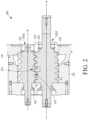
- FIG 2 illustrates a screw compressor 100 with which embodiments as disclosed in this specification can be practiced, according to an embodiment.
- the screw compressor 100 can be used in the heat transfer circuit 10 of Figure 1 (e.g., as the compressor 12). It is to be appreciated that the screw compressor 100 can be used for purposes other than in the heat transfer circuit 10.
- the screw compressor 100 can be used to compress air or gases other than a heat transfer fluid (e.g., natural gas, etc.).
- the screw compressor 100 includes additional features that are not described in detail in this specification.
- the screw compressor 100 can include a lubricant sump for storing lubricant to be introduced to the moving features of the screw compressor 100.
- the screw compressor 100 includes a first helical rotor 105 and a second helical rotor 110 disposed in a rotor housing 115.
- the rotor housing 115 includes a plurality of bores 120A and 120B.
- the plurality of bores 120A and 120B are configured to accept the first helical rotor 105 and the second helical rotor 110.
- the first helical rotor 105 has a plurality of spiral lobes 125.
- the plurality of spiral lobes 125 of the first helical rotor 105 can be received by a plurality of spiral grooves 130 of the second helical rotor 110, generally referred to as the female rotor.
- the spiral lobes 125 and the spiral grooves 130 can alternatively be referred to as the threads 125, 130.
- the first helical rotor 105 and the second helical rotor 110 are arranged within the housing 115 such that the spiral grooves 130 intermesh with the spiral lobes 125 of the first helical rotor 105.
- the first and second helical rotors 105, 110 rotate counter to each other. That is, the first helical rotor 105 rotates about an axis A in a first direction while the second helical rotor 110 rotates about an axis B in a second direction that is opposite the first direction.
- the screw compressor 100 includes an inlet port 135 and an outlet port 140.
- the rotating first and second helical rotors 105, 110 can receive a working fluid (e.g., heat transfer fluid such as refrigerant or the like) at the inlet port 135.
- the working fluid can be compressed between the spiral lobes 125 and the spiral grooves 130 (in a pocket 145 formed therebetween) and discharged at the outlet port 140.
- the pocket is generally referred to as the compression chamber 145 and is defined between the spiral lobes 125 and the spiral grooves 130 and an interior surface of the housing 115.
- the compression chamber 145 may move from the inlet port 135 to the outlet port 140 when the first and second helical rotors 105, 110 rotate.
- the compression chamber 145 may continuously reduce in volume while moving from the inlet port 135 to the discharge port 145. This continuous reduction in volume can compress the working fluid (e.g., heat transfer fluid such as refrigerant or the like) in the compression chamber 145.
- working fluid e.g., heat transfer fluid such as refrigerant or the like
- the screw compressor 100 can include an intermediate discharge port 175.
- the intermediate discharge port 175 can, for example, provide an exit flow path for the working fluid being compressed (e.g., heat transfer fluid such as refrigerant or the like).
- the intermediate discharge port 175 may alternatively be referred to as the radial discharge port 175, the radial intermediate discharge port 175, or the like.
- the intermediate discharge port 175 can, for example, enable the fluid being compressed to radially exit the compression chamber 145 prior to being discharged from the axial outlet port 140.
- the intermediate discharge port 175 can be oriented such that the fluid being compressed exits in a direction that is about perpendicular to the axial direction that is defined by the axis A of the first helical rotor 105 and the axis B of the second axial rotor 110.
- the intermediate discharge port 175 can prevent overcompression of the working fluid by radially discharging the fluid from the compression chamber 145 prior to the outlet port 140. In an embodiment, preventing overcompression of the fluid can increase an efficiency of the screw compressor 100. In an embodiment, an increase in efficiency of the screw compressor 100 can be at or about 12%. In an embodiment, an increase in efficiency of the screw compressor 100 can be up to 12% or up to about 12%.
- the intermediate discharge port 175 is shown and described in additional detail according to various embodiments in accordance with Figures 3 - 6 below.
- the intermediate discharge port 175 can be included in the screw compressor 100 at a time of manufacturing. In an embodiment, the intermediate discharge port 175 can be retrofitted into the screw compressor 100 after manufacturing. In an embodiment, the intermediate discharge port 175 can be retrofitted into the screw compressor 100 even after the screw compressor 100 has been in use.
- Figure 3 illustrates the screw compressor 100 including an intermediate discharge port 175A, according to an embodiment.
- the intermediate discharge port 175A is in a flow-blocked (e.g., closed) state.
- Figure 4 illustrates the screw compressor 100 including the intermediate discharge port 175A, according to an embodiment.
- the intermediate discharge port 175A is in a flow-permitted (e.g., opened) state.
- Figures 3 - 4 will be described generally, unless specific reference is made to the contrary.
- the screw compressor 100 can include a plurality of intermediate discharge ports 175A.
- the screw compressor 100 can include a first intermediate discharge port at a first intermediate location and a second intermediate discharge port at a second intermediate location, with the first and second intermediate locations being selected to provide an intermediate discharge at a particular compressor load.
- the intermediate discharge port 175A includes a biasing mechanism 180; a sealing member 185 connected to the biasing mechanism 180 and disposed within a chamber 190 of the intermediate discharge port 175A; and a plurality of apertures 195.
- the biasing mechanism 180 can be an actively controlled mechanism.
- the biasing mechanism 180 can be a biasing mechanism electrically connected to a controller (e.g., the controller 20 in Figure 1 ).
- the controller can be connected to a sensor (e.g., a pressure sensor, etc.).
- the controller can provide an electric signal to the biasing mechanism 180 to control whether the biasing mechanism 180 is in the flow-blocked state ( Figure 3 ) or in the flow-permitted state ( Figure 4 ).
- the controller might identify that the screw compressor 100 is operating at full capacity, in which case the controller might send a signal to the biasing mechanism 180 to place / maintain the biasing mechanism 180 in the flow-blocked state of Figure 3 .
- the controller might identify that the screw compressor 100 is operating at a capacity less than full capacity, in which case the controller might send a signal to the biasing mechanism 180 to place / maintain the biasing mechanism 180 in the flow-permitted state of Figure 4 .
- the biasing mechanism 180 is a passively controlled mechanism.
- the biasing mechanism 180 is a biasing mechanism that is controllable between the flow-blocked ( Figure 3 ) and the flow-permitted ( Figure 4 ) states based on a pressure differential between the compression chamber 145 and the discharge.
- the intermediate discharge port 175A alternates between the flow-blocked state ( Figure 3 ) and the flow-permitted state ( Figure 4 ) based on pressure differential of the discharge and the compression chamber 145.
- the intermediate discharge port 175A may be disposed at a top portion of the housing 115 such that the biasing mechanism moves vertically upward (e.g.
- a passively controlled biasing mechanism may be placed in a different orientation, according to an embodiment, but for simplicity of the design, the vertical orientation may be preferred.
- the intermediate discharge port 175A can move radially (e.g., about perpendicular to the rotors 105, 110) from or toward the compression chamber 145.
- the intermediate discharge port 175A can be in the flow-permitted state ( Figure 4 ).
- the pressure of the discharge is lower than the pressure in the compression chamber 145.
- the pressurized fluid can force the sealing member 185 in the d1 direction (vertically upward), enabling flow of the working fluid from the compression chamber 145 through the intermediate discharge port 175A.
- the pressure of the working fluid at the discharge may be higher than the pressure of the working fluid in the compression chamber 145.
- the sealing member 185 may be forced in the d2 direction (vertically downward), thereby causing the sealing member 185 to be in sealing contact with the surface 190A, thereby preventing flow through the intermediate discharge port 175A.
- the fluid being compressed can be discharged through the outlet port 140.
- the biasing mechanism 180 is connected to the sealing member 185 such that the biasing mechanism 180 can move the sealing member 185 in either a direction d1 (vertically up with respect to the page in the figures) or a direction d2 (vertically down with respect to the page in the figures).
- the sealing member 185 can include a surface 185A which can serve as a sealing surface in a flow-blocked state. That is, the surface 185A can form a sealing engagement with a sealing surface 190A of the chamber 190 when in the flow-blocked state ( Figure 3 ). In the flow-blocked state ( Figure 3 ), the surface 185A of the sealing member 185 can prevent a fluid (e.g., working fluid such as a heat transfer fluid, etc.) from radially exiting the compression chamber 145.
- a fluid e.g., working fluid such as a heat transfer fluid, etc.
- the chamber 190 can be sized to permit the sealing member 185 to translate in the d1 and d2 directions.
- the chamber 190 can be in fluid communication with a discharge of the screw compressor 100 when the intermediate discharge port 175A is in the flow-permitted state ( Figure 4 ).
- the plurality of apertures 195 is disposed within the housing 115. In an embodiment, the plurality of apertures 195 is bored into the housing 115.
- the plurality of apertures 195 is fluidly connected with the chamber 190, and accordingly with the discharge of the screw compressor 100.
- the plurality of apertures 195 is fluidly sealed from the chamber 190 by a sealing engagement between the surface 185A of the sealing member 185 and the sealing surface 190A of the chamber 190.
- the intermediate discharge port 175A can include more than three apertures 195, according to an embodiment, or fewer than three apertures 195, according to an embodiment.
- the intermediate discharge port 175A can include four apertures 195, with two apertures being disposed in each bore 120A, 120B of the screw compressor 100 such that symmetry is maintained between each of the bores 120A, 120B.
- the apertures 195 can be based on a size of the bore 120A, 120B. Generally, a number of apertures 195 may be limited based on, for example, manufacturing limitations.
- the size and geometry of the plurality of apertures 195 can be determined based on, for example, simplicity of manufacturing, flow rate of the working fluid, or the like.
- a distance L1 from an inlet of the plurality of apertures 195 to an outlet of the plurality of apertures into the chamber 190 can be determined by, for example, manufacturing tolerances or the like. Additionally, the distance L1 can be selected to minimize an amount of the working fluid which may enter the plurality of apertures 195 when the intermediate discharge port 175 is in the flow-blocked state ( Figure 3 ).
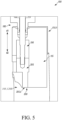
- Figure 5 illustrates the screw compressor 100 including an intermediate discharge port 175B, according to an embodiment.
- the intermediate discharge port 175B is in the flow-blocked state.
- Figure 6 illustrates the screw compressor 100 including the intermediate discharge port 175B of Figure 5 , according to an embodiment.
- the intermediate discharge port 175B is in the flow-permitted state.
- Figure 7 illustrates an alternative view of the screw compressor 100 including the intermediate discharge port 175B of Figure 5 in the flow-blocked state.
- Figures 5 - 7 will be described generally, unless specific reference is made to the contrary.
- the intermediate discharge port 175B includes a single aperture 200, according to an embodiment.
- the single aperture 200 functions similarly to the plurality of apertures 195 in the embodiment shown and described above with respect to Figures 3 - 4 .
- the aperture 200 can follow a contour of the bores 120A and 120B of the housing 115 (see Figure 7 ). A portion of the aperture 200 is in the bore 120A and another portion of the aperture 200 is in the second bore 120B. Accordingly, the aperture 200 can be approximately shaped to match a rotor-helix angle of the screw compressor 100. In an embodiment, the aperture 200 can be approximately v-shaped.
- a sealing member 205 is configured to include a surface 205A which follows a contour of the bores 120A, 120B as well ( Figure 7 ). Accordingly, the sealing member 205 can be approximately v-shaped to correspond to the aperture 200, according to an embodiment.
- the surface 205A approximately follows the contour of the bores 120A, 120B of the housing 115. Accordingly, when the intermediate discharge port 175B is in the flow-blocked state ( Figure 5 ), the bores 120A, 120B and the housing 115 may be substantially smooth.
- the intermediate discharge port 175B and corresponding shape can, for example, prevent portions of the working fluid being compressed from entering the aperture 200 when in the flow-blocked state ( Figure 5 ).
- the embodiment in Figures 5 - 6 does not include (or reduces) an area in which the working fluid being compressed can be directed when in the flow-blocked state.
- the intermediate discharge port 175B is in the flow-permitted state ( Figure 6 )
- the compression chamber 145, the aperture 200, and the discharge are fluidly connected such that the working fluid can be discharged from the intermediate discharge port 175B.
Landscapes
- Engineering & Computer Science (AREA)
- Mechanical Engineering (AREA)
- General Engineering & Computer Science (AREA)
- Physics & Mathematics (AREA)
- Thermal Sciences (AREA)
- Fluid Mechanics (AREA)
- Applications Or Details Of Rotary Compressors (AREA)
Claims (9)
- Schraubenverdichter (100), der Folgendes umfasst:ein Verdichtergehäuse (115), das eine Arbeitskammer definiert, wobei das Gehäuse mehrere Bohrungen (120A, 120B) umfasst;einen ersten Rotor (105) mit Schraubengewinden, wobei der erste Rotor in einer ersten der mehreren Bohrungen (120A, 120B) eingehaust ist;einen zweiten Rotor (110) mit Schraubengewinden, die mit den Schraubengewinden des ersten Rotors ineinandergreifen, wobei der zweite Rotor in einer zweiten der mehreren Bohrungen (120A, 120B) eingehaust ist;eine Einlasssaugöffnung (135), die ein zu verdichtendes Fluid aufnimmt;eine Auslassablassöffnung (140), die ein verdichtetes Fluid aufnimmt;eine Verdichtungskammer (145), die durch das Ineinandergreifen der Schraubengewinde des ersten Rotors (105) und der Schraubengewinde des zweiten Rotors (110) zwischen der Einlasssaugöffnung (135) und der Auslassablassöffnung (140) gebildet wird; undeinen Mitteldruckauslass (175), der fluidisch mit der Verdichtungskammer (145) verbindbar ist und zwischen der Einlasssaugöffnung (135) und der Auslassablassöffnung (140) angeordnet ist, um zu ermöglichen, dass ein Arbeitsfluid die Verdichtungskammer verlässt, bevor es die Auslassablassöffnung erreicht, wobei der Schraubenverdichter dadurch gekennzeichnet ist, dassder Mitteldruckauslass (175) an einem Abschnitt des Verdichtergehäuses (115) angeordnet ist, so dass ein Vorspannmechanismus (180), der im Mitteldruckauslass enthalten ist, basierend auf einer Druckdifferenz zwischen der Verdichtungskammer (145) und einem Auslass des Schraubenverdichters (100) an der Auslassablassöffnung (140) passiv gesteuert wird, um den Mitteldruckauslass gezielt zwischen einem Strömung blockierenden Zustand und einem Strömung gestattenden Zustand übergehen zu lassen,wobei der Mitteldruckauslass (175) ein Dichtungselement (185) mit einer Dichtungsfläche (185A) beinhaltet und einen Dichtungseingriff mit einer Fläche innerhalb des Mitteldruckauslasses bildet, wenn er durch den Vorspannmechanismus (180) so vorgespannt wird, dass er sich in dem Strömung blockierenden Zustand befindet, so dass im Strömung blockierenden Zustand ein Fluidstrom zwischen der Verdichtungskammer und dem Mitteldruckauslass verhindert wird, und wobei ein Fluidstrom von der Verdichtungskammer durch den Mitteldruckauslass ermöglicht wird, wenn er durch den Vorspannmechanismus so vorgespannt wird, dass er sich in dem Strömung gestattenden Zustand befindet, in dem die Dichtungsfläche von dem Dichtungseingriff mit der Oberfläche innerhalb des Mitteldruckauslasses gelöst ist.
- Schraubenverdichter nach Anspruch 1, wobei der Mitteldruckauslass (175) an einer Stelle der Verdichtungskammer (145) angeordnet ist, an der ein Fluid, das verdichtet wird, teilweise verdichtet wird.
- Schraubenverdichter nach Anspruch 1, wobei der Schraubenverdichter (100) mehrere Mitteldruckauslässe (175) beinhaltet, die zwischen der Einlasssaugöffnung und der Auslassablassöffnung angeordnet sind, wobei die mehreren Mitteldruckauslässe (175) an verschiedenen Stellen entlang der Verdichtungskammer zwischen der Einlasssaugöffnung und der Auslassablassöffnung angeordnet sind.
- Schraubenverdichter nach Anspruch 1, wobei das Verdichtergehäuse (115) eine oder mehrere Öffnungen (195) beinhaltet, die dazu ausgelegt sind, im Strömung gestattenden Zustand die Verdichtungskammer (145) und den Mitteldruckauslass (175) fluidisch zu verbinden.
- Schraubenverdichter nach Anspruch 4, wobei eine einzelne der Öffnungen (200) in einer Wand des Gehäuses (115) gebildet ist, wobei ein Teil der einzelnen Öffnung (200) in der ersten der mehreren Bohrungen (120) befindlich ist und ein anderer Teil der einzelnen Öffnung in der zweiten der mehreren Bohrungen befindlich ist.
- Heizungs-, Lüftungs- und Klimaanlagensystem (HLK) mit dem Schraubenverdichter nach einem der vorhergehenden Ansprüche, wobei das System Folgendes umfasst:
einen Kondensator (14) und eine Ausdehnungsvorrichtung (16), einen Verdampfer (18) und den Schraubenverdichter, fluidisch verbunden und einen Wärmeübertragungskreis bildend. - Heizungs-, Lüftungs- und Klimaanlagensystem (HLK), das Folgendes umfasst:
einen Kondensator (14), eine Ausdehnungsvorrichtung (16) und einen Verdampfer (18) und einen Schraubenverdichter (100) nach einem der Ansprüche 1-5, wobei der Schraubenverdichter fluidisch verbunden ist und einen Wärmeübertragungskreis (10) bildet. - HLK-System nach Anspruch 7, wobei der Mitteldruckauslass (175) im Strömung blockierenden Zustand ist, wenn der Schraubenverdichter (100) bei Volllast arbeitet, und im Strömung gestattenden Zustand ist, wenn der Schraubenverdichter (100) bei Teillast arbeitet.
- Verfahren, das Folgendes umfasst:Bereitstellen eines Mitteldruckauslasses (175) an einem Ort in Fluidverbindung mit einer Verdichtungskammer (145) eines Schraubenverdichters (100) durch Nachrüsten des Mitteldruckauslasses in den Schraubenverdichter nach der Herstellung, wobei der Mitteldruckauslass (175) zwischen einer Einlasssaugöffnung (135) und einer Auslassablassöffnung (140) des Schraubenverdichters angeordnet ist, um zu ermöglichen, dass ein Arbeitsfluid die Verdichtungskammer verlässt, bevor es die Auslassablassöffnung erreicht, wobei das Verfahren dadurch gekennzeichnet ist, dass der Mitteldruckauslass (175) an einem Abschnitt eines Verdichtergehäuses (115) des Schraubenverdichters angeordnet ist, so dass ein Vorspannmechanismus (180), der im Mitteldruckauslass (175) enthalten ist, basierend auf einer Druckdifferenz zwischen der Verdichtungskammer (145) und einem Auslass des Schraubenverdichters (100) an der Auslassablassöffnung (140) passiv gesteuert wird, um den Mitteldruckauslass gezielt zwischen einem Strömung blockierenden Zustand und einem Strömung gestattenden Zustand übergehen zu lassen,wobei, bei Betreiben des Schraubenverdichters mit Teillast,Ablassen eines Teils eines Arbeitsfluids, das von der Verdichtungskammer (145) verdichtet wird, in Richtung eines Ablasses des Schraubenverdichters (100), wobei das Arbeitsfluid einen Druck aufweist, der niedriger als ein Ablassdruck des Schraubenverdichters ist, undbei Betreiben des Schraubenverdichters mit Volllast,Ablassen des Arbeitsfluids, das verdichtet wird, aus der Auslassablassöffnung des Schraubenverdichters.
Applications Claiming Priority (2)
| Application Number | Priority Date | Filing Date | Title |
|---|---|---|---|
| US201662343938P | 2016-06-01 | 2016-06-01 | |
| EP17173981.6A EP3252309B1 (de) | 2016-06-01 | 2017-06-01 | Mitteldruckauslass für verdichter |
Related Parent Applications (1)
| Application Number | Title | Priority Date | Filing Date |
|---|---|---|---|
| EP17173981.6A Division EP3252309B1 (de) | 2016-06-01 | 2017-06-01 | Mitteldruckauslass für verdichter |
Publications (2)
| Publication Number | Publication Date |
|---|---|
| EP4144992A1 EP4144992A1 (de) | 2023-03-08 |
| EP4144992B1 true EP4144992B1 (de) | 2025-02-12 |
Family
ID=59021333
Family Applications (2)
| Application Number | Title | Priority Date | Filing Date |
|---|---|---|---|
| EP22190656.3A Active EP4144992B1 (de) | 2016-06-01 | 2017-06-01 | Schraubenverdichter mit zwischenprodukt-auslassanschluss |
| EP17173981.6A Active EP3252309B1 (de) | 2016-06-01 | 2017-06-01 | Mitteldruckauslass für verdichter |
Family Applications After (1)
| Application Number | Title | Priority Date | Filing Date |
|---|---|---|---|
| EP17173981.6A Active EP3252309B1 (de) | 2016-06-01 | 2017-06-01 | Mitteldruckauslass für verdichter |
Country Status (3)
| Country | Link |
|---|---|
| US (1) | US11022122B2 (de) |
| EP (2) | EP4144992B1 (de) |
| CN (1) | CN107448385B (de) |
Family Cites Families (19)
| Publication number | Priority date | Publication date | Assignee | Title |
|---|---|---|---|---|
| GB384355A (en) | 1931-08-05 | 1932-12-08 | Frederick Charles Greenfield | Improvements in and relating to rotary machines for the compression and propulsion of |
| DE1217542B (de) | 1959-06-04 | 1966-05-26 | Svenska Rotor Maskiner Ab | Einrichtung zum Regeln einer Schraubenrotormaschine |
| SE382851B (sv) * | 1974-06-24 | 1976-02-16 | Atlas Copco Ab | Forfarande for drenering av olja fran vexelladan vid en oljeinsprutad rotorkompressor samt anordning for genomforande av forfarandet |
| SE432465B (sv) * | 1980-06-02 | 1984-04-02 | Sullair Tech Ab | Ventilarrangemang for kapacitetsreglering av skruvkompressorer |
| US4388048A (en) * | 1981-03-10 | 1983-06-14 | Dunham Bush, Inc. | Stepping type unloading system for helical screw rotary compressor |
| US4878818A (en) | 1988-07-05 | 1989-11-07 | Carrier Corporation | Common compression zone access ports for positive displacement compressor |
| US5556271A (en) * | 1994-11-23 | 1996-09-17 | Coltec Industries Inc. | Valve system for capacity control of a screw compressor and method of manufacturing such valves |
| JPH08338386A (ja) * | 1995-06-14 | 1996-12-24 | Ishikawajima Harima Heavy Ind Co Ltd | スクリュー圧縮機 |
| US6135744A (en) * | 1998-04-28 | 2000-10-24 | American Standard Inc. | Piston unloader arrangement for screw compressors |
| SE510385C2 (sv) * | 1998-09-29 | 1999-05-17 | Svenska Rotor Maskiner Ab | Skruvrotorkompressor med variabel kapacitet, vilken kompressor innefattar minst en lyftventil i anslutning till en första kompressionskammare |
| JP3673743B2 (ja) * | 2001-09-27 | 2005-07-20 | 大晃機械工業株式会社 | スクリュー式真空ポンプ |
| CN102414448B (zh) * | 2009-03-26 | 2015-04-15 | 江森自控科技公司 | 压缩机 |
| DE102009016790A1 (de) * | 2009-04-07 | 2010-10-14 | Mosemann, Dieter, Dr. | Schraubenverdichteraggregat mit Volumenstromregelung |
| KR101484130B1 (ko) | 2010-09-14 | 2015-01-19 | 존슨 컨트롤스 테크놀러지 컴퍼니 | 체적비 제어 장치 및 방법 |
| US10378533B2 (en) * | 2011-12-06 | 2019-08-13 | Bitzer Us, Inc. | Control for compressor unloading system |
| US9664418B2 (en) | 2013-03-14 | 2017-05-30 | Johnson Controls Technology Company | Variable volume screw compressors using proportional valve control |
| US10533556B2 (en) * | 2013-10-01 | 2020-01-14 | Trane International Inc. | Rotary compressors with variable speed and volume control |
| DK3084222T3 (en) | 2013-12-19 | 2019-04-08 | Carrier Corp | COMPRESSOR WITH VARIABLE VOLUME INDEX VALVE. |
| US10480513B2 (en) * | 2015-09-14 | 2019-11-19 | Trane International Inc. | Intermediate discharge port for a compressor |
-
2017
- 2017-06-01 US US15/611,137 patent/US11022122B2/en active Active
- 2017-06-01 CN CN201710405287.XA patent/CN107448385B/zh active Active
- 2017-06-01 EP EP22190656.3A patent/EP4144992B1/de active Active
- 2017-06-01 EP EP17173981.6A patent/EP3252309B1/de active Active
Also Published As
| Publication number | Publication date |
|---|---|
| EP3252309A1 (de) | 2017-12-06 |
| EP3252309B1 (de) | 2022-08-17 |
| US20170350398A1 (en) | 2017-12-07 |
| CN107448385A (zh) | 2017-12-08 |
| CN107448385B (zh) | 2021-05-25 |
| US11022122B2 (en) | 2021-06-01 |
| EP4144992A1 (de) | 2023-03-08 |
Similar Documents
| Publication | Publication Date | Title |
|---|---|---|
| US20190360488A1 (en) | System Including High-Side And Low-Side Compressors | |
| US20190186491A1 (en) | Variable Volume Ratio Compressor | |
| CA1146370A (en) | Reversible compressor heat pump | |
| US10883744B2 (en) | Converting compressor to variable VI compressor | |
| US11841020B2 (en) | Variable volume ratio screw compressor | |
| EP2015003B1 (de) | Kühlvorrichtung | |
| EP2012075B1 (de) | Kühlvorrichtung | |
| CN102734158A (zh) | 螺旋式压缩机及使用该螺旋式压缩机的冷风装置 | |
| CN102102668A (zh) | 回转压缩机 | |
| CN108361195A (zh) | 可变排量涡旋压缩机 | |
| CN110925195A (zh) | 涡旋压缩机 | |
| EP3674554B1 (de) | Schmiermitteleinspritzung für einen schraubenverdichter | |
| US4696627A (en) | Scroll compressor | |
| EP3252309B1 (de) | Mitteldruckauslass für verdichter | |
| EP3350448B1 (de) | Zwischenprodukt-auslassanschluss für einen kompressor | |
| US20220397316A1 (en) | eTXV DIRECT DISCHARGE INJECTION COMPRESSOR | |
| JP7003319B1 (ja) | 圧縮機および熱交換システム | |
| JP4738219B2 (ja) | 冷凍装置 | |
| JP2011241790A (ja) | 二段昇圧式圧縮機 |
Legal Events
| Date | Code | Title | Description |
|---|---|---|---|
| PUAI | Public reference made under article 153(3) epc to a published international application that has entered the european phase |
Free format text: ORIGINAL CODE: 0009012 |
|
| STAA | Information on the status of an ep patent application or granted ep patent |
Free format text: STATUS: THE APPLICATION HAS BEEN PUBLISHED |
|
| AC | Divisional application: reference to earlier application |
Ref document number: 3252309 Country of ref document: EP Kind code of ref document: P |
|
| AK | Designated contracting states |
Kind code of ref document: A1 Designated state(s): AL AT BE BG CH CY CZ DE DK EE ES FI FR GB GR HR HU IE IS IT LI LT LU LV MC MK MT NL NO PL PT RO RS SE SI SK SM TR |
|
| STAA | Information on the status of an ep patent application or granted ep patent |
Free format text: STATUS: REQUEST FOR EXAMINATION WAS MADE |
|
| 17P | Request for examination filed |
Effective date: 20230908 |
|
| RBV | Designated contracting states (corrected) |
Designated state(s): AL AT BE BG CH CY CZ DE DK EE ES FI FR GB GR HR HU IE IS IT LI LT LU LV MC MK MT NL NO PL PT RO RS SE SI SK SM TR |
|
| P01 | Opt-out of the competence of the unified patent court (upc) registered |
Effective date: 20240112 |
|
| GRAP | Despatch of communication of intention to grant a patent |
Free format text: ORIGINAL CODE: EPIDOSNIGR1 |
|
| STAA | Information on the status of an ep patent application or granted ep patent |
Free format text: STATUS: GRANT OF PATENT IS INTENDED |
|
| INTG | Intention to grant announced |
Effective date: 20240903 |
|
| GRAS | Grant fee paid |
Free format text: ORIGINAL CODE: EPIDOSNIGR3 |
|
| GRAA | (expected) grant |
Free format text: ORIGINAL CODE: 0009210 |
|
| STAA | Information on the status of an ep patent application or granted ep patent |
Free format text: STATUS: THE PATENT HAS BEEN GRANTED |
|
| AC | Divisional application: reference to earlier application |
Ref document number: 3252309 Country of ref document: EP Kind code of ref document: P |
|
| AK | Designated contracting states |
Kind code of ref document: B1 Designated state(s): AL AT BE BG CH CY CZ DE DK EE ES FI FR GB GR HR HU IE IS IT LI LT LU LV MC MK MT NL NO PL PT RO RS SE SI SK SM TR |
|
| REG | Reference to a national code |
Ref country code: GB Ref legal event code: FG4D |
|
| REG | Reference to a national code |
Ref country code: CH Ref legal event code: EP |
|
| REG | Reference to a national code |
Ref country code: DE Ref legal event code: R096 Ref document number: 602017087804 Country of ref document: DE |
|
| REG | Reference to a national code |
Ref country code: IE Ref legal event code: FG4D |
|
| REG | Reference to a national code |
Ref country code: NL Ref legal event code: MP Effective date: 20250212 |
|
| PG25 | Lapsed in a contracting state [announced via postgrant information from national office to epo] |
Ref country code: RS Free format text: LAPSE BECAUSE OF FAILURE TO SUBMIT A TRANSLATION OF THE DESCRIPTION OR TO PAY THE FEE WITHIN THE PRESCRIBED TIME-LIMIT Effective date: 20250512 |
|
| PG25 | Lapsed in a contracting state [announced via postgrant information from national office to epo] |
Ref country code: FI Free format text: LAPSE BECAUSE OF FAILURE TO SUBMIT A TRANSLATION OF THE DESCRIPTION OR TO PAY THE FEE WITHIN THE PRESCRIBED TIME-LIMIT Effective date: 20250212 |
|
| PG25 | Lapsed in a contracting state [announced via postgrant information from national office to epo] |
Ref country code: PL Free format text: LAPSE BECAUSE OF FAILURE TO SUBMIT A TRANSLATION OF THE DESCRIPTION OR TO PAY THE FEE WITHIN THE PRESCRIBED TIME-LIMIT Effective date: 20250212 |
|
| PG25 | Lapsed in a contracting state [announced via postgrant information from national office to epo] |
Ref country code: ES Free format text: LAPSE BECAUSE OF FAILURE TO SUBMIT A TRANSLATION OF THE DESCRIPTION OR TO PAY THE FEE WITHIN THE PRESCRIBED TIME-LIMIT Effective date: 20250212 |
|
| REG | Reference to a national code |
Ref country code: LT Ref legal event code: MG9D |
|
| PG25 | Lapsed in a contracting state [announced via postgrant information from national office to epo] |
Ref country code: NO Free format text: LAPSE BECAUSE OF FAILURE TO SUBMIT A TRANSLATION OF THE DESCRIPTION OR TO PAY THE FEE WITHIN THE PRESCRIBED TIME-LIMIT Effective date: 20250512 Ref country code: IS Free format text: LAPSE BECAUSE OF FAILURE TO SUBMIT A TRANSLATION OF THE DESCRIPTION OR TO PAY THE FEE WITHIN THE PRESCRIBED TIME-LIMIT Effective date: 20250612 |
|
| PG25 | Lapsed in a contracting state [announced via postgrant information from national office to epo] |
Ref country code: NL Free format text: LAPSE BECAUSE OF FAILURE TO SUBMIT A TRANSLATION OF THE DESCRIPTION OR TO PAY THE FEE WITHIN THE PRESCRIBED TIME-LIMIT Effective date: 20250212 |
|
| PG25 | Lapsed in a contracting state [announced via postgrant information from national office to epo] |
Ref country code: HR Free format text: LAPSE BECAUSE OF FAILURE TO SUBMIT A TRANSLATION OF THE DESCRIPTION OR TO PAY THE FEE WITHIN THE PRESCRIBED TIME-LIMIT Effective date: 20250212 |
|
| PG25 | Lapsed in a contracting state [announced via postgrant information from national office to epo] |
Ref country code: PT Free format text: LAPSE BECAUSE OF FAILURE TO SUBMIT A TRANSLATION OF THE DESCRIPTION OR TO PAY THE FEE WITHIN THE PRESCRIBED TIME-LIMIT Effective date: 20250612 Ref country code: LV Free format text: LAPSE BECAUSE OF FAILURE TO SUBMIT A TRANSLATION OF THE DESCRIPTION OR TO PAY THE FEE WITHIN THE PRESCRIBED TIME-LIMIT Effective date: 20250212 |
|
| PG25 | Lapsed in a contracting state [announced via postgrant information from national office to epo] |
Ref country code: GR Free format text: LAPSE BECAUSE OF FAILURE TO SUBMIT A TRANSLATION OF THE DESCRIPTION OR TO PAY THE FEE WITHIN THE PRESCRIBED TIME-LIMIT Effective date: 20250513 Ref country code: BG Free format text: LAPSE BECAUSE OF FAILURE TO SUBMIT A TRANSLATION OF THE DESCRIPTION OR TO PAY THE FEE WITHIN THE PRESCRIBED TIME-LIMIT Effective date: 20250212 |
|
| REG | Reference to a national code |
Ref country code: AT Ref legal event code: MK05 Ref document number: 1766259 Country of ref document: AT Kind code of ref document: T Effective date: 20250212 |
|
| PG25 | Lapsed in a contracting state [announced via postgrant information from national office to epo] |
Ref country code: SE Free format text: LAPSE BECAUSE OF FAILURE TO SUBMIT A TRANSLATION OF THE DESCRIPTION OR TO PAY THE FEE WITHIN THE PRESCRIBED TIME-LIMIT Effective date: 20250212 |
|
| PG25 | Lapsed in a contracting state [announced via postgrant information from national office to epo] |
Ref country code: SM Free format text: LAPSE BECAUSE OF FAILURE TO SUBMIT A TRANSLATION OF THE DESCRIPTION OR TO PAY THE FEE WITHIN THE PRESCRIBED TIME-LIMIT Effective date: 20250212 |
|
| PG25 | Lapsed in a contracting state [announced via postgrant information from national office to epo] |
Ref country code: DK Free format text: LAPSE BECAUSE OF FAILURE TO SUBMIT A TRANSLATION OF THE DESCRIPTION OR TO PAY THE FEE WITHIN THE PRESCRIBED TIME-LIMIT Effective date: 20250212 |
|
| PG25 | Lapsed in a contracting state [announced via postgrant information from national office to epo] |
Ref country code: IT Free format text: LAPSE BECAUSE OF FAILURE TO SUBMIT A TRANSLATION OF THE DESCRIPTION OR TO PAY THE FEE WITHIN THE PRESCRIBED TIME-LIMIT Effective date: 20250212 |
|
| PG25 | Lapsed in a contracting state [announced via postgrant information from national office to epo] |
Ref country code: AT Free format text: LAPSE BECAUSE OF FAILURE TO SUBMIT A TRANSLATION OF THE DESCRIPTION OR TO PAY THE FEE WITHIN THE PRESCRIBED TIME-LIMIT Effective date: 20250212 |
|
| PG25 | Lapsed in a contracting state [announced via postgrant information from national office to epo] |
Ref country code: EE Free format text: LAPSE BECAUSE OF FAILURE TO SUBMIT A TRANSLATION OF THE DESCRIPTION OR TO PAY THE FEE WITHIN THE PRESCRIBED TIME-LIMIT Effective date: 20250212 Ref country code: CZ Free format text: LAPSE BECAUSE OF FAILURE TO SUBMIT A TRANSLATION OF THE DESCRIPTION OR TO PAY THE FEE WITHIN THE PRESCRIBED TIME-LIMIT Effective date: 20250212 |
|
| PG25 | Lapsed in a contracting state [announced via postgrant information from national office to epo] |
Ref country code: RO Free format text: LAPSE BECAUSE OF FAILURE TO SUBMIT A TRANSLATION OF THE DESCRIPTION OR TO PAY THE FEE WITHIN THE PRESCRIBED TIME-LIMIT Effective date: 20250212 |
|
| PG25 | Lapsed in a contracting state [announced via postgrant information from national office to epo] |
Ref country code: SK Free format text: LAPSE BECAUSE OF FAILURE TO SUBMIT A TRANSLATION OF THE DESCRIPTION OR TO PAY THE FEE WITHIN THE PRESCRIBED TIME-LIMIT Effective date: 20250212 |
|
| REG | Reference to a national code |
Ref country code: DE Ref legal event code: R097 Ref document number: 602017087804 Country of ref document: DE |
|
| PLBE | No opposition filed within time limit |
Free format text: ORIGINAL CODE: 0009261 |
|
| STAA | Information on the status of an ep patent application or granted ep patent |
Free format text: STATUS: NO OPPOSITION FILED WITHIN TIME LIMIT |
|
| REG | Reference to a national code |
Ref country code: CH Ref legal event code: L10 Free format text: ST27 STATUS EVENT CODE: U-0-0-L10-L00 (AS PROVIDED BY THE NATIONAL OFFICE) Effective date: 20251224 |
|
| 26N | No opposition filed |
Effective date: 20251113 |
|
| REG | Reference to a national code |
Ref country code: CH Ref legal event code: H13 Free format text: ST27 STATUS EVENT CODE: U-0-0-H10-H13 (AS PROVIDED BY THE NATIONAL OFFICE) Effective date: 20260127 |
|
| PG25 | Lapsed in a contracting state [announced via postgrant information from national office to epo] |
Ref country code: MC Free format text: LAPSE BECAUSE OF FAILURE TO SUBMIT A TRANSLATION OF THE DESCRIPTION OR TO PAY THE FEE WITHIN THE PRESCRIBED TIME-LIMIT Effective date: 20250212 |
|
| PG25 | Lapsed in a contracting state [announced via postgrant information from national office to epo] |
Ref country code: LU Free format text: LAPSE BECAUSE OF NON-PAYMENT OF DUE FEES Effective date: 20250601 |
|
| REG | Reference to a national code |
Ref country code: BE Ref legal event code: MM Effective date: 20250630 |
|
| PG25 | Lapsed in a contracting state [announced via postgrant information from national office to epo] |
Ref country code: IE Free format text: LAPSE BECAUSE OF NON-PAYMENT OF DUE FEES Effective date: 20250601 |
|
| PG25 | Lapsed in a contracting state [announced via postgrant information from national office to epo] |
Ref country code: BE Free format text: LAPSE BECAUSE OF NON-PAYMENT OF DUE FEES Effective date: 20250630 |
|
| PG25 | Lapsed in a contracting state [announced via postgrant information from national office to epo] |
Ref country code: CH Free format text: LAPSE BECAUSE OF NON-PAYMENT OF DUE FEES Effective date: 20250630 |
|
| PG25 | Lapsed in a contracting state [announced via postgrant information from national office to epo] |
Ref country code: LT Free format text: LAPSE BECAUSE OF FAILURE TO SUBMIT A TRANSLATION OF THE DESCRIPTION OR TO PAY THE FEE WITHIN THE PRESCRIBED TIME-LIMIT Effective date: 20250212 |
|
| PGFP | Annual fee paid to national office [announced via postgrant information from national office to epo] |
Ref country code: GB Payment date: 20260520 Year of fee payment: 10 |
|
| PGFP | Annual fee paid to national office [announced via postgrant information from national office to epo] |
Ref country code: DE Payment date: 20260520 Year of fee payment: 10 |
|
| PGFP | Annual fee paid to national office [announced via postgrant information from national office to epo] |
Ref country code: FR Payment date: 20260521 Year of fee payment: 10 |
|
| PG25 | Lapsed in a contracting state [announced via postgrant information from national office to epo] |
Ref country code: CY Free format text: LAPSE BECAUSE OF FAILURE TO SUBMIT A TRANSLATION OF THE DESCRIPTION OR TO PAY THE FEE WITHIN THE PRESCRIBED TIME-LIMIT Effective date: 20250212 |