EP4140790B1 - Kraftfahrzeugbatteriehalterung - Google Patents
Kraftfahrzeugbatteriehalterung Download PDFInfo
- Publication number
- EP4140790B1 EP4140790B1 EP21194163.8A EP21194163A EP4140790B1 EP 4140790 B1 EP4140790 B1 EP 4140790B1 EP 21194163 A EP21194163 A EP 21194163A EP 4140790 B1 EP4140790 B1 EP 4140790B1
- Authority
- EP
- European Patent Office
- Prior art keywords
- flange
- motor vehicle
- battery support
- battery
- rod
- Prior art date
- Legal status (The legal status is an assumption and is not a legal conclusion. Google has not performed a legal analysis and makes no representation as to the accuracy of the status listed.)
- Active
Links
Images


Classifications
-
- B—PERFORMING OPERATIONS; TRANSPORTING
- B60—VEHICLES IN GENERAL
- B60K—ARRANGEMENT OR MOUNTING OF PROPULSION UNITS OR OF TRANSMISSIONS IN VEHICLES; ARRANGEMENT OR MOUNTING OF PLURAL DIVERSE PRIME-MOVERS IN VEHICLES; AUXILIARY DRIVES FOR VEHICLES; INSTRUMENTATION OR DASHBOARDS FOR VEHICLES; ARRANGEMENTS IN CONNECTION WITH COOLING, AIR INTAKE, GAS EXHAUST OR FUEL SUPPLY OF PROPULSION UNITS IN VEHICLES
- B60K1/00—Arrangement or mounting of electrical propulsion units
- B60K1/04—Arrangement or mounting of electrical propulsion units of the electric storage means for propulsion
-
- B—PERFORMING OPERATIONS; TRANSPORTING
- B60—VEHICLES IN GENERAL
- B60R—VEHICLES, VEHICLE FITTINGS, OR VEHICLE PARTS, NOT OTHERWISE PROVIDED FOR
- B60R16/00—Electric or fluid circuits specially adapted for vehicles and not otherwise provided for; Arrangement of elements of electric or fluid circuits specially adapted for vehicles and not otherwise provided for
- B60R16/02—Electric or fluid circuits specially adapted for vehicles and not otherwise provided for; Arrangement of elements of electric or fluid circuits specially adapted for vehicles and not otherwise provided for electric constitutive elements
- B60R16/03—Electric or fluid circuits specially adapted for vehicles and not otherwise provided for; Arrangement of elements of electric or fluid circuits specially adapted for vehicles and not otherwise provided for electric constitutive elements for supply of electrical power to vehicle subsystems or for
- B60R16/033—Electric or fluid circuits specially adapted for vehicles and not otherwise provided for; Arrangement of elements of electric or fluid circuits specially adapted for vehicles and not otherwise provided for electric constitutive elements for supply of electrical power to vehicle subsystems or for characterised by the use of electrical cells or batteries
-
- B—PERFORMING OPERATIONS; TRANSPORTING
- B60—VEHICLES IN GENERAL
- B60R—VEHICLES, VEHICLE FITTINGS, OR VEHICLE PARTS, NOT OTHERWISE PROVIDED FOR
- B60R25/00—Fittings or systems for preventing or indicating unauthorised use or theft of vehicles
- B60R25/01—Fittings or systems for preventing or indicating unauthorised use or theft of vehicles operating on vehicle systems or fittings, e.g. on doors, seats or windscreens
-
- H—ELECTRICITY
- H01—ELECTRIC ELEMENTS
- H01M—PROCESSES OR MEANS, e.g. BATTERIES, FOR THE DIRECT CONVERSION OF CHEMICAL ENERGY INTO ELECTRICAL ENERGY
- H01M50/00—Constructional details or processes of manufacture of the non-active parts of electrochemical cells other than fuel cells, e.g. hybrid cells
- H01M50/20—Mountings; Secondary casings or frames; Racks, modules or packs; Suspension devices; Shock absorbers; Transport or carrying devices; Holders
- H01M50/249—Mountings; Secondary casings or frames; Racks, modules or packs; Suspension devices; Shock absorbers; Transport or carrying devices; Holders specially adapted for aircraft or vehicles, e.g. cars or trains
-
- H—ELECTRICITY
- H01—ELECTRIC ELEMENTS
- H01M—PROCESSES OR MEANS, e.g. BATTERIES, FOR THE DIRECT CONVERSION OF CHEMICAL ENERGY INTO ELECTRICAL ENERGY
- H01M50/00—Constructional details or processes of manufacture of the non-active parts of electrochemical cells other than fuel cells, e.g. hybrid cells
- H01M50/20—Mountings; Secondary casings or frames; Racks, modules or packs; Suspension devices; Shock absorbers; Transport or carrying devices; Holders
- H01M50/262—Mountings; Secondary casings or frames; Racks, modules or packs; Suspension devices; Shock absorbers; Transport or carrying devices; Holders with fastening means, e.g. locks
- H01M50/264—Mountings; Secondary casings or frames; Racks, modules or packs; Suspension devices; Shock absorbers; Transport or carrying devices; Holders with fastening means, e.g. locks for cells or batteries, e.g. straps, tie rods or peripheral frames
-
- B—PERFORMING OPERATIONS; TRANSPORTING
- B60—VEHICLES IN GENERAL
- B60R—VEHICLES, VEHICLE FITTINGS, OR VEHICLE PARTS, NOT OTHERWISE PROVIDED FOR
- B60R16/00—Electric or fluid circuits specially adapted for vehicles and not otherwise provided for; Arrangement of elements of electric or fluid circuits specially adapted for vehicles and not otherwise provided for
- B60R16/02—Electric or fluid circuits specially adapted for vehicles and not otherwise provided for; Arrangement of elements of electric or fluid circuits specially adapted for vehicles and not otherwise provided for electric constitutive elements
- B60R16/04—Arrangement of batteries
-
- H—ELECTRICITY
- H01—ELECTRIC ELEMENTS
- H01M—PROCESSES OR MEANS, e.g. BATTERIES, FOR THE DIRECT CONVERSION OF CHEMICAL ENERGY INTO ELECTRICAL ENERGY
- H01M2220/00—Batteries for particular applications
- H01M2220/20—Batteries in motive systems, e.g. vehicle, ship, plane
-
- Y—GENERAL TAGGING OF NEW TECHNOLOGICAL DEVELOPMENTS; GENERAL TAGGING OF CROSS-SECTIONAL TECHNOLOGIES SPANNING OVER SEVERAL SECTIONS OF THE IPC; TECHNICAL SUBJECTS COVERED BY FORMER USPC CROSS-REFERENCE ART COLLECTIONS [XRACs] AND DIGESTS
- Y02—TECHNOLOGIES OR APPLICATIONS FOR MITIGATION OR ADAPTATION AGAINST CLIMATE CHANGE
- Y02E—REDUCTION OF GREENHOUSE GAS [GHG] EMISSIONS, RELATED TO ENERGY GENERATION, TRANSMISSION OR DISTRIBUTION
- Y02E60/00—Enabling technologies; Technologies with a potential or indirect contribution to GHG emissions mitigation
- Y02E60/10—Energy storage using batteries
Definitions
- the invention relates to a motor vehicle battery support and more particularly to the device for clamping the battery on the battery support according to the invention.
- the invention also relates to an anti-theft device fitted to the battery support to prevent theft of the battery or batteries mounted on the holder according to the invention.
- a vehicle battery support comprises a tray on which the battery is placed, and a flange used to hold the battery on the holder.
- the flange generally rests on the top or on a corner of the battery.
- the battery is held on the support by a threaded rod/nut system that clamps the flange on the battery.
- This system has several drawbacks. First of all, if the flange is tightened too much on the battery it will deform under the tightening action. Also, if the clamp is not tight enough, the battery will have some play and cause the clamp to loosen or even come off and the battery may fall.
- the object of the invention is therefore to provide a battery support comprising a device for clamping the battery to the holder ensuring optimum retention of the battery over time without deterioration thereof.
- a battery support for a motor vehicle comprising a tray for receiving at least one battery, a device for holding the battery or batteries on the tray, the holding device comprising a flange on a threaded rod and a device for clamping the flange on the battery or batteries, the clamping device comprising a sleeve slidably mounted on the threaded rod and comprising a collar bearing on the flange, a nut mounted on the threaded rod and bearing on the collar of the sleeve the contact surfaces between the nut and the collar of the sleeve comprises serrations.
- the contact surface between the flange and the flange comprises serrations. Serrations made on contact surface ensure positive lock and ensure preload is maintained even under induced road vibrations. Due to this geometrical locking (and not friction locking), the clamp load remains as is after initial settlement.
- the serrations are formed by a flank inclined with respect to the contact surface and a flank substantially perpendicular to the contact surface.
- the angle of the inclined flank of the serrations is strictly greater than angle of the thread of the threaded rod.
- the threaded rod is mounted substantially perpendicular to the tray.
- the flange is substantially parallel to the tray.
- the threaded rod comprises a stop for forming a stop for the sleeve when the sleeve is mounted on the rod.
- the tray comprises side walls.
- the cross-section of the flange is U-shaped.
- the holding device comprises two flanges and the battery support comprises an anti-theft device ensuring the connection and locking of the two flanges to at least two threaded rods.
- anti-theft device comprises a bar, each end of the bar being mounted on a respective flange of the holding device via the clamping device so that the collar of the sleeve comes to rest on the bar.
- the anti-theft device comprises a rod, each end of which being mounted on the threaded rods, the rod comprising a portion forming an arch, the bar comprising a slot arranged to receive the arch-shaped portion of the rod.
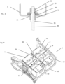
- the battery support 1 includes a tray 10 for receiving one or more batteries.
- the tray 10 is substantially horizontal.
- the tray 10 comprises, for example, and anti-slip surface 11 to ensure the stability of the battery.
- the non-slip surface 11 comprises grooves or embossments.
- the battery support 1 also comprises at least two side walls 12 mounted on two opposite sides of the tray 10.
- the side walls 12 are substantially perpendicular to the tray 10.
- the side walls 12 may include means for attaching the battery support to the vehicle chassis.
- the battery or batteries placed on the tray 10 are held on the battery support 1 by a holding device.
- the holding device comprises a flange 2 and at least one rod 3, a first end 30 of which is threaded.
- the flange 2 comprises a hole 21 for the passage of the first end 30 of the rod 3.
- the second end of the rod 3 is mounted on the tray 10 of the battery support 1.
- the mounting of the rod 3 on the tray 10 is for example done by screwing.
- the flange 2 is held in place on the upper side of the battery or batteries by means of a clamping device 31, 32 mounted on the thread of the rod 3.
- the clamping device is shown in detail in Figure 2 and comprises a sleeve 31 and a nut 32.
- the sleeve 31 comprises a flange 34.
- the sleeve 31 is inserted onto the first end 30 of the rod 3 so that the flange 34 of the sleeve 31 comes to rest on the flange 2.
- the dimensions of the hole 21 in the flange are at least slightly larger than the diameter of the sleeve 31 and strictly smaller than the diameter of the flange 34 of the sleeve 31.
- the nut 32 is then screwed onto the first end 30 of the rod 3 until it comes into contact with the collar 34 of the sleeve 31.
- the surface of the nut 33 in contact with the flange 34 of the sleeve 31 comprises serrations.
- the surface of the collar 34 of the sleeve 31 in contact with the nut during assembly includes serrations.
- the teeth of the nut 32 and the flange 34 are shaped to engage each other.
- the serrations are formed with a flank inclined with respect to the contact surface and a flank substantially perpendicular to the contact surface.
- the angle of the inclined surface of the teeth of the teeth is strictly greater than the angle of the thread of the threaded rod 30.
- the contact surface of the collar 34 of the sleeve 31 with the flange 2 also comprises serrations. They prevent the sleeve 31 from sliding on the contact surface of the flange 2 and thus limits overtightening of the nut 32 on the flange 2.
- the hole of the sleeve 31 may include a groove 38 shaped to slide on grooves 37 formed on the rod 30. The grooves 37 are formed on a portion of the shaft 30 beyond the thread 35.
- the rod 30 may also include a shoulder 36 intended to form a stop for the sleeve 31 when the sleeve 31 is mounted on the rod 30.
- Figure 3 shows the relative position of the flange 2, the rod 30, the nut 31, and the sleeve 31 when the flange 2 is mounted on a battery 4 that is placed on the battery support.
- the flange 2 is mounted on at least one rod 30 through the hole in the flange 2.
- the sleeve 31 is then mounted on the rod 30.
- the spline of the sleeve 31 slides over the grooves of the rod 30.
- the shoulder 36 holds the sleeve 31 onto the threaded rod 30.
- the nut 32 is then screwed onto the thread 35 of the rod 30 until it comes into contact with the teeth of the flange 34 of the sleeve 31.
- the engagement of the teeth of the nut 32 with the teeth of the sleeve 31 forms a mechanical stop ensuring optimal tightening of the flange 2 on the battery and reducing the risk of loosening of the nut 32.
- the battery support according to the invention also comprises an anti-theft device 50, 51.
- This anti-theft device is intended to prevent the removal of the flanges 2 holding the battery or batteries 4 on the tray 10 of the battery support.
- the anti-theft device comprises, for example, a bar 50 ensuring the connection between at least two flanges 2.
- the bar 50 of the anti-theft device is, for example, fixed to the flanges 2 via the nuts 32 of the clamping device.
- the bar 50 can also be fixed by other means which prevent it from being dismantled with conventional tools.
- the nuts 32 of the device can be replaced by nuts having a specific shape incompatible with usual tools and requiring a specific tool for disassembly.
- the bar 50 includes a slot 52 allowing the passage of an arch (or loop) of a rod 51.
- a lock 6 e.g., a padlock
- the rod 51 has two ends 53 each of which is mounted on a threaded rod 30 of the battery support 1.
- each end of the rod 51 may comprise a ring into which the threaded rod 30 is slid.
- the rod 51 is mounted on two adjacent threaded rods 30 before the nuts 32 are placed on the threaded rods 30.
- the flanges 2 are then inserted onto the threaded rods 30.
- the bar 50 is then placed on the two adjacent threaded rods 30 to connect two adjacent flanges 2.
- the arch of the rod 51 is inserted into the slot 52 of the bar 50.
- the sleeves 31 of the locking device are then mounted on the threaded rods 30 so that the bar 50 is gripped between the flange 2 and a sleeve 31.
- the nuts 32 are then screwed onto the threaded rods 30.
- the lock 6 can then be attached to the rod arch 51.
Landscapes
- Engineering & Computer Science (AREA)
- Chemical & Material Sciences (AREA)
- Chemical Kinetics & Catalysis (AREA)
- Electrochemistry (AREA)
- General Chemical & Material Sciences (AREA)
- Mechanical Engineering (AREA)
- Aviation & Aerospace Engineering (AREA)
- Combustion & Propulsion (AREA)
- Transportation (AREA)
- Battery Mounting, Suspending (AREA)
Claims (13)
- Batteriehalterung (1) für ein Kraftfahrzeug, mit einem Träger (10) zur Aufnahme mindestens einer Batterie (4), einer Haltevorrichtung zum Halten der Batterie oder Batterien auf dem Träger, wobei die Haltevorrichtung einen Flansch (2) auf einer Gewindestange (30) und eine Klemmvorrichtung (31, 32) zum Festklemmen des Flansches (2) an der Batterie oder den Batterien umfasst, dadurch gekennzeichnet, dass die Klemmvorrichtung umfasst:- eine Hülse (31), die gleitend auf der Gewindestange (30) angebracht ist und einen Kragen (34) aufweist, der auf dem Flansch aufliegt,- eine Mutter (32), die auf der Gewindestange montiert ist und sich auf dem Kragen der Hülse abstützt, und dass die Kontaktflächen zwischen der Mutter (32) und dem Kragen (34) der Buchse eine Verzahnung aufweisen.
- Batteriehalterung (1) für ein Kraftfahrzeug nach Anspruch 1, wobei die Kontaktfläche zwischen dem Kragen (34) und dem Flansch (2) eine Verzahnung aufweist.
- Batteriehalterung (1) für ein Kraftfahrzeug nach Anspruch 2, wobei die Verzahnung jeweils durch eine zur Kontaktfläche geneigte Flanke und eine zur Kontaktfläche im Wesentlichen senkrechte Flanke gebildet wird.
- Batteriehalterung (1) für ein Kraftfahrzeug nach Anspruch 3, wobei der Winkel der schrägen Flanke der Verzahnung in Bezug auf die Kontaktfläche streng größer ist als der Winkel des Gewindes der Gewindestange (30) in Bezug auf eine Längsachse der Stange (30).
- Batteriehalterung (1) für Kraftfahrzeuge nach einem der vorhergehenden Ansprüche, wobei die Gewindestange (30) im Wesentlichen senkrecht zum Träger (10) angebracht ist.
- Batteriehalterung (1) für ein Kraftfahrzeug nach einem der vorhergehenden Ansprüche, wobei der Flansch (2) im Wesentlichen parallel zum Träger (10) verläuft.
- Batteriehalterung (1) für ein Kraftfahrzeug nach einem der vorhergehenden Ansprüche, wobei die Gewindestange (30) einen Anschlag (36) aufweist, der einen Anschlag für die Hülse (31) bildet, wenn die Hülse (31) auf der Stange montiert ist.
- Batteriehalterung (1) für ein Kraftfahrzeug nach einem der vorhergehenden Ansprüche, wobei der Träger (10) Seitenwände (12) aufweist.
- Batteriehalterung (1) für ein Kraftfahrzeug nach einem der vorhergehenden Ansprüche, wobei der Querschnitt des Flansches (2) U-förmig ist.
- Batteriehalterung (1) für ein Kraftfahrzeug nach einem der vorhergehenden Ansprüche, dadurch gekennzeichnet, dass der Flansch (2) ein erster Flansch ist und die Haltevorrichtung einen zweiten Flansch (2) umfasst, wobei die Batteriehalterung außerdem eine Diebstahlsicherung umfasst, die die Verbindung und Verriegelung der beiden Flansche (2) der Haltevorrichtung mit mindestens zwei Gewindestangen (30) gewährleistet.
- Batteriehalterung (1) für ein Kraftfahrzeug nach dem vorhergehenden Anspruch, wobei die Diebstahlsicherung umfasst:
eine Stange (50), wobei jedes Ende der Stange über die Klemmvorrichtung an einem entsprechenden Flansch der Haltevorrichtung angebracht ist, so dass der Kragen der Hülse (31) auf der Stange (50) zu liegen kommt. - Batteriehalterung (1) für ein Kraftfahrzeug nach dem vorhergehenden Anspruch, wobei die Diebstahlsicherung umfassteine Stange (51), deren beide Enden (53) an den Gewindestangen (30) angebracht sind, dadurch gekennzeichnet, dass die Stange (51) einen Abschnitt aufweist, der einen Bogen bildet,und wobei die Stange einen Schlitz (52) aufweist, der so angeordnet ist, dass er den bogenförmigen Abschnitt der Stange aufnimmt.
- Ein Kraftfahrzeug mit einer Batteriehalterung nach einem der vorhergehenden Ansprüche.
Priority Applications (3)
| Application Number | Priority Date | Filing Date | Title |
|---|---|---|---|
| EP21194163.8A EP4140790B1 (de) | 2021-08-31 | 2021-08-31 | Kraftfahrzeugbatteriehalterung |
| US17/894,340 US12272835B2 (en) | 2021-08-31 | 2022-08-24 | Motor vehicle battery support |
| CN202211049558.XA CN115732838A (zh) | 2021-08-31 | 2022-08-30 | 机动车辆的电池支撑件 |
Applications Claiming Priority (1)
| Application Number | Priority Date | Filing Date | Title |
|---|---|---|---|
| EP21194163.8A EP4140790B1 (de) | 2021-08-31 | 2021-08-31 | Kraftfahrzeugbatteriehalterung |
Publications (3)
| Publication Number | Publication Date |
|---|---|
| EP4140790A1 EP4140790A1 (de) | 2023-03-01 |
| EP4140790C0 EP4140790C0 (de) | 2024-10-09 |
| EP4140790B1 true EP4140790B1 (de) | 2024-10-09 |
Family
ID=77910526
Family Applications (1)
| Application Number | Title | Priority Date | Filing Date |
|---|---|---|---|
| EP21194163.8A Active EP4140790B1 (de) | 2021-08-31 | 2021-08-31 | Kraftfahrzeugbatteriehalterung |
Country Status (3)
| Country | Link |
|---|---|
| US (1) | US12272835B2 (de) |
| EP (1) | EP4140790B1 (de) |
| CN (1) | CN115732838A (de) |
Families Citing this family (3)
| Publication number | Priority date | Publication date | Assignee | Title |
|---|---|---|---|---|
| JP7322914B2 (ja) * | 2021-03-24 | 2023-08-08 | いすゞ自動車株式会社 | 車載機器取付装置 |
| CN115958629B (zh) * | 2021-10-11 | 2025-03-28 | 富泰京精密电子(烟台)有限公司 | 电池固定装置及移动机器人 |
| WO2025012656A1 (en) * | 2023-07-11 | 2025-01-16 | Locks4Vans Ltd | Vehicle battery security |
Family Cites Families (39)
| Publication number | Priority date | Publication date | Assignee | Title |
|---|---|---|---|---|
| US1208236A (en) * | 1916-01-19 | 1916-12-12 | Frank H Thompson | Lock for coupling-nuts. |
| US1577292A (en) * | 1925-01-15 | 1926-03-16 | Claude P Obreiter | Storage-battery theftproof locking device |
| US2791898A (en) * | 1955-07-29 | 1957-05-14 | James R Pegg | Battery lock |
| US2833363A (en) * | 1955-10-07 | 1958-05-06 | Gen Motors Corp | Retainer means for batteries and the like |
| US2849074A (en) * | 1956-07-12 | 1958-08-26 | Gen Motors Corp | Battery retainer means |
| US3498400A (en) * | 1967-11-24 | 1970-03-03 | Herbert Hysmith | Battery locking means |
| US3826115A (en) * | 1972-09-12 | 1974-07-30 | B Davis | Battery locking device |
| US4038843A (en) * | 1976-08-16 | 1977-08-02 | Daley Jr Richard John | Security devices for mounting CB radio, tape player, stereo or the like in motor vehicles |
| US4129194A (en) * | 1977-07-28 | 1978-12-12 | Eaton Corporation | Hold-down device for storage batteries |
| US4191034A (en) * | 1977-10-31 | 1980-03-04 | Jacob Froess | Battery lock |
| US4249403A (en) * | 1979-07-25 | 1981-02-10 | Calvin Littlejohn | Battery locking means |
| US4520887A (en) * | 1983-02-04 | 1985-06-04 | D & S Plug Corporation | Battery holddown arrangement |
| US4535863A (en) * | 1983-08-26 | 1985-08-20 | Becker John R | Battery security and hold-down device |
| JPS60156053U (ja) * | 1984-03-28 | 1985-10-17 | 日産自動車株式会社 | 自動車バツテリの取付構造 |
| US4926953A (en) * | 1984-12-24 | 1990-05-22 | Platt Richard B | Battery hold-down structure |
| US5052198A (en) * | 1990-07-30 | 1991-10-01 | Elektrek Partnership | Battery lock and hold-down device |
| US5409338A (en) * | 1993-05-04 | 1995-04-25 | Hong Kong Disc Lock Company, Limited | Wedge-action lock washer assembly having coupled washers |
| US5377947A (en) * | 1993-08-23 | 1995-01-03 | Johnson; Jerome | Battery holddown |
| JP2922792B2 (ja) * | 1994-09-09 | 1999-07-26 | 株式会社クボタ | 電動カートのバッテリー支持部構造 |
| CN2559823Y (zh) * | 2002-07-31 | 2003-07-09 | 朴明基 | 防松动自锁垫圈 |
| JP3754016B2 (ja) * | 2002-10-16 | 2006-03-08 | 川崎重工業株式会社 | 車両のバッテリー取付構造 |
| FR2894388B1 (fr) * | 2005-12-02 | 2016-01-22 | Renault Sas | Module de generation d'electricite comprenant une pluralite de cellules electrochimiques |
| AU2008200632B2 (en) * | 2007-02-09 | 2011-06-30 | Kangas, Eila Anneli | Locking washer |
| KR20100048444A (ko) * | 2008-10-31 | 2010-05-11 | 현대자동차주식회사 | 톱니붙이 캠와셔와 이를 이용한 차량의 타이밍 체인 커버와실린더블록의 체결구조 |
| FR2961869B1 (fr) * | 2010-06-25 | 2012-08-03 | Ct Tech Des Ind Mecaniques | Rondelle de blocage a double effet |
| FR2968370B1 (fr) * | 2010-12-06 | 2013-09-06 | Airbus Operations Sas | Ecrou comprenant un systeme anti-rotation et dispositif de fixation equipe dudit ecrou |
| CN102705344B (zh) * | 2012-05-23 | 2014-06-25 | 上海萨美锐工业机械有限公司 | 组合式防松垫圈 |
| KR102076971B1 (ko) * | 2012-11-27 | 2020-04-07 | 에스케이이노베이션 주식회사 | 전원 연결장치 및 이를 포함한 배터리 팩 |
| US9540849B2 (en) | 2013-09-27 | 2017-01-10 | Cecil W. Renfro | Commercial motor vehicle and heavy equipment battery locking device and system for use |
| CN103560340A (zh) * | 2013-10-29 | 2014-02-05 | 江苏士林电气设备有限公司 | 一种防松脱的风电母线连接构件 |
| CN103531922A (zh) * | 2013-10-29 | 2014-01-22 | 江苏士林电气设备有限公司 | 一种风电母线连接构件 |
| CN104454912A (zh) * | 2014-12-16 | 2015-03-25 | 武汉武船机电设备有限责任公司 | 一种抗震防松垫圈及螺纹副 |
| DE102015204724A1 (de) * | 2015-03-16 | 2016-09-22 | Volkswagen Aktiengesellschaft | Fortbewegungsmittel und Anordnung zur Anbindung eines elektrochemischen Energiespeichers an ein Bordnetz eines elektrisch antreibbaren Fortbewegungsmittels |
| JP2017013557A (ja) * | 2015-06-29 | 2017-01-19 | スズキ株式会社 | バッテリートレー構造 |
| DE102016015024A1 (de) * | 2016-12-16 | 2017-07-06 | Daimler Ag | Toleranzausgleichende wiederlösbare Verbindung hoch belasteter Bauteile |
| CN106763092A (zh) * | 2017-03-11 | 2017-05-31 | 王金娣 | 一种防松螺母 |
| KR20180131038A (ko) | 2017-05-31 | 2018-12-10 | 천병환 | 락킹와셔를 이용한 볼트 풀림 방지 체결구조 |
| DE102017215086A1 (de) * | 2017-08-29 | 2019-02-28 | Volkswagen Aktiengesellschaft | Vorrichtung zur Befestigung mindestens eines Batteriemoduls an einem Gehäuseboden eines Batteriegehäuses |
| AT521809A1 (de) * | 2018-11-22 | 2020-05-15 | Avl List Gmbh | Isolier- und Befestigungsvorrichtung für ein Brennstoffzellensystem |
-
2021
- 2021-08-31 EP EP21194163.8A patent/EP4140790B1/de active Active
-
2022
- 2022-08-24 US US17/894,340 patent/US12272835B2/en active Active
- 2022-08-30 CN CN202211049558.XA patent/CN115732838A/zh active Pending
Also Published As
| Publication number | Publication date |
|---|---|
| US12272835B2 (en) | 2025-04-08 |
| EP4140790C0 (de) | 2024-10-09 |
| US20230068558A1 (en) | 2023-03-02 |
| CN115732838A (zh) | 2023-03-03 |
| EP4140790A1 (de) | 2023-03-01 |
Similar Documents
| Publication | Publication Date | Title |
|---|---|---|
| US12272835B2 (en) | Motor vehicle battery support | |
| US7726681B2 (en) | System and method for preventing rattling in receiver hitch arrangement | |
| US7600774B1 (en) | Cam action tightening receiver hitch assembly | |
| EP3571081B1 (de) | Aufhängungsvorrichtung | |
| US3241408A (en) | Vehicle wheel nut or bolt | |
| US8419041B2 (en) | Hitch | |
| US4284114A (en) | Locking member for a clamping bolt | |
| CA2375212A1 (en) | Structure for preventing loosening of threaded fasteners | |
| CN110576801A (zh) | 用于负载载架的扩展模块 | |
| US6908254B2 (en) | Cam nut adjustment apparatus and method | |
| WO2010037547A1 (en) | Wheel nut locks | |
| JP2010003583A (ja) | バッテリーターミナル | |
| US4493597A (en) | Nut lock assembly | |
| EP1610007B1 (de) | Festziehensystems für einen sicheren Anschluß von mindestens zwei Elementen | |
| EP2754902A2 (de) | Schraubverbindungssystem | |
| EP1498616B1 (de) | Über einen Zwischenraum aneinander Befestigen von Elementen | |
| JP7620729B2 (ja) | コンパクトな空間で小さい締付トルクで押上げられるフック緩衝装置の取り付け構造 | |
| CN104421247A (zh) | 一种气缸耳轴支撑结构 | |
| JP3572491B2 (ja) | ナットおよびその締結用工具 | |
| JP2009034733A (ja) | ボルト/ナットの供回り防止具 | |
| US20200376634A1 (en) | Lockable socket insert, insert tool and insert lock and method of making and using the same | |
| KR100325752B1 (ko) | 자동차의 배터리 고정장치 | |
| US20080226416A1 (en) | Anti-Rotation Device | |
| KR0137398Y1 (ko) | 스티어링 휠 유격 조정용 툴 | |
| US4371212A (en) | Wheel rim bolt attachment |
Legal Events
| Date | Code | Title | Description |
|---|---|---|---|
| PUAI | Public reference made under article 153(3) epc to a published international application that has entered the european phase |
Free format text: ORIGINAL CODE: 0009012 |
|
| STAA | Information on the status of an ep patent application or granted ep patent |
Free format text: STATUS: THE APPLICATION HAS BEEN PUBLISHED |
|
| AK | Designated contracting states |
Kind code of ref document: A1 Designated state(s): AL AT BE BG CH CY CZ DE DK EE ES FI FR GB GR HR HU IE IS IT LI LT LU LV MC MK MT NL NO PL PT RO RS SE SI SK SM TR |
|
| STAA | Information on the status of an ep patent application or granted ep patent |
Free format text: STATUS: REQUEST FOR EXAMINATION WAS MADE |
|
| 17P | Request for examination filed |
Effective date: 20230830 |
|
| RBV | Designated contracting states (corrected) |
Designated state(s): AL AT BE BG CH CY CZ DE DK EE ES FI FR GB GR HR HU IE IS IT LI LT LU LV MC MK MT NL NO PL PT RO RS SE SI SK SM TR |
|
| GRAP | Despatch of communication of intention to grant a patent |
Free format text: ORIGINAL CODE: EPIDOSNIGR1 |
|
| STAA | Information on the status of an ep patent application or granted ep patent |
Free format text: STATUS: GRANT OF PATENT IS INTENDED |
|
| RIC1 | Information provided on ipc code assigned before grant |
Ipc: H01M 50/264 20210101ALN20231218BHEP Ipc: H01M 50/249 20210101ALN20231218BHEP Ipc: H01M 50/20 20210101ALN20231218BHEP Ipc: B60R 16/04 20060101ALI20231218BHEP Ipc: B60K 1/04 20190101AFI20231218BHEP |
|
| INTG | Intention to grant announced |
Effective date: 20240112 |
|
| GRAJ | Information related to disapproval of communication of intention to grant by the applicant or resumption of examination proceedings by the epo deleted |
Free format text: ORIGINAL CODE: EPIDOSDIGR1 |
|
| STAA | Information on the status of an ep patent application or granted ep patent |
Free format text: STATUS: REQUEST FOR EXAMINATION WAS MADE |
|
| INTC | Intention to grant announced (deleted) | ||
| RIC1 | Information provided on ipc code assigned before grant |
Ipc: H01M 50/264 20210101ALN20240415BHEP Ipc: H01M 50/249 20210101ALN20240415BHEP Ipc: H01M 50/20 20210101ALN20240415BHEP Ipc: B60R 16/04 20060101ALI20240415BHEP Ipc: B60K 1/04 20190101AFI20240415BHEP |
|
| GRAP | Despatch of communication of intention to grant a patent |
Free format text: ORIGINAL CODE: EPIDOSNIGR1 |
|
| STAA | Information on the status of an ep patent application or granted ep patent |
Free format text: STATUS: GRANT OF PATENT IS INTENDED |
|
| INTG | Intention to grant announced |
Effective date: 20240607 |
|
| RIC1 | Information provided on ipc code assigned before grant |
Ipc: H01M 50/264 20210101ALN20240524BHEP Ipc: H01M 50/249 20210101ALN20240524BHEP Ipc: H01M 50/20 20210101ALN20240524BHEP Ipc: B60R 16/04 20060101ALI20240524BHEP Ipc: B60K 1/04 20190101AFI20240524BHEP |
|
| GRAS | Grant fee paid |
Free format text: ORIGINAL CODE: EPIDOSNIGR3 |
|
| GRAA | (expected) grant |
Free format text: ORIGINAL CODE: 0009210 |
|
| STAA | Information on the status of an ep patent application or granted ep patent |
Free format text: STATUS: THE PATENT HAS BEEN GRANTED |
|
| AK | Designated contracting states |
Kind code of ref document: B1 Designated state(s): AL AT BE BG CH CY CZ DE DK EE ES FI FR GB GR HR HU IE IS IT LI LT LU LV MC MK MT NL NO PL PT RO RS SE SI SK SM TR |
|
| REG | Reference to a national code |
Ref country code: CH Ref legal event code: EP |
|
| REG | Reference to a national code |
Ref country code: DE Ref legal event code: R096 Ref document number: 602021019843 Country of ref document: DE |
|
| REG | Reference to a national code |
Ref country code: IE Ref legal event code: FG4D |
|
| U01 | Request for unitary effect filed |
Effective date: 20241029 |
|
| U07 | Unitary effect registered |
Designated state(s): AT BE BG DE DK EE FI FR IT LT LU LV MT NL PT RO SE SI Effective date: 20241111 |
|
| PG25 | Lapsed in a contracting state [announced via postgrant information from national office to epo] |
Ref country code: HR Free format text: LAPSE BECAUSE OF FAILURE TO SUBMIT A TRANSLATION OF THE DESCRIPTION OR TO PAY THE FEE WITHIN THE PRESCRIBED TIME-LIMIT Effective date: 20241009 Ref country code: IS Free format text: LAPSE BECAUSE OF FAILURE TO SUBMIT A TRANSLATION OF THE DESCRIPTION OR TO PAY THE FEE WITHIN THE PRESCRIBED TIME-LIMIT Effective date: 20250209 |
|
| PG25 | Lapsed in a contracting state [announced via postgrant information from national office to epo] |
Ref country code: ES Free format text: LAPSE BECAUSE OF FAILURE TO SUBMIT A TRANSLATION OF THE DESCRIPTION OR TO PAY THE FEE WITHIN THE PRESCRIBED TIME-LIMIT Effective date: 20241009 |
|
| PG25 | Lapsed in a contracting state [announced via postgrant information from national office to epo] |
Ref country code: NO Free format text: LAPSE BECAUSE OF FAILURE TO SUBMIT A TRANSLATION OF THE DESCRIPTION OR TO PAY THE FEE WITHIN THE PRESCRIBED TIME-LIMIT Effective date: 20250109 |
|
| PG25 | Lapsed in a contracting state [announced via postgrant information from national office to epo] |
Ref country code: GR Free format text: LAPSE BECAUSE OF FAILURE TO SUBMIT A TRANSLATION OF THE DESCRIPTION OR TO PAY THE FEE WITHIN THE PRESCRIBED TIME-LIMIT Effective date: 20250110 |
|
| PG25 | Lapsed in a contracting state [announced via postgrant information from national office to epo] |
Ref country code: PL Free format text: LAPSE BECAUSE OF FAILURE TO SUBMIT A TRANSLATION OF THE DESCRIPTION OR TO PAY THE FEE WITHIN THE PRESCRIBED TIME-LIMIT Effective date: 20241009 |
|
| PG25 | Lapsed in a contracting state [announced via postgrant information from national office to epo] |
Ref country code: RS Free format text: LAPSE BECAUSE OF FAILURE TO SUBMIT A TRANSLATION OF THE DESCRIPTION OR TO PAY THE FEE WITHIN THE PRESCRIBED TIME-LIMIT Effective date: 20250109 |
|
| PG25 | Lapsed in a contracting state [announced via postgrant information from national office to epo] |
Ref country code: SM Free format text: LAPSE BECAUSE OF FAILURE TO SUBMIT A TRANSLATION OF THE DESCRIPTION OR TO PAY THE FEE WITHIN THE PRESCRIBED TIME-LIMIT Effective date: 20241009 |
|
| PG25 | Lapsed in a contracting state [announced via postgrant information from national office to epo] |
Ref country code: SK Free format text: LAPSE BECAUSE OF FAILURE TO SUBMIT A TRANSLATION OF THE DESCRIPTION OR TO PAY THE FEE WITHIN THE PRESCRIBED TIME-LIMIT Effective date: 20241009 |
|
| PG25 | Lapsed in a contracting state [announced via postgrant information from national office to epo] |
Ref country code: CZ Free format text: LAPSE BECAUSE OF FAILURE TO SUBMIT A TRANSLATION OF THE DESCRIPTION OR TO PAY THE FEE WITHIN THE PRESCRIBED TIME-LIMIT Effective date: 20241009 |
|
| PLBE | No opposition filed within time limit |
Free format text: ORIGINAL CODE: 0009261 |
|
| STAA | Information on the status of an ep patent application or granted ep patent |
Free format text: STATUS: NO OPPOSITION FILED WITHIN TIME LIMIT |
|
| 26N | No opposition filed |
Effective date: 20250710 |
|
| U20 | Renewal fee for the european patent with unitary effect paid |
Year of fee payment: 5 Effective date: 20250825 |
|
| REG | Reference to a national code |
Ref country code: CH Ref legal event code: H13 Free format text: ST27 STATUS EVENT CODE: U-0-0-H10-H13 (AS PROVIDED BY THE NATIONAL OFFICE) Effective date: 20260324 |