EP4140652A1 - Outil pour enfoncer des organes de fixation à dispositif de sécurité amélioré - Google Patents
Outil pour enfoncer des organes de fixation à dispositif de sécurité amélioré Download PDFInfo
- Publication number
- EP4140652A1 EP4140652A1 EP22199668.9A EP22199668A EP4140652A1 EP 4140652 A1 EP4140652 A1 EP 4140652A1 EP 22199668 A EP22199668 A EP 22199668A EP 4140652 A1 EP4140652 A1 EP 4140652A1
- Authority
- EP
- European Patent Office
- Prior art keywords
- connection
- tool
- trip
- activation
- gas pressure
- Prior art date
- Legal status (The legal status is an assumption and is not a legal conclusion. Google has not performed a legal analysis and makes no representation as to the accuracy of the status listed.)
- Pending
Links
Images


Classifications
-
- B—PERFORMING OPERATIONS; TRANSPORTING
- B25—HAND TOOLS; PORTABLE POWER-DRIVEN TOOLS; MANIPULATORS
- B25C—HAND-HELD NAILING OR STAPLING TOOLS; MANUALLY OPERATED PORTABLE STAPLING TOOLS
- B25C1/00—Hand-held nailing tools; Nail feeding devices
- B25C1/008—Safety devices
-
- B—PERFORMING OPERATIONS; TRANSPORTING
- B25—HAND TOOLS; PORTABLE POWER-DRIVEN TOOLS; MANIPULATORS
- B25C—HAND-HELD NAILING OR STAPLING TOOLS; MANUALLY OPERATED PORTABLE STAPLING TOOLS
- B25C1/00—Hand-held nailing tools; Nail feeding devices
- B25C1/04—Hand-held nailing tools; Nail feeding devices operated by fluid pressure, e.g. by air pressure
- B25C1/047—Mechanical details
Definitions
- the invention relates to a drive-in tool for driving fastening means into a workpiece by means of drive-in cycles where a safety device is to prevent unintentional tripping after a predetermined time when the trigger is actuated.
- a generic drive-in tool is shown in DE 10 2013 106 657 Al which is a valuable contribution to the prior art.
- a safety device designated there as a resetting arrangement, is activated by a first drive cycle which is carried out in the single trip mode which is named as such in this case.
- the safety device transfers the tool into a secured state after a pre-determined delay time insofar as the trigger remains pressed and insofar as no drive cycle takes place within the delay time.
- EP 2 767 365 Al relates to a pneumatic nail gun which, among other things, comprises a second control valve which, when the tripper is actuated, is driven independently of an actuation of the contact sensor, a chamber which is either ventilated or vented by means of a throttle when the second control valve is actuated, and a blocking piston which is displaced from an idle position into a blocking position when the pressure in the chamber passes a pre-determined pressure threshold, and which prevents the tripping of a drive-in operation in the blocking position.
- the object of the present invention was to improve the disadvantages of the prior art, in particular to increase the flexibility of tool use and at the same time to ensure comparable safety.
- a drive-in tool for driving fastening means into a workpiece wherein the tool comprises:
- the object is further achieved in particular by a method for driving fastening means into a workpiece
- the flexibility of the tool use is increased, as the safety device is activatable independently of the state of the workpiece contact element and consequently a first single trip mode drive-in cycle does not have to be performed first of all in order to activate the safety device for the first time.
- the user is able to operate the tool from the start after choosing single trip mode or contact release mode (an operating mode in which drive-in operations are able to be tripped within the delay time of the safety device by successively placing and actuating the workpiece contact element with the trigger element held pressed in each case).
- the tool comprises an activation element for this purpose by means of which an activation of the safety device is coupled with the trip movement by the displacement of the activation element by the trigger element when the trigger element is pressed being utilized to cause the safety device to be activated.
- Fastening means are, for example, nails, pins or special screws that are able to be driven-in.
- Wood, metal or concrete can be considered as the workpiece.
- the actuator unit is a pneumatic actuator unit where the expenditure of force necessary for the driving-in is provided purely from pneumatic energy.
- the actuator unit comprises an operating piston which is guided in an operating cylinder.
- the actuator unit comprises a main trip valve, in a preferred manner a non-return valve, by means of which the operating cylinder is tillable abruptly with compressed air such that the drive-in piston is moved in the direction of the tool tip.
- the operating piston is connected to a drive-in piston which acts upon the fastening means to be driven-in.
- a drive-in cycle is a recurring sequence which the actuator unit carries out for consecutively driving-in fastening means.
- control volume is an interior of the tool which is set up for the temporary storage of pneumatic energy.
- it is arranged directly adjoining the tool working cylinder which contains the working piston.
- it surrounds the lateral surface of the operating cylinder completely by 360° at least in one region.
- the tool comprises a ventilation arrangement (e.g., openings in the operating cylinder), by means of which the control volume is tillable with compressed air during the course of the drive-in operation.
- the trigger element for example, can be pivo table or linearly displaceable, e.g., a lever or knob. In a preferred manner, it is pre-stressed into the idle state by means of a spring. In a preferred manner, the trigger element is set up to activate the safety device by a change from its idle state into the pressed state (even) when the workpiece contact element is not actuated.
- one position from the first and the second position of the activation element is an activation position for activating the safety device, i.e., a change in the activation element from the other position into the activation position allows a delay time to start to elapse before the safety device then transfers the tool into the secured state.
- the activation element is in the activation position when the trigger element is in the pressed state.
- pneumatic connection between two locations/ objects is to be understood in a preferred manner as a fluid-permeable pathway (from start to finish) or, where applicable, as the sum of all the fluid-permeable pathways which, where applicable, connects or connect the two locations/ objects together such that fluid is able to flow from the one to the other location / object.
- the pneumatic connection produced from the charging connection and the discharging connection which is provided by means of the activation element in the activation position, is the connection which comprises the smallest cross sectional flow area which, together with the gas pressure of the gas pressure source connection, determines the delay time.
- said connection is the discharging connection, i.e., by means of which air from the control volume flows to the pressure sink.
- the discharging connection extends through one, in a preferred manner two openings in the activation element (in a preferred manner present in a lateral surface of an activation element which is realized as a tube piece).
- said opening forms a smallest cross sectional flow area which, together with the gas pressure, defines the predetermined delay time.
- an adjusting needle which forms a needle valve is arranged in said opening, said adjusting needle in a preferred manner being conically tapered and it consequently being possible to modify the cross sectional flow area of the opening by displacing the needle, e.g., by means of rotating an adjusting screw on which the needle is arranged.
- the charging connection and/ or the discharging connection are delimited in a preferred manner by one or several of the following components, i.e., for example, the connection extends along the corresponding element and/ or through an opening or groove (e.g., between two O-ring seals) of the corresponding element: activation element, housing of the trip valve (see below), standby element (see below) and trip element.
- the one connection produced from the charging connection and the discharging connection comprises a high flow resistance which enables slow discharging or charging (depending on the case).
- the safety device is set up to transfer the tool from the secured state into the trip-ready state (and in a preferred manner to keep the same stable in said state), when the tool is connected to an energy supply and the trigger element is situated in the idle state thereof.
- the trip-ready state of the tool is defined as a standard state such that the user finds the instrument with the trigger not pressed and the energy source connected in the trip-ready state and the trip-ready state does not only have to be achieved by a first special drive-in cycle (e.g., single tripping).
- An activation of the safety device is to be understood in a preferred manner as an activation of a countdown, the countdown running for as long as the safety device is activated-the safety device is deactivated in a preferred manner by being reset (either by a drive-in operation or by the trigger-or in a preferred variant according to figs. 10-12 the trigger element and the workpiece contact element-being transferred into the idle state again) or by the pre-determined time elapsing. I.e., a countdown runs in the activated state of the safety device, whilst in the deactivated state no countdown runs. In the deactivated state of the safety device the tool is able to be situated in the secured or in the trip-ready state-both are possible.
- the safety device is resettable as a result of a drive-in cycle (the drive-in cycle is only possible as long as the safety device has not yet brought about a transfer of the tool into the secured state) or as a result of a change of the trigger element- or in a preferred variant according to figs.-12: the trigger element and the workpiece contact element-from the pressed state into its idle state.
- the user is able to keep the instrument in the standby state by means of each of said two actions.
- the correspondingly other connection from the charging connection and the discharging connection comprises a larger smallest cross-sectional flow area than the one connection from the charging connection and the discharging connection.
- a stronger gas flow flows through the correspondingly other pneumatic connection at the same applied pressure than in the one connection.
- the non-secured state can be assumed again quicker, i.e., within a shorter time period than the delay time, which, for example, in the case of a sufficiently large minimal cross sectional flow area of the other connection from the charging connection and the discharging connection can even be immediately perceptible.
- the other connection from the charging connection and the discharging connection comprises a low flow resistance which enables rapid discharging or charging (depending on the case).
- the smallest cross sectional flow area which, together with the gas pressure, determines the delay time of the safety device, is arranged in precisely one of the following pneumatic connections:
- the tool comprises a pneumatic line which is both part of the charging connection and part of the discharging connection and which extends from the activation element toward the control volume, and wherein the tool further comprises two lines which are separate from one another, wherein one of the lines which are separate from one another is part of the charging connection and in a preferred manner is not part of the discharging connection and extends from the activation element toward the gas pressure source connection and the other of the lines which are separate from one another is part of the discharging connection and in a preferred manner is not part of the charging connection and extends from the activation element toward the pressure sink, wherein the smallest cross-sectional flow area, which, together with the gas pressure, determines the delay time of the safety device, is present in precisely one of the lines which are separate from one another.
- a Y configuration is provided with the activation element as the node point, by means of which the different cross sectional flow areas of the discharging and charging connection are realizable in a structurally advantageous manner.
- the tool comprises in a preferred manner a bridging line and the smallest cross section flow area is situated in the common line and is bridged or connected in parallel by means of the bridging line in a position (from the first and second position) of the activation element and is not bridged or connected in parallel in the other position of the activation element such that on the whole a larger cross sectional flow area is produced in the one position than in the other position.
- the safety device is set up to transfer the tool into the secured state if a pressure threshold in the control volume is fallen below.
- the tool is correspondingly transferred into the secured state.
- the safety of the tool is further increased as a lower pressure provides a more stable state than a higher pressure and the tool, striving for the more stable state (also generally in the event of malfunctions), is consequently blocked more securely should unexpected failures occur in any components (e.g., control volume leakage).
- the charging connection is present when the trigger element (and in a preferred manner the workpiece contact element) is situated in its idle state.
- the control volume is filled with compressed air when the trigger element (and in a preferred manner the workpiece contact element) is in its idle state.
- control volume is fillable with the trigger element released (and in a preferred manner with the workpiece contact element not actuated) such that in the trip-ready state a high air pressure is present in the control volume.
- the trip arrangement comprises a trip valve which is coupled, preferably mechanically, with the trigger element.
- a trip valve is operated by means of the trigger element.
- component parts of the trip valve are one or several of the following components: trip valve housing, activation element, trip element (see below) and standby element.
- the trip valve is coupled with the trigger element purely mechanically by means of solid bodies (without fluid).
- the trip valve is accommodated in a trip valve housing which is separate to the housing of the tool and is consequently simple to replace or retrofit.
- the activation element in a preferred manner also the standby element, in a preferred manner also the trip element, is accommodated in the trip valve housing.
- the activation element, in a preferred manner also the standby element, in a preferred manner also the trip element is in each case in a preferred manner part of the trip valve.
- the trip valve housing is sleeve-shaped in a preferred manner with a front region which faces the trigger element and a rear region which is remote from the trigger element. On the front side it comprises in a preferred manner an open end face and on the rear side a substantially closed end face. In a preferred manner, the tool comprises a venting line for the preferred permanent connection of a volume which is (also) defined by the rear region of the trip valve housing.
- this is a line provided in the tool housing, in a particularly preferred manner, however, a line which is defined by the trip valve (and is consequently simple to retrofit) and which in a preferred manner extends from the rear region toward the front region, e.g., an axial channel in the trip element (see below) or an axial channel or a preferred outer axial groove in the trip valve housing.
- control volume is realized by means of the trip valve.
- This provides a compact design of the safety device which is also easily retro-fittable by means of replacing a conventional trip valve by a trip valve according to the invention.
- An existing tool housing can consequently continue to be utilized and it is not necessary to modify the tool housing (to a large extent or at all) in order to provide the control volume.
- the term realize is to be understood in a preferred manner as a housing and/ or one or several component parts of the trip valve defining a space which is controllable in a fluid-technical manner per discharging connection and charging connection. This does not exclude existing spaces in the tool housing being able to define parts of the control volume.
- control volume in a preferred manner, in this case, however, more than 50%, in a preferred manner 75% and in a quite preferred manner 90% of the control volume is realized by the trip valve or only tool housing regions which are directly adjacent the trip valve defines the control volume. In a particularly preferred manner, the control volume is completely integrated into the trip valve. It is particularly preferred in this case when an adjusting needle is arranged as mentioned beforehand in the opening or the cross section which determines the delay time of the safety device, as then the control volume can be designed to be very small and space-saving.
- the trip valve defines a pneumatic connection which
- control volume can be reset by means of the trip valve in the state of the tripping of a drive-in operation. It is consequently not necessary to provide a separate line or connection from the drive-in piston to the control volume or indirect control of a control volume ventilation/venting means by means of a pressure tapped from the drive-in piston.
- This is possible as according to the invention use is made of the movement of the components of the trip valve which are present in any case in order to bring about the ventilation/venting of the control volume.
- an advantage in this case is that the resetting of the control volume is effected in a more secure manner as the resetting is brought about in a more direct manner, and not in an indirect manner by means of the drive-in piston.
- the drive-in piston could move back into its starting position again too quickly and consequently the gas pressure in the control volume would only be partially reset.
- the dwelling of the trigger and the workpiece contact element in the pressed or actuated position is slower on account of the direct human interaction and consequently provides a longer time for ventilating/venting the control volume.
- the contact trip mode is advantageously enabled as a result of resetting the control volume (i.e., moving into the state in which it is situated when the gas pressure is connected, the trigger element not pressed and the workpiece contact element not actuated).
- connection from the loading connection and the discharging connection which comprises the smallest cross-sectional flow area is present both in the first position of the activation element and in the second position of the activation element.
- the complexity of the activation element is reduced with reference to said functionality as it does not have to switch between the connections, but is to be able to disconnect and connect only one of said connections.
- the one connection from the loading connection and the discharging connection which comprises the smallest cross-sectional flow area is present in each state of the tool and its components.
- the activation element is additionally changeable between the first and the second position by means of the workpiece contact element.
- the activation element is additionally changed correspondingly between said two positions by means of the workpiece contact element.
- the activation element is movable into the one position (in a preferred manner the activation position) by the trigger element or the workpiece contact element, i.e., actuation of one of said elements is sufficient, both elements can also be actuated. In contrast, both elements have to be non-actuated so that the activation element is able to assume the other position again.
- the activation element is resettable pneumatically into the position from its first and second position in which the activation element is situated in the idle state of the trigger element.
- the activation element is moved pneumatically in the direction of the corresponding position.
- the activation element comprises a surface difference of surfaces which are acted upon by gas from the gas pressure source connection less surfaces which are connected to the pressure sink, the surface difference being positive.
- the safety device comprises a standby element which is displaceable pneumatically into a safety position and a standby position, wherein the tool is in the secured state when the standby element is in the safety position, and wherein the tool is in the triggered state when the standby element is in the standby position.
- the safety device transfers the drive-in tool from the tripped state into the secured state by means of pneumatically displacing a standby element from a standby into a safety position.
- the standby element is arranged, in particular in a pneumatic or fluidic manner, between the control volume and the gas pressure source connection and the charging connection is guided through an opening in the standby element.
- gas from the gas pressure source connection is guided through an opening in the standby element and on to the control volume.
- control volume is fillable with air by means of the standby element-in contrast to the drive-in tool named in the introduction where the control volume is only filled by means of the operating piston, it is consequently also possible to fill the control volume without any drive-in cycle.
- a structure is obtained by means of which pneumatic safety is able to be achieved as the standby element provides part of the charging connection.
- the standby element comprises,
- the position of the standby element is determined by two antagonistically acting surface regions and the pressure difference between the pressure in the control volume and the pressure in the gas pressure source.
- the gas pressure source is substantially constant, the position of the standby element is consequently substantially dependent on the change in pressure in the control volume.
- the first surface area is larger than the second surface area.
- the standby element is realized as a tube piece which is open at both end faces and comprises a central through channel.
- the tube piece comprises different outside diameters. It is displaceably mounted in a valve housing in a preferred manner.
- the valve housing also comprises in a preferred manner analogously corresponding, different inside diameters. The different diameters enable a simple realization of antagonistically acting surface regions with different surface areas.
- the tube piece comprises, along with the through channel, an axial secondary channel which comprises an inner opening, which faces the through channel and in a preferred manner is radial, and an outer opening, which is at an axial spacing from said inner opening, faces the outside surrounding area of the tube piece and in a preferred manner is radial.
- a gas flow is directed from the gas pressure source connection through the corresponding axial secondary channel of the tube piece for charging the control volume.
- the two openings in each case form the end of the axial secondary channel.
- the activation element together with the standby element are arranged as a trip valve or as part of the trip valve of the trip arrangement in a trip valve housing which is insertable into a tool housing.
- the substantial movable parts of the safety device (activation element, standby element) are combined as a compact assembly which is consequently simple to mount, space-saving and/ or retro-fittable.
- the activation element is movably guided on the standby element and relative to the standby element. In a further method according to the invention, the activation element is guided in a corresponding manner.
- the activation element and standby element interact directly with one another in this manner and no additional guiding parts have to be provided.
- the activation element is received by the standby element.
- a contour of the activation element or a sealing element (e.g., sealing rings) of the activation element abuts (directly) against a contour of the standby element or against a sealing element (e.g., sealing ring) of the standby element.
- the activation element and the standby element are nested in one another and in a preferred manner are concentric.
- the design is very compact.
- the activation element is received concentrically in the standby element which is realized as a tube piece, an outside contour of the activation element or outer sealing elements (e.g., sealing rings) of the activation element abut (directly) against the inside contour of the standby element or against inner sealing elements (e.g., sealing rings) of the standby element.
- the activation element is set up in the second position to interrupt the charging connection.
- the charging connection is interrupted by the activation element in the second position.
- control volume is disconnected from the gas pressure source by means of the activation element in dependence on the trigger position such that the gas pressure in the control volume is able to be changed from that of the gas pressure source.
- the tool comprises a main trip valve and the tool comprises a trip element which is set up to interrupt a pneumatic connection, referred to below as a trip connection, from the gas pressure source connection to the main trip valve when the standby element is in the standby position, and wherein by means of the standby element a pneumatic secondary line is provided between the main trip valve and the gas pressure source connection by bypassing the trip element when the standby element is in the safety position.
- a trip connection is correspondingly interrupted by means of a trip element of a main trip valve and a pneumatic secondary line is correspondingly provided.
- a trip taking place is pneumatically prevented when the standby element is in the safety position.
- a trip is possible by means of the trip element when the standby element is in the standby position.
- such a secondary line also exists when the standby element is in the standby position and the activation element is not in the activation position.
- the trip element is set up to define a pneumatic trip discharging connection between the main trip valve and a pressure sink (and not only to interrupt the trip connection), when the standby element is in the standby position.
- the trip element assumes a double function, as a result of which a compact design is made possible.
- the trigger element comprises a coupling element which can be acted upon by the workpiece contact element, in a preferred manner in any position of the trip element, and which couples the workpiece contact element mechanically with the trip element.
- the trip element in a preferred manner, is a pin.
- the trip element comprises sealing surfaces (e.g., sealing rings).
- the trip element comprises in a preferred manner an idle position and a trip position.
- the trip connection is only interrupted when the activation element is in one of its two positions (e.g., the second position or the activation position) AND the trip element is in the trip position.
- the activation element also has a trip function when it is moved into the corresponding position, insofar as the trip element is already in the trip position.
- the trip element in a preferred manner, is part of the trip valve.
- the trip element in a preferred manner, comprises a central axial channel.
- a venting line is provided for the preferred permanent connection of the volume which is defined by the rear region of the trip valve housing (see below for more concerning the venting line).
- the trip element in a preferred manner, is acted upon at one end by means of a spring in the direction of the trigger element. It can be acted upon at (another) end in a preferred manner by means of a coupling element which is movable as a result of movements of the trigger element and of the workpiece contact element.
- the activation element defines part of the trip connection between the gas pressure source connection and the main trip valve.
- the trip element is/will be movably guided on the activation element and relative to the activation element.
- a compact design is obtained as the trip element and the activation element interact directly with one another in this manner and no additional guiding parts have to be provided.
- a contour of the activation element or a sealing element (e.g., sealing rings) of the activation element abuts (directly) against a contour of the trip element or against a sealing element (e.g., sealing ring) of the trip element.
- the activation element and a trip element for tripping a main trip valve of the tool in a preferred manner the already named trip element, are nested in one another and in a preferred manner are concentric.
- the design is very compact, in particular in the axial direction (direction of movement of the activation element and/ or standby element and/ or trip element).
- an outside contour of the trip element or outer sealing elements (e.g., sealing rings) of the trip element abut (directly) against the inside contour of the activation element or against inner sealing elements (e.g., sealing rings) of the activation element.
- the activation element in a preferred manner, is realized as a tube piece and it guides the trip element within itself.
- Fig. 1a, 1b show a schematic diagram of a tool 1 according to the invention for driving fastening means 90 into a workpiece 91.
- the tool 1 comprises:
- a pneumatic connection is defined between the control volume 15 and the gas pressure source connection 23, which is hereafter referred to as charging connection 27.1.
- a pneumatic connection is defined between the control volume 15 and a pressure sink 40, which is hereafter referred to as discharging connection 33.1.
- One connection from the charging connection 27.1 and the discharging connection 33.1, here the discharging connection 33.1, comprises a smallest cross-sectional flow area 33.8 which, together with a gas pressure of the gas pressure source, determines the delay time of the safety device.
- the safety device 8 of the tool 1 functions as follows.
- the control volume 15 is charged by means of the charging connection 27.1. If the user, proceeding from fig. la, presses the trigger 6, the activation element 33 is displaced such that the charging connection 27.1 is disconnected and the discharging connection 33.1 is established (fig. lb).
- the control volume 15 is discharged slowly, i.e., at the determined delay time. Dependent on the pressure in the control volume 15, the tool 1 is then moved into a trip-ready state or a secured state.
- Said figures additionally show the preferred development, according to which the correspondingly other connection from the charging connection 27.1 and the discharging connection 33.1, i.e., here the charging connection 27.1, comprises a larger smallest cross sectional flow area than the one connection from the charging connection 27.1 and the discharging connection 33.1, i.e., here the discharging connection 33.1, as a result of which the control volume 15 is able to be charged very rapidly.
- the tool 1 comprises a pneumatic line which is both part of the charging connection 27.1 and part of the discharging connection 33.1 and which extends from the activation element 33 toward the control volume 15.
- the tool 1 additionally comprises two lines which are separate from one another, wherein one of the lines which are separate from one another is part of the charging connection 27.1 and extends from the activation element 33 toward the gas pressure source connection 23 and the other of the lines which are separate from one another is part of the discharging connection 33.1 and extends from the activation element 33 toward the pressure sink 40.
- the smallest cross sectional flow area 33.8 which, together with the gas pressure, determines the delay time of the safety device 8, is present in precisely one of the lines which are separate from one another, here in the line which extends from the activation element 33 toward the pressure sink 40.
- the rapid charging and slow discharging of the control volume 15 is realized structurally in a very advantageous manner as a result.
- the safety device 8 is set up to transfer the tool 1 into the secured state if a pressure threshold in the control volume is fallen below and that the charging connection 27.1 is present when the trigger element 6 is in its idle state 600.
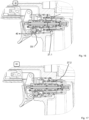
- Fig. 2 - fig. 8 show sectional representations of an even more preferred embodiment of a tool 1 based on figs. la, lb in different states. It has the features described and shown in fig. la and fig. lb.
- Figs. 2 and 3 show the tool 1 when the compressed air is not connected, the standby element 27 is situated in the safety position.
- Fig. 4 shows the tool 1 with the compressed air connected, neither the trigger element 6 nor the workpiece contact element 7 being actuated-the standby element 27 is situated in the standby position.
- Fig. 5 shows the tool 1 with the trigger element 6 pressed and with the standby element 27 still in the standby position,
- fig. 6 shows the tool 1, after the predetermined time has elapsed and the tool 1 has been transferred into the secured state, the standby element 27 is now situated in the safety position.
- Fig. 7 shows the tool 1 in the state of tripping a drive-in operation, the standby element 27 in this case is in the standby position,
- fig. 8 shows the tool with the trigger element 6 and the workpiece contact element 7 pressed, it being situated in the secured state-the standby element 27 is situated in the safety position-and consequently no drive-in operation is tripped.
- the activation element 33 is resettable pneumatically in the position from its first and second position in which the activation element 33 is situated in the idle state 600 of the trigger element 6.
- the activation element 33 comprises a positive surface difference between surfaces which are acted upon by gas from the gas pressure source connection less surfaces which are connected to the pressure sink 40.
- the safety device 8 comprises a standby element 27 which is displaceable pneumatically into a safety position and a standby position.
- the tool 1 is situated in the secured state ( figs. 2, 3 , 6 , 8 ) when the standby element 27 is situated in the safety position, and it is situated in the trip-ready state 100 ( figs. 4, 5 , 7 ) when the standby element 27 is situated in the standby position.
- the standby element 27 is arranged between the control volume 15 and the gas pressure source 23 and the charging connection 27.1 is guided through at least two openings in the standby element 27 ( fig. 4 ).
- the standby element 27 comprises a first surface region with a first surface area Al which can be acted upon by gas pressure from the control volume 15 when the trigger element 6 is in its pressed state 601. It comprises a second surface region with a second surface area A2 which can be acted upon with gas from the gas pressure source when trigger element 6 is in its pressed state 601 and when trigger element 6 is in its idle state 600.
- the first and the second surface regions are set up to direct opposing displacement forces onto the standby element 27 when acted upon with pressure. They comprise opposing components of surface normals for this purpose.
- the first and second surface regions are situated in a common pneumatic volume when the activation element 33 is situated in the first position (to the left, or in the position closer to the trigger element) and are situated in two separate volumes when the activation element 33 is situated in the second position (to the right, or further away from the trigger element).
- the first surface area Al is greater than the second surface area A2.
- the standby element 27 is realized as a tube piece which is open at both end faces and comprises a central through channel 27.3.
- the tube piece comprises, along with the through channel 27.3, an axial secondary channel 27.4 which comprises an opening which faces the through channel 27.3 and one which is at an axial spacing therefrom and faces the outside surrounding area of the tube piece.
- the secondary channel 27.4 is part of the charging connection 27.1 ( fig. 4 ).
- the activation element 33 is guided movably on the standby element 27 and relative to the standby element 27.
- the activation element 33 and the standby element 27 are nested in one another and are concentric.
- Outer sealing rings 33.2, 33.3, 33.4, 33.5, 33.6, 33.7 of the activation element 33 abut directly against the inside contour of the standby element 27.
- the activation element 33 is also realized as a tube piece.
- the discharging connection 33.1 extends through two openings in the activation element 33, present in a lateral surface of the activation element 33.1, ( fig. 5 ).
- the discharging connection 33.1 is defined in the activation position (second position, on the right) by the activation element 33.
- the tool 1 comprises a main trip valve 12 and a trip element 21 which is set up to interrupt a pneumatic trip connection 21.1 ( fig. 5 ) from the gas pressure source connection 23 to the main trip valve 12 when the standby element 27 is in the standby position.
- a pneumatic secondary line 27.2 is provided between the main trip valve 12 and the gas pressure source connection 23 by bypassing the trip element 21 when the standby element 27 is in the safety position ( fig. 6 ) or when the activation element 33 is in the first position, to the left ( fig. 4 ).
- the activation element 33 defines part of the trip connection 21.1 from the gas pressure source connection 23 to the main trip valve 12 ( fig. 5 ).
- the trip element 21 is guided movably on the activation element 33 and relative to the activation element 33.
- the activation element 33 and the trip element 21 are nested in one another.
- the trip element 21 is set up here to define a pneumatic trip discharging connection 21.2 between the main trip valve 12 and the pressure sink 40.
- the trigger element 6 comprises a coupling element 26 which can be acted upon by the workpiece contact element 7 in each position of the trip element 21 and which couples the workpiece contact element 7 and the trigger element 6 mechanically with the trip element 21.
- Fig. 9 shows a flow diagram of the use of the further preferred embodiment of a tool based on the preceding figures in different states which are shown in part in the preceding figures (cross-referenced by Roman numerals). In each case states are shown in circles and events in squares.
- state I the tool 1 is not connected to the gas pressure source. Consequently, the tool is situated in the secured state 101.
- the trigger element 6 is situated in the idle state 600 and the workpiece contact element 7 is in the non-actuated state 700.
- the safety device 8 is not active, i.e., a time counter is not running.
- the standby element 27 can be situated either in the safety position (left position) or in the standby position (right position).
- the tool 1 is then in use by connecting 230 it to the gas pressure source, as a result of which the instrument assumes the trip-ready state 100.
- the standby element 27 (unless it was not already situated there in state I) is moved into its standby position. This is brought about by the surface difference between the surface regions A1 and A2 which, in said state, are both acted upon by the pressure from the gas pressure source.
- the control volume 15 is "charged” with gas pressure via the charging connection 27.1.
- there is a secondary line 27.2 which bridges the trip element 21.
- the secondary line 27.2 is consequently a connection, which cannot be interrupted by the trip element 21, from the gas pressure source connection 23 to the main trip valve 12.
- a next sequence state can be achieved (on the left, second line) where the workpiece contact element 7 is then situated in its actuated state 701.
- a drive-in cycle is tripped (indicated by the double border).
- the trigger element 6 is situated in the pressed state 601 and the workpiece contact element 7 in the actuated state 701.
- the trip element 21 is in its trip position, which is achieved by means of the coupling element 26.
- the control volume 15 is also acted upon with gas pressure from the gas pressure source via the openings 18a.
- the previous state is achieved by releasing 620 the trigger element 6 (on the left, second line) or the state III is achieved by raising 720 the workpiece contact element 7.
- the raising 720 simultaneously initiates an activation 810 of the safety device 8, as a result of which a countdown starts for displacing the tool 1 into the secured state 101.
- the operating piston 11 is moved into its idle position again such that the control volume 15 is then no longer able to be charged by means of the ventilation arrangement 18-the resilient ring, in this case, prevents discharging in the direction of the operating cylinder 10.
- the trigger element 6 is pressed 601, and consequently the discharging connection 33.1 is established, the pressure in the control volume 15 is gradually reduced, i.e., the countdown is running and the safety device 8 is activated.
- the state III by actuating 610 the trigger element 6 the state II is additionally achieved, as a result of which the safety device 8 is also activated and consequently a countdown to displace the tool 1 into the secured state 101 is started.
- the control volume 15, in this case, has been charged by the charging connection 27.1 in the state II and is then slowly discharged by means of the discharging connection 33.1.
- control volume 15 is separated from the gas pressure source (whilst, for example, in state II a connection has existed between the same via the charging connection 27.1) and air escapes via the discharging connection 33.1 such that the standby element 27 moves abruptly in the direction of the safety position once a certain time has elapsed.
- state II is resumed.
- the control volume 15 is reconnected to the gas pressure of the gas pressure source and the charging connection 27.1 and the discharging connection 33.1 are separated.
- the standby element 27 is displaced back into the standby position and remains there.
- the state V is resumed and a drive-in cycle takes place.
- the actuation 710 causes the trip element 20 to be displaced into the trip position (right position) by means of the coupling element 26 such that the trip connection 21.2 is re-established.
- state IV is achieved.
- the standby element 27 has arrived in the safety position (left position).
- the standby element 27 in said position allows for a secondary line 27.2 which connects the main trip valve 12 to the gas pressure of the gas pressure source such that, irrespective in which position the trip element 21 or the activation element 33 are situated, it is not possible to interrupt said connection. An interruption would be possible, however, in order to trip a drive-in operation. Consequently, tripping is impossible and consequently the tool 1 is situated in the secured position 101.
- Activation 710 of the workpiece contact element 7, which leads into the state VI and displaces the trip element into its trip position cannot produce any tripping either as the secondary line 27.2 is defined by the standby element 27.
- the user has to release 620 the trigger element 6.
- the state IV is left and the state II is resumed or the state VI is left and the state which is shown in the second line on the left is resumed.
- the control volume 15 is reconnected to the gas pressure source and the standby element 27 is displaced into the standby position, as the activation element 33 is displaced pneumatically back again into the left position when the trigger 6 is released and then the charging connection 27.1 is re-established.
- Fig. 10 - fig. 12 show, building on the preceding figures, a variant in which the activation element 33 is also displaceable by means of the workpiece contact element 7.
- the workpiece contact element 7 is coupled mechanically with the activation element 33 in such a manner that the workpiece contact element 7 is able to press the activation element 33 into the activation position (right position); said state is shown in figs. 11 and 12 , the standby element 27 being situated in the standby position in fig. 11 and in the safety position in fig. 12 .
- Said additional mechanical coupling with the activation element 33 is indicated here as an example and in a rough manner by means of an angled region of the workpiece contact element 7.
- the workpiece contact element 7 is set up in the same way as previously to press the trip element 21 by means of the coupling element 26. Only if both elements from the trigger element 6 and the workpiece contact element 7 are not actuated or are in the idle state is the activation element 33 able to move out of the activation position.
- Fig. 13 shows a flow diagram for said variant in figs. 10-12 , once again states being referenced with Roman numerals-the states II-VI, in this case, can be taken from figs. 2-8 , just the changed mechanical coupling between the activation element 33 and the workpiece contact element 7 providing a difference, the state otherwise, however, being the same.
- the sequence builds on the sequence shown in fig. 9 ; in contrast to this, the safety device 8 is now already activated by way of actuating 710 the workpiece contact element 7 such that it is now situated in the activated state 801 in the state VII, for the activation element 33 is displaced by the workpiece contact element 7 into the activation position, left position, such that the discharging connection 33.1 is established.
- Fig. 1 - fig. 20 show a variant according to the invention of the tool according to the invention shown in fig. 1-fig. 9 , in contrast thereto the control volume 15 being realized by the trip valve 20. Otherwise the states marked in fig. 14-fig. 19 with Roman numerals also correspond to the states in figs. 2-9 and also the flow diagram in fig. 9 retains its validity.
- Figs. 21a-24b show schematic diagrams of arrangements according to the invention of the smallest cross sectional flow area which defines the delay time of the safety device. These are in each case pairs of figures (a, b), in the respective figure b the activation element 33 being shown in the activation position, i.e., in the position in which the delay time starts to run down. The other position of the activation element 33 is then shown in the respective figure a.
- the smallest cross sectional flow area 33.8 which, together with the gas pressure, determines the delay time of the safety device 8, is arranged in precisely one of the following pneumatic connections:
- Figs. 22a /b and 23a/b show configurations where the safety device 8 transfers the tool 1 into the secured state 101 when a pressure threshold in the control volume 15 is exceeded, whilst figs. 21a /b and figs. 24a /b along with figs. 1-20 show configurations where the safety device 8 transfers the tool 1 into the secured state 101 when a pressure threshold in the control volume 15 is fallen below.
Applications Claiming Priority (3)
| Application Number | Priority Date | Filing Date | Title |
|---|---|---|---|
| EP15166582.5A EP3090836A1 (fr) | 2015-05-06 | 2015-05-06 | Outil pour enfoncer des organes de fixation à dispositif de sécurité amélioré |
| PCT/US2016/030385 WO2016179081A1 (fr) | 2015-05-06 | 2016-05-02 | Outil d'enfoncement avec dispositif de sécurité amélioré |
| EP16726683.2A EP3291947B1 (fr) | 2015-05-06 | 2016-05-02 | Outil pour enfoncer des organes de fixation à dispositif de sécurité amélioré |
Related Parent Applications (1)
| Application Number | Title | Priority Date | Filing Date |
|---|---|---|---|
| EP16726683.2A Division EP3291947B1 (fr) | 2015-05-06 | 2016-05-02 | Outil pour enfoncer des organes de fixation à dispositif de sécurité amélioré |
Publications (1)
| Publication Number | Publication Date |
|---|---|
| EP4140652A1 true EP4140652A1 (fr) | 2023-03-01 |
Family
ID=53175301
Family Applications (3)
| Application Number | Title | Priority Date | Filing Date |
|---|---|---|---|
| EP15166582.5A Withdrawn EP3090836A1 (fr) | 2015-05-06 | 2015-05-06 | Outil pour enfoncer des organes de fixation à dispositif de sécurité amélioré |
| EP16726683.2A Active EP3291947B1 (fr) | 2015-05-06 | 2016-05-02 | Outil pour enfoncer des organes de fixation à dispositif de sécurité amélioré |
| EP22199668.9A Pending EP4140652A1 (fr) | 2015-05-06 | 2016-05-02 | Outil pour enfoncer des organes de fixation à dispositif de sécurité amélioré |
Family Applications Before (2)
| Application Number | Title | Priority Date | Filing Date |
|---|---|---|---|
| EP15166582.5A Withdrawn EP3090836A1 (fr) | 2015-05-06 | 2015-05-06 | Outil pour enfoncer des organes de fixation à dispositif de sécurité amélioré |
| EP16726683.2A Active EP3291947B1 (fr) | 2015-05-06 | 2016-05-02 | Outil pour enfoncer des organes de fixation à dispositif de sécurité amélioré |
Country Status (6)
| Country | Link |
|---|---|
| US (3) | US11065747B2 (fr) |
| EP (3) | EP3090836A1 (fr) |
| AU (4) | AU2016258594B2 (fr) |
| DE (1) | DE102016121221A1 (fr) |
| NZ (1) | NZ736831A (fr) |
| WO (1) | WO2016179081A1 (fr) |
Families Citing this family (9)
| Publication number | Priority date | Publication date | Assignee | Title |
|---|---|---|---|---|
| EP3090836A1 (fr) * | 2015-05-06 | 2016-11-09 | Illinois Tool Works Inc. | Outil pour enfoncer des organes de fixation à dispositif de sécurité amélioré |
| US11185967B2 (en) * | 2015-12-28 | 2021-11-30 | Koki Holdings Co., Ltd. | Driving tool |
| JP6677317B2 (ja) * | 2016-11-30 | 2020-04-08 | 工機ホールディングス株式会社 | 打込機 |
| EP3479963B1 (fr) | 2017-11-01 | 2020-12-09 | Joh. Friedrich Behrens AG | Cloueur à air comprimé pourvu d'un système de soupape de sécurité |
| US11065749B2 (en) | 2018-03-26 | 2021-07-20 | Tti (Macao Commercial Offshore) Limited | Powered fastener driver |
| US11420312B2 (en) | 2018-12-03 | 2022-08-23 | Black & Decker Inc. | Fastener driving tool trigger assembly |
| JP7222305B2 (ja) * | 2019-04-26 | 2023-02-15 | マックス株式会社 | 空気圧工具 |
| EP3760379B1 (fr) * | 2019-07-02 | 2022-01-12 | BeA GmbH | Cloueur pneumatique doté d'un dispositif de sécurité |
| US11491623B2 (en) | 2019-10-02 | 2022-11-08 | Illinois Tool Works Inc. | Fastener driving tool |
Citations (5)
| Publication number | Priority date | Publication date | Assignee | Title |
|---|---|---|---|---|
| US3964659A (en) * | 1975-03-12 | 1976-06-22 | Senco Products, Inc. | Safety firing control means for a fluid operated tool |
| EP1223009A2 (fr) * | 2001-01-16 | 2002-07-17 | Illinois Tool Works Inc. | Détente de sécurité avec dispositif de retard pour un outil de scellement pneumatique |
| EP2767365A1 (fr) | 2013-02-19 | 2014-08-20 | Joh. Friedrich Behrens AG | Cloueur à air comprimé avec déclencheur manuel et capteur de contact |
| DE102013106657A1 (de) | 2013-06-25 | 2015-01-08 | Illinois Tool Works Inc. | Eintreibwerkzeug zum Eintreiben von Befestigungsmitteln in ein Werkstück |
| EP2832502A1 (fr) * | 2013-08-02 | 2015-02-04 | Fasco S.r.l. | Dispositif de sécurité pour une cloueuse |
Family Cites Families (52)
| Publication number | Priority date | Publication date | Assignee | Title |
|---|---|---|---|---|
| US3033236A (en) * | 1959-05-14 | 1962-05-08 | George E Rayman | Torque timing system |
| US3580455A (en) * | 1969-03-21 | 1971-05-25 | Reich Maschf Gmbh Karl | Fastener driving device operating means |
| US3572572A (en) * | 1969-07-22 | 1971-03-30 | Textron Inc | Fluid pressure operated fastener driving device |
| US3730414A (en) * | 1971-08-25 | 1973-05-01 | Senco Products | Fastener applying device |
| US3786978A (en) | 1972-06-05 | 1974-01-22 | Electro Matic Staplers Inc | Electromagnetic stapler |
| US3888404A (en) * | 1973-09-13 | 1975-06-10 | Duo Fast Corp | Safety for fastener driving tool |
| DE3014803C2 (de) | 1980-04-17 | 1985-07-25 | Joh. Friedrich Behrens AG, 2070 Ahrensburg | Druckluftnagler |
| US4550643A (en) * | 1984-05-02 | 1985-11-05 | Duo-Fast Corporation | Fastener driving tool |
| US4679719A (en) | 1985-12-27 | 1987-07-14 | Senco Products, Inc. | Electronic control for a pneumatic fastener driving tool |
| DE3856120T2 (de) * | 1988-04-07 | 1998-08-20 | Stanley Works C V | Pneumatisches Befestigungsmitteleintreibgerät |
| JP2560432Y2 (ja) * | 1993-09-06 | 1998-01-21 | マックス株式会社 | 釘打機用安全装置 |
| JP2568736Y2 (ja) | 1993-12-06 | 1998-04-15 | マックス株式会社 | 可搬形電動ステープル打機 |
| US5551620A (en) | 1994-08-10 | 1996-09-03 | Stanley-Bostitch, Inc. | Convertible contact/sequential trip trigger |
| EP1512495A2 (fr) | 1994-10-21 | 2005-03-09 | Senco Products, Inc | Outil pneumatique de pose de fixations et sa commande électronique |
| JP3287172B2 (ja) | 1995-04-05 | 2002-05-27 | マックス株式会社 | 釘打ち機のトリガ装置 |
| JP3351672B2 (ja) | 1995-12-20 | 2002-12-03 | 株式会社東芝 | 加算器 |
| US5862969A (en) | 1997-09-17 | 1999-01-26 | De Poan Pneumatic Corporation | Safety trigger for nailer |
| US5909836A (en) | 1997-10-31 | 1999-06-08 | Illinois Tool Works Inc. | Combustion powered tool with combustion chamber lockout |
| US6145724A (en) | 1997-10-31 | 2000-11-14 | Illinois Tool Works, Inc. | Combustion powered tool with combustion chamber delay |
| US6213372B1 (en) | 2000-08-14 | 2001-04-10 | Mu-Yu Chen | Drive device for a nailing machine |
| US6543664B2 (en) | 2001-03-16 | 2003-04-08 | Illinois Tool Works Inc | Selectable trigger |
| US6357647B1 (en) | 2001-05-23 | 2002-03-19 | Panrex Industrial Co., Ltd. | Nail-driving gun having a single shot operation and a continuous shooting operation which can be selected by controlling acutation order of two members |
| US6523621B1 (en) * | 2001-08-31 | 2003-02-25 | Illinois Tool Works Inc. | Delay-interruption connector for pneumatic tool |
| US6450387B1 (en) | 2002-03-04 | 2002-09-17 | Panrex Industrial Co., Ltd. | Nail-driving gun with safety device |
| TWI221798B (en) | 2002-12-25 | 2004-10-11 | Wen-Jou Jang | Electronic-controlled staple gun |
| TW569882U (en) | 2002-12-25 | 2004-01-01 | Wen-Jou Jang | Switch structure for keystroke type trigger of nailing gun |
| TW567966U (en) | 2002-12-26 | 2003-12-21 | Wen-Jou Jang | Nailing gun structure |
| US7143918B2 (en) | 2003-07-30 | 2006-12-05 | Stanley Fastening Systems, L.P. | Fastener driving device with automatic dual-mode trigger assembly |
| US7163134B2 (en) | 2004-02-09 | 2007-01-16 | Illinois Tool Works Inc. | Repetitive cycle tool logic and mode indicator for combustion powered fastener-driving tool |
| JP4326452B2 (ja) | 2004-10-26 | 2009-09-09 | パナソニック電工株式会社 | 衝撃工具 |
| EP1777040B1 (fr) | 2005-10-19 | 2013-01-16 | Makita Corporation | Outil motorisé |
| US8348118B2 (en) | 2006-04-20 | 2013-01-08 | Illinois Tool Works Inc. | Fastener-driving tool having trigger control mechanism for alternatively permitting bump firing and sequential firing modes of operation |
| US7225961B1 (en) * | 2006-05-11 | 2007-06-05 | Samson Power Tool Co., Ltd. | Air path arrangement for pneumatic nail gun |
| JP4692932B2 (ja) | 2006-09-14 | 2011-06-01 | 日立工機株式会社 | 電動式打込機 |
| CA2586464A1 (fr) | 2007-04-27 | 2008-10-27 | Crane Canada Co. | Accepteur de billets de banque avec case de reception amovible |
| US8011547B2 (en) | 2007-10-05 | 2011-09-06 | Senco Brands, Inc. | Fastener driving tool using a gas spring |
| TW200948553A (en) | 2008-05-16 | 2009-12-01 | Apach Ind Co Ltd | Switching device for single discharge and continuous discharge of nail gun |
| US7975890B2 (en) | 2008-08-26 | 2011-07-12 | Jhih-Siang Tang | Switching mechanism for stapling modes of a stapler |
| US8336749B2 (en) | 2009-03-31 | 2012-12-25 | Illinois Tool Works Inc. | Single switched dual firing condition combustion nailer |
| US20120097730A1 (en) | 2010-10-20 | 2012-04-26 | De Poan Pneumatic Corp. | Nail-pushing rod restoring apparatus for pneumatic nail gun |
| TWI401143B (zh) | 2010-11-03 | 2013-07-11 | Basso Ind Corp | Electric nail gun double switch device |
| TWM403405U (en) | 2010-11-03 | 2011-05-11 | Basso Ind Corp | Control structure of electrical nailing gun |
| EP2633956B1 (fr) | 2012-03-02 | 2016-03-02 | Stanley Fastening Systems L.P. | Outil de fixation avec deux poignées pneumatiques |
| US9550288B2 (en) | 2012-10-22 | 2017-01-24 | Illinois Tool Works Inc. | Fastener-driving tool including a reversion trigger |
| US9381633B2 (en) | 2012-10-22 | 2016-07-05 | Illinois Tool Works Inc. | Fastener-driving tool including a reversion trigger |
| US9486907B2 (en) | 2013-01-15 | 2016-11-08 | Illinois Tool Works Inc. | Reversion trigger for combustion-powered fastener-driving tool |
| DE102013106658A1 (de) * | 2013-06-25 | 2015-01-08 | Illinois Tool Works Inc. | Eintreibwerkzeug zum Eintreiben von Befestigungsmitteln in ein Werkstück |
| US9662776B2 (en) | 2013-12-17 | 2017-05-30 | Illinois Tool Works Inc. | Fastener-driving tool including a reversion trigger with a damper |
| EP3090836A1 (fr) * | 2015-05-06 | 2016-11-09 | Illinois Tool Works Inc. | Outil pour enfoncer des organes de fixation à dispositif de sécurité amélioré |
| US11185967B2 (en) * | 2015-12-28 | 2021-11-30 | Koki Holdings Co., Ltd. | Driving tool |
| EP3450108B1 (fr) * | 2016-04-28 | 2022-01-26 | Koki Holdings Co., Ltd. | Dispositif d'entraînement |
| US11065749B2 (en) * | 2018-03-26 | 2021-07-20 | Tti (Macao Commercial Offshore) Limited | Powered fastener driver |
-
2015
- 2015-05-06 EP EP15166582.5A patent/EP3090836A1/fr not_active Withdrawn
-
2016
- 2016-05-02 EP EP16726683.2A patent/EP3291947B1/fr active Active
- 2016-05-02 AU AU2016258594A patent/AU2016258594B2/en active Active
- 2016-05-02 WO PCT/US2016/030385 patent/WO2016179081A1/fr active Application Filing
- 2016-05-02 NZ NZ736831A patent/NZ736831A/en unknown
- 2016-05-02 US US15/569,265 patent/US11065747B2/en active Active
- 2016-05-02 EP EP22199668.9A patent/EP4140652A1/fr active Pending
- 2016-11-07 DE DE102016121221.0A patent/DE102016121221A1/de active Pending
-
2019
- 2019-05-24 AU AU2019203653A patent/AU2019203653B2/en active Active
-
2021
- 2021-07-15 US US17/376,901 patent/US11667017B2/en active Active
- 2021-08-12 AU AU2021215239A patent/AU2021215239B2/en active Active
-
2023
- 2023-05-03 AU AU2023202748A patent/AU2023202748A1/en active Pending
- 2023-05-16 US US18/318,410 patent/US11964373B2/en active Active
Patent Citations (5)
| Publication number | Priority date | Publication date | Assignee | Title |
|---|---|---|---|---|
| US3964659A (en) * | 1975-03-12 | 1976-06-22 | Senco Products, Inc. | Safety firing control means for a fluid operated tool |
| EP1223009A2 (fr) * | 2001-01-16 | 2002-07-17 | Illinois Tool Works Inc. | Détente de sécurité avec dispositif de retard pour un outil de scellement pneumatique |
| EP2767365A1 (fr) | 2013-02-19 | 2014-08-20 | Joh. Friedrich Behrens AG | Cloueur à air comprimé avec déclencheur manuel et capteur de contact |
| DE102013106657A1 (de) | 2013-06-25 | 2015-01-08 | Illinois Tool Works Inc. | Eintreibwerkzeug zum Eintreiben von Befestigungsmitteln in ein Werkstück |
| EP2832502A1 (fr) * | 2013-08-02 | 2015-02-04 | Fasco S.r.l. | Dispositif de sécurité pour une cloueuse |
Also Published As
| Publication number | Publication date |
|---|---|
| AU2021215239B2 (en) | 2023-03-30 |
| AU2021215239A1 (en) | 2021-09-02 |
| AU2019203653A1 (en) | 2019-06-13 |
| DE102016121221A1 (de) | 2017-11-02 |
| EP3291947B1 (fr) | 2022-10-05 |
| AU2016258594A1 (en) | 2017-11-16 |
| EP3291947A1 (fr) | 2018-03-14 |
| AU2016258594B2 (en) | 2019-03-14 |
| NZ736831A (en) | 2019-05-31 |
| US20230302615A1 (en) | 2023-09-28 |
| US20180117747A1 (en) | 2018-05-03 |
| WO2016179081A1 (fr) | 2016-11-10 |
| US11667017B2 (en) | 2023-06-06 |
| AU2023202748A1 (en) | 2023-05-18 |
| AU2019203653B2 (en) | 2021-05-13 |
| US11964373B2 (en) | 2024-04-23 |
| US11065747B2 (en) | 2021-07-20 |
| EP3090836A1 (fr) | 2016-11-09 |
| US20210339369A1 (en) | 2021-11-04 |
Similar Documents
| Publication | Publication Date | Title |
|---|---|---|
| US11964373B2 (en) | Drive-in tool with improved safety device | |
| US9782879B2 (en) | Pneumatic nailer comprising a manually actuatable trigger and a contact feeler | |
| JP6806802B2 (ja) | 安全制御チャンバ付き空気圧式ネイルガン | |
| CN111372730B (zh) | 具有安全阀组件的气动钉枪 | |
| JPS60238279A (ja) | フアスナ打込み工具 | |
| US6845896B2 (en) | Expulsion device actuated by a pressure medium | |
| AU2017286166B2 (en) | Pneumatic nailer having individual triggering and contact triggering | |
| CN111225769B (zh) | 具有安全调节元件的气动钉枪 | |
| CN111278606A (zh) | 包括安全阀布置结构的压缩空气钉枪 | |
| EP1515053B1 (fr) | Soupape double avec protection contre le mauvais emploi | |
| RU2781824C2 (ru) | Пневматический гвоздезабивной пистолет с предохранительным клапанным блоком | |
| JP2022540075A (ja) | 安全装置を有する圧縮空気式釘打機 | |
| JP2001234904A (ja) | 流体圧アクチュエータ | |
| JPH0281964A (ja) | 圧縮空気駆動の油圧ポンプ |
Legal Events
| Date | Code | Title | Description |
|---|---|---|---|
| PUAI | Public reference made under article 153(3) epc to a published international application that has entered the european phase |
Free format text: ORIGINAL CODE: 0009012 |
|
| STAA | Information on the status of an ep patent application or granted ep patent |
Free format text: STATUS: REQUEST FOR EXAMINATION WAS MADE |
|
| 17P | Request for examination filed |
Effective date: 20221004 |
|
| AC | Divisional application: reference to earlier application |
Ref document number: 3291947 Country of ref document: EP Kind code of ref document: P |
|
| AK | Designated contracting states |
Kind code of ref document: A1 Designated state(s): AL AT BE BG CH CY CZ DE DK EE ES FI FR GB GR HR HU IE IS IT LI LT LU LV MC MK MT NL NO PL PT RO RS SE SI SK SM TR |