EP4137744B1 - Optische einheit für fahrzeuglampe, fahrzeuglampenmodul und fahrzeug - Google Patents
Optische einheit für fahrzeuglampe, fahrzeuglampenmodul und fahrzeug Download PDFInfo
- Publication number
- EP4137744B1 EP4137744B1 EP21832556.1A EP21832556A EP4137744B1 EP 4137744 B1 EP4137744 B1 EP 4137744B1 EP 21832556 A EP21832556 A EP 21832556A EP 4137744 B1 EP4137744 B1 EP 4137744B1
- Authority
- EP
- European Patent Office
- Prior art keywords
- light
- light incident
- vehicle lamp
- low
- emergent
- Prior art date
- Legal status (The legal status is an assumption and is not a legal conclusion. Google has not performed a legal analysis and makes no representation as to the accuracy of the status listed.)
- Active
Links
Images


Classifications
-
- F—MECHANICAL ENGINEERING; LIGHTING; HEATING; WEAPONS; BLASTING
- F21—LIGHTING
- F21S—NON-PORTABLE LIGHTING DEVICES; SYSTEMS THEREOF; VEHICLE LIGHTING DEVICES SPECIALLY ADAPTED FOR VEHICLE EXTERIORS
- F21S41/00—Illuminating devices specially adapted for vehicle exteriors, e.g. headlamps
- F21S41/10—Illuminating devices specially adapted for vehicle exteriors, e.g. headlamps characterised by the light source
- F21S41/14—Illuminating devices specially adapted for vehicle exteriors, e.g. headlamps characterised by the light source characterised by the type of light source
- F21S41/141—Light emitting diodes [LED]
- F21S41/147—Light emitting diodes [LED] the main emission direction of the LED being angled to the optical axis of the illuminating device
-
- F—MECHANICAL ENGINEERING; LIGHTING; HEATING; WEAPONS; BLASTING
- F21—LIGHTING
- F21S—NON-PORTABLE LIGHTING DEVICES; SYSTEMS THEREOF; VEHICLE LIGHTING DEVICES SPECIALLY ADAPTED FOR VEHICLE EXTERIORS
- F21S41/00—Illuminating devices specially adapted for vehicle exteriors, e.g. headlamps
- F21S41/10—Illuminating devices specially adapted for vehicle exteriors, e.g. headlamps characterised by the light source
- F21S41/14—Illuminating devices specially adapted for vehicle exteriors, e.g. headlamps characterised by the light source characterised by the type of light source
- F21S41/141—Light emitting diodes [LED]
- F21S41/151—Light emitting diodes [LED] arranged in one or more lines
-
- F—MECHANICAL ENGINEERING; LIGHTING; HEATING; WEAPONS; BLASTING
- F21—LIGHTING
- F21S—NON-PORTABLE LIGHTING DEVICES; SYSTEMS THEREOF; VEHICLE LIGHTING DEVICES SPECIALLY ADAPTED FOR VEHICLE EXTERIORS
- F21S41/00—Illuminating devices specially adapted for vehicle exteriors, e.g. headlamps
- F21S41/20—Illuminating devices specially adapted for vehicle exteriors, e.g. headlamps characterised by refractors, transparent cover plates, light guides or filters
- F21S41/24—Light guides
-
- F—MECHANICAL ENGINEERING; LIGHTING; HEATING; WEAPONS; BLASTING
- F21—LIGHTING
- F21S—NON-PORTABLE LIGHTING DEVICES; SYSTEMS THEREOF; VEHICLE LIGHTING DEVICES SPECIALLY ADAPTED FOR VEHICLE EXTERIORS
- F21S41/00—Illuminating devices specially adapted for vehicle exteriors, e.g. headlamps
- F21S41/20—Illuminating devices specially adapted for vehicle exteriors, e.g. headlamps characterised by refractors, transparent cover plates, light guides or filters
- F21S41/25—Projection lenses
- F21S41/27—Thick lenses
-
- F—MECHANICAL ENGINEERING; LIGHTING; HEATING; WEAPONS; BLASTING
- F21—LIGHTING
- F21S—NON-PORTABLE LIGHTING DEVICES; SYSTEMS THEREOF; VEHICLE LIGHTING DEVICES SPECIALLY ADAPTED FOR VEHICLE EXTERIORS
- F21S41/00—Illuminating devices specially adapted for vehicle exteriors, e.g. headlamps
- F21S41/20—Illuminating devices specially adapted for vehicle exteriors, e.g. headlamps characterised by refractors, transparent cover plates, light guides or filters
- F21S41/285—Refractors, transparent cover plates, light guides or filters not provided in groups F21S41/24 - F21S41/2805
-
- F—MECHANICAL ENGINEERING; LIGHTING; HEATING; WEAPONS; BLASTING
- F21—LIGHTING
- F21S—NON-PORTABLE LIGHTING DEVICES; SYSTEMS THEREOF; VEHICLE LIGHTING DEVICES SPECIALLY ADAPTED FOR VEHICLE EXTERIORS
- F21S41/00—Illuminating devices specially adapted for vehicle exteriors, e.g. headlamps
- F21S41/30—Illuminating devices specially adapted for vehicle exteriors, e.g. headlamps characterised by reflectors
- F21S41/32—Optical layout thereof
- F21S41/322—Optical layout thereof the reflector using total internal reflection
-
- F—MECHANICAL ENGINEERING; LIGHTING; HEATING; WEAPONS; BLASTING
- F21—LIGHTING
- F21S—NON-PORTABLE LIGHTING DEVICES; SYSTEMS THEREOF; VEHICLE LIGHTING DEVICES SPECIALLY ADAPTED FOR VEHICLE EXTERIORS
- F21S41/00—Illuminating devices specially adapted for vehicle exteriors, e.g. headlamps
- F21S41/40—Illuminating devices specially adapted for vehicle exteriors, e.g. headlamps characterised by screens, non-reflecting members, light-shielding members or fixed shades
-
- F—MECHANICAL ENGINEERING; LIGHTING; HEATING; WEAPONS; BLASTING
- F21—LIGHTING
- F21S—NON-PORTABLE LIGHTING DEVICES; SYSTEMS THEREOF; VEHICLE LIGHTING DEVICES SPECIALLY ADAPTED FOR VEHICLE EXTERIORS
- F21S41/00—Illuminating devices specially adapted for vehicle exteriors, e.g. headlamps
- F21S41/60—Illuminating devices specially adapted for vehicle exteriors, e.g. headlamps characterised by a variable light distribution
- F21S41/65—Illuminating devices specially adapted for vehicle exteriors, e.g. headlamps characterised by a variable light distribution by acting on light sources
- F21S41/663—Illuminating devices specially adapted for vehicle exteriors, e.g. headlamps characterised by a variable light distribution by acting on light sources by switching light sources
-
- F—MECHANICAL ENGINEERING; LIGHTING; HEATING; WEAPONS; BLASTING
- F21—LIGHTING
- F21W—INDEXING SCHEME ASSOCIATED WITH SUBCLASSES F21K, F21L, F21S and F21V, RELATING TO USES OR APPLICATIONS OF LIGHTING DEVICES OR SYSTEMS
- F21W2102/00—Exterior vehicle lighting devices for illuminating purposes
Definitions
- automobiles have become one of the indispensable means of transportation for people to travel.
- the global retain number of automobiles is increasing year by year, and the popularity of automobiles has also driven the rapid development of the manufacture and design of automobile parts.
- the role of automobile lamps is not only limited to illumination function, and the appearance modeling thereof and specific lighting effect modes for turning on or turning off vehicle lamps have begun to be pursued by consumers.
- the third aspect of the present invention provides a vehicle, comprising a vehicle lamp module as described above.
- the first light incident structure is configured to extend from a side in the up-down width direction of the light incident structure reference plane to the first light passage, the first light incident structure can guide light received thereby to be emerged towards the first light passage and be transmitted to the first light emergent surface along the first light passage, that is to say, a light source corresponding to the first light incident structure is provided on the upper side or the lower side of the light incident structure reference plane, wherein it can be effectively avoided that a light spot is produced in a situation where the light source is provided in the rear of the first optical element, and it is accordingly avoided that the vehicle lamp lightening effect shows, when viewing from the front of the vehicle lamp, a row of light spots, hereby improving the appearance visual effect of the vehicle lamp optical unit; moreover, the vehicle lamp optical unit can meet requirements for various vehicle lamp illumination modes and lightening modes.
- connection may refer to fixed connection, or detachable connection, or integrated connection; it may refer to direct connection, or indirect connection via an intermediate, or inner communication between two elements or interactive relationship between two elements.
- connection may refer to fixed connection, or detachable connection, or integrated connection; it may refer to direct connection, or indirect connection via an intermediate, or inner communication between two elements or interactive relationship between two elements.
- a longitudinal transversal is a transversal obtained through interception of a first light emergent plane 12 by a vertical plane perpendicular to a vertical tangent plane of the first light emergent plane 12.
- first and second are used merely for purpose of description, and cannot be construed as indicating or implying to have importance in relativity, or implicitly suggesting the number of the indicated technical feature. Therefore, a feature defined with a term “first” or “second” can explicitly or implicitly comprise one or more said feature.
- front and rear refer to the forward and backward directions of a vehicle lamp optical unit along a light emergent direction, that is to say, the first light emergent surface 12 is located in the front, and a light incident structure reference plane 11 is located in the rear; terms “left” and “right” refer to the left and right direction of the vehicle lamp optical unit along the light emergent direction; and terms “upper” and “lower” refer to the upward and downward directions of the vehicle lamp optical unit along the light emergent direction.
- the terms indicate orientation or position relationships shown based on the accompanying drawings, rather than indicating or implying that a specified device or element must have a certain orientation and be constructed and operated in a certain orientation, and therefore cannot be construed as limiting the present invention.
- the vehicle lamp optical unit Through the vehicle lamp optical unit according to the above-mentioned basic technical solutions of the present invention, light rays received by the first light incident structure emerge towards the first light passage 13 after direction change from the upper side or the lower side of the light incident structure reference plane 11, and are transmitted to the first light emergent surface 12 along the first light passage 13, and in turn emerge from the first light emergent surface 12 and form a desired illumination light shape, wherein it can be effectively avoided that a light spot is produced when a light source (namely the light source 4 described below) corresponding to the first light incident structure is provided in the rear of the first optical element 1, and it is avoided that the vehicle lamp lightening effect shows, when viewing from the front of the vehicle lamp, a row of light spots, hereby improving the appearance visual effect of the vehicle lamp optical unit; moreover, the vehicle lamp optical unit can meet requirements for various vehicle lamp illumination modes and lightening modes.
- a light source namely the light source 4 described below
- each of the first light incident structures respectively comprises a collimator 113 located on the upper side or the lower side of the light incident structure reference plane 11, and a light guide portion 114 in connection with the collimator 113; the light guide portion 114 extends from the light emergent end of the collimator 113 to the rear end of the first light passage 13; the light guide portion 114 is provided with a reflecting portion 115; and the reflecting portion 115 is capable of reflecting the emergent light of the collimator 113 to a direction towards the first light passage 13 for emergence.
- collimating elements may be adopted for the structure of the collimator 113.
- it may be specifically configured as a collimating cup, which is provided with an inwardly recessed light source connection portion, and correspondingly, the opening of the light source connection portion faces up or faces down.
- the reflecting portion 115 may be specifically configured as a reflecting plane or a reflecting curved surface, which is opposite to the light emergent end of the collimator 113 and has a certain inclined angle, that is to say, light rays received by the collimator 113 are emitted to the reflecting portion 115, reflected by the reflecting portion 115 and then emitted towards the first light passage 13, and transmitted to the first light emergent surface 12 through the first light passage 13.
- a recess structure 131 corresponding to the light guide portion 114 is respectively provided at the connection between the first light passage 13 and each of the light guide portions 114, and referring to Figs. 10 and 11 and Figs.
- each of the recess structures 131 respectively comprises a light guide portion connection surface 132 in connection with the light guide portion 114 corresponding to the recess structure 131, an intermediate connection surface 133 in connection with the light guide portion connection surface 132, and an light passage connection surface 134 in connection with the intermediate connection surface 133, wherein a first cut-off portion 135 forming a first light shape cut-off line is provided at the connection between the intermediate connection surface 133 and the light passage connection surface 134.
- the first light shape cut-off line formed by the first cut-off portion 135 can be designed according to specific application situations of the first optical element 1, e.g., it may be an auxiliary low-beam cut-off line, or an auxiliary high-beam cut-off line.
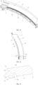
- the first light emergent surface 12 is preferably a curved surface protruding forwards, and may be configured as a single and smooth curved light emergent surface, hereby improving the aesthetics of the appearance of the vehicle lamp.
- the first cut-off portion 135 is located on the median surface of the first light emergent surface 12, and the median surface is a horizontal plane passing through the vertex of a longitudinal transversal of the first light emergent surface 12, such that the first light shape cut-off line correspondingly formed by the first cut-off portion 135 is clearer and realizes a better light shape.
- the first light emergent surface 12 is a curvature continuous curved surface, which improves the appearance and the light emerging effect of the first optical element 1.
- the at least one first light incident structure according to the present invention may be specifically configured to have at least one low-beam first light incident structure 111, or have at least one high-beam first light incident structure 112, or have at least one low-beam first light incident structure 111 and at least one high-beam first light incident structure 112. There may be one, two, three or more low-beam first light incident structures 111 and/or high-beam first light incident structures 112, and the number may be configured according to actual application requirements of the vehicle lamp optical unit.
- the projection plane shapes of the first light emergent surface 12 and the light incident structure reference plane 11 along the light emergent direction are respectively a strip-shape extending left and right;
- the first light incident structure is configured to be multiple low-beam first light incident structures 111 and multiple high-beam first light incident structures 112;
- the low-beam first light incident structures 111 and the high-beam first light incident structures 112 are arranged alternately;
- each of the collimators 113 is located on the lower side of the light incident structure reference plane 11.
- the first optical element 1 can be simultaneously used for forming partial light shape or complete light shape of the low beam or the high beam, and integrate multiple functions as a whole, thus making the structural design simple and compact.
- the alternate arrangement of the low-beam first light incident structures 111 and the high-beam first light incident structures 112 can meet the requirement that under the two modes, i.e., the low-beam mode and the high-beam mode, the first light emergent surface 12 has consistent lightening effect, and it is avoided that the first light emergent surface 12 is only partially lightened in a single low-beam mode, which affects the lightening effect of the vehicle lamp.
- the distance between the first cut-off portion 135 corresponding to the low-beam first light incident structure 111 and the upper surface of the first light passage 13 is greater than the distance between the first cut-off portion 135 corresponding to the high-beam first light incident structure 112 and the upper surface of the first light passage 13, that is to say, the first cut-off portion 135 corresponding to the high-beam first light incident structure 112 is higher than the first cut-off portion 135 corresponding to the low-beam first light incident structure 111, such that there is a segment difference the first cut-off portion 135 corresponding to the low-beam first light incident structure 111 and the first cut-off portion 135 corresponding to the high-beam first light incident structure 112.
- the high-beam light shape and the low-beam light shape have a certain superposition, that is to say, the cut-off line of the high-beam light shape is located below the cut-off line of the low-beam light shape, and accordingly, the adjoining effect between the low beam and the high beam is better.
- the intermediate connection surface 133 corresponding to the low-beam first light incident structure 111 is configured to tilt upwards from back to front, and the side of the intermediate connection surface 133 facing the first light passage 13 is configured as a reflecting surface; and the intermediate connection surface 133 corresponding to the high-beam first light incident structure 112 is configured to tilt downwards from back to front, and the side of the intermediate connection surface 133 departing from the first light passage 13 is also configured as a reflecting surface.
- light rays received by the low-beam first light incident structure 111 are subjected to a direction change by the light guide portion 114 and are emitted towards the first light passage 13, then most light rays are directly transmitted to the first light emergent surface 12 after passing through the first light passage 13 and being cut off by the corresponding first cut-off portion 135 thereof, while other minor light rays are directed to the corresponding intermediate connection surface 133 thereof and reflected by the intermediate connection surface 133 to the inside of the first light passage 13 for further transmission, so as to improve the luminous efficiency.
- Those two parts of light rays commonly form a light shape having an auxiliary low-beam cut-off line after emerging from the first light emergent surface 12. Referring to Fig.
- the high-beam first light incident structure 112 takes the corresponding light guide portion connection surface 132 as a primary high-beam light emergent surface and takes the light passage connection surface 134 as a secondary high-beam light incident surface. Light rays received by the high-beam first light incident structure 112 emerge from the corresponding light guide portion connection surface 132 after direction change by the light guide portion 114.
- Most light rays directly enter the first light passage 13 through the corresponding light passage connection surface 134 after being cut off by the corresponding first cut-off portion 135, and are transmitted to the first light emergent surface 12, while other minor light rays are directed to the corresponding intermediate connection surface 133 thereof and reflected by the intermediate connection surface 133 to the corresponding light passage connection surface 134 and are further transmitted in the first light passage 13, so as to improve the luminous efficiency.
- Those two parts of light rays commonly form a light shape having an auxiliary high-beam cut-off line after emerging from the first light emergent surface 12.
- this vehicle lamp optical unit further comprises a second optical element 2; a notch for accommodating the second optical element 2 is formed on one side in the left and right direction of the first optical element 1; the rear end face and the front end face of the second optical element 2 along the light emergent direction are respectively a light incident surface 21 and a second light emergent surface 22; the light incident surface 21 is provided with at least one second light incident structure; and the second optical element 2 is configured to be capable of guiding light rays emerging from the second light emergent surface 22 to exit through the first light emergent surface 12.
- the first optical element 1 and the second optical element 2 share the first light emergent surface 12, which is more conducive to the combination of the light shapes of the two, such that the vehicle lamp optical unit forms a desired vehicle lamp light shape.
- the first optical element 1 is preferably provided with a secondary light incident surface 14, the secondary light incident surface 14 is located in the rear of the first light emergent surface 12 and faces the notch, and the secondary light incident surface 14 comprises at least one curved surface protruding backwards.
- the light incident surface 21 is provided with multiple second light incident structures, and the multiple second light incident structures are configured to have at least one low-beam second light incident structure 211 and at least one high-beam second light incident structure 212.
- the specific numbers of the low-beam second light incident structures 211 and the high-beam second light incident structures 212 may be configured according to requirements for the light shape formed by the second optical element 2; moreover, it is preferred that those two are molded as a whole, hereby improving the installation accuracy of the vehicle lamp optical unit.
- each of the low-beam second light incident structures 211 and each of the high-beam second light incident structures 212 are respectively a collimating structure.
- the collimating structure may be a collimating element, such as a collimating cup, so as to improve the light efficiency.
- the low-beam second light incident structure 211 is located above the high-beam second light incident structure 212;
- the second light emergent surface 22 comprises a low-beam light emergent surface 221 located in front of the low-beam second light incident structure 211 and a high-beam light emergent surface 222 located at the light emergent end of the high-beam second light incident structure 212;
- a second light passage 23 is provided between the light emergent end of the low-beam second light incident structure 211 and the low-beam light emergent surface 221;
- a second cut-off portion 24 for forming a second light shape cut-off line is provided at the connection between the bottom surface of the second light passage 23 and the low-beam light emergent surface 221.
- the lower surface of the second light passage 23 is configured as a reflecting surface.
- the lower surface of the second light passage 23 is configured as a reflecting surface.
- the low-beam light emergent surface 221 is configured as a curved surface protruding forwards, and specifically may be a curved surface protruding in up-down direction, or may also be a curved surface protruding in left-right direction, or may also be a curved surface protruding simultaneously in up-down direction and in left-right direction.
- This structure makes light rays emerging from the low-beam light emergent surface 221 more concentrated, and more light rays would enter the secondary light incident surface 14, hereby further improving the luminous efficiency.
- a light guide 3 is further provided in the recess structure 131, and the light emergent surface of the light guide 3 faces towards the light passage connection surface 134, such that light rays emerging from the light emergent surface of the light guide 3 are transmitted to the first light emergent surface 12 through the first light passage 13.
- the light guide 3 shares the first light emergent surface 12 with the first optical element 1 and the second optical element 2, such that the vehicle lamp optical unit not only has the low-beam illumination function and/or the high-beam illumination function, but also has various illumination functions such as a low-beam III zone, a daytime running lamp or a position lamp, while occupied space is small.
- the minimum distance L between the two is set to ⁇ 10 mm, preferably, 1 mm ⁇ L ⁇ 5 mm; and when the first optical element 1 is only provided with a low-beam first light incident structure 111, the distance L may be set to 0.
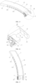
- the vehicle lamp optical unit comprises a first optical element 1 and a second optical element 2.
- the rear end face and the front end face of the first optical element 1 along a light emergent direction are respectively a light incident structure reference plane 11 and a first light emergent surface 12.
- the projection plane shapes of the first light emergent surface 12 and the light incident structure reference plane 11 along the light emergent direction are respectively a strip-shape extending left and right.
- the rear end of the first optical element 11 is formed as a light incident portion, the light incident portion comprises a first light incident structure provided along the left and right direction of the light incident structure reference plane 11.
- a first light passage 13 is formed between the light incident portion and the first light emergent surface 12.
- the first light emergent surface 12 is a curvature continuous curved surface protruding forwards.
- the first light incident structure is configured to have six low-beam first light incident structures 111 and four high-beam first light incident structures 112.
- the low-beam first light incident structures 111 and the high-beam first light incident structures 112 are arranged alternately.
- Each of the low-beam first light incident structures 111 and each of the high-beam first light incident structures 112 respectively comprises a collimator 113 located on the lower side of the light incident structure reference plane 11 and a light guide portion 114.
- the light guide portion 114 extends from the light emergent end of the collimator 113 to the rear end of the first light passage 13.
- the light guide portion 114 is provided with a reflecting portion 115, and the reflecting portion 115 can reflect the emergent light of the collimator 113 to a direction towards the first light passage 13 for emergence.
- a recess structure 131 corresponding to the light guide portion 114 is respectively provided at the connection between the first light passage 13 and each of the light guide portions 114.
- Each of the recess structures 131 respectively comprises a light guide portion connection surface 132 in connection with the light guide portion 114 corresponding to the recess structure 131, an intermediate connection surface 133 in connection with the light guide portion connection surface 132, and an light passage connection surface 134 in connection with the intermediate connection surface 133.
- a first cut-off portion 135 forming a first light shape cut-off line is provided at the connection between the intermediate connection surface 133 and the light passage connection surface 134, and the first cut-off portion 135 is located on the median surface of the first light emergent surface 12.
- the distance between the first cut-off portion 135 corresponding to the low-beam first light incident structure 111 and the upper surface of the first light passage 13 is greater than the distance between the first cut-off portion 135 corresponding to the high-beam first light incident structure 112 and the upper surface of the first light passage 13.
- the intermediate connection surface 133 corresponding to the low-beam first light incident structure 111 is configured to tilt upwards from back to front, and the side of the intermediate connection surface 133 facing the first light passage 13 is a reflecting surface.
- the intermediate connection surface 133 corresponding to the high-beam first light incident structure 112 is configured to tilt downwards from back to front, and the side of the intermediate connection surface 133 departing from the first light passage 13 is a reflecting surface.
- a notch for accommodating the second optical element 2 is formed on the right side in the left and right direction of the first optical element 1, a secondary light incident surface 14 is located in the rear of the first light emergent surface 12 and faces the notch, and the secondary light incident surface 14 comprises two curved surface protruding backwards, which are arranged in the left and right direction.
- the rear end face and the front end face of the second optical element 2 along the light emergent direction are respectively a light incident surface 21 and a second light emergent surface 22.
- the second light emergent surface 22 is arranged to face the secondary light incident surface 14.
- the light incident surface 21 is provided with two low-beam second light incident structures 211 and two high-beam second light incident structures 212.
- the low-beam second light incident structure 211 is located above the high-beam second light incident structure 212.
- the light emergent end of the high-beam second light incident structure 212 is configured as a high-beam light emergent surface 222.
- the front end of the low-beam second light incident structure 211 is successively provided with a second light passage 23 and a low-beam light emergent surface 221.
- a second cut-off portion 24 for forming a second light shape cut-off line is provided at the connection between the bottom surface of the second light passage 23 and the low-beam light emergent surface 221.
- the upper and lower sides of the lower surface of the second light passage 23 are both configured as reflecting surfaces.
- the low-beam light emergent surface 221 is configured as a curved surface protruding forwards.
- a light guide 3 for forming the light shape of a daytime running lamp may further be provided in the recess structure 131.
- the light emergent surface of the light guide 3 faces the light passage connection surface 134, and the minimum distance L between the light guide 3 and the intermediate connection surface 133 is set to 3 mm.
- the collimator 113 corresponding to the low-beam first light incident structure 111 receives light rays and emits the same to the light guide portion 114, the light rays are reflected by the reflecting portion 115 on the light guide portion 114 to the direction towards the first light passage 13 for emergence, and the light rays are transmitted to the first light emergent surface 12 through the first light passage 13 and form an auxiliary low-beam light shape b having an auxiliary low-beam cut-off line via the corresponding first cut-off portion 135 thereof; when turning on the light source 4 corresponding to the high-beam first light incident structure 112, the collimator 113 corresponding to the high-beam first light incident structure 112 receives light rays and emits the same to the light guide portion 114, the light rays emerge
- the vehicle lamp optical unit as described above can realize various illumination functions such as low beam, high beam, and daytime running lamp.
- light sources corresponding to the low-beam first light incident structure 111 and the low-beam second light incident structure 211 are turned on, it is the low-beam illumination mode for the vehicle lamp, and when the light sources corresponding to the high-beam first light incident structure 112 and the high-beam second light incident structure 212 are turned on, it is switched to the high beam illumination mode.
- the function of the daytime running lamp can be realized just by turning on the light source corresponding to the light guide 3.
- partial light shapes of the low beam or the high beam of the vehicle lamp are formed through projection by the first light emergent surface 12 of the first optical element 1.
- the respective partial light shapes form a complete low beam or high beam light shape by splicing.
- specific welcome or shutting-down mode of the vehicle lamp can be realized by lighting up the light sources 4 in a certain order when the vehicle lamp is lit up or shut down. For example, as shown in Figs. 31 and 32 , the low-beam light shape of the vehicle lamp is divided into nine areas.
- light sources 4 corresponding to the nine areas are lit up one by one from left to right, so as to form light shapes of the nine areas in order, which are shown as 1, 2, 3, 4, 5, 6, 7, 8 and 9, hereby realizing the welcome mode of the vehicle lamp and ultimately forming a complete low-beam light shape.
- a second aspect of the present invention provides a vehicle lamp module, comprising a vehicle lamp optical unit according to any one of the above-mentioned embodiments, and light sources 4 provided in one-to-one correspondence with the first light incident structures, wherein each of the light sources 4 is capable of being controlled individually to be turned on or turned off. Therefore, it at least has all the beneficial effects brought by the technical solutions of the above-mentioned embodiments of the vehicle lamp optical unit.
- a third aspect of the present invention provides a vehicle, comprising a vehicle lamp module as described above. Therefore, it at least has all the beneficial effects brought by the technical solutions of the above-mentioned embodiments of the vehicle lamp optical unit and the vehicle lamp module.
- the first light incident structure is configured to extend from one side in the upper-lower width direction of the light incident structure reference plane 11 to the first light passage 13, the first light incident structure can guide light rays received thereby to be emitted towards the first light passage 13 and be transmitted to the first light emergent surface 12 along the first light passage 13, that is to say, a light source corresponding to the first light incident structure is provided on the upper side or the lower side of the light incident structure reference plane 11, wherein it can be effectively avoided that a light spot is produced in a situation where the light source 4 is provided in the rear of the first optical element 1, hereby improving the illumination visual effect of the vehicle lamp optical unit; moreover, the vehicle lamp optical unit can meet requirements for various vehicle lamp illumination modes and lightening modes.
Landscapes
- Engineering & Computer Science (AREA)
- General Engineering & Computer Science (AREA)
- Physics & Mathematics (AREA)
- Microelectronics & Electronic Packaging (AREA)
- Optics & Photonics (AREA)
- Non-Portable Lighting Devices Or Systems Thereof (AREA)
Claims (13)
- Eine optische Einheit für Fahrzeuglampen, die ein erstes optisches Element (1) aufweist, bei der eine hintere Endfläche und eine vordere Endfläche des ersten optischen Elements (1) entlang einer Lichtaustritts-Richtung jeweils eine Referenzebene (11) für eine Lichteinfalls-Struktur bzw. eine erste Lichtaustritts-Oberfläche (12) sind, wobei ein hinteres Ende des ersten optischen Elements (1) als ein Lichteinfalls-Teil gebildet ist, wobei der Lichteinfalls-Teil mindestens eine erste Lichteinfalls-Struktur aufweist, die entlang der linken und rechten Richtung der Referenzebene (11) für die Lichteinfalls-Struktur zur Verfügung gestellt ist, und wobei ein erster Lichtdurchgang (13) zwischen dem Lichteinfalls-Teil und der ersten Lichtaustritts-Oberfläche (12) gebildet ist,wobei die erste Lichteinfalls-Struktur dafür konfiguriert ist, dass sie sich ausgehend von einer oberen Seite oder einer unteren Seite der Referenzebene (11) für die Lichteinfalls-Struktur bis zu dem ersten Lichtdurchgang (13) hin erstreckt, wobei jede der ersten Lichteinfalls-Strukturen in der Lage ist, Lichtstrahlen, die von der ersten Lichteinfalls-Struktur empfangen worden sind, so zu leiten, dass sie in Richtung des ersten Lichtdurchgangs (13) emittiert werden und entlang des ersten Lichtdurchgangs (13) zu der ersten Lichtaustritts-Oberfläche (12) hin transmittiert werden,dadurch gekennzeichnet, dass die optische Einheit für Fahrzeuglampen des Weiteren ein zweites optisches Element (2) aufweist; wobei eine Kerbe für die Aufnahme des zweiten optischen Elements (2) auf einer Seite in der linken und rechten Richtung des ersten optischen Elements (1) gebildet ist; wobei die hintere Endfläche und die vordere Endfläche des zweiten optischen Elements (2) entlang der Lichtaustritts-Richtung jeweils eine Lichteinfalls-Oberfläche (21) bzw. eine zweite Lichtaustritts-Oberfläche (22) sind; wobei die Lichteinfalls-Oberfläche (21) mit mindestens einer zweiten Lichteinfalls-Struktur versehen ist; undwobei das erste optische Element (1) mit einer sekundären Lichteinfalls-Oberfläche (14) versehen ist, wobei die sekundäre Lichteinfalls-Oberfläche (14) auf der Rückseite der ersten Lichtaustritts-Oberfläche (12) angeordnet ist und zu der Kerbe hin ausgerichtet ist, undwobei die sekundäre Lichteinfalls-Oberfläche (14) mindestens eine gekrümmte Oberfläche aufweist, die nach hinten vorsteht, und wobei das zweite optische Element (12) dafür konfiguriert ist, dass es in der Lage ist, Lichtstrahlen, die von der zweiten Lichtaustritts-Oberfläche (22) austreten, so zu leiten, dass sie durch die erste Lichtaustritts-Oberfläche (12) austreten, nachdem sie von der sekundären Lichteinfalls-Oberfläche (14) eingefallen sind.
- Die optische Einheit für Fahrzeuglampen gemäß dem Anspruch 1, bei der jede der ersten Lichteinfalls-Strukturen jeweils einen Kollimator (113), der sich auf der oberen Seite oder der unteren Seite der Referenzebene (11) für die Lichteinfalls-Struktur befindet, und einen Lichtleiter-Teil (114) aufweist, der mit dem Kollimator (113) in Verbindung steht; wobei sich der Lichtleiter-Teil (114) ausgehend von einem Lichtaustritts-Ende des Kollimators (113) bis zu einem hinteren Ende des ersten Lichtdurchgangs (13) hin erstreckt; wobei der Lichtleiter-Teil (114) mit einem reflektierenden Teil (115) versehen ist; und wobei der reflektierende Teil (115) in der Lage ist, ein austretendes Licht des Kollimators (113) in eine Richtung zu dem ersten Lichtdurchgang (13) hin für ein Austreten zu reflektieren.
- Die optische Einheit für Fahrzeuglampen gemäß dem Anspruch 2, bei der eine Ausnehmungs-Struktur (131), die mit dem Lichleiter-Teil (114) korrespondiert, an einer Verbindung zwischen dem ersten Lichtdurchgang (13) und jedem der Lichleiter-Teile (114) jeweils zur Verfügung gestellt ist, und wobei jede der Ausnehmungs-Strukturen (131) jeweils eine Lichleiter-Teil-Verbindungs-Oberfläche (132), die mit dem Lichleiter-Teil (114), der mit der Ausnehmungs-Struktur (131) korrespondiert, in Verbindung steht, aufweist, eine Zwischen-Verbindungs-Oberfläche (133), die mit der Lichleiter-Teil-Verbindungs-Oberfläche (132) in Verbindung steht, aufweist und eine Lichtdurchgangs-Verbindungs-Oberfläche (134), die mit der Zwischen-Verbindungs-Oberfläche (133) in Verbindung steht, aufweist,
wobei ein erster Abschneide-Teil (135), der eine erste Licht-Form-Abschneide-Linie bildet, an einer Verbindung zwischen der Zwischen-Verbindungs-Oberfläche (133) und der Lichtdurchgangs-Verbindungs-Oberfläche (134) zur Verfügung gestellt ist. - Die optische Einheit für Fahrzeuglampen gemäß dem Anspruch 3, bei der die erste Lichtaustritts-Oberfläche (12) eine gekrümmte Oberfläche ist, die nach vorne vorsteht, wobei der erste Abschneide-Teil (135) sich auf einer Median-Oberfläche der ersten Lichtaustritts-Oberfläche (12) befindet, und wobei die Median-Oberfläche eine horizontale Ebene ist, die durch einen Scheitelpunkt einer in Längsrichtung verlaufenden Transversale der ersten Lichtaustritts-Oberfläche (12) verläuft.
- Die optische Einheit für Fahrzeuglampen gemäß dem Anspruch 4, bei der die erste Lichtaustritts-Oberfläche (12) eine Krümmung oder eine kontinuierlich gekrümmte Oberfläche ist.
- Die optische Einheit für Fahrzeuglampen gemäß dem Anspruch 3, bei der ein Lichtleiter (3) in der Ausnehmungs-Struktur (131) vorgesehen ist, und wobei eine Lichtaustritts-Oberfläche des Lichtleiters (3) zu der Lichtdurchgangs-Verbindungs-Oberfläche (134) hin so ausgerichtet ist, dass Lichtstrahlen, die aus der Lichtaustritts-Oberfläche des Lichtleiters (3) ausgetreten sind, durch den ersten Lichtdurchgang (13) hindurch zu der ersten Lichtaustritts-Oberfläche (12) hin transmittiert werden.
- Die optische Einheit für Fahrzeuglampen gemäß dem Anspruch 3, bei der die mindestens eine erste Lichteinfalls-Struktur dafür konfiguriert ist, dass sie mindestens eine erste Lichteinfalls-Struktur für Abblendlicht (111) aufweist oder dass sie mindestens eine erste Lichteinfalls-Struktur für Fernlicht (112) aufweist oder dass sie mindestens eine erste Lichteinfalls-Struktur für Abblendlicht (111) und mindestens eine erste Lichteinfalls-Struktur für Fernlicht (112) aufweist; wobei es bevorzugt ist, dass die Zwischen-Verbindungs-Oberfläche (133), die mit der ersten Lichteinfalls-Struktur (111) für Abblendlicht korrespondiert, dafür konfiguriert ist, dass sie sich dann von hinten nach vorne nach oben neigt, wenn die optische Einheit für Lampen in einem Fahrzeug montiert ist, und dass eine Seite der Zwischen-Verbindungs-Oberfläche (133), die zu dem ersten Lichtdurchgang (13) hin ausgerichtet ist, eine reflektierende Oberfläche ist; und wobei es bevorzugt ist, dass die Zwischen-Verbindungs-Oberfläche (133), die mit der ersten Lichteinfalls-Struktur (112) für Fernlicht korrespondiert, dafür konfiguriert ist, dass sie sich dann von hinten nach vorne nach unten neigt, wenn die optische Einheit für Lampen in einem Fahrzeug montiert ist, und dass eine Seite der Zwischen-Verbindungs-Oberfläche (133), die von dem ersten Lichtdurchgang (13) wegführt, eine reflektierende Oberfläche ist.
- Die optische Einheit für Fahrzeuglampen gemäß dem Anspruch 7, bei der Formen von Vorsprüngen der ersten Lichtaustritts-Oberfläche (12) und der Referenzebene (11) für die Lichteinfalls-Struktur entlang der Lichtaustritts-Richtung jeweils eine Streifenform sind, die sich nach links und rechts erstreckt; wobei die erste Lichteinfalls-Struktur als eine Vielzahl von den ersten Lichteinfalls-Strukturen (111) für Abblendlicht und eine Vielzahl von den ersten Lichteinfalls-Strukturen (112) für Fernlicht zur Verfügung gestellt ist; wobei die ersten Lichteinfalls-Strukturen (111) für Abblendlicht und die ersten Lichteinfalls-Strukturen (112) für Fernlicht abwechselnd angeordnet sind; und wobei jeder der Kollimatoren (113) an der unteren Seite der Referenzebene für die Lichteinfalls-Struktur (11) angeordnet ist.
- Die optische Einheit für Fahrzeuglampen gemäß dem Anspruch 8, bei der eine Distanz zwischen dem ersten Abschneide-Teil (135), der mit der ersten Lichteinfalls-Struktur (111) für Abblendlicht korrespondiert, und einer oberen Oberfläche des ersten Lichtdurchgangs (13) größer ist als eine Distanz zwischen dem ersten Abschneide-Teil (135), der mit der ersten Lichteinfalls-Struktur (112) für Fernlicht korrespondiert, und der oberen Oberfläche des ersten Lichtdurchgangs (13).
- Die optische Einheit für Fahrzeuglampen gemäß irgend einem der Ansprüche Anspruch 1 bis 9, bei der die Lichteinfalls-Oberfläche (21) mit einer Vielzahl von den zweiten Lichteinfalls-Strukturen versehen ist, und wobei die Vielzahl von den zweiten Lichteinfalls-Strukturen dafür konfiguriert sind, dass sie mindestens eine zweite Lichteinfalls-Struktur (211) für Abblendlicht und mindestens eine zweite Lichteinfalls-Struktur (212) für Fernlicht aufweisen; wobei es bevorzugt ist, dass jede der zweiten Lichteinfalls-Strukturen (211) für Abblendlicht und jede der zweiten Lichteinfalls-Strukturen (212) für Fernlicht jeweils eine Kollimator-Struktur ist.
- Die optische Einheit für Fahrzeuglampen gemäß dem Anspruch 10, bei der die zweite Lichteinfalls-Struktur (211) für Abblendlicht über der zweiten Lichteinfalls-Struktur (212) für Fernlicht angeordnet ist; wobei die zweite Lichtaustritts-Oberfläche (22) eine Lichtaustritts-Oberfläche (221) für Abblendlicht aufweist, die vor der zweiten Lichteinfalls-Struktur (211) für Abblendlicht angeordnet ist, und eine Lichtaustritts-Oberfläche (222) für Fernlicht aufweist, die an einem Lichtaustritts-Ende der zweiten Lichteinfalls-Struktur (212) für Fernlicht angeordnet ist; wobei ein zweiter Lichtdurchgang (23) zwischen dem Lichtaustritts-Ende der zweiten Lichteinfalls-Struktur (211) für Abblendlicht und der Lichtaustritts-Oberfläche (221) für Abblendlicht zur Verfügung gestellt ist; und wobei ein zweiter Abschneide-Teil (24) für die Bildung einer zweiten Licht-Form-Abschneide-Linie an einer Verbindung zwischen einer unteren Oberfläche des zweiten Lichtdurchgangs (23) und der Lichtaustritts-Oberfläche (221) für das Abblendlicht vorgesehen ist; wobei es bevorzugt ist, dass eine untere Oberfläche des zweiten Lichtdurchgangs (23) als eine reflektierende Oberfläche vorgesehen ist; und wobei es bevorzugt ist, dass die Lichtaustritts-Oberfläche (211) für Abblendlicht als eine gekrümmte Oberfläche, die nach vorne vorspringt, zur Verfügung gestellt ist.
- Ein Fahrzeuglampenmodul, dadurch gekennzeichnet, dass das Fahrzeuglampenmodul die optische Einheit für Fahrzeuglampen gemäß irgend einem der Ansprüche 1 bis 11 sowie Lichtquellen (4) umfasst, die in einer Eins-zu-eins-Entsprechung mit den ersten Lichteinfalls-Strukturen zur Verfügung gestellt sind, wobei jede der Lichtquellen (4) in der Lage ist, dass sie individuell gesteuert wird, um ein- oder ausgeschaltet zu werden.
- Ein Fahrzeug, dadurch gekennzeichnet, dass das Fahrzeug das Fahrzeuglampenmodul gemäß dem Anspruch 12 umfasst.
Applications Claiming Priority (2)
| Application Number | Priority Date | Filing Date | Title |
|---|---|---|---|
| CN202010634007.4A CN113883469B (zh) | 2020-07-02 | 2020-07-02 | 车灯光学单元、车灯模组和车辆 |
| PCT/CN2021/071523 WO2022001087A1 (zh) | 2020-07-02 | 2021-01-13 | 车灯光学单元、车灯模组和车辆 |
Publications (4)
| Publication Number | Publication Date |
|---|---|
| EP4137744A1 EP4137744A1 (de) | 2023-02-22 |
| EP4137744A4 EP4137744A4 (de) | 2023-09-13 |
| EP4137744C0 EP4137744C0 (de) | 2025-01-08 |
| EP4137744B1 true EP4137744B1 (de) | 2025-01-08 |
Family
ID=79012743
Family Applications (1)
| Application Number | Title | Priority Date | Filing Date |
|---|---|---|---|
| EP21832556.1A Active EP4137744B1 (de) | 2020-07-02 | 2021-01-13 | Optische einheit für fahrzeuglampe, fahrzeuglampenmodul und fahrzeug |
Country Status (3)
| Country | Link |
|---|---|
| EP (1) | EP4137744B1 (de) |
| CN (1) | CN113883469B (de) |
| WO (1) | WO2022001087A1 (de) |
Families Citing this family (4)
| Publication number | Priority date | Publication date | Assignee | Title |
|---|---|---|---|---|
| EP4170228A1 (de) * | 2021-10-22 | 2023-04-26 | ZKW Group GmbH | Beleuchtungsvorrichtung für fahrzeugscheinwerfer |
| CN116379374A (zh) * | 2023-03-16 | 2023-07-04 | 马瑞利汽车零部件(芜湖)有限公司 | 双功能模组及车灯系统 |
| EP4462014A1 (de) * | 2023-05-12 | 2024-11-13 | ZKW Group GmbH | Beleuchtungsvorrichtung für einen kraftfahrzeugscheinwerfer sowie kraftfahrzeugscheinwerfer |
| US20250264201A1 (en) * | 2024-02-15 | 2025-08-21 | Tyri International Inc. | Vehicle Headlamp for High Mount Applications |
Family Cites Families (24)
| Publication number | Priority date | Publication date | Assignee | Title |
|---|---|---|---|---|
| US7677777B2 (en) * | 2007-02-21 | 2010-03-16 | Magna International, Inc. | LED apparatus for world homologation |
| FR3038696B1 (fr) * | 2015-07-10 | 2022-02-18 | Valeo Vision | Module lumineux pour l'eclairage et/ou la signalisation d'un vehicule automobile |
| FR3041071B1 (fr) * | 2015-09-14 | 2020-02-07 | Valeo Vision | Module lumineux en materiau transparent |
| US9809150B2 (en) * | 2015-10-28 | 2017-11-07 | GM Global Technology Operations LLC | Headlamp assembly |
| FR3055400B1 (fr) * | 2016-09-01 | 2019-06-28 | Valeo Vision | Module optique pour eclairer des points de portique |
| FR3056688B1 (fr) * | 2016-09-26 | 2018-11-02 | Valeo Vision | Module d'eclairage bi-fonction en materiau transparent |
| DE102016125887A1 (de) * | 2016-12-29 | 2018-07-05 | Automotive Lighting Reutlingen Gmbh | Lichtmodul für Kraftfahrzeugscheinwerfer |
| CN206892528U (zh) * | 2017-05-03 | 2018-01-16 | 深圳市希尔光学技术有限公司 | 一种用于道路监控的补光灯 |
| KR102439168B1 (ko) * | 2017-12-29 | 2022-09-01 | 에스엘 주식회사 | 차량용 램프 |
| FR3086734B1 (fr) * | 2018-09-28 | 2022-06-24 | Valeo Vision | Module lumineux de vehicule comprenant un pion de referencement avec une partie souple et une partie rigide |
| DE102018125157A1 (de) * | 2018-10-11 | 2020-04-16 | HELLA GmbH & Co. KGaA | Scheinwerfer für Fahrzeuge |
| FR3087395B1 (fr) * | 2018-10-22 | 2021-02-26 | Psa Automobiles Sa | Dispositif d’eclairage avant pour vehicule automobile |
| TWI662224B (zh) * | 2018-12-26 | 2019-06-11 | 聯嘉光電股份有限公司 | Led車載線形發光模組 |
| CN110067986A (zh) * | 2019-06-03 | 2019-07-30 | 华域视觉科技(上海)有限公司 | 近光反射镜、远近光一体的投射式前照灯单元及车辆 |
| CN209944214U (zh) * | 2019-07-09 | 2020-01-14 | 南京缤致光电科技有限公司 | 一种远近光一体聚光器 |
| CN210568140U (zh) * | 2019-07-11 | 2020-05-19 | 浙江百康光学股份有限公司 | 双光透镜模组、汽车大灯以及车辆 |
| CN210141552U (zh) * | 2019-07-19 | 2020-03-13 | 华域视觉科技(上海)有限公司 | 初级光学元件、车灯模组、车灯及车辆 |
| CN210568141U (zh) * | 2019-08-15 | 2020-05-19 | 华域视觉科技(上海)有限公司 | 一种远近光一体的车灯模组、车灯和车辆 |
| CN210345321U (zh) * | 2019-09-20 | 2020-04-17 | 华域视觉科技(上海)有限公司 | 车灯光学元件、车灯模组、车灯及车辆 |
| CN210398742U (zh) * | 2019-10-22 | 2020-04-24 | 华域视觉科技(上海)有限公司 | 一种双光车灯照明装置及车灯 |
| CN210601445U (zh) * | 2019-10-25 | 2020-05-22 | 华域视觉科技(上海)有限公司 | 一种车灯光学元件 |
| CN210662681U (zh) * | 2019-10-30 | 2020-06-02 | 上汽通用五菱汽车股份有限公司 | 一种厚壁光导配光系统 |
| CN211822197U (zh) * | 2020-01-21 | 2020-10-30 | 华域视觉科技(上海)有限公司 | 前照灯模组、前照灯及车辆 |
| CN212618081U (zh) * | 2020-07-02 | 2021-02-26 | 华域视觉科技(上海)有限公司 | 车灯光学单元、车灯模组和车辆 |
-
2020
- 2020-07-02 CN CN202010634007.4A patent/CN113883469B/zh active Active
-
2021
- 2021-01-13 EP EP21832556.1A patent/EP4137744B1/de active Active
- 2021-01-13 WO PCT/CN2021/071523 patent/WO2022001087A1/zh not_active Ceased
Also Published As
| Publication number | Publication date |
|---|---|
| CN113883469B (zh) | 2025-12-19 |
| EP4137744A1 (de) | 2023-02-22 |
| EP4137744C0 (de) | 2025-01-08 |
| WO2022001087A1 (zh) | 2022-01-06 |
| EP4137744A4 (de) | 2023-09-13 |
| CN113883469A (zh) | 2022-01-04 |
Similar Documents
| Publication | Publication Date | Title |
|---|---|---|
| EP4137744B1 (de) | Optische einheit für fahrzeuglampe, fahrzeuglampenmodul und fahrzeug | |
| EP2693105B1 (de) | Fahrzeugbeleuchtungseinheit | |
| US8480266B2 (en) | Vehicle light unit and vehicle light | |
| EP2479486B1 (de) | Fahrzeugsbeleuchtungseinheit | |
| JP5945857B2 (ja) | 車両用前照灯及び導光レンズ | |
| JP5563209B2 (ja) | 灯具 | |
| EP1970616A1 (de) | Fahrzeuglampe | |
| CN112752925A (zh) | 车灯光学元件、车灯模组、车辆前照灯及车辆 | |
| JP2005158362A (ja) | 車両用灯具 | |
| JP3216009U (ja) | 車両用の導光式死角領域・車線変更警告灯 | |
| US20140177255A1 (en) | Light conductor with a ribbon-shaped light emitting area | |
| EP2503224B1 (de) | Fahrzeugbeleuchtungseinheit | |
| WO2020232826A1 (zh) | 车灯用光学装置、汽车照明装置及汽车 | |
| JP7265437B2 (ja) | 車両用灯具 | |
| CN212618081U (zh) | 车灯光学单元、车灯模组和车辆 | |
| EP3988836B1 (de) | Optisches element, fahrzeuglampenmodul, fahrzeuglampe und fahrzeug | |
| CN210740255U (zh) | 一种车灯光学元件、车灯模组、车辆前照灯和车辆 | |
| CN208901313U (zh) | 配光构件、照明装置、信号指示装置和机动车辆 | |
| JP7557337B2 (ja) | 車両用灯具 | |
| WO2023126276A1 (en) | Light guide for a lighting device of a motor vehicle, lighting device and motor vehicle | |
| JP2023000113A (ja) | 車両用灯具 | |
| CN223550313U (zh) | 一种提升点亮均匀性的导光结构、车灯及车辆 | |
| CN221570334U (zh) | 一种集成式车灯近光照明元件及车辆 | |
| US12510220B2 (en) | Optical element, vehicle light module, vehicle light and vehicle | |
| CN222210033U (zh) | 一种反射式光学系统 |
Legal Events
| Date | Code | Title | Description |
|---|---|---|---|
| STAA | Information on the status of an ep patent application or granted ep patent |
Free format text: STATUS: THE INTERNATIONAL PUBLICATION HAS BEEN MADE |
|
| PUAI | Public reference made under article 153(3) epc to a published international application that has entered the european phase |
Free format text: ORIGINAL CODE: 0009012 |
|
| STAA | Information on the status of an ep patent application or granted ep patent |
Free format text: STATUS: REQUEST FOR EXAMINATION WAS MADE |
|
| 17P | Request for examination filed |
Effective date: 20221117 |
|
| AK | Designated contracting states |
Kind code of ref document: A1 Designated state(s): AL AT BE BG CH CY CZ DE DK EE ES FI FR GB GR HR HU IE IS IT LI LT LU LV MC MK MT NL NO PL PT RO RS SE SI SK SM TR |
|
| STAA | Information on the status of an ep patent application or granted ep patent |
Free format text: STATUS: EXAMINATION IS IN PROGRESS |
|
| A4 | Supplementary search report drawn up and despatched |
Effective date: 20230811 |
|
| RIC1 | Information provided on ipc code assigned before grant |
Ipc: F21S 41/151 20180101ALI20230807BHEP Ipc: F21S 41/663 20180101ALI20230807BHEP Ipc: F21S 41/40 20180101ALI20230807BHEP Ipc: F21S 41/27 20180101ALI20230807BHEP Ipc: F21S 41/265 20180101ALI20230807BHEP Ipc: F21S 41/147 20180101ALI20230807BHEP Ipc: F21W 102/00 20180101ALI20230807BHEP Ipc: F21S 41/24 20180101AFI20230807BHEP |
|
| 17Q | First examination report despatched |
Effective date: 20230823 |
|
| DAV | Request for validation of the european patent (deleted) | ||
| DAX | Request for extension of the european patent (deleted) | ||
| RIC1 | Information provided on ipc code assigned before grant |
Ipc: F21S 41/151 20180101ALI20240725BHEP Ipc: F21S 41/663 20180101ALI20240725BHEP Ipc: F21S 41/40 20180101ALI20240725BHEP Ipc: F21S 41/27 20180101ALI20240725BHEP Ipc: F21S 41/265 20180101ALI20240725BHEP Ipc: F21S 41/147 20180101ALI20240725BHEP Ipc: F21W 102/00 20180101ALI20240725BHEP Ipc: F21S 41/24 20180101AFI20240725BHEP |
|
| GRAP | Despatch of communication of intention to grant a patent |
Free format text: ORIGINAL CODE: EPIDOSNIGR1 |
|
| STAA | Information on the status of an ep patent application or granted ep patent |
Free format text: STATUS: GRANT OF PATENT IS INTENDED |
|
| INTG | Intention to grant announced |
Effective date: 20240902 |
|
| GRAS | Grant fee paid |
Free format text: ORIGINAL CODE: EPIDOSNIGR3 |
|
| GRAA | (expected) grant |
Free format text: ORIGINAL CODE: 0009210 |
|
| STAA | Information on the status of an ep patent application or granted ep patent |
Free format text: STATUS: THE PATENT HAS BEEN GRANTED |
|
| AK | Designated contracting states |
Kind code of ref document: B1 Designated state(s): AL AT BE BG CH CY CZ DE DK EE ES FI FR GB GR HR HU IE IS IT LI LT LU LV MC MK MT NL NO PL PT RO RS SE SI SK SM TR |
|
| REG | Reference to a national code |
Ref country code: GB Ref legal event code: FG4D |
|
| REG | Reference to a national code |
Ref country code: CH Ref legal event code: EP |
|
| REG | Reference to a national code |
Ref country code: DE Ref legal event code: R096 Ref document number: 602021024792 Country of ref document: DE |
|
| REG | Reference to a national code |
Ref country code: IE Ref legal event code: FG4D |
|
| U01 | Request for unitary effect filed |
Effective date: 20250113 |
|
| U07 | Unitary effect registered |
Designated state(s): AT BE BG DE DK EE FI FR IT LT LU LV MT NL PT RO SE SI Effective date: 20250117 |
|
| U20 | Renewal fee for the european patent with unitary effect paid |
Year of fee payment: 5 Effective date: 20250411 |
|
| PG25 | Lapsed in a contracting state [announced via postgrant information from national office to epo] |
Ref country code: RS Free format text: LAPSE BECAUSE OF FAILURE TO SUBMIT A TRANSLATION OF THE DESCRIPTION OR TO PAY THE FEE WITHIN THE PRESCRIBED TIME-LIMIT Effective date: 20250408 |
|
| PG25 | Lapsed in a contracting state [announced via postgrant information from national office to epo] |
Ref country code: PL Free format text: LAPSE BECAUSE OF FAILURE TO SUBMIT A TRANSLATION OF THE DESCRIPTION OR TO PAY THE FEE WITHIN THE PRESCRIBED TIME-LIMIT Effective date: 20250108 |
|
| PG25 | Lapsed in a contracting state [announced via postgrant information from national office to epo] |
Ref country code: ES Free format text: LAPSE BECAUSE OF FAILURE TO SUBMIT A TRANSLATION OF THE DESCRIPTION OR TO PAY THE FEE WITHIN THE PRESCRIBED TIME-LIMIT Effective date: 20250108 |
|
| PG25 | Lapsed in a contracting state [announced via postgrant information from national office to epo] |
Ref country code: NO Free format text: LAPSE BECAUSE OF FAILURE TO SUBMIT A TRANSLATION OF THE DESCRIPTION OR TO PAY THE FEE WITHIN THE PRESCRIBED TIME-LIMIT Effective date: 20250408 Ref country code: IS Free format text: LAPSE BECAUSE OF FAILURE TO SUBMIT A TRANSLATION OF THE DESCRIPTION OR TO PAY THE FEE WITHIN THE PRESCRIBED TIME-LIMIT Effective date: 20250508 |
|
| PG25 | Lapsed in a contracting state [announced via postgrant information from national office to epo] |
Ref country code: HR Free format text: LAPSE BECAUSE OF FAILURE TO SUBMIT A TRANSLATION OF THE DESCRIPTION OR TO PAY THE FEE WITHIN THE PRESCRIBED TIME-LIMIT Effective date: 20250108 |
|
| PG25 | Lapsed in a contracting state [announced via postgrant information from national office to epo] |
Ref country code: GR Free format text: LAPSE BECAUSE OF FAILURE TO SUBMIT A TRANSLATION OF THE DESCRIPTION OR TO PAY THE FEE WITHIN THE PRESCRIBED TIME-LIMIT Effective date: 20250409 |
|
| REG | Reference to a national code |
Ref country code: CH Ref legal event code: PL |
|
| PG25 | Lapsed in a contracting state [announced via postgrant information from national office to epo] |
Ref country code: SM Free format text: LAPSE BECAUSE OF FAILURE TO SUBMIT A TRANSLATION OF THE DESCRIPTION OR TO PAY THE FEE WITHIN THE PRESCRIBED TIME-LIMIT Effective date: 20250108 |
|
| PG25 | Lapsed in a contracting state [announced via postgrant information from national office to epo] |
Ref country code: MC Free format text: LAPSE BECAUSE OF FAILURE TO SUBMIT A TRANSLATION OF THE DESCRIPTION OR TO PAY THE FEE WITHIN THE PRESCRIBED TIME-LIMIT Effective date: 20250108 |
|
| PG25 | Lapsed in a contracting state [announced via postgrant information from national office to epo] |
Ref country code: CH Free format text: LAPSE BECAUSE OF NON-PAYMENT OF DUE FEES Effective date: 20250131 |
|
| PG25 | Lapsed in a contracting state [announced via postgrant information from national office to epo] |
Ref country code: CZ Free format text: LAPSE BECAUSE OF FAILURE TO SUBMIT A TRANSLATION OF THE DESCRIPTION OR TO PAY THE FEE WITHIN THE PRESCRIBED TIME-LIMIT Effective date: 20250108 |
|
| PG25 | Lapsed in a contracting state [announced via postgrant information from national office to epo] |
Ref country code: SK Free format text: LAPSE BECAUSE OF FAILURE TO SUBMIT A TRANSLATION OF THE DESCRIPTION OR TO PAY THE FEE WITHIN THE PRESCRIBED TIME-LIMIT Effective date: 20250108 |
|
| PLBE | No opposition filed within time limit |
Free format text: ORIGINAL CODE: 0009261 |
|
| STAA | Information on the status of an ep patent application or granted ep patent |
Free format text: STATUS: NO OPPOSITION FILED WITHIN TIME LIMIT |
|
| 26N | No opposition filed |
Effective date: 20251009 |
|
| GBPC | Gb: european patent ceased through non-payment of renewal fee |
Effective date: 20250408 |
|
| PG25 | Lapsed in a contracting state [announced via postgrant information from national office to epo] |
Ref country code: GB Free format text: LAPSE BECAUSE OF NON-PAYMENT OF DUE FEES Effective date: 20250408 |
|
| PG25 | Lapsed in a contracting state [announced via postgrant information from national office to epo] |
Ref country code: IE Free format text: LAPSE BECAUSE OF NON-PAYMENT OF DUE FEES Effective date: 20250113 |
|
| U20 | Renewal fee for the european patent with unitary effect paid |
Year of fee payment: 6 Effective date: 20260107 |