EP2479486B1 - Fahrzeugsbeleuchtungseinheit - Google Patents
Fahrzeugsbeleuchtungseinheit Download PDFInfo
- Publication number
- EP2479486B1 EP2479486B1 EP12000429.6A EP12000429A EP2479486B1 EP 2479486 B1 EP2479486 B1 EP 2479486B1 EP 12000429 A EP12000429 A EP 12000429A EP 2479486 B1 EP2479486 B1 EP 2479486B1
- Authority
- EP
- European Patent Office
- Prior art keywords
- light
- ray
- lens body
- lens
- total reflection
- Prior art date
- Legal status (The legal status is an assumption and is not a legal conclusion. Google has not performed a legal analysis and makes no representation as to the accuracy of the status listed.)
- Active
Links
Images


Classifications
-
- F—MECHANICAL ENGINEERING; LIGHTING; HEATING; WEAPONS; BLASTING
- F21—LIGHTING
- F21S—NON-PORTABLE LIGHTING DEVICES; SYSTEMS THEREOF; VEHICLE LIGHTING DEVICES SPECIALLY ADAPTED FOR VEHICLE EXTERIORS
- F21S43/00—Signalling devices specially adapted for vehicle exteriors, e.g. brake lamps, direction indicator lights or reversing lights
- F21S43/30—Signalling devices specially adapted for vehicle exteriors, e.g. brake lamps, direction indicator lights or reversing lights characterised by reflectors
- F21S43/31—Optical layout thereof
- F21S43/315—Optical layout thereof using total internal reflection
-
- F—MECHANICAL ENGINEERING; LIGHTING; HEATING; WEAPONS; BLASTING
- F21—LIGHTING
- F21S—NON-PORTABLE LIGHTING DEVICES; SYSTEMS THEREOF; VEHICLE LIGHTING DEVICES SPECIALLY ADAPTED FOR VEHICLE EXTERIORS
- F21S41/00—Illuminating devices specially adapted for vehicle exteriors, e.g. headlamps
- F21S41/20—Illuminating devices specially adapted for vehicle exteriors, e.g. headlamps characterised by refractors, transparent cover plates, light guides or filters
- F21S41/24—Light guides
-
- F—MECHANICAL ENGINEERING; LIGHTING; HEATING; WEAPONS; BLASTING
- F21—LIGHTING
- F21S—NON-PORTABLE LIGHTING DEVICES; SYSTEMS THEREOF; VEHICLE LIGHTING DEVICES SPECIALLY ADAPTED FOR VEHICLE EXTERIORS
- F21S41/00—Illuminating devices specially adapted for vehicle exteriors, e.g. headlamps
- F21S41/30—Illuminating devices specially adapted for vehicle exteriors, e.g. headlamps characterised by reflectors
- F21S41/32—Optical layout thereof
- F21S41/322—Optical layout thereof the reflector using total internal reflection
-
- F—MECHANICAL ENGINEERING; LIGHTING; HEATING; WEAPONS; BLASTING
- F21—LIGHTING
- F21S—NON-PORTABLE LIGHTING DEVICES; SYSTEMS THEREOF; VEHICLE LIGHTING DEVICES SPECIALLY ADAPTED FOR VEHICLE EXTERIORS
- F21S43/00—Signalling devices specially adapted for vehicle exteriors, e.g. brake lamps, direction indicator lights or reversing lights
- F21S43/10—Signalling devices specially adapted for vehicle exteriors, e.g. brake lamps, direction indicator lights or reversing lights characterised by the light source
- F21S43/13—Signalling devices specially adapted for vehicle exteriors, e.g. brake lamps, direction indicator lights or reversing lights characterised by the light source characterised by the type of light source
- F21S43/14—Light emitting diodes [LED]
-
- F—MECHANICAL ENGINEERING; LIGHTING; HEATING; WEAPONS; BLASTING
- F21—LIGHTING
- F21S—NON-PORTABLE LIGHTING DEVICES; SYSTEMS THEREOF; VEHICLE LIGHTING DEVICES SPECIALLY ADAPTED FOR VEHICLE EXTERIORS
- F21S43/00—Signalling devices specially adapted for vehicle exteriors, e.g. brake lamps, direction indicator lights or reversing lights
- F21S43/20—Signalling devices specially adapted for vehicle exteriors, e.g. brake lamps, direction indicator lights or reversing lights characterised by refractors, transparent cover plates, light guides or filters
- F21S43/235—Light guides
- F21S43/236—Light guides characterised by the shape of the light guide
- F21S43/239—Light guides characterised by the shape of the light guide plate-shaped
-
- F—MECHANICAL ENGINEERING; LIGHTING; HEATING; WEAPONS; BLASTING
- F21—LIGHTING
- F21S—NON-PORTABLE LIGHTING DEVICES; SYSTEMS THEREOF; VEHICLE LIGHTING DEVICES SPECIALLY ADAPTED FOR VEHICLE EXTERIORS
- F21S43/00—Signalling devices specially adapted for vehicle exteriors, e.g. brake lamps, direction indicator lights or reversing lights
- F21S43/20—Signalling devices specially adapted for vehicle exteriors, e.g. brake lamps, direction indicator lights or reversing lights characterised by refractors, transparent cover plates, light guides or filters
- F21S43/235—Light guides
- F21S43/236—Light guides characterised by the shape of the light guide
- F21S43/241—Light guides characterised by the shape of the light guide of complex shape
-
- F—MECHANICAL ENGINEERING; LIGHTING; HEATING; WEAPONS; BLASTING
- F21—LIGHTING
- F21S—NON-PORTABLE LIGHTING DEVICES; SYSTEMS THEREOF; VEHICLE LIGHTING DEVICES SPECIALLY ADAPTED FOR VEHICLE EXTERIORS
- F21S43/00—Signalling devices specially adapted for vehicle exteriors, e.g. brake lamps, direction indicator lights or reversing lights
- F21S43/20—Signalling devices specially adapted for vehicle exteriors, e.g. brake lamps, direction indicator lights or reversing lights characterised by refractors, transparent cover plates, light guides or filters
- F21S43/235—Light guides
- F21S43/242—Light guides characterised by the emission area
- F21S43/243—Light guides characterised by the emission area emitting light from one or more of its extremities
-
- F—MECHANICAL ENGINEERING; LIGHTING; HEATING; WEAPONS; BLASTING
- F21—LIGHTING
- F21S—NON-PORTABLE LIGHTING DEVICES; SYSTEMS THEREOF; VEHICLE LIGHTING DEVICES SPECIALLY ADAPTED FOR VEHICLE EXTERIORS
- F21S43/00—Signalling devices specially adapted for vehicle exteriors, e.g. brake lamps, direction indicator lights or reversing lights
- F21S43/20—Signalling devices specially adapted for vehicle exteriors, e.g. brake lamps, direction indicator lights or reversing lights characterised by refractors, transparent cover plates, light guides or filters
- F21S43/235—Light guides
- F21S43/247—Light guides with a single light source being coupled into the light guide
-
- F—MECHANICAL ENGINEERING; LIGHTING; HEATING; WEAPONS; BLASTING
- F21—LIGHTING
- F21V—FUNCTIONAL FEATURES OR DETAILS OF LIGHTING DEVICES OR SYSTEMS THEREOF; STRUCTURAL COMBINATIONS OF LIGHTING DEVICES WITH OTHER ARTICLES, NOT OTHERWISE PROVIDED FOR
- F21V5/00—Refractors for light sources
- F21V5/04—Refractors for light sources of lens shape
-
- F—MECHANICAL ENGINEERING; LIGHTING; HEATING; WEAPONS; BLASTING
- F21—LIGHTING
- F21V—FUNCTIONAL FEATURES OR DETAILS OF LIGHTING DEVICES OR SYSTEMS THEREOF; STRUCTURAL COMBINATIONS OF LIGHTING DEVICES WITH OTHER ARTICLES, NOT OTHERWISE PROVIDED FOR
- F21V7/00—Reflectors for light sources
- F21V7/0091—Reflectors for light sources using total internal reflection
-
- F—MECHANICAL ENGINEERING; LIGHTING; HEATING; WEAPONS; BLASTING
- F21—LIGHTING
- F21Y—INDEXING SCHEME ASSOCIATED WITH SUBCLASSES F21K, F21L, F21S and F21V, RELATING TO THE FORM OR THE KIND OF THE LIGHT SOURCES OR OF THE COLOUR OF THE LIGHT EMITTED
- F21Y2115/00—Light-generating elements of semiconductor light sources
- F21Y2115/10—Light-emitting diodes [LED]
Definitions
- the presently disclosed subject matter relates to a linear light source unit including a plurality LED light sources and a plurality of plate-like lens bodies used in combination.
- a lighting unit including an LED light source and a plate-like lens body used in combination has conventionally been suggested (see, for example, JP 4458359 B ).
- a lighting unit 200 disclosed in JP 4458359 B can include a plate-like lens body 210, and an LED light source 220 arranged to face the front surface of the lens body 210.
- the lens body 210 can have a first side surface 211 functioning as a light exiting surface having a substantially rectangular shape greater in width than in thickness, and a second side surface 212 opposite the first side surface 211.
- the lens body 210 with an optical element for causing refraction or reflection can allow the first side surface 211 as a light exiting surface to form a linear light source for emitting linear light.
- arrangement of an optical axis AX1 of the lens body 210 and an optical axis AX2 of the LED light source 220 crossing each other at right angles can make the layout design of a lamp difficult.
- a linear light source for emitting linear light may also be formed by placing the LED light source 220 to face a side surface of the lens body 210 and not the front surface of the lens body 210 as shown in Fig. 2 .
- a thickness H of the lens body 210 should be increased in order to increase the area of a light incident surface with the intention of enhancing the efficiency of use of light emitted from the LED light source 220. This makes the lens body 210 have a greater thickness accordingly, making it impossible to realize weight saving of the lighting unit 200.
- EP 2 450 725 A1 forms part of the prior art under Art. 54 (3) EPC and discloses a lighting device lighting device which includes an LED and a plate-like lens body including a narrow side surface as an elongated rectangular light exiting surface.
- the LED can be disposed to face to the lens body so that light emitted in a wide angle direction is directed to the front surface and the rear surface in the thickness direction and so that light in a narrow angle direction can impinge on the second side surface of the lens body to enter the lens body.
- the lens body includes least a first optical system and a second optical system.
- the first optical system includes a lens portion, a first light incident surface, a first total reflection surface, and a second total reflection surface.
- the second optical system includes a second light incident surface, a third total reflection surface, and a fourth total reflection surface.
- An air layer is provided between the lens portion and the first light incident surface.
- a lighting unit can utilize a lens body which is smaller in thickness and lighter in weight than a conventional lens body, and which can achieve efficiency of use of light comparable to or higher than efficiency achieved by the conventional lens body.
- a linear light source unit is provided as set forth in claim 1.
- a ray of light to travel toward the front and rear surfaces of the lens body may be increased by reducing the thickness of the lens body.
- the first optical system (lens section and others) can allow the ray of light to travel toward the front and rear surfaces of the lens body to enter the lens body again, so that reduction of the efficiency of use of light to be caused by reducing the thickness of the lens body will not occur.
- the lighting unit made in accordance with the principles of the presently disclosed subject matter can utilize the lens body which is smaller in thickness and lighter in weight than a conventional lens body, and which is capable of achieving efficiency of use of light comparable to or higher than efficiency achieved by the conventional lens body.
- the lens body (each of the optical systems) can make it possible to form a linear light source for emitting linear light through the light exiting surface (central region, outermost region, and intermediate region).
- the presence of the air layer between the lens section and the first light incident surface can allow the lens body to be still smaller in thickness and lighter in weight accordingly.
- the invention recited in claim 1 is capable of forming a linear light source for emitting a ray of light substantially parallel to the optical axis.
- controlling each of the optical elements makes it possible to form a linear light source of a substantially uniform intensity.
- use of the total reflection surfaces providing a reflectance of 100% allows further enhancement of the efficiency of use of light, compared to use of a reflection surface mirror finished by aluminum vapor deposition and the like.
- the lighting unit as described above can be used as a linear light source unit with the light projected from the first side surface.
- the lens body unit can be formed by integrally molding the lens body unit as a whole. Or alternatively, the lens body unit can be formed by arranging the plurality of lens bodies side by side and fixing them in place.
- the lighting unit using a lens body which is smaller in thickness and lighter in weight than a conventional lens body can be provided to achieve efficiency of use of light comparable to or higher than efficiency achieved by the conventional lens body.
- Fig. 3 is a perspective view of a lighting unit 10 as viewed from the front.
- Fig. 4 is a perspective view of the lighting unit 10 as viewed from the back.
- Fig. 5 is a front view of the lighting unit 10.
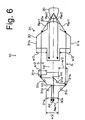
- Figs. 6 and 7 are cross-sectional views of the lighting unit 10 taken along lines B-B and A-A of Fig. 5 , respectively.
- the lighting unit 10 of the embodiment can be applied to a vehicle-mounted signal lamp and to a generally used illumination lamp.
- vehicle-mounted signal lamp examples include a rear position lamp, a stop lamp, a turn signal lamp, a daytime running lamp, and a position lamp.
- the lighting unit 10 can include an LED light source 20, a lens body 30, and others.
- the LED light source 20 can be an LED light source including at least one LED chip (a blue LED chip, for example) and a fluorescent substance (yellow fluorescent substance, for example).
- the LED light source 20 can emit white light (quasi white light) containing light which is part of light emitted from the LED chip and which has passed through the fluorescent substance, and light from the fluorescent substance, generated by being excited by the light emitted from the LED chip.
- the LED light source 20 can be arranged to face a side surface of the lens body 30 such that rays of light Ray1 emitted in a wide angle direction with respect to an optical axis AX of the LED light source 20 can travel toward the front and rear surfaces of the lens body 30, and that rays of light Ray2 emitted in a narrow angle direction with respect to the optical axis AX can enter the lens body 30 through the side surface of the lens body 30.
- the lens body 30 can be a lens body of a thickness of a, and have a plate form as a whole and made of a transparent resin (acrylic resin or polycarbonate resin, for example) or glass.
- the lens body 30 can include a first optical system 31, a second optical system 32, a third optical system 33, a first side surface 30a functioning as a light exiting surface 31e having a substantially rectangular shape greater in width than in thickness (see Fig. 5 ), a second side surface 30b opposite the first side surface 30a, and others.
- the first optical system 31 can include lens sections 31a (of a height of a/2), first light incident surfaces 31b, first total reflection surfaces 31c, second total reflection surfaces 31d, and others.
- the lens sections 31a can be formed on the front and rear surfaces of the lens body 30 such that the rays of light Ray1 traveling toward the front and rear surfaces of the lens body 30 enter the lens body 30.
- the lens sections 31a can collect the rays of light Ray1 such that the rays of light Ray1 can travel along the optical axis AX (in the embodiment, such that the rays of light Ray1 travel substantially parallel to the optical axis AX).
- the first light incident surfaces 31b can be arranged in optical paths of the rays of light Ray1 collected by the lens sections 31a, and can cause these rays of light Ray1 to enter the lens body 30 again.
- the first total reflection surfaces 31c can be arranged in optical paths of the rays of light Ray1 having entered the lens body 30 through the first light incident surfaces 31b, and can cause these rays of light Ray1 to reflect totally in a direction crossing the optical axis AX at substantially right angles (in the direction of the thickness of the lens body 30).
- the second total reflection surfaces 31d can be arranged in optical paths of the rays of light Ray1 having reflected totally off the first total reflection surfaces 31c, and can cause these rays of light Ray1 to reflect totally to exit as rays of light substantially parallel to the optical axis AX through a central region 31e1 (see Fig. 5 ) at substantially the center of the light exiting surface 31e.
- An air layer S (space) for causing the rays of light Ray1 collected by the lens sections 31a and traveling substantially parallel to the optical axis AX to pass therethrough can be formed between the lens sections 31a and the first light incident surfaces 31b (see Figs. 3 , 4 and 6 ).
- the first light incident surfaces 31b can be lens surfaces (of a height of a/2) substantially perpendicular to the rays of light Ray1 (perpendicular to a direction in which the rays of light Ray1 travel) so that the rays of light Ray1 do not make surface reflection.
- recesses H1 can be formed on the rear surface (and the front surface) of the lens body 30 (see Figs. 3 and 6 ), and parts of the recesses H1 (parts of surfaces forming the recesses H1) can function as the second total reflection surfaces 31d.
- the rays of light Ray1 which can be part of light emitted from the LED light source 20 and which are to travel toward the front and rear surfaces of the lens body 30 can be collected by the lens sections 31a to be converted to rays of light substantially parallel to the optical axis AX. Then, the rays of light Ray1 can pass through the air layer S (space) between the lens sections 31a and the first light incident surfaces 31b, and thereafter can enter the lens body 30 again through the first light incident surfaces 31b to travel inside the lens body 30.
- the rays of light Ray1 can be caused to reflect totally twice by the first total reflection surfaces 31c and the second total reflection surfaces 31d, and exit as rays of light substantially parallel to the optical axis AX through the light exiting surface 31e (central region 31e1, see Fig. 5 ).
- the second optical system 32 can include a second light incident surface 32a, third total reflection surfaces 32b, fourth total reflection surfaces 32c, and others.
- the second light incident surface 32a can be formed on a side surface (second side surface 30b) of the lens body 30.
- the second light incident surface 32a can collect the rays of light Ray2 emitted in a narrow angle direction with respect to the optical axis AX (in the embodiment, rays of light having directional characteristics by which the rays of light are very likely to travel at an angle of 20 degrees with respect to the center of the LED light source 20) such that the rays of light Ray2 can travel along the optical axis AX (in the embodiment, such that the rays of light Ray2 travel substantially parallel to the optical axis AX).
- the third total reflection surfaces 32b can be arranged in optical paths of the rays of light Ray2 collected by the second light incident surface 32a and having entered the lens body 30, and cause these rays of light Ray2 to reflect totally and sideways with respect to the optical axis AX.
- the fourth total reflection surfaces 32c can be arranged in optical paths of the rays of light Ray2 having reflected totally off the third total reflection surfaces 32b, and cause these rays of light Ray2 to reflect totally to exit as rays of light substantially parallel to the optical axis AX through outermost regions 31e2 (see Fig. 5 ) at outermost parts of the light exiting surface 31e.
- the fourth total reflection surfaces 32c can each include a plurality of separate total reflection surfaces 32c1 in a step-like pattern formed separately in the direction of the width of the lens body 30.
- a through hole H2 penetrating the lens body 30 from the front surface to the rear surface thereof can be formed ahead of the second light incident surface 32a (see Figs. 4 and 7 ).
- the through hole H2 (part of a surface forming the through hole H2 and, in the present exemplary embodiment, this part corresponds to surfaces tilted at an angle of 45 degrees from the optical axis AX) can function as the third total reflection surfaces 32b.
- the rays of light Ray2 emitted from the LED light source 20 in a narrow angle direction with respect to the optical axis AX can be collected by the second light incident surface 32a to be converted to rays of light substantially parallel to the optical axis AX, and then can travel inside the lens body 30. Then, the rays of light Ray2 can be caused to reflect totally twice by the third total reflection surfaces 32b and the fourth total reflection surfaces 32c (plurality of separate total reflection surfaces 32c1), and can exit as rays of light substantially parallel to the optical axis AX through the light exiting surface 31e (outermost regions 31e2, see Fig. 5 ).
- the third optical system 33 can include a third light incident surface 33a, fifth total reflection surfaces 33b, and others.
- the third light incident surface 33a can cause rays of light Ray3 emitted from the LED light source 20 in a wide angle direction with respect to the optical axis AX and in the direction of the width of the lens body 30 to enter the lens body 30.
- the fifth total reflection surfaces 33b can cause the rays of light Ray3 having entered the lens body 30 through the third light incident surface 33a to reflect totally to exit as rays of light substantially parallel to the optical axis AX through intermediate regions 31e3 (see Fig. 5 ) of the light exiting surface 31e between the central region 31e1 and the outermost regions 31e2.
- the third light incident surface 33a can be a lens surface in the form of an upright wall (in the form of a cylinder) extending from the periphery of the second light incident surface 32a toward the LED light source 20.
- the fifth total reflection surfaces 33b can be total reflection surfaces belonging to paraboloids of revolution and the focal point of which is set at an intersecting point (not shown) of extended lines of rays of light in a group (rays of light Ray3) having entered the lens body 30 after being refracted off the third light incident surface 33a.
- side surfaces of the lens body 30 can function as the fifth total reflection surfaces 33b.
- the rays of light Ray3 emitted from the LED light source 20 in a wide angle direction with respect to the optical axis AX and in the direction of the width of the lens body 30 can enter the lens body 30 through the third light incident surface 33a, and then travel inside the lens body 30. Then, the rays of light Ray3 can be caused to reflect totally by the fifth total reflection surfaces 33b, and exit as rays of light substantially parallel to the optical axis AX through the light exiting surface 31e (intermediate regions 31e3, see Fig. 5 ).
- the lens body 30 (each of the optical systems 31 to 33) makes it possible to form a linear light source for emitting linear light (see Fig. 5 ) through the light exiting surface 31e (central region 31e1, outermost regions 31e2, and intermediate regions 31e3).
- the rays of light Ray1 to travel toward the front and rear surfaces of the lens body 30 may be increased by reducing the thickness of the lens body 30.
- the first optical system 31 (lens sections 31a and others) can allow these rays of light Ray1 to travel toward the front and rear surfaces of the lens body 30 to enter the lens body 30 again, so that reduction of the efficiency of use of light to be caused by reducing the thickness of the lens body 30 will not occur.
- the present exemplary embodiment can provide the lighting unit 10 using the lens body 30 which is smaller in thickness and lighter in weight than a conventional lens body, and which is capable of achieving efficiency of use of light comparable to or higher than efficiency achieved by the conventional lens body.
- the presence of the air layer S (space) between the lens sections 31a and the first light incident surfaces 31b allows the lens body 30 to be still smaller in thickness and lighter in weight accordingly.
- the aforementioned exemplary embodiment can form a linear light source for emitting the rays of light Ray1, Ray2 and Ray3 (see Figs. 6 and 7 ) substantially parallel to the optical axis AX.
- controlling each of the optical elements makes it possible to form a linear light source of a substantially uniform intensity.
- use of the total reflection surfaces providing a reflectance of 100% allows further enhancement of the efficiency of use of light, compared to use of a reflection surface mirror finished by aluminum vapor deposition and the like (providing a reflectance of 90%, for example).
- coincidence between the optical axis AX of the LED light source 20 and the optical axis of the lens body 30 makes it possible to form a layout easily.
- the optical elements can be formed on the front and rear surfaces of the lens body 30, to which the presently disclosed subject matter is not intended to be limited.
- optical elements including lens section 31a, light incident surface 31b, total reflection surfaces 31c and 31d, and others may be provided only on either the front surface or the rear surface of the lens body 30 as shown in Fig. 8 .
- the heights of the lens section 31a and the first light incident surface 31b be the same as the thickness a of the lens body 30.
- This modification can achieve the same effect as that achieved by the aforementioned exemplary embodiment.
- the light exiting surface 31e may be given a lens cut formed thereon.
- the light exiting surface 31e may be flat, and a lens section given a lens cut may be provided ahead of the light exiting surface 31e.
- the lens cut can control the rays of light Ray1, Ray 2 and Ray3 substantially parallel to the optical axis AX, so that light can be distributed in accordance with a target light strength distribution.
- Fig. 9 shows a linear light source unit in accordance with the principles of the present invention.
- a plurality of the lens bodies 30 can be arranged side by side so as to form a lens body unit 300 for a large linear light source unit 100.
- This linear light source unit 100 can be formed by integrally molding a single lens body unit 300 as a unit or fixing a plurality of lens bodies 30 in place while arranging them side by side.
- a plurality of the large linear light source units 100 can be arranged in a vertical direction so that a large rectangular light source unit can be formed.
- the large linear light source unit 100 is applicable to an automobile signal lamp such as a tail lamp, a stop lamp, a turn signal lamp, a daytime running lamp, and a position lamp.
Landscapes
- Engineering & Computer Science (AREA)
- General Engineering & Computer Science (AREA)
- Physics & Mathematics (AREA)
- Microelectronics & Electronic Packaging (AREA)
- Optics & Photonics (AREA)
- Non-Portable Lighting Devices Or Systems Thereof (AREA)
- Lenses (AREA)
Claims (3)
- Linearlichtquelleneinheit (100), die Folgendes aufweist:eine Vielzahl von LED-Lichtquellen (20), undeine Vielzahl von Linsenkörpern (30), wobei jede LED-Lichtquelle (20) mit einem entsprechenden Linsenkörper (30) assoziiert ist, wobei die Linsenkörper (30) Seite an Seite angeordnet sind, um eine Linsenkörpereinheit (300) zu bilden,wobei jeder Linsenkörper (30) eine erste Seitenoberfläche (30a), die als eine Lichtaustrittsoberfläche mit einer im Wesentlichen rechteckigen Form, die größer in der Breite als in der Dicke ist, und eine zweite Seitenoberfläche (30b) gegenüberliegend der ersten Seitenoberfläche (30a) aufweist, wobei:die LED-Lichtquelle (20) so angeordnet ist, dass sie zu der zweiten Seitenoberfläche (30b) so weist, dass sich ein Lichtstrahl, der in einer Weitwinkelrichtung in Bezug auf eine optische Achse (AX) der LED-Lichtquelle (20) emittiert wird, zu den vorderen und hinteren Oberflächen des Linsenkörpers (30) fortbewegt, und dass ein Lichtstrahl, der in einer Engwinkelrichtung in Bezug auf die optische Achse (AX) emittiert wird, in den Linsenkörper (30) durch die zweite Seitenoberfläche (30b) eintritt;der Linsenkörper (30) konfiguriert ist, um ein erstes optisches System (31), ein zweites optisches System (32) und ein drittes optisches System (33) aufzuweisen;wobei das erste optische System (31) Folgendes aufweist:einen Linsenabschnitt (31a), der auf den vorderen und hinteren Oberflächen oder auf der vorderen oder hinteren Oberfläche des Linsenkörpers (30) so gebildet ist, dass ein Lichtstrahl, der sich zu den vorderen und hinteren Oberflächen oder zu der vorderen oder hinteren Oberfläche des Linsenkörpers (30) fortbewegt, in den Linsenkörper (30) eintritt, wobei der Linsenabschnitt (31a) den Lichtstrahl einfängt, so dass sich der Lichtstrahl entlang der optischen Achse (AX) fortbewegt;eine erste Lichteinfallsoberfläche (31b), die in einem optischen Pfad des Lichtstrahls angeordnet ist, der durch den Linsenabschnitt (31a) eingefangen wird, wobei die erste Lichteinfallsoberfläche (31b) bewirkt, dass der Lichtstrahl erneut in den Linsenkörper (30) eintritt;eine erste Gesamtreflexionsfläche (31c), die in einem optischen Pfad des Lichtstrahls angeordnet ist, der in den Linsenkörper (30) durch die erste Lichteintrittsfläche (31b) eingetreten ist, wobei die erste Gesamtreflexionsfläche (31c) bewirkt, dass der Lichtstrahl vollständig in einer Richtung reflektiert wird, die die optische Achse (AX) mit im Wesentlichen rechten Winkeln kreuzt; undeine zweite Gesamtreflexionsoberfläche (31d), die in einem optischen Pfad des reflektierten Lichtstrahls angeordnet ist, der vollständig von der ersten Gesamtreflexionsoberfläche (31c) reflektiert wurde, wobei die zweite Gesamtreflexionsoberfläche (31d) bewirkt, dass der reflektierte Lichtstrahl vollständig reflektiert wird, so dass er als ein Lichtstrahl im Wesentlichen parallel zu der optischen Achse (AX) durch einen Mittelbereich (31e1) der ersten Seitenoberfläche (30a) austritt, die als die Lichtaustrittsoberfläche fungiert;wobei das zweite optische System (32) konfiguriert ist, um Folgendes aufzuweisen:eine zweite Lichteintrittsoberfläche (32a), die auf der zweiten Seitenoberfläche (30b) gebildet ist, wobei die zweite Lichteintrittsoberfläche (32a) einen Lichtstrahl einfängt, der in einer Engwinkelrichtung in Bezug auf die optische Achse (AX) emittiert wird, so dass sich der Lichtstrahl entlang der optischen Achse (AX) fortbewegt;eine dritte Gesamtreflexionsoberfläche (32b), die in einem optischen Pfad des Lichtstrahls angeordnet ist, der durch die zweite Lichteintrittsoberfläche (32a) eingefangen wird und in den Linsenkörper (30) eingetreten ist, wobei die dritte Gesamtreflexionsoberfläche (32b) bewirkt, dass der Lichtstrahl vollständig und seitlich in Bezug auf die optische Achse (AX) reflektiert wird; und eine vierte Gesamtreflexionsoberfläche (32c), die in einem optischen Pfad des Lichtstrahls angeordnet ist, der vollständig von der dritten Reflexionsoberfläche (32b) reflektiert wurde, wobei die vierte Gesamtreflexionsoberfläche (32c) bewirkt, dass der Lichtstrahl vollständig reflektiert wird, um als ein Lichtstrahl im Wesentlichen parallel zu der optischen Achse (AX) durch einen äußersten Bereich (31e2) bei einem äußersten Teil der ersten Seitenoberfläche (30a) auszutreten, die als die Lichtaustrittsoberfläche fungiert;wobei das dritte optische System (33) konfiguriert ist, um Folgendes aufzuweisen:eine dritte Lichteintrittsoberfläche (33a), um zu bewirken, dass ein Lichtstrahl, der von der LED-Lichtquelle (20) in einer Weitwinkelrichtung in Bezug auf die optische Achse (AX) und in der Richtung der Breite des Linsenkörpers (30) emittiert wird, in den Linsenkörper (30) eintritt; undeine fünfte Gesamtreflexionsoberfläche (33b), um zu bewirken, dass der Lichtstrahl, der in den Linsenkörper (30) durch die dritte Lichteintrittsoberfläche (33a) eingetreten ist, vollständig reflektiert wird, um als ein Lichtstrahl im Wesentlichen parallel zu der optischen Achse (AX) durch einen Zwischenbereich zwischen dem Mittelbereich (31e1) und dem äußersten Bereich (31e2) der ersten Seitenoberfläche (30a), auszutreten, die als die Lichtaustrittsoberfläche fungiert; undeine Luftschicht (Raum), um zu bewirken, dass der Lichtstrahl, der durch den Linsenabschnitt (31a) eingefangen wird, um durch diese hindurchzugehen, zwischen dem Linsenabschnitt (31a) und der ersten Lichteinfallsoberfläche (31b) gebildet ist.
- Linearlichtquelleneinheit gemäß Anspruch 1, wobei die Linsenkörpereinheit (300) durch integrales Formen der Vielzahl von Linsenkörpern (30) als ein Ganzes gebildet wird.
- Linearlichtquelleneinheit gemäß Anspruch 1, wobei die Linsenkörpereinheit (300) durch Anordnen der Vielzahl von Linsenkörpern (30) Seite an Seite und durch Befestigen dieser an der Stelle gebildet wird.
Applications Claiming Priority (1)
| Application Number | Priority Date | Filing Date | Title |
|---|---|---|---|
| JP2011012298A JP5641332B2 (ja) | 2011-01-24 | 2011-01-24 | 灯具 |
Publications (3)
| Publication Number | Publication Date |
|---|---|
| EP2479486A2 EP2479486A2 (de) | 2012-07-25 |
| EP2479486A3 EP2479486A3 (de) | 2017-09-20 |
| EP2479486B1 true EP2479486B1 (de) | 2019-03-13 |
Family
ID=45654762
Family Applications (1)
| Application Number | Title | Priority Date | Filing Date |
|---|---|---|---|
| EP12000429.6A Active EP2479486B1 (de) | 2011-01-24 | 2012-01-24 | Fahrzeugsbeleuchtungseinheit |
Country Status (3)
| Country | Link |
|---|---|
| US (1) | US8506129B2 (de) |
| EP (1) | EP2479486B1 (de) |
| JP (1) | JP5641332B2 (de) |
Families Citing this family (45)
| Publication number | Priority date | Publication date | Assignee | Title |
|---|---|---|---|---|
| JP5569807B2 (ja) * | 2010-11-04 | 2014-08-13 | スタンレー電気株式会社 | 灯具 |
| AT510931B1 (de) * | 2010-12-22 | 2013-09-15 | Zizala Lichtsysteme Gmbh | Fahrzeugscheinwerfer mit led-lichtmodul |
| US8684575B2 (en) * | 2011-02-24 | 2014-04-01 | Stanley Electric Co., Ltd. | Lighting unit |
| AT512056B1 (de) | 2011-11-08 | 2013-05-15 | Zizala Lichtsysteme Gmbh | Lichtleitelement sowie lichteinheit |
| FR2993633B1 (fr) * | 2012-07-23 | 2018-12-07 | Valeo Vision | Guide de lumiere pour un dispositif d'eclairage et/ou de signalisation de vehicule automobile |
| FR2995977B1 (fr) * | 2012-09-26 | 2019-06-28 | Valeo Vision | Guide de lumiere pour un dispositif d'eclairage et/ou de signalisation de vehicule automobile |
| US9581751B2 (en) | 2013-01-30 | 2017-02-28 | Cree, Inc. | Optical waveguide and lamp including same |
| US9366396B2 (en) | 2013-01-30 | 2016-06-14 | Cree, Inc. | Optical waveguide and lamp including same |
| WO2014120915A2 (en) * | 2013-01-30 | 2014-08-07 | Cree, Inc. | Simplified low profile module with light guide for pendant, surface mount, wall mount and stand alone luminaires |
| US9869432B2 (en) | 2013-01-30 | 2018-01-16 | Cree, Inc. | Luminaires using waveguide bodies and optical elements |
| US9291320B2 (en) | 2013-01-30 | 2016-03-22 | Cree, Inc. | Consolidated troffer |
| US9625638B2 (en) | 2013-03-15 | 2017-04-18 | Cree, Inc. | Optical waveguide body |
| US9442243B2 (en) | 2013-01-30 | 2016-09-13 | Cree, Inc. | Waveguide bodies including redirection features and methods of producing same |
| JP6179138B2 (ja) * | 2013-03-13 | 2017-08-16 | 市光工業株式会社 | 車両用灯具 |
| US20150177439A1 (en) | 2013-03-15 | 2015-06-25 | Cree, Inc. | Optical Waveguide Bodies and Luminaires Utilizing Same |
| US10209429B2 (en) | 2013-03-15 | 2019-02-19 | Cree, Inc. | Luminaire with selectable luminous intensity pattern |
| US10502899B2 (en) * | 2013-03-15 | 2019-12-10 | Ideal Industries Lighting Llc | Outdoor and/or enclosed structure LED luminaire |
| US10379278B2 (en) * | 2013-03-15 | 2019-08-13 | Ideal Industries Lighting Llc | Outdoor and/or enclosed structure LED luminaire outdoor and/or enclosed structure LED luminaire having outward illumination |
| US10208923B2 (en) | 2013-03-15 | 2019-02-19 | Cree, Inc. | Optical components for luminaire |
| US9366799B2 (en) | 2013-03-15 | 2016-06-14 | Cree, Inc. | Optical waveguide bodies and luminaires utilizing same |
| US9798072B2 (en) | 2013-03-15 | 2017-10-24 | Cree, Inc. | Optical element and method of forming an optical element |
| US9651740B2 (en) | 2014-01-09 | 2017-05-16 | Cree, Inc. | Extraction film for optical waveguide and method of producing same |
| US12372219B2 (en) * | 2014-05-30 | 2025-07-29 | Cree Lighting Usa Llc | LED luminaire with a cavity, finned interior, and a curved outer wall extending from a surface on which the light source is mounted |
| JP2016006729A (ja) | 2014-06-20 | 2016-01-14 | スタンレー電気株式会社 | 車両用灯具 |
| US10451239B2 (en) * | 2014-07-08 | 2019-10-22 | Mitsubishi Electric Corporation | Headlight module and headlight device |
| ITTV20150058A1 (it) * | 2015-04-23 | 2016-10-23 | Automotive Lighting Italia Spa | Fanale automobilistico |
| JP6587849B2 (ja) | 2015-07-10 | 2019-10-09 | スタンレー電気株式会社 | 導光レンズ及び灯具 |
| CN108885350A (zh) * | 2016-03-21 | 2018-11-23 | 亮锐控股有限公司 | 照明布置 |
| US11719882B2 (en) | 2016-05-06 | 2023-08-08 | Ideal Industries Lighting Llc | Waveguide-based light sources with dynamic beam shaping |
| US10416377B2 (en) | 2016-05-06 | 2019-09-17 | Cree, Inc. | Luminaire with controllable light emission |
| EP3663637A1 (de) * | 2016-09-30 | 2020-06-10 | H.A. Automotive Systems, Inc. | Kondensator für abblendlichtmodul eines fahrzeugs |
| CZ2017338A3 (cs) * | 2017-06-13 | 2018-08-01 | Varroc Lighting Systems, s.r.o. | Světlovodivý optický systém |
| TWM551987U (zh) * | 2017-06-28 | 2017-11-21 | Depo Auto Parts Ind Co Ltd | 車用照明的導光裝置 |
| CN107740995A (zh) * | 2017-10-25 | 2018-02-27 | 上海小糸车灯有限公司 | 一种led全反射透镜、led导光体和汽车车灯 |
| WO2019080634A1 (zh) * | 2017-10-25 | 2019-05-02 | 华域视觉科技(上海)有限公司 | 一种led全反射透镜、led导光体和汽车车灯 |
| DE102017128841B4 (de) * | 2017-12-05 | 2020-08-20 | Dr. Ing. H.C. F. Porsche Aktiengesellschaft | Lichtleitkörper für eine Beleuchtungsvorrichtung eines Kraftfahrzeugs |
| CN109931571B (zh) * | 2017-12-19 | 2022-07-01 | 意大利汽车照明股份公司 | 用于车辆的照明装置 |
| CZ307945B6 (cs) * | 2018-01-08 | 2019-09-04 | Hella Autotechnik Nova S.R.O. | Prostředek pro zajištění homogenity světelného svazku |
| CN108644739B (zh) * | 2018-04-24 | 2020-05-08 | 广州市佛达信号设备有限公司 | 一种远近光多焦点透镜及模组 |
| CN110715257B (zh) * | 2018-07-13 | 2022-04-22 | 法雷奥照明湖北技术中心有限公司 | 光导装置、照明和/或信号指示装置以及机动车辆 |
| CZ2018392A3 (cs) * | 2018-08-03 | 2019-10-02 | Varroc Lighting Systems, s.r.o. | Světlovodivá optická jednotka a světlovodivý optický systém zahrnující světlovodivé optické jednotky |
| WO2021209492A1 (en) * | 2020-04-15 | 2021-10-21 | CommScope Connectivity Belgium BV | Device and method for sealing cables in telecommunications enclosures |
| CN113701079B (zh) * | 2020-05-21 | 2025-05-20 | 华域视觉科技(上海)有限公司 | 一种导光元件、车灯和车辆 |
| CN118129103A (zh) * | 2022-12-02 | 2024-06-04 | 本田技研工业株式会社 | 用于车辆用灯体的透镜结构 |
| CZ2024341A3 (cs) * | 2024-09-02 | 2025-10-29 | Ĺ KODA AUTO a.s. | Optický prvek pro automobilovou svítilnu |
Family Cites Families (14)
| Publication number | Priority date | Publication date | Assignee | Title |
|---|---|---|---|---|
| JPH11174968A (ja) * | 1997-12-15 | 1999-07-02 | Denso Corp | インジケータ用レンズ |
| JPH11284803A (ja) * | 1998-03-27 | 1999-10-15 | Citizen Electronics Co Ltd | 線状光源ユニット |
| JP2003317508A (ja) | 2002-04-23 | 2003-11-07 | Ichikoh Ind Ltd | 車両用灯具 |
| US6679621B2 (en) | 2002-06-24 | 2004-01-20 | Lumileds Lighting U.S., Llc | Side emitting LED and lens |
| JP2004047358A (ja) * | 2002-07-15 | 2004-02-12 | Mark:Kk | 導光体および導光板ユニット、ディスプレイ装置ならびに電子装置 |
| KR100611972B1 (ko) | 2003-06-10 | 2006-08-11 | 삼성전자주식회사 | 소형광원모듈 및 이를 채용한 투사형 화상표시장치 |
| JP4290601B2 (ja) * | 2004-05-17 | 2009-07-08 | 株式会社小糸製作所 | 車両用灯具ユニットおよび車両用灯具 |
| EP1653258B1 (de) * | 2004-10-28 | 2007-03-21 | Delphi Technologies, Inc. | Fahrzeugleuchte |
| JP4458359B2 (ja) | 2005-06-06 | 2010-04-28 | スタンレー電気株式会社 | レンズおよびレンズユニット並びにそれらを具備する灯具 |
| CN101078795B (zh) * | 2006-05-24 | 2010-05-12 | 清华大学 | 导光板及背光模组 |
| JP2008160480A (ja) * | 2006-12-22 | 2008-07-10 | Ushio Inc | 線状光源装置 |
| JP4888429B2 (ja) * | 2008-03-18 | 2012-02-29 | 株式会社Jvcケンウッド | インジケータ装置 |
| JP2010135124A (ja) * | 2008-12-02 | 2010-06-17 | Harison Toshiba Lighting Corp | 車両用照明装置 |
| JP5569807B2 (ja) * | 2010-11-04 | 2014-08-13 | スタンレー電気株式会社 | 灯具 |
-
2011
- 2011-01-24 JP JP2011012298A patent/JP5641332B2/ja not_active Expired - Fee Related
-
2012
- 2012-01-24 US US13/357,584 patent/US8506129B2/en not_active Expired - Fee Related
- 2012-01-24 EP EP12000429.6A patent/EP2479486B1/de active Active
Non-Patent Citations (1)
| Title |
|---|
| None * |
Also Published As
| Publication number | Publication date |
|---|---|
| EP2479486A2 (de) | 2012-07-25 |
| US8506129B2 (en) | 2013-08-13 |
| JP5641332B2 (ja) | 2014-12-17 |
| JP2012155903A (ja) | 2012-08-16 |
| US20120188774A1 (en) | 2012-07-26 |
| EP2479486A3 (de) | 2017-09-20 |
Similar Documents
| Publication | Publication Date | Title |
|---|---|---|
| EP2479486B1 (de) | Fahrzeugsbeleuchtungseinheit | |
| EP2450725B1 (de) | Beleuchtungsvorrichtung | |
| JP5440857B2 (ja) | 車両用灯具ユニット、及び、車両用灯具 | |
| EP3456587B1 (de) | Lichtstrahleinstellvorrichtung, fahrzeuglampe und kraftfahrzeug | |
| EP2693105B1 (de) | Fahrzeugbeleuchtungseinheit | |
| US8591083B2 (en) | Vehicular lamp | |
| US8678628B2 (en) | Projection lens for a vehicle light | |
| JP2022535809A (ja) | 車両用ランプ光学素子、車両用ランプモジュール及び車両 | |
| US20160084469A1 (en) | Lighting apparatus and automobile having lighting apparatus mounted therein | |
| JP2006522442A (ja) | テールランプ、とりわけ自動車用の後部ストップランプ | |
| US8684575B2 (en) | Lighting unit | |
| US8231255B2 (en) | Vehicle light | |
| EP4137744B1 (de) | Optische einheit für fahrzeuglampe, fahrzeuglampenmodul und fahrzeug | |
| US20070247862A1 (en) | Lighting or signalling device with depth effect | |
| JP7317205B2 (ja) | 光学素子、車両ランプモジュール、車両ランプ及び車両 | |
| JP2016091825A (ja) | 車両用灯具 | |
| US9862306B2 (en) | Vehicle decorative lighting device and vehicle lamp | |
| KR101486818B1 (ko) | 차량용 램프 | |
| US11428377B2 (en) | Lamp module for vehicle, and lamp for vehicle including lamp module | |
| US10823363B2 (en) | Vehicular lamp | |
| KR20150071410A (ko) | 차량용 램프 | |
| US11555592B1 (en) | Lamp for vehicle and vehicle including the same | |
| CN220366317U (zh) | 导光元件、照明和/或信号指示装置以及车辆 |
Legal Events
| Date | Code | Title | Description |
|---|---|---|---|
| PUAI | Public reference made under article 153(3) epc to a published international application that has entered the european phase |
Free format text: ORIGINAL CODE: 0009012 |
|
| AK | Designated contracting states |
Kind code of ref document: A2 Designated state(s): AL AT BE BG CH CY CZ DE DK EE ES FI FR GB GR HR HU IE IS IT LI LT LU LV MC MK MT NL NO PL PT RO RS SE SI SK SM TR |
|
| AX | Request for extension of the european patent |
Extension state: BA ME |
|
| PUAL | Search report despatched |
Free format text: ORIGINAL CODE: 0009013 |
|
| AK | Designated contracting states |
Kind code of ref document: A3 Designated state(s): AL AT BE BG CH CY CZ DE DK EE ES FI FR GB GR HR HU IE IS IT LI LT LU LV MC MK MT NL NO PL PT RO RS SE SI SK SM TR |
|
| AX | Request for extension of the european patent |
Extension state: BA ME |
|
| RIC1 | Information provided on ipc code assigned before grant |
Ipc: F21S 8/10 20060101AFI20170811BHEP Ipc: F21V 5/00 20150101ALI20170811BHEP Ipc: F21V 8/00 20060101ALI20170811BHEP |
|
| STAA | Information on the status of an ep patent application or granted ep patent |
Free format text: STATUS: REQUEST FOR EXAMINATION WAS MADE |
|
| 17P | Request for examination filed |
Effective date: 20180320 |
|
| RBV | Designated contracting states (corrected) |
Designated state(s): AL AT BE BG CH CY CZ DE DK EE ES FI FR GB GR HR HU IE IS IT LI LT LU LV MC MK MT NL NO PL PT RO RS SE SI SK SM TR |
|
| REG | Reference to a national code |
Ref country code: DE Ref legal event code: R079 Ref document number: 602012057637 Country of ref document: DE Free format text: PREVIOUS MAIN CLASS: F21S0008100000 Ipc: F21S0041143000 |
|
| RIC1 | Information provided on ipc code assigned before grant |
Ipc: F21Y 115/10 20160101ALN20180717BHEP Ipc: F21S 41/265 20180101ALI20180717BHEP Ipc: F21S 41/26 20180101ALI20180717BHEP Ipc: F21S 41/143 20180101AFI20180717BHEP Ipc: F21S 43/241 20180101ALI20180717BHEP Ipc: F21S 43/243 20180101ALI20180717BHEP Ipc: F21S 43/14 20180101ALI20180717BHEP Ipc: F21S 43/239 20180101ALI20180717BHEP |
|
| GRAP | Despatch of communication of intention to grant a patent |
Free format text: ORIGINAL CODE: EPIDOSNIGR1 |
|
| STAA | Information on the status of an ep patent application or granted ep patent |
Free format text: STATUS: GRANT OF PATENT IS INTENDED |
|
| INTG | Intention to grant announced |
Effective date: 20180906 |
|
| GRAS | Grant fee paid |
Free format text: ORIGINAL CODE: EPIDOSNIGR3 |
|
| GRAA | (expected) grant |
Free format text: ORIGINAL CODE: 0009210 |
|
| STAA | Information on the status of an ep patent application or granted ep patent |
Free format text: STATUS: THE PATENT HAS BEEN GRANTED |
|
| AK | Designated contracting states |
Kind code of ref document: B1 Designated state(s): AL AT BE BG CH CY CZ DE DK EE ES FI FR GB GR HR HU IE IS IT LI LT LU LV MC MK MT NL NO PL PT RO RS SE SI SK SM TR |
|
| REG | Reference to a national code |
Ref country code: GB Ref legal event code: FG4D |
|
| REG | Reference to a national code |
Ref country code: CH Ref legal event code: EP Ref country code: AT Ref legal event code: REF Ref document number: 1108192 Country of ref document: AT Kind code of ref document: T Effective date: 20190315 |
|
| REG | Reference to a national code |
Ref country code: IE Ref legal event code: FG4D |
|
| REG | Reference to a national code |
Ref country code: DE Ref legal event code: R096 Ref document number: 602012057637 Country of ref document: DE |
|
| REG | Reference to a national code |
Ref country code: NL Ref legal event code: MP Effective date: 20190313 |
|
| REG | Reference to a national code |
Ref country code: LT Ref legal event code: MG4D |
|
| PG25 | Lapsed in a contracting state [announced via postgrant information from national office to epo] |
Ref country code: NO Free format text: LAPSE BECAUSE OF FAILURE TO SUBMIT A TRANSLATION OF THE DESCRIPTION OR TO PAY THE FEE WITHIN THE PRESCRIBED TIME-LIMIT Effective date: 20190613 Ref country code: FI Free format text: LAPSE BECAUSE OF FAILURE TO SUBMIT A TRANSLATION OF THE DESCRIPTION OR TO PAY THE FEE WITHIN THE PRESCRIBED TIME-LIMIT Effective date: 20190313 Ref country code: SE Free format text: LAPSE BECAUSE OF FAILURE TO SUBMIT A TRANSLATION OF THE DESCRIPTION OR TO PAY THE FEE WITHIN THE PRESCRIBED TIME-LIMIT Effective date: 20190313 Ref country code: LT Free format text: LAPSE BECAUSE OF FAILURE TO SUBMIT A TRANSLATION OF THE DESCRIPTION OR TO PAY THE FEE WITHIN THE PRESCRIBED TIME-LIMIT Effective date: 20190313 |
|
| PG25 | Lapsed in a contracting state [announced via postgrant information from national office to epo] |
Ref country code: LV Free format text: LAPSE BECAUSE OF FAILURE TO SUBMIT A TRANSLATION OF THE DESCRIPTION OR TO PAY THE FEE WITHIN THE PRESCRIBED TIME-LIMIT Effective date: 20190313 Ref country code: NL Free format text: LAPSE BECAUSE OF FAILURE TO SUBMIT A TRANSLATION OF THE DESCRIPTION OR TO PAY THE FEE WITHIN THE PRESCRIBED TIME-LIMIT Effective date: 20190313 Ref country code: HR Free format text: LAPSE BECAUSE OF FAILURE TO SUBMIT A TRANSLATION OF THE DESCRIPTION OR TO PAY THE FEE WITHIN THE PRESCRIBED TIME-LIMIT Effective date: 20190313 Ref country code: BG Free format text: LAPSE BECAUSE OF FAILURE TO SUBMIT A TRANSLATION OF THE DESCRIPTION OR TO PAY THE FEE WITHIN THE PRESCRIBED TIME-LIMIT Effective date: 20190613 Ref country code: GR Free format text: LAPSE BECAUSE OF FAILURE TO SUBMIT A TRANSLATION OF THE DESCRIPTION OR TO PAY THE FEE WITHIN THE PRESCRIBED TIME-LIMIT Effective date: 20190614 Ref country code: RS Free format text: LAPSE BECAUSE OF FAILURE TO SUBMIT A TRANSLATION OF THE DESCRIPTION OR TO PAY THE FEE WITHIN THE PRESCRIBED TIME-LIMIT Effective date: 20190313 |
|
| REG | Reference to a national code |
Ref country code: AT Ref legal event code: MK05 Ref document number: 1108192 Country of ref document: AT Kind code of ref document: T Effective date: 20190313 |
|
| PG25 | Lapsed in a contracting state [announced via postgrant information from national office to epo] |
Ref country code: EE Free format text: LAPSE BECAUSE OF FAILURE TO SUBMIT A TRANSLATION OF THE DESCRIPTION OR TO PAY THE FEE WITHIN THE PRESCRIBED TIME-LIMIT Effective date: 20190313 Ref country code: ES Free format text: LAPSE BECAUSE OF FAILURE TO SUBMIT A TRANSLATION OF THE DESCRIPTION OR TO PAY THE FEE WITHIN THE PRESCRIBED TIME-LIMIT Effective date: 20190313 Ref country code: CZ Free format text: LAPSE BECAUSE OF FAILURE TO SUBMIT A TRANSLATION OF THE DESCRIPTION OR TO PAY THE FEE WITHIN THE PRESCRIBED TIME-LIMIT Effective date: 20190313 Ref country code: RO Free format text: LAPSE BECAUSE OF FAILURE TO SUBMIT A TRANSLATION OF THE DESCRIPTION OR TO PAY THE FEE WITHIN THE PRESCRIBED TIME-LIMIT Effective date: 20190313 Ref country code: IT Free format text: LAPSE BECAUSE OF FAILURE TO SUBMIT A TRANSLATION OF THE DESCRIPTION OR TO PAY THE FEE WITHIN THE PRESCRIBED TIME-LIMIT Effective date: 20190313 Ref country code: PT Free format text: LAPSE BECAUSE OF FAILURE TO SUBMIT A TRANSLATION OF THE DESCRIPTION OR TO PAY THE FEE WITHIN THE PRESCRIBED TIME-LIMIT Effective date: 20190713 Ref country code: SK Free format text: LAPSE BECAUSE OF FAILURE TO SUBMIT A TRANSLATION OF THE DESCRIPTION OR TO PAY THE FEE WITHIN THE PRESCRIBED TIME-LIMIT Effective date: 20190313 Ref country code: AL Free format text: LAPSE BECAUSE OF FAILURE TO SUBMIT A TRANSLATION OF THE DESCRIPTION OR TO PAY THE FEE WITHIN THE PRESCRIBED TIME-LIMIT Effective date: 20190313 |
|
| PG25 | Lapsed in a contracting state [announced via postgrant information from national office to epo] |
Ref country code: PL Free format text: LAPSE BECAUSE OF FAILURE TO SUBMIT A TRANSLATION OF THE DESCRIPTION OR TO PAY THE FEE WITHIN THE PRESCRIBED TIME-LIMIT Effective date: 20190313 Ref country code: SM Free format text: LAPSE BECAUSE OF FAILURE TO SUBMIT A TRANSLATION OF THE DESCRIPTION OR TO PAY THE FEE WITHIN THE PRESCRIBED TIME-LIMIT Effective date: 20190313 |
|
| REG | Reference to a national code |
Ref country code: DE Ref legal event code: R097 Ref document number: 602012057637 Country of ref document: DE |
|
| PG25 | Lapsed in a contracting state [announced via postgrant information from national office to epo] |
Ref country code: AT Free format text: LAPSE BECAUSE OF FAILURE TO SUBMIT A TRANSLATION OF THE DESCRIPTION OR TO PAY THE FEE WITHIN THE PRESCRIBED TIME-LIMIT Effective date: 20190313 Ref country code: IS Free format text: LAPSE BECAUSE OF FAILURE TO SUBMIT A TRANSLATION OF THE DESCRIPTION OR TO PAY THE FEE WITHIN THE PRESCRIBED TIME-LIMIT Effective date: 20190713 |
|
| PLBE | No opposition filed within time limit |
Free format text: ORIGINAL CODE: 0009261 |
|
| STAA | Information on the status of an ep patent application or granted ep patent |
Free format text: STATUS: NO OPPOSITION FILED WITHIN TIME LIMIT |
|
| PG25 | Lapsed in a contracting state [announced via postgrant information from national office to epo] |
Ref country code: DK Free format text: LAPSE BECAUSE OF FAILURE TO SUBMIT A TRANSLATION OF THE DESCRIPTION OR TO PAY THE FEE WITHIN THE PRESCRIBED TIME-LIMIT Effective date: 20190313 |
|
| 26N | No opposition filed |
Effective date: 20191216 |
|
| PG25 | Lapsed in a contracting state [announced via postgrant information from national office to epo] |
Ref country code: SI Free format text: LAPSE BECAUSE OF FAILURE TO SUBMIT A TRANSLATION OF THE DESCRIPTION OR TO PAY THE FEE WITHIN THE PRESCRIBED TIME-LIMIT Effective date: 20190313 |
|
| PG25 | Lapsed in a contracting state [announced via postgrant information from national office to epo] |
Ref country code: TR Free format text: LAPSE BECAUSE OF FAILURE TO SUBMIT A TRANSLATION OF THE DESCRIPTION OR TO PAY THE FEE WITHIN THE PRESCRIBED TIME-LIMIT Effective date: 20190313 |
|
| PG25 | Lapsed in a contracting state [announced via postgrant information from national office to epo] |
Ref country code: MC Free format text: LAPSE BECAUSE OF FAILURE TO SUBMIT A TRANSLATION OF THE DESCRIPTION OR TO PAY THE FEE WITHIN THE PRESCRIBED TIME-LIMIT Effective date: 20190313 |
|
| REG | Reference to a national code |
Ref country code: CH Ref legal event code: PL |
|
| REG | Reference to a national code |
Ref country code: BE Ref legal event code: MM Effective date: 20200131 |
|
| PG25 | Lapsed in a contracting state [announced via postgrant information from national office to epo] |
Ref country code: LU Free format text: LAPSE BECAUSE OF NON-PAYMENT OF DUE FEES Effective date: 20200124 |
|
| PG25 | Lapsed in a contracting state [announced via postgrant information from national office to epo] |
Ref country code: LI Free format text: LAPSE BECAUSE OF NON-PAYMENT OF DUE FEES Effective date: 20200131 Ref country code: CH Free format text: LAPSE BECAUSE OF NON-PAYMENT OF DUE FEES Effective date: 20200131 Ref country code: BE Free format text: LAPSE BECAUSE OF NON-PAYMENT OF DUE FEES Effective date: 20200131 |
|
| PG25 | Lapsed in a contracting state [announced via postgrant information from national office to epo] |
Ref country code: IE Free format text: LAPSE BECAUSE OF NON-PAYMENT OF DUE FEES Effective date: 20200124 |
|
| PG25 | Lapsed in a contracting state [announced via postgrant information from national office to epo] |
Ref country code: MT Free format text: LAPSE BECAUSE OF FAILURE TO SUBMIT A TRANSLATION OF THE DESCRIPTION OR TO PAY THE FEE WITHIN THE PRESCRIBED TIME-LIMIT Effective date: 20190313 Ref country code: CY Free format text: LAPSE BECAUSE OF FAILURE TO SUBMIT A TRANSLATION OF THE DESCRIPTION OR TO PAY THE FEE WITHIN THE PRESCRIBED TIME-LIMIT Effective date: 20190313 |
|
| PG25 | Lapsed in a contracting state [announced via postgrant information from national office to epo] |
Ref country code: MK Free format text: LAPSE BECAUSE OF FAILURE TO SUBMIT A TRANSLATION OF THE DESCRIPTION OR TO PAY THE FEE WITHIN THE PRESCRIBED TIME-LIMIT Effective date: 20190313 |
|
| PGFP | Annual fee paid to national office [announced via postgrant information from national office to epo] |
Ref country code: GB Payment date: 20221201 Year of fee payment: 12 Ref country code: FR Payment date: 20221208 Year of fee payment: 12 |
|
| PGFP | Annual fee paid to national office [announced via postgrant information from national office to epo] |
Ref country code: DE Payment date: 20221130 Year of fee payment: 12 |
|
| REG | Reference to a national code |
Ref country code: DE Ref legal event code: R119 Ref document number: 602012057637 Country of ref document: DE |
|
| GBPC | Gb: european patent ceased through non-payment of renewal fee |
Effective date: 20240124 |
|
| PG25 | Lapsed in a contracting state [announced via postgrant information from national office to epo] |
Ref country code: DE Free format text: LAPSE BECAUSE OF NON-PAYMENT OF DUE FEES Effective date: 20240801 |
|
| PG25 | Lapsed in a contracting state [announced via postgrant information from national office to epo] |
Ref country code: GB Free format text: LAPSE BECAUSE OF NON-PAYMENT OF DUE FEES Effective date: 20240124 |
|
| PG25 | Lapsed in a contracting state [announced via postgrant information from national office to epo] |
Ref country code: FR Free format text: LAPSE BECAUSE OF NON-PAYMENT OF DUE FEES Effective date: 20240131 |
|
| PG25 | Lapsed in a contracting state [announced via postgrant information from national office to epo] |
Ref country code: GB Free format text: LAPSE BECAUSE OF NON-PAYMENT OF DUE FEES Effective date: 20240124 Ref country code: FR Free format text: LAPSE BECAUSE OF NON-PAYMENT OF DUE FEES Effective date: 20240131 Ref country code: DE Free format text: LAPSE BECAUSE OF NON-PAYMENT OF DUE FEES Effective date: 20240801 |