EP4136335B1 - Schaltung zur messung der drehzahl eines motors - Google Patents
Schaltung zur messung der drehzahl eines motors Download PDFInfo
- Publication number
- EP4136335B1 EP4136335B1 EP20721670.6A EP20721670A EP4136335B1 EP 4136335 B1 EP4136335 B1 EP 4136335B1 EP 20721670 A EP20721670 A EP 20721670A EP 4136335 B1 EP4136335 B1 EP 4136335B1
- Authority
- EP
- European Patent Office
- Prior art keywords
- state
- measurement circuit
- diagnostic
- signal
- voltage
- Prior art date
- Legal status (The legal status is an assumption and is not a legal conclusion. Google has not performed a legal analysis and makes no representation as to the accuracy of the status listed.)
- Active
Links
Images



Classifications
-
- F—MECHANICAL ENGINEERING; LIGHTING; HEATING; WEAPONS; BLASTING
- F02—COMBUSTION ENGINES; HOT-GAS OR COMBUSTION-PRODUCT ENGINE PLANTS
- F02D—CONTROLLING COMBUSTION ENGINES
- F02D41/00—Electrical control of supply of combustible mixture or its constituents
- F02D41/22—Safety or indicating devices for abnormal conditions
- F02D41/222—Safety or indicating devices for abnormal conditions relating to the failure of sensors or parameter detection devices
-
- F—MECHANICAL ENGINEERING; LIGHTING; HEATING; WEAPONS; BLASTING
- F02—COMBUSTION ENGINES; HOT-GAS OR COMBUSTION-PRODUCT ENGINE PLANTS
- F02D—CONTROLLING COMBUSTION ENGINES
- F02D41/00—Electrical control of supply of combustible mixture or its constituents
- F02D41/24—Electrical control of supply of combustible mixture or its constituents characterised by the use of digital means
- F02D41/26—Electrical control of supply of combustible mixture or its constituents characterised by the use of digital means using computer, e.g. microprocessor
- F02D41/28—Interface circuits
- F02D2041/281—Interface circuits between sensors and control unit
- F02D2041/285—Interface circuits between sensors and control unit the sensor having a signal processing unit external to the engine control unit
-
- F—MECHANICAL ENGINEERING; LIGHTING; HEATING; WEAPONS; BLASTING
- F02—COMBUSTION ENGINES; HOT-GAS OR COMBUSTION-PRODUCT ENGINE PLANTS
- F02D—CONTROLLING COMBUSTION ENGINES
- F02D2200/00—Input parameters for engine control
- F02D2200/02—Input parameters for engine control the parameters being related to the engine
- F02D2200/10—Parameters related to the engine output, e.g. engine torque or engine speed
- F02D2200/101—Engine speed
-
- Y—GENERAL TAGGING OF NEW TECHNOLOGICAL DEVELOPMENTS; GENERAL TAGGING OF CROSS-SECTIONAL TECHNOLOGIES SPANNING OVER SEVERAL SECTIONS OF THE IPC; TECHNICAL SUBJECTS COVERED BY FORMER USPC CROSS-REFERENCE ART COLLECTIONS [XRACs] AND DIGESTS
- Y02—TECHNOLOGIES OR APPLICATIONS FOR MITIGATION OR ADAPTATION AGAINST CLIMATE CHANGE
- Y02T—CLIMATE CHANGE MITIGATION TECHNOLOGIES RELATED TO TRANSPORTATION
- Y02T10/00—Road transport of goods or passengers
- Y02T10/10—Internal combustion engine [ICE] based vehicles
- Y02T10/40—Engine management systems
Definitions
- the present invention relates to processing of an electrical signal that is descriptive of a speed of rotating component, such as the speed of a combustion engine.
- the engine speed measurement typically relies on a speed sensor arranged to detect rotation speed of the crankshaft and/or the flywheel of the combustion engine and to generate an electrical speed signal that comprises a pulse train whose pulse frequency is descriptive of the speed of the crankshaft/flywheel of the combustion engine, thereby serving as an indication of a rotation speed of the combustion engine.
- Engine speed measurement using such a basic mechanism is well known in the art it is therefore not discussed herein in more detail.
- Any anomalies in engine control or engine performance due to errors or inaccuracies in the engine speed measurement may result in increased fuel consumption and/or increased emissions or may lead to compromised or even interrupted power supply. While such compromised performance of a combustion engine in any usage scenario should be avoided to extent possible, such compromised performance may be especially disadvantageous in usage scenarios where one or more combustion engines are applied as the supply of mechanical energy in demanding industrial environments such as power plants, marine vessels, offshore platforms such as oil rigs, etc. where the combustion engine(s) are continuously operated for prolonged periods of time and where efficient and uninterrupted power supply from the combustion engine is typically a critical characteristic.
- reliability of the engine speed measurement does not only concern numerical accuracy of the measured engine speed but also involves recognition of various error conditions that may disturb or completely disable the engine speed measurement to facilitate efficient and swift maintenance in case such condition arises.
- WO 99/27377 A1 discloses a symmetric voltage divider is connected between the terminals of an inductive sensor. The tap of said voltage divider is fed to a reference voltage via a resistor. A diagnostic voltage is present on the tap. The diagnostic voltage is first compared with two threshold values at rest and then sampled in an operating state. The difference is calculated from the largest and smallest sample value, said difference being compared with a third threshold value. Short circuits or line interruptions are recognized/displayed from the comparison result.
- WO 2004/070319 A1 discloses a diagnostic method for a sensor in a motor vehicle equipped with an internal combustion engine. According to said method, during the operation of the motor vehicle, an output signal of the sensor is analysed to determine whether a maximum value of the output signal falls below a first threshold value and/or whether a minimum value of the output signal exceeds a second threshold value. In the latter case, a signal is sent to a control unit, said signal indicating to the latter that the sensor may deliver incorrect data when the motor vehicle is started again.
- a circuit for measuring a rotation speed of a combustion engine comprising a state detector coupled between an operating voltage and a ground potential and coupled to receive, from a speed sensor, an electrical signal that has a time-varying signal voltage that exhibits local maxima at a frequency that has a predefined relationship to the rotation speed, wherein the state detector is arranged to derive, based on the electrical signal, a state indication that indicates whether the electrical signal represents one of a high state or a low state, and a diagnostic signal that is descriptive of the operational state of the speed measurement circuit, wherein the diagnostic signal conveys a diagnostic value that is descriptive of current operational state of the speed measurement circuit, wherein current operational state is one of a normal operational state or an abnormal operational state and wherein the state detector is arranged to derive the diagnostic value based on the signal voltage of the electrical signal; and a controller coupled to receive the state indications and the diagnostic signal and arranged to compute the rotation speed based on a time series of the state indications in dependence of the diagnostic signal
- a method for measuring a rotation speed of a combustion engine comprising receiving, from a speed sensor coupled to measure the rotation speed, an electrical signal that has a time-varying signal voltage that exhibits local maxima at a frequency that has a predefined relationship to the rotation speed; deriving, based on the electrical signal, a state indication that indicates whether the electrical signal represents one of a high state or a low state; deriving, based on the electrical signal, a diagnostic signal that is descriptive of the operational state of the speed measurement circuit, wherein the diagnostic signal conveys a diagnostic value that is descriptive of current operational state of the speed measurement circuit, wherein current operational state is one of a normal operational state or an abnormal operational state and wherein the diagnostic value is derived based on the signal voltage of the electrical signal; and deriving the rotation speed based on a time series of the state indications in dependence of the diagnostic signal in view of said predefined relationship, wherein the diagnostic value is derived via application of the following: two or more predefined signal voltage sub-
- FIG. 1 schematically illustrates a speed measurement circuit 100 according to an example, (conceptually) divided into an analog subsystem 100a and a digital subsystem 100b.
- the speed measurement circuit 100 comprises a speed sensor 110 is coupled to a state detector 120 by a signal line 111.
- the speed sensor 110 is arranged to provide an analog electrical signal via the signal line 111 to the state detector 120, which is arranged to determine whether the electrical signal currently received thereat represents one of a high state or a low state and to issue a respective state indication 121 to a controller 130 to enable rotation speed calculation therein based on a time series of state indications 121.
- the speed sensor 110 may comprise, for example, a hall sensor.
- the speed sensor 110 and the state detector 120 may be coupled to operating voltage V s and to a ground potential V GND .
- the speed sensor 110 is arranged to derive the electrical signal as one that is descriptive of rotation speed of a rotary component, e.g. the rotation speed of a crankshaft or a flywheel of a combustion engine.
- rotation speed of a rotary component e.g. the rotation speed of a crankshaft or a flywheel of a combustion engine.
- the present disclosure simply refers rotation speed of a combustion engine.
- the rotation speed of a component of the combustion engine serves as a non-limiting example and the speed measurements circuits described in the present disclosure are applicable for measuring rotation speeds also in frameworks different from combustion engines.
- the operating voltage V s may be provided by a suitable DC voltage source, whereas characteristics of the first resistor R 1 as well as the high and low reference voltages V ref,high , V ref,low may be selected in view of the characteristics of the applied speed sensor 110 and/or the applied operating voltage V s .
- the controller 130 may be arranged to compute the rotation speed of the combustion engine based on the time series of state indications 121 obtained from the state detector 120 in view of the knowledge of the predefined relationship between the frequency of local maxima in the signal voltage V 111 and the rotation speed and provide a speed indication 131 that indicates the derived rotation speed.
- the controller 130 may be arranged to derive the rotation speed directly based on respective timings of the state indications 121 obtained from the state detector 120, whereas in another example the controller may be arranged to construct a digital speed signal based on the state indications 121 obtained from the state detector 120 and to derive the rotation speed based on the digital speed signal.
- reception of the first high state indication that follows reception of a low state indication indicates a rising edge of the digital speed signal while a time period starting from the rising edge and continuing until reception of the next low state indication may represent a binary high state of the digital speed signal
- reception of the first low state indication that follows reception of a high state indication indicates a falling edge of the digital speed signal while a time period starting from the falling edge and continuing until reception of the next high state indication may represent a binary low state of the digital speed signal.
- the resulting digital speed signal typically consists of alternating periods of binary high states and binary low states (e.g. binary ones and binary zeros), i.e. a pulse train, wherein the pulse frequency substantially matches the frequency of local maxima in the signal voltage V 111 .
- Figure 2 schematically illustrates an implementation of the speed measurement circuit 100 according to an example, where the state detector 120 comprises a first resistor R 1 coupled between the signal line 111 and the ground potential V GND and where the signal line 111 is coupled to a first input terminal of a first comparator 122 and to a second input terminal of a second comparator 124.
- a second input terminal of the first comparator 122 is coupled to the high reference voltage V ref,high and a first input terminal of the second comparator 124 is coupled to the low reference voltage V ref,low .
- the first comparator 122 may be arranged to provide a first predefined voltage (e.g.
- the second comparator 124 may be arranged to provide the first predefined voltage when the signal voltage V 111 exceeds the low reference voltage V ref,low and to provide the second predefined voltage that serves as the low state indication in response to the signal voltage V 111 being smaller than the low reference voltage V ref,low .
- the respective voltages provided from the respective outputs of the first and second comparators 122, 124 serve as the state indication 121.
- Figure 3 schematically illustrates the relationship between the signal voltage V 111 received at the state detector 120 and the pulse train derived in the controller 130 according to an example.
- the illustration (a) depicts the signal voltage V 111 as a function of time
- the illustration (b) depicts the pulse train derivable based on the time series of state indications 121 derived from the signal voltage V 111 of the illustration (a).
- the first and second comparators 122, 124 serve to provide an edge detection functionality via providing the time series of state indications 121, which in turn enables computation of the rotation speed either directly based on respective frequencies of the raising edges and/or falling edges derivable based on the time series of state indications 121 or via derivation of the digital speed signal in the form of the pulse train, as described in the foregoing with references to the controller 130.
- FIG. 4 schematically illustrates an improved speed measurement circuit 200 according to an example, (conceptually) divided into an analog subsystem 200a and a digital subsystem 200b.
- the speed measurement circuit 200 comprises the speed sensor 110, a state detector 220 and a controller 230.
- the speed sensor 110 is arranged to provide an analog electrical signal via the signal line 111 to the state detector 220, which is arranged to determine whether the electrical signal currently received thereat represents the high state or the low state and to issue a respective state indication 121 to the controller 230 to enable rotation speed calculation therein based on a time series of state indications 121.
- the state detector 220 may be arranged to derive based on the electrical signal, a diagnostic signal 223 that is descriptive of at least one aspect of an operational state of the speed measurement circuit 200 (e.g. that of the analog subsystem 200a) for provision to the controller 230.
- the speed sensor 110 and the state detector 220 may be coupled to an operating voltage V s and to a ground potential V GND .
- the electrical signal comprises an analog signal that is descriptive of rotation speed of a rotary component, e.g. rotation speed of a rotary component of a combustion engine, e.g. a crankshaft or a flywheel of the combustion engine, and it has a time-varying signal voltage V 111 that exhibits local maxima at a frequency that has a predefined relationship to the rotation speed of the combustion engine.
- the state detector 220 may be arranged to compare the signal voltage V 111 to the high reference voltage V ref,high and to the low reference voltage V ref,low and to issue the state indication 121 to the controller 230 in consideration of the signal voltage V 111 in view of the high and low reference voltages V ref,high , V ref,low , where the state indication indicates one of the high state or the low state.
- the state indication 121 obtained from the state detector 220 may comprise the high state indication in response to the signal voltage V 111 exceeding the high reference voltage V ref,high and it may comprise the low state indication in response to the signal voltage V 111 being smaller than the low reference voltage V ref,low , whereas in case the signal voltage V 111 is between the high and low reference voltages V ref,high , V ref,low , the output of state detector 220 is undecided and it may be handled, for example, as described in the foregoing in context of the state detector 120.
- the diagnostic signal 223 may convey a diagnostic value that is descriptive of the current operational state of the speed measurement circuit 200, which diagnostic value indicates one of a normal operational state of the speed measurement circuit 200 or an abnormal operational state of the speed measurement circuit 200.
- the state detector 200 may set or adjust the diagnostic value into a respective predefined value or into a value in a respective predefined value range in dependence of the signal voltage V 111 .
- the diagnostic value may comprise a diagnostic voltage V d that is set or adjusted to a predefined voltage or to a voltage within in a predefined voltage range in dependence of the signal voltage V 111 . Consequently, the controller 230 is able to observe the operational state of the speed measurement circuit 200 based on a time-varying diagnostic value (e.g. a time-varying diagnostic voltage V d ) received as the diagnostic signal 223 from the state detector 220 and the controller 230 may compute the rotation speed in dependence of the diagnostic signal 223.
- a time-varying diagnostic value e.g. a time-varying diagnostic voltage V d
- FIG. 5 A non-limiting example in this regard is illustrated in Figure 5 , where the diagnostic value is provided as the diagnostic voltage V d and where the voltage range is divided into five diagnostic voltage sub-ranges by a high voltage threshold V thr,high , a low voltage threshold V thr,low , a first intermediate voltage threshold V thr,1 and a second intermediate voltage threshold V thr,2 .
- the diagnostic voltage V d in a high diagnostic voltage sub-range above the high voltage threshold V thr,high or in a low diagnostic voltage sub-range below the high voltage threshold V thr,high indicates a normal operational state of the speed measurement circuit 200
- the diagnostic voltage V d in a first intermediate diagnostic voltage sub-range between the high voltage threshold V thr,high and the first intermediate voltage threshold V thr,1 indicates a first predefined abnormal operational state of the speed measurement circuit 200
- the diagnostic voltage V d in a second intermediate diagnostic voltage sub-range between the first and second intermediate voltage thresholds V thr,1 , V thr,2 indicates a second predefined abnormal operational state of the speed measurement circuit 200
- the diagnostic voltage V d in a third intermediate diagnostic voltage sub-range between the second intermediate voltage threshold V thr,2 and the low voltage threshold V thr,low indicates a third predefined abnormal operational state of the speed measurement circuit 200.
- the intermediate voltage sub-range may be defined via two intermediate voltage thresholds V thr,1 , V thr,2 (with V thr,1 > V thr,2 ) that define a limited sub-range of the range from V thr,low to V thr,high .
- the controller 230 is able to detect the operational state of the speed measurement circuit 200 based on the diagnostic voltage V d received as the diagnostic signal 223 from the state detector 220.
- the diagnostic voltage V d that serves to indicate a given (normal or abnormal) operational state of the speed measurement circuit 200 may be set or adjusted to any voltage within the diagnostic voltage sub-range that represents the given operational state, whereas in another example the diagnostic voltage V d may be set or adjusted to a predefined voltage within the diagnostic voltage sub-range that represents the given operational state.
- the signal voltage V 111 falling within a high signal voltage sub-range above the high reference voltage V ref,high or within a low signal voltage sub-range below the low reference voltage V ref,low serves as an indication of a normal operational state of the speed measurement circuit 200 and, consequently, the state detector 220 may be arranged to convert such signal voltages V 111 , respectively, into a diagnostic voltage V d that is within the high or low diagnostic voltage sub-range to indicate the normal operational state to the controller 230.
- the signal voltage V 111 may fall into a signal voltage sub-range that serves as an indication of a predefined abnormal operational state of the speed measurement circuit 200.
- the state detector 220 may be arranged to convert the signal voltage V 111 that falls within a predefined signal voltage sub-range that is associated with a respective abnormal operational state into a diagnostic voltage V d that is within a diagnostic voltage sub-range that represents the respective abnormal operational state.
- Figure 6 schematically illustrates an implementation of the speed measurement circuit 200 according to an example.
- the state detector 220 comprises the first resistor R 1 , a second resistor R 2 and a diode D 1 , where the signal line 111 is coupled to the ground potential V GND via the first resistor R 1 (as in the state detector 120) and where the operating voltage V s is coupled to the signal line 111 via the second resists R 1 and, optionally, through the diode D 1 .
- the coupling of the signal line 111 and the high and low reference voltages V ref,high , V ref,low to the first and second comparators 122, 124 is the same as described in the foregoing for the state detector 120.
- the operation of the state detector 220 with respect to respective operation of the first and second comparators 122, 124 is the same as described in the foregoing for the state detector 120, the respective voltages provided from the respective outputs of the first and second comparators 122, 124 thereby serving as the state indication 121.
- the state detector 220 further comprises a diagnostic voltage generator 226 that is arranged to generate, based on the signal voltage V 111 , the diagnostic voltage V d and to provide the diagnostic voltage V d as the diagnostic signal 223 output from the state detector 220.
- the diagnostic voltage generator 226 may be arranged to convert the signal voltage V 111 that falls within a predefined signal voltage sub-range that is associated with a respective abnormal operational state into a diagnostic voltage V d that is within a diagnostic voltage sub-range that represents the respective abnormal operational state.
- Non-limiting examples of such signal voltage sub-ranges include the following:
- the signal voltage V 111 may be considered to be close to a respective one of the error voltages V err,k if it is within a predefined margin M err from the respective error voltage Verr,k, i.e. Verr,k - Merr ⁇ Verr,k ⁇ Verr,k + Merr.
- the diagnostic voltage generator 226 may be arranged to convert the signal voltage V 111 that is within the margin ⁇ M err from the first error voltage V err,1 into the diagnostic voltage V d within the first intermediate diagnostic voltage sub-range, to convert the signal voltage V 111 that is within the margin ⁇ M err from the second error voltage V err,2 into the diagnostic voltage V d within the second intermediate diagnostic voltage sub-range, and to convert the signal voltage V 111 that is within the margin ⁇ M err from the third error voltage V err,3 into the diagnostic voltage V d within the third intermediate diagnostic voltage sub-range.
- the speed sensor 110 may comprise a hall speed sensor
- the operating voltage V d may be 24.3 V (with the ground potential V GND representing 0 V) and each of the first and second resistors R 1 , R 2 may have resistance 5 k ⁇ . Consequently, the first error voltage V err,1 may be approximately 19.1 V, the second error voltage V err,2 may be approximately 12.0 V, the third error voltage V err,3 may be approximately 5.1 V and the margin M err may be approximately 0.1 V, whereas the high reference voltage V ref,high may be set to 21 V and the low reference voltage V ref,low may be set to 3 V.
- the diagnostic voltage generator 226 may be arranged to apply a linear conversion from the signal voltage V 111 to the diagnostic voltage V d .
- Such linear conversion may involve scaling of the signal voltage V 111 by a predefined scaling factor to derive the corresponding diagnostic voltage V d .
- the scaling factor is smaller than unity, the diagnostic voltage generator 226 hence serving to attenuate the signal voltage V 111 in order to derive the diagnostic voltage V d , whereas in another example the scaling factor is larger than unity, the diagnostic voltage generator 226 hence serving to amplify the signal voltage V 111 in order to derive the diagnostic voltage V d .
- Such scaling of the signal voltage V 111 in order to derive the diagnostic voltage V d may be provided to convert the signal voltage V 111 into a voltage range that is suitable for the controller 130.
- the scaling factor is (substantially) unity, the diagnostic voltage generator 226 hence serving to pass the signal voltage V 111 as the diagnostic voltage V d ,
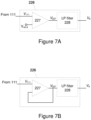
- Figure 7A schematically illustrates some components of the diagnostic voltage generator 226 according to an example, comprising an amplifier 227 having the signal line 111 coupled to its first input terminal and the output of the amplifier 227 coupled to its second input terminal with the amplifier 227.
- Figure 7B schematically illustrates some components of the diagnostic voltage generator 226 according to another example, comprising the amplifier 227 having the signal line 111 coupled to its first input terminal and a diagnostic reference voltage V ref,d coupled to its second input terminal.
- the scaling factor g d is larger than one and it may be referred to as a gain factor, whereas in another example the scaling factor g d is smaller than one and it may be referred to as an attenuation factor.
- the diagnostic voltage generator 226 may provide the output voltage V 227 as the diagnostic voltage V d or, optionally (as shown in the respective illustrations of Figures 7A and 7B ), the diagnostic voltage generator 226 may be arranged to apply a low pass filter 228 to the output voltage V 227 and provide the low-pass filtered output voltage as the diagnostic voltage V d .
- the parameters in the examples Figures 7A and 7B i.e. the scaling factor g d and the diagnostic reference voltage V ref,d (if applicable) are selected, in view of respective characteristics of the first and second resistors R 1 , R 2 , the high and low reference voltages V ref,high , V ref,low , the applied speed sensor 110 and/or the applied operating voltage V s such that a desired conversion from the signal voltage V 111 to the diagnostic voltage V d is provided to ensure suitable handling of the diagnostic signal 223 in the controller 230.
- the controller 230 may be arranged to compute the rotation speed and possibly also construct the digital speed signal based on the state indications 121 obtained from the state detector 220 in dependence of the diagnostic signal 223.
- the controller 230 may be arranged to determine, based on the diagnostic signal 223, whether the operational state of the speed measurement circuit 200 is normal or abnormal: in case the diagnostic signal 223 indicates the normal operational state, the controller 230 may proceed into computing the rotation speed and providing the speed indication 131 to indicate the computed rotation speed as described in the foregoing in context of the controller 130, whereas in case the diagnostic signal indicates an abnormal operational state, the controller 230 may issue an operational status indication 233 pertaining to an abnormal operational state of speed measurement circuit 200 identified based on the diagnostic signal 223.
- the controller 230 may, optionally, refrain from computing the rotation speed and/or providing the speed indication 131 due to possible malfunction appearing in the speed measurement circuit 200. Moreover, in case of the normal operational state, the controller 230 may optionally issue the operational status indication 233 as one pertaining to the normal operational state of the speed measurement circuit 200.
- the diagnostic signal 223 may be arranged to indicate one of one or more predefined abnormal operational states of the speed measurement circuit 200, such that the diagnostic value conveyed by the diagnostic signal 223, e.g. the diagnostic voltage V d , identifies the abnormal operational state.
- the abnormal operational states may involve two types thereof: in a first type of abnormal operational states the state indications 121 obtained from the state detector 220 (and/or the digital speed signal derived therefrom) indicate presence of one or more pulses or a pulse train but the diagnostic value conveyed by the diagnostic signal 223 reveals a failure in operation of the state detector 220 (e.g.
- the state indications 121 obtained from the state detector 220 (and/or the digital speed signal derived therefrom) do not indicate presence of a pulse train (which already serves as an indication of malfunction in the state detector 220) while the diagnostic value conveyed by the diagnostic signal 223 further confirms the failure in (e.g. electrical connections to or within) the state detector 220.
- the diagnostic signal 223 may provide the controller 230 with a time series of diagnostic values (e.g. one derived based on the time-varying diagnostic voltage V d ) that is descriptive of the operational state of speed measurement circuit 200 as a function of time and, consequently, the controller 230 may derive the operational status indication 233 based on one or more diagnostic values received in the diagnostic signal 223 (e.g. based on the diagnostic voltage V d at a given time instant or during a given time segment).
- the controller 230 may be arranged to derive the operational status indication 223 based on a time segment of the diagnostic signal 223 (e.g. based on the diagnostic voltage V d or changes therein during the time segment) having at least a predefined duration.
- the operational status indication 233 may comprise one of an indication of normal operational state of the speed measurement circuit 200 or an indication of abnormal operational state of the speed measurement circuit 200. Moreover, in case the operational status indication 233 reports abnormal operational state, the operational status indication 233 may further comprise an indication concerning characteristics of the abnormal operational state of the speed measurement circuit 200 derivable at the controller 230 based on the diagnostic signal 223, e.g. based on known predefined mapping between diagnostic values (e.g. diagnostic voltages V d ) and value ranges (e.g. the diagnostic voltage sub-ranges) corresponding to the abnormal operational states of the speed measurement circuit 200.
- diagnostic values e.g. diagnostic voltages V d
- value ranges e.g. the diagnostic voltage sub-ranges
- the operational status indication 233 issued by the controller 230 may be provided, for example, to a system controller to enable continuous monitoring of operation of the combustion engine, rotation speed of which the speed measurement circuit 200 serves to measure.
- the system controller may respond to an abnormal operational state of the speed measurement circuit 200 indicated via the operational status indication 233 by showing an alert or warning in this regard via a user interface (UI) and/or by storing an indication in this regard in a memory.
- the alert/warning shown via the UI and/or the indication stored in the memory may indicate presence of an abnormal operational state of the speed measurement circuit 200 and it may further comprise the indication concerning characteristics of the abnormal operational state of the speed measurement circuit 200.
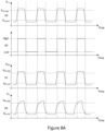
- Figure 8A schematically illustrates the relationship between the signal voltage V 111 received at the state detector 220, the pulse train derived in the controller 230, the output voltage V 227 of the amplifier 227, and the diagnostic voltage V d at the output of the (optional) low pass filter 228 according to an example.
- the illustrations (a) and (b) are the same ones already described with references to Figure 3 .
- the illustration (c) depicts the output voltage V 227 of the amplifier 227 as a function of time
- the illustration (d) depicts the diagnostic voltage V d as a function of time, where the diagnostic voltage V d is obtained by low pass filtering the output voltage V 227 .
- the output voltage V 227 (and the diagnostic voltage V d ) follows the envelope of the signal voltage V 111 , while the amplitude may be different due to scaling that may take place in the diagnostic voltage generator 226.
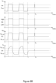
- Figure 8B schematically illustrates the relationship between the signal voltage V 111 received at the state detector 220 (the illustration (a)), the pulse train derived in the controller 230 (the illustration (b)), the output voltage V 227 of the amplifier 227 (the illustration (c)), and the diagnostic voltage V d at the output of the (optional) low pass filter 228 (the illustration (d)) according to another example.
- the first two pulses are similar to those of the corresponding illustrations of Figure 8A , whereas after the second pulse (at time instant t 1 ) a failure occurs in the speed measurement circuit 200, leading to a situation where the signal voltage V 111 is set to the voltage V err,2 and, consequently, resulting in the output voltage V 227 substantially immediately following the change in the signal voltage V 111 (possibly at different amplitude) and the diagnostic voltage V d following the change in the signal voltage V 111 (possibly at different amplitude) with a delay arising from operation of the low pass filter 228.
- this may serve as an indication of a failed electrical connection in the signal line 111 between the state detector 220 and the speed sensor 110 occurring at the time instant t 1 .
- the signal voltage V 111 may be caused for example by structural vibrations etc. momentarily restoring the electrical connection in the signal line 111 between the state detector 220 and the speed sensor 110.
- This may result in a short pulse in the pulse train derived in the controller 230 and result in the output voltage V 227 substantially immediately following the change in the signal voltage V 111 (possibly at different amplitude).
- the controller 230 is able to observe the following aspects from the output voltage V 227 (if provided as the diagnostic voltage V d ) and/or the from the diagnostic voltage V d :
- the controller 230 may be provided as an electrical circuit arranged to carry out the functionality described in the foregoing for the controller 230, by a processor provided with program instructions that cause the processor to carry out the functionality described in the foregoing for the controller 230, or by a combination of the two.
- a processor provided with program instructions that cause the processor to carry out the functionality described in the foregoing for the controller 230, or by a combination of the two.
- the reference(s) to a processor should not be understood to encompass only programmable processors, but also dedicated circuits such as field-programmable gate arrays (FPGA), application specific circuits (ASIC), etc.
- Figure 9 depicts a flowchart that illustrates steps of a method 300 that may be implemented by one or more circuits or apparatuses in order to provide the functionality described in the foregoing with references to the state detector 220 and/or to the controller 230.
- the method 300 may be varied in a number of ways, for example in accordance with the examples described in the foregoing and/or in the following.
- the method 300 serves to measure a rotation speed of a combustion engine and it proceeds from receiving, from the speed sensor 110 coupled to measure the rotation speed of the combustion engine, an electrical signal that has a time-varying signal voltage V 111 that exhibits local maxima at a frequency that has a predefined relationship to the rotation speed, as indicated in block 302.
- the method 300 further comprises deriving, based on the electrical signal, the state indication 121 that indicates whether the electrical signal represents one of a high state or a low state, as indicated in block 304, and deriving, based on the electrical signal, the diagnostic signal 223 that is descriptive of the operational state of the speed measurement circuit 220, as indicated in block 306.
- the method 300 further comprises deriving the rotation speed based on a time series of the state indications 121 in dependence of the diagnostic signal 223 in view of said predefined relationship, as indicated in block 308.
- the speed measurement circuit 200 and the method 300 serve to provide the state indication 121 separately from the diagnostic signal 223, it enables fast and accurate detection of the high/low state of the electrical signal received from the speed sensor 110 via the signal line 111 to enable calculation of the rotation speed in the controller 230 without a delay while at the same time providing diagnostics that enables identifying predefined failure conditions of the speed measurement circuit 200 in the course of its operation, thereby facilitating timely detection of incorrect speed measurement and an underlying failure condition.
Landscapes
- Engineering & Computer Science (AREA)
- Chemical & Material Sciences (AREA)
- Combustion & Propulsion (AREA)
- Mechanical Engineering (AREA)
- General Engineering & Computer Science (AREA)
- Control Of Electric Motors In General (AREA)
- Measurement Of Current Or Voltage (AREA)
Claims (13)
- Drehzahlmessschaltung (200) zum Messen einer Drehzahl eines Verbrennungsmotors, wobei die Drehzahlmessschaltung (200) Folgendes umfasst:einen Zustandsdetektor (220), der zwischen einer Betriebsspannung (V s) und einem Erdungspotential (V GND) gekoppelt ist und gekoppelt ist, um von einem Drehzahlsensor (110) ein elektrisches Signal zu empfangen, das eine zeitabhängige Signalspannung (V 111) aufweist, die lokale Maxima bei einer Frequenz aufweist, die eine vordefinierte Beziehung zur Drehzahl hat, wobei der Zustandsdetektor (220) angeordnet ist, um basierend auf dem elektrischen Signal Folgendes abzuleiten,eine Zustandsanzeige (121), die angibt, ob das elektrische Signal einen hohen oder einen niedrigen Zustand darstellt, undein Diagnosesignal (223), das den Betriebszustand der Drehzahlmessschaltung (220) beschreibt, wobei das Diagnosesignal (223) einen Diagnosewert übermittelt, der den aktuellen Betriebszustand der Drehzahlmessschaltung (200) beschreibt, wobei der aktuelle Betriebszustand ein normaler oder ein abnormaler Betriebszustand ist und wobei der Zustandsdetektor (220) so angeordnet ist, dass er den Diagnosewert basierend auf der Signalspannung (V 111) des elektrischen Signals ableitet; unddadurch gekennzeichnet, dass die Drehzahlmessschaltung (200) einen Controller (230) umfasst, der gekoppelt ist, um die Zustandsanzeigen (121) und das Diagnosesignal (223) zu empfangen, und der angeordnet ist, um die Drehzahl basierend auf einer Zeitreihe der Zustandsanzeigen (121) in Abhängigkeit des Diagnosesignals (223) im Hinblick auf die vordefinierte Beziehung zu berechnen,wobei der Zustandsdetektor (220) dafür definiert hat:zwei oder mehr vordefinierte Signalspannungsunterbereiche, die jeweils einem jeweiligen abnormalen Betriebszustand der Drehzahlmessschaltung (200) zugeordnet sind, undzwei oder mehr vordefinierte Zwischendiagnosespannungsunterbereiche, die jeweils einen jeweiligen abnormalen Betriebszustand der Drehzahlmessschaltung (200) darstellen.
- Drehzahlmessschaltung (200) nach Anspruch 1, wobei der Diagnosewert eines der folgenden anzeigt:einen normalen Betriebszustand der Drehzahlmessschaltung (200),einen von zwei oder mehr vordefinierten abnormalen Betriebszuständen der Drehzahlmessschaltung (200).
- Drehzahlmessschaltung (200) nach Anspruch 1 oder 2, wobei der Zustandsdetektor (220) dazu eingerichtet ist, die Signalspannung (V 111), die in einen vordefinierten Signalspannungsunterbereich fällt, der einem jeweiligen anormalen Betriebszustand zugeordnet ist, in einen Diagnosewert umzuwandeln, der in einem vordefinierten Zwischendiagnosespannungsunterbereich liegt, der den jeweiligen anormalen Betriebszustand darstellt.
- Drehzahlmessschaltung (200) nach einem der Ansprüche 1 bis 3, wobei der Zustandsdetektor (220) dafür definiert hat:einen hohen Signalspannungsunterbereich, der mit einem normalen Betriebszustand der Drehzahlmessschaltung (200) verbunden ist, und einen hohen Diagnosespannungsunterbereich, der den normalen Betriebszustand der Drehzahlmessschaltung (200) darstellt,einen niedrigen Signalspannungsunterbereich, der mit dem normalen Betriebszustand der Drehzahlmessschaltung (200) verbunden ist, und einen niedrigen Diagnosespannungsunterbereich, der den normalen Betriebszustand der Drehzahlmessschaltung (200) darstellt.
- Drehzahlmessschaltung (200) nach Anspruch 4, wobei der Zustandsdetektor (220) dazu eingerichtet ist, die Signalspannung (V 111), die in einen vordefinierten Signalspannungsunterbereich fällt, der einem normalen Betriebszustand zugeordnet ist, in einen Diagnosewert umzuwandeln, der innerhalb eines Diagnosespannungsunterbereichs liegt, der den normalen Betriebszustand darstellt.
- Drehzahlmessschaltung (200) nach Anspruch 1 oder 5, wobei der Diagnosewert eine Diagnosespannung (V d) umfasst und wobei der Zustandsdetektor (220) einen Diagnosespannungsgenerator (226) umfasst, der dazu eingerichtet ist, die Diagnosespannung (V d) auf Grundlage der aktuellen Signalspannung (V 111) des elektrischen Signals abzuleiten.
- Drehzahlmessschaltung (200) nach Anspruch 6, wobei der Diagnosespannungsgenerator (226) einen Verstärker (227) zum Skalieren des elektrischen Signals zum Ableiten des Diagnosesignals (223) umfasst.
- Drehzahlmessschaltung (200) nach Anspruch 7, wobei der Diagnosespannungsgenerator (226) einen Tiefpassfilter (228) zum Filtern des skalierten elektrischen Signals umfasst, das vom Verstärker (227) erhalten wird.
- Drehzahlmessschaltung (200) nach einem der Ansprüche 1 bis 8, wobei die anormalen Betriebszustände der Drehzahlmessschaltung (200) einen oder mehrere der folgenden umfassen:einen ersten anormalen Betriebszustand, der eine fehlerhafte elektrische Verbindung zwischen dem Erdpotential (V GND) und dem Drehzahlsensor (110) darstellt,einen zweiten anormalen Betriebszustand, der eine fehlerhafte elektrische Verbindung zwischen dem Zustandsdetektor (220) und dem Drehzahlsensor (110) darstellt,einen dritten anormalen Betriebszustand, der eine fehlerhafte elektrische Verbindung zwischen der Betriebsspannung (V s) und dem Drehzahlsensor (110) darstellt,
- Drehzahlmessschaltung (200) nach einem der Ansprüche 1 bis 9, wobei die Steuerung (230) dazu eingerichtet ist, mindestens eine der folgenden auszuführen:Bereitstellen einer Geschwindigkeitsanzeige (131) als Reaktion auf das Diagnosesignal (223), das einen normalen Betriebszustand der Drehzahlmessschaltung (200) anzeigt,Unterlassen der Bereitstellung der Geschwindigkeitsanzeige (131) als Reaktion auf das Diagnosesignal (223), das einen abnormalen Betriebszustand der Drehzahlmessschaltung (200) anzeigt.
- Drehzahlmessschaltung (200) nach Anspruch 10, wobei das Berechnen der Drehzahl einen der folgenden umfasst:Berechnen der Drehzahl basierend auf einer jeweiligen Frequenz von Änderungen vom hohen Zustand zum niedrigen Zustand und/oder vom niedrigen Zustand zum hohen Zustand, die in der Zeitreihe von Zustandsanzeigen (121) im Hinblick auf die vordefinierte Beziehung angegeben sind,Ableiten eines digitalen Drehzahlsignals, das eine Impulsfolge umfasst, die basierend auf der Zeitreihe von Zustandsanzeigen (121) abgeleitet ist, undBerechnen der Drehzahl basierend auf einer Impulsfrequenz der Impulsfolge im Hinblick auf die vordefinierte Beziehung.
- Drehzahlmessschaltung (200) nach einem der Ansprüche 1 bis 11, wobei die Steuerung (230) so angeordnet ist, dass sie mindestens eine der folgenden ausführt:Ableiten einer Betriebsstatusanzeige (233), die einen normalen Betriebszustand der Drehzahlmessschaltung (200) anzeigt, als Reaktion auf das Diagnosesignal (223), das einen normalen Betriebszustand der Drehzahlmessschaltung (200) anzeigt,Ableiten einer Betriebsstatusanzeige (233), die einen abnormalen Betriebszustand der Drehzahlmessschaltung (200) anzeigt, und Identifizieren eines abnormalen Betriebszustands, der durch das Diagnosesignal (223) angezeigt wird, als Reaktion auf das Diagnosesignal (223), das einen abnormalen Betriebszustand der Drehzahlmessschaltung (200) anzeigt.
- Verfahren (300) zum Messen einer Drehzahl eines Verbrennungsmotors durch Verwendung einer Drehzahlmessschaltung (300), wobei das Verfahren (300) Folgendes umfasst:Empfangen (302) eines elektrischen Signals von einem Drehzahlsensor (110), der zum Messen der Drehzahl gekoppelt ist, mit einer zeitlich variierenden Signalspannung (V 111), die lokale Maxima bei einer Frequenz aufweist, die in einer vordefinierten Beziehung zur Drehzahl steht;Ableiten (304) einer Zustandsanzeige (121), basierend auf dem elektrischen Signal, die angibt, ob das elektrische Signal einen hohen oder einen niedrigen Zustand darstellt;Ableiten (306) eines Diagnosesignals (223), basierend auf dem elektrischen Signal, das den Betriebszustand der Drehzahlmessschaltung (220) beschreibt, wobei das Diagnosesignal (223) einen Diagnosewert übermittelt,der den aktuellen Betriebszustand der Drehzahlmessschaltung (200) beschreibt, wobei der aktuelle Betriebszustand ein normaler oder ein abnormaler Betriebszustand ist und wobei der Diagnosewert basierend auf der Signalspannung (V 111) des elektrischen Signals abgeleitet wird; unddadurch gekennzeichnet, dass das Verfahren (300) das Ableiten (308) der Drehzahl auf der Grundlage einer Zeitreihe der Zustandsanzeigen (121) in Abhängigkeit des Diagnosesignals (223) im Hinblick auf die vordefinierte Beziehung umfasst,wobei der Diagnosewert durch Anwendung des Folgenden abgeleitet wird:zwei oder mehr vordefinierte Signalspannungsunterbereiche, die jeweils einem jeweiligen abnormalen Betriebszustand der Drehzahlmessschaltung (200) zugeordnet sind, undzwei oder mehr vordefinierte Zwischendiagnosespannungsunterbereiche, die jeweils einen jeweiligen abnormalen Betriebszustand der Drehzahlmessschaltung (200) darstellen.
Applications Claiming Priority (1)
| Application Number | Priority Date | Filing Date | Title |
|---|---|---|---|
| PCT/FI2020/050252 WO2021209677A1 (en) | 2020-04-17 | 2020-04-17 | An engine speed measurement circuit |
Publications (2)
| Publication Number | Publication Date |
|---|---|
| EP4136335A1 EP4136335A1 (de) | 2023-02-22 |
| EP4136335B1 true EP4136335B1 (de) | 2025-02-26 |
Family
ID=70465112
Family Applications (1)
| Application Number | Title | Priority Date | Filing Date |
|---|---|---|---|
| EP20721670.6A Active EP4136335B1 (de) | 2020-04-17 | 2020-04-17 | Schaltung zur messung der drehzahl eines motors |
Country Status (4)
| Country | Link |
|---|---|
| EP (1) | EP4136335B1 (de) |
| KR (1) | KR102665010B1 (de) |
| CN (1) | CN115398087B (de) |
| WO (1) | WO2021209677A1 (de) |
Families Citing this family (2)
| Publication number | Priority date | Publication date | Assignee | Title |
|---|---|---|---|---|
| KR102938117B1 (ko) * | 2024-01-05 | 2026-03-12 | 주식회사 플렉스시스템 | 발사체 터보펌프 회전속도 측정장치 및 방법 |
| CN119435220B (zh) * | 2024-09-30 | 2025-10-24 | 潍柴动力股份有限公司 | 一种发动机同步的判断方法、装置、设备和存储介质 |
Family Cites Families (11)
| Publication number | Priority date | Publication date | Assignee | Title |
|---|---|---|---|---|
| CA1130889A (en) * | 1978-05-08 | 1982-08-31 | Chun-Keung Leung | Integrated engine control system |
| JPH0826801B2 (ja) * | 1987-11-13 | 1996-03-21 | 澤藤電機株式会社 | 回転制御装置 |
| JPH0614087B2 (ja) * | 1989-02-13 | 1994-02-23 | 日本電装株式会社 | センサ信号の処理装置 |
| US5140961A (en) * | 1990-01-12 | 1992-08-25 | Nissan Motor Co., Ltd. | System and method for self diagnosing an engine control system |
| DE59801550D1 (de) * | 1997-11-20 | 2001-10-25 | Siemens Ag | Diagnoseeinrichtung zur erkennung von kurzschlüssen oder leitungsunterbrechungen eines induktiven sensors |
| KR100412881B1 (ko) * | 2001-10-06 | 2003-12-31 | 현대자동차주식회사 | 엔진제어장치의 엔진회전수 출력 자기진단 방법 |
| KR101037236B1 (ko) * | 2003-02-07 | 2011-05-25 | 로베르트 보쉬 게엠베하 | 센서를 위한 진단 방법 |
| JP5505337B2 (ja) * | 2011-03-02 | 2014-05-28 | 株式会社デンソー | エンジン始動制御装置 |
| DE102013207173A1 (de) * | 2013-04-19 | 2014-10-23 | Robert Bosch Gmbh | Verfahren zur Bestimmung von Segmentzeiten eines Geberrads eines Verbrennungsmotors |
| JP6222020B2 (ja) * | 2014-09-09 | 2017-11-01 | トヨタ自動車株式会社 | 空燃比センサの異常診断装置 |
| FR3035157B1 (fr) * | 2015-04-16 | 2017-04-21 | Continental Automotive France | Procede et dispositif de detection de rotation inverse d'un moteur a combustion interne |
-
2020
- 2020-04-17 EP EP20721670.6A patent/EP4136335B1/de active Active
- 2020-04-17 CN CN202080099848.8A patent/CN115398087B/zh active Active
- 2020-04-17 KR KR1020227039665A patent/KR102665010B1/ko active Active
- 2020-04-17 WO PCT/FI2020/050252 patent/WO2021209677A1/en not_active Ceased
Also Published As
| Publication number | Publication date |
|---|---|
| EP4136335A1 (de) | 2023-02-22 |
| KR20220164604A (ko) | 2022-12-13 |
| CN115398087B (zh) | 2024-08-23 |
| KR102665010B1 (ko) | 2024-05-10 |
| CN115398087A (zh) | 2022-11-25 |
| WO2021209677A1 (en) | 2021-10-21 |
Similar Documents
| Publication | Publication Date | Title |
|---|---|---|
| EP2067088B1 (de) | Diagnose für zwei-draht prozess-regelschleife | |
| EP4136335B1 (de) | Schaltung zur messung der drehzahl eines motors | |
| US6845468B2 (en) | Aircraft fault monitoring system and method | |
| EP2609408B1 (de) | Messung der temperatur einer prozessflüssigkeit | |
| US9343896B2 (en) | Safety circuit arrangement and method for the fail-safe monitoring of a movement variable | |
| EP1850137B1 (de) | Vorrichtung zum Messen von Rotationspositionen | |
| JP5163963B2 (ja) | 異常監視装置 | |
| JP2012149999A (ja) | 自己診断可能な電子回路及び磁界検出装置 | |
| JP6329648B2 (ja) | 故障検出装置 | |
| US20190293675A1 (en) | Rotary speed sensors | |
| RU2313099C2 (ru) | Устройство для определения частоты вращения вращающейся детали машины | |
| US9519565B2 (en) | Method for automatically monitoring at least one component of a physical system | |
| EP1500026B1 (de) | Fehlertolerante vorrichtung und verfahren zur bestimmung einer umdrehungsgeschwindigkeit eines zahnrads | |
| CN103869142B (zh) | 用于监视信号电平的方法和设备 | |
| US7248991B2 (en) | Method and device for detecting a rotational speed, especially the rotational speed of the wheel of a vehicle | |
| EP2921922B1 (de) | Verfahren und Vorrichtung zur Überwachung eines Signals | |
| CN116221386B (zh) | 一种电控换档系统位置信号校验方法、装置及存储介质 | |
| EP1744169A2 (de) | Mittel zur Fehlerdetektion in Generatoren | |
| CN116908731A (zh) | 数字式超声波电源工作异常判断方法 | |
| JP6276677B2 (ja) | 標準信号発生器 | |
| US11262405B2 (en) | Fault detection in a multi-phase electric machine | |
| JP6946914B2 (ja) | 電子制御装置 | |
| CN120559425A (zh) | 一种电调mos短路检测的方法及系统 | |
| CN121382333A (zh) | 汽轮机转速实时采集方法及系统 | |
| CN116868031A (zh) | 用于识别对传感器单元的操纵的方法 |
Legal Events
| Date | Code | Title | Description |
|---|---|---|---|
| STAA | Information on the status of an ep patent application or granted ep patent |
Free format text: STATUS: UNKNOWN |
|
| STAA | Information on the status of an ep patent application or granted ep patent |
Free format text: STATUS: THE INTERNATIONAL PUBLICATION HAS BEEN MADE |
|
| PUAI | Public reference made under article 153(3) epc to a published international application that has entered the european phase |
Free format text: ORIGINAL CODE: 0009012 |
|
| STAA | Information on the status of an ep patent application or granted ep patent |
Free format text: STATUS: REQUEST FOR EXAMINATION WAS MADE |
|
| 17P | Request for examination filed |
Effective date: 20221114 |
|
| AK | Designated contracting states |
Kind code of ref document: A1 Designated state(s): AL AT BE BG CH CY CZ DE DK EE ES FI FR GB GR HR HU IE IS IT LI LT LU LV MC MK MT NL NO PL PT RO RS SE SI SK SM TR |
|
| DAV | Request for validation of the european patent (deleted) | ||
| DAX | Request for extension of the european patent (deleted) | ||
| GRAP | Despatch of communication of intention to grant a patent |
Free format text: ORIGINAL CODE: EPIDOSNIGR1 |
|
| STAA | Information on the status of an ep patent application or granted ep patent |
Free format text: STATUS: GRANT OF PATENT IS INTENDED |
|
| INTG | Intention to grant announced |
Effective date: 20241113 |
|
| RAP3 | Party data changed (applicant data changed or rights of an application transferred) |
Owner name: WAERTSILAE FINLAND OY |
|
| GRAS | Grant fee paid |
Free format text: ORIGINAL CODE: EPIDOSNIGR3 |
|
| GRAA | (expected) grant |
Free format text: ORIGINAL CODE: 0009210 |
|
| STAA | Information on the status of an ep patent application or granted ep patent |
Free format text: STATUS: THE PATENT HAS BEEN GRANTED |
|
| AK | Designated contracting states |
Kind code of ref document: B1 Designated state(s): AL AT BE BG CH CY CZ DE DK EE ES FI FR GB GR HR HU IE IS IT LI LT LU LV MC MK MT NL NO PL PT RO RS SE SI SK SM TR |
|
| REG | Reference to a national code |
Ref country code: GB Ref legal event code: FG4D |
|
| REG | Reference to a national code |
Ref country code: CH Ref legal event code: EP |
|
| REG | Reference to a national code |
Ref country code: DE Ref legal event code: R096 Ref document number: 602020046717 Country of ref document: DE |
|
| REG | Reference to a national code |
Ref country code: IE Ref legal event code: FG4D |
|
| REG | Reference to a national code |
Ref country code: NL Ref legal event code: MP Effective date: 20250226 |
|
| PG25 | Lapsed in a contracting state [announced via postgrant information from national office to epo] |
Ref country code: RS Free format text: LAPSE BECAUSE OF FAILURE TO SUBMIT A TRANSLATION OF THE DESCRIPTION OR TO PAY THE FEE WITHIN THE PRESCRIBED TIME-LIMIT Effective date: 20250526 |
|
| PG25 | Lapsed in a contracting state [announced via postgrant information from national office to epo] |
Ref country code: FI Free format text: LAPSE BECAUSE OF FAILURE TO SUBMIT A TRANSLATION OF THE DESCRIPTION OR TO PAY THE FEE WITHIN THE PRESCRIBED TIME-LIMIT Effective date: 20250226 |
|
| PG25 | Lapsed in a contracting state [announced via postgrant information from national office to epo] |
Ref country code: PL Free format text: LAPSE BECAUSE OF FAILURE TO SUBMIT A TRANSLATION OF THE DESCRIPTION OR TO PAY THE FEE WITHIN THE PRESCRIBED TIME-LIMIT Effective date: 20250226 |
|
| PGFP | Annual fee paid to national office [announced via postgrant information from national office to epo] |
Ref country code: DE Payment date: 20250422 Year of fee payment: 6 |
|
| PG25 | Lapsed in a contracting state [announced via postgrant information from national office to epo] |
Ref country code: ES Free format text: LAPSE BECAUSE OF FAILURE TO SUBMIT A TRANSLATION OF THE DESCRIPTION OR TO PAY THE FEE WITHIN THE PRESCRIBED TIME-LIMIT Effective date: 20250226 |
|
| REG | Reference to a national code |
Ref country code: LT Ref legal event code: MG9D |
|
| PG25 | Lapsed in a contracting state [announced via postgrant information from national office to epo] |
Ref country code: NO Free format text: LAPSE BECAUSE OF FAILURE TO SUBMIT A TRANSLATION OF THE DESCRIPTION OR TO PAY THE FEE WITHIN THE PRESCRIBED TIME-LIMIT Effective date: 20250526 Ref country code: IS Free format text: LAPSE BECAUSE OF FAILURE TO SUBMIT A TRANSLATION OF THE DESCRIPTION OR TO PAY THE FEE WITHIN THE PRESCRIBED TIME-LIMIT Effective date: 20250626 |
|
| PG25 | Lapsed in a contracting state [announced via postgrant information from national office to epo] |
Ref country code: NL Free format text: LAPSE BECAUSE OF FAILURE TO SUBMIT A TRANSLATION OF THE DESCRIPTION OR TO PAY THE FEE WITHIN THE PRESCRIBED TIME-LIMIT Effective date: 20250226 |
|
| PG25 | Lapsed in a contracting state [announced via postgrant information from national office to epo] |
Ref country code: HR Free format text: LAPSE BECAUSE OF FAILURE TO SUBMIT A TRANSLATION OF THE DESCRIPTION OR TO PAY THE FEE WITHIN THE PRESCRIBED TIME-LIMIT Effective date: 20250226 |
|
| PG25 | Lapsed in a contracting state [announced via postgrant information from national office to epo] |
Ref country code: PT Free format text: LAPSE BECAUSE OF FAILURE TO SUBMIT A TRANSLATION OF THE DESCRIPTION OR TO PAY THE FEE WITHIN THE PRESCRIBED TIME-LIMIT Effective date: 20250626 Ref country code: LV Free format text: LAPSE BECAUSE OF FAILURE TO SUBMIT A TRANSLATION OF THE DESCRIPTION OR TO PAY THE FEE WITHIN THE PRESCRIBED TIME-LIMIT Effective date: 20250226 |
|
| PG25 | Lapsed in a contracting state [announced via postgrant information from national office to epo] |
Ref country code: BG Free format text: LAPSE BECAUSE OF FAILURE TO SUBMIT A TRANSLATION OF THE DESCRIPTION OR TO PAY THE FEE WITHIN THE PRESCRIBED TIME-LIMIT Effective date: 20250226 Ref country code: GR Free format text: LAPSE BECAUSE OF FAILURE TO SUBMIT A TRANSLATION OF THE DESCRIPTION OR TO PAY THE FEE WITHIN THE PRESCRIBED TIME-LIMIT Effective date: 20250527 |
|
| PGFP | Annual fee paid to national office [announced via postgrant information from national office to epo] |
Ref country code: AT Payment date: 20250423 Year of fee payment: 6 |
|
| PG25 | Lapsed in a contracting state [announced via postgrant information from national office to epo] |
Ref country code: SE Free format text: LAPSE BECAUSE OF FAILURE TO SUBMIT A TRANSLATION OF THE DESCRIPTION OR TO PAY THE FEE WITHIN THE PRESCRIBED TIME-LIMIT Effective date: 20250226 |
|
| PG25 | Lapsed in a contracting state [announced via postgrant information from national office to epo] |
Ref country code: SM Free format text: LAPSE BECAUSE OF FAILURE TO SUBMIT A TRANSLATION OF THE DESCRIPTION OR TO PAY THE FEE WITHIN THE PRESCRIBED TIME-LIMIT Effective date: 20250226 |
|
| PG25 | Lapsed in a contracting state [announced via postgrant information from national office to epo] |
Ref country code: DK Free format text: LAPSE BECAUSE OF FAILURE TO SUBMIT A TRANSLATION OF THE DESCRIPTION OR TO PAY THE FEE WITHIN THE PRESCRIBED TIME-LIMIT Effective date: 20250226 |
|
| PG25 | Lapsed in a contracting state [announced via postgrant information from national office to epo] |
Ref country code: IT Free format text: LAPSE BECAUSE OF FAILURE TO SUBMIT A TRANSLATION OF THE DESCRIPTION OR TO PAY THE FEE WITHIN THE PRESCRIBED TIME-LIMIT Effective date: 20250226 |
|
| PG25 | Lapsed in a contracting state [announced via postgrant information from national office to epo] |
Ref country code: EE Free format text: LAPSE BECAUSE OF FAILURE TO SUBMIT A TRANSLATION OF THE DESCRIPTION OR TO PAY THE FEE WITHIN THE PRESCRIBED TIME-LIMIT Effective date: 20250226 Ref country code: CZ Free format text: LAPSE BECAUSE OF FAILURE TO SUBMIT A TRANSLATION OF THE DESCRIPTION OR TO PAY THE FEE WITHIN THE PRESCRIBED TIME-LIMIT Effective date: 20250226 |
|
| PG25 | Lapsed in a contracting state [announced via postgrant information from national office to epo] |
Ref country code: RO Free format text: LAPSE BECAUSE OF FAILURE TO SUBMIT A TRANSLATION OF THE DESCRIPTION OR TO PAY THE FEE WITHIN THE PRESCRIBED TIME-LIMIT Effective date: 20250226 |
|
| PG25 | Lapsed in a contracting state [announced via postgrant information from national office to epo] |
Ref country code: SK Free format text: LAPSE BECAUSE OF FAILURE TO SUBMIT A TRANSLATION OF THE DESCRIPTION OR TO PAY THE FEE WITHIN THE PRESCRIBED TIME-LIMIT Effective date: 20250226 |
|
| REG | Reference to a national code |
Ref country code: CH Ref legal event code: H13 Free format text: ST27 STATUS EVENT CODE: U-0-0-H10-H13 (AS PROVIDED BY THE NATIONAL OFFICE) Effective date: 20251125 |
|
| REG | Reference to a national code |
Ref country code: DE Ref legal event code: R097 Ref document number: 602020046717 Country of ref document: DE |
|
| PG25 | Lapsed in a contracting state [announced via postgrant information from national office to epo] |
Ref country code: LU Free format text: LAPSE BECAUSE OF NON-PAYMENT OF DUE FEES Effective date: 20250417 |
|
| PG25 | Lapsed in a contracting state [announced via postgrant information from national office to epo] |
Ref country code: MC Free format text: LAPSE BECAUSE OF FAILURE TO SUBMIT A TRANSLATION OF THE DESCRIPTION OR TO PAY THE FEE WITHIN THE PRESCRIBED TIME-LIMIT Effective date: 20250226 |
|
| REG | Reference to a national code |
Ref country code: BE Ref legal event code: MM Effective date: 20250430 |
|
| PLBE | No opposition filed within time limit |
Free format text: ORIGINAL CODE: 0009261 |
|
| STAA | Information on the status of an ep patent application or granted ep patent |
Free format text: STATUS: NO OPPOSITION FILED WITHIN TIME LIMIT |
|
| PG25 | Lapsed in a contracting state [announced via postgrant information from national office to epo] |
Ref country code: FR Free format text: LAPSE BECAUSE OF NON-PAYMENT OF DUE FEES Effective date: 20250426 |
|
| PG25 | Lapsed in a contracting state [announced via postgrant information from national office to epo] |
Ref country code: BE Free format text: LAPSE BECAUSE OF NON-PAYMENT OF DUE FEES Effective date: 20250430 |
|
| PG25 | Lapsed in a contracting state [announced via postgrant information from national office to epo] |
Ref country code: CH Free format text: LAPSE BECAUSE OF NON-PAYMENT OF DUE FEES Effective date: 20250430 |
|
| GBPC | Gb: european patent ceased through non-payment of renewal fee |
Effective date: 20250526 |
|
| 26N | No opposition filed |
Effective date: 20251127 |
|
| PG25 | Lapsed in a contracting state [announced via postgrant information from national office to epo] |
Ref country code: GB Free format text: LAPSE BECAUSE OF NON-PAYMENT OF DUE FEES Effective date: 20250526 |
|
| PG25 | Lapsed in a contracting state [announced via postgrant information from national office to epo] |
Ref country code: IE Free format text: LAPSE BECAUSE OF NON-PAYMENT OF DUE FEES Effective date: 20250417 |