EP1500026B1 - Fehlertolerante vorrichtung und verfahren zur bestimmung einer umdrehungsgeschwindigkeit eines zahnrads - Google Patents
Fehlertolerante vorrichtung und verfahren zur bestimmung einer umdrehungsgeschwindigkeit eines zahnrads Download PDFInfo
- Publication number
- EP1500026B1 EP1500026B1 EP03733919.9A EP03733919A EP1500026B1 EP 1500026 B1 EP1500026 B1 EP 1500026B1 EP 03733919 A EP03733919 A EP 03733919A EP 1500026 B1 EP1500026 B1 EP 1500026B1
- Authority
- EP
- European Patent Office
- Prior art keywords
- pulse
- input
- edge
- signal
- memory
- Prior art date
- Legal status (The legal status is an assumption and is not a legal conclusion. Google has not performed a legal analysis and makes no representation as to the accuracy of the status listed.)
- Expired - Lifetime
Links
- 238000000034 method Methods 0.000 title claims description 23
- 230000007704 transition Effects 0.000 claims description 46
- 230000001934 delay Effects 0.000 claims description 17
- 230000003044 adaptive effect Effects 0.000 claims description 14
- 238000001914 filtration Methods 0.000 claims description 2
- 238000005259 measurement Methods 0.000 description 38
- 230000008569 process Effects 0.000 description 13
- 238000010586 diagram Methods 0.000 description 10
- 230000004044 response Effects 0.000 description 7
- 239000003990 capacitor Substances 0.000 description 5
- 230000010355 oscillation Effects 0.000 description 5
- 238000005070 sampling Methods 0.000 description 5
- 230000000630 rising effect Effects 0.000 description 4
- 230000001052 transient effect Effects 0.000 description 4
- 230000008859 change Effects 0.000 description 3
- 238000002955 isolation Methods 0.000 description 3
- 238000012935 Averaging Methods 0.000 description 1
- 230000005355 Hall effect Effects 0.000 description 1
- 238000004458 analytical method Methods 0.000 description 1
- 230000008901 benefit Effects 0.000 description 1
- 230000001143 conditioned effect Effects 0.000 description 1
- 230000003750 conditioning effect Effects 0.000 description 1
- 238000010276 construction Methods 0.000 description 1
- 238000003708 edge detection Methods 0.000 description 1
- 230000004907 flux Effects 0.000 description 1
- 238000010248 power generation Methods 0.000 description 1
- 238000011112 process operation Methods 0.000 description 1
- 230000008439 repair process Effects 0.000 description 1
- 230000001960 triggered effect Effects 0.000 description 1
Images





Classifications
-
- G—PHYSICS
- G01—MEASURING; TESTING
- G01P—MEASURING LINEAR OR ANGULAR SPEED, ACCELERATION, DECELERATION, OR SHOCK; INDICATING PRESENCE, ABSENCE, OR DIRECTION, OF MOVEMENT
- G01P3/00—Measuring linear or angular speed; Measuring differences of linear or angular speeds
- G01P3/42—Devices characterised by the use of electric or magnetic means
- G01P3/44—Devices characterised by the use of electric or magnetic means for measuring angular speed
- G01P3/48—Devices characterised by the use of electric or magnetic means for measuring angular speed by measuring frequency of generated current or voltage
- G01P3/481—Devices characterised by the use of electric or magnetic means for measuring angular speed by measuring frequency of generated current or voltage of pulse signals
- G01P3/489—Digital circuits therefor
Definitions
- the invention relates generally to highly accurate measurements and more particularly to a fault tolerant system and method for accurately determining a revolution rate of a rotating gear.
- Known measurement systems can measure the revolution rate of a rotating gear based on the elapsed time for a point on the gear to pass over a sensor during a complete rotation.
- a rotating gear can be, for example, a turbine or compressor.
- transient noise if not properly rejected can cause measurement errors.
- transient noise can be introduced into the measurement system, for example, low amplitude or slow input signals; electromagnetic compatibility (EMC) transients; or modular hot inserts or spare removals.
- EMC electromagnetic compatibility
- power surges if not properly addressed can cause the measurement system to fail.
- any sensor failure e.g. relating to a broken sensor or broken wire to the sensor should be detected quickly so that repairs can be made and the proper performance of the measurement system is assured.
- German patent document DE 3925889 describes a system for calculating the wheel speed of a motor vehicle by using a toothed rotor.
- a measurement system comprises an edge detector, a memory and a pulse-input engine.
- the edge detector receives an input signal having pulses corresponding to the teeth of a rotating gear being measured.
- the edge detector also receives a counter signal.
- the edge detector detects edge transitions form the input signal and sends a set of time values based on the input signal and the counter signal. Each time value from the set of time values is uniquely associated with the detected edge transition from the input signal.
- the memory receives from the edge detector the set of time values, and stores the set of time values.
- the pulse-input engine calculates a set of pulse-to-pulse delays based on the set of time values stored in the memory.
- a set of main processors can then calculate revolutions per minute (RPM) of the measured gear based on the pulse-to-pulse delays.
- RPM revolutions per minute
- the measurement system is a triple redundant system having three independent input channels within the pulse-input module each being uniquely associated with one of three main processors.
- the three input channels can operate in parallel and isolated from each other. Thus, if a hardware failure occurs on one channel, the other channels can override it.
- the faulting module can be easily removed and replace without interrupting the operation of the remaining modules.
- the three main processors can use a two-out-of-three voting to provide high-integrity error-free, uninterrupted process operations without a single point of failure.
- FIG. 1 shows a system block diagram of a measurement system, according to an embodiment of the invention.
- measurement system 100 includes sensor 110, baseplate 120, pulse-input module 130, triplicate input/output (I/O) bus 140, main processors 150, 160 and 170 and input device 180.
- Pulse-input module 130 includes a set of pulse-input legs 132 and a set of I/O controllers 135.
- Each I/O controller 135 includes pulse-input application specific integrate circuit (ASIC) 137 and isolated bus transceiver 138.
- Sensor 110 is coupled to baseplate 120, which is coupled to pulse-input module 130.
- Pulse-input module 130 is coupled to triplicate I/O bus 140, which is coupled to main processors 150, 160 and 170.
- ASIC application specific integrate circuit
- Sensor 110 measures the rotation of an adjacently disposed rotating gear.
- Sensor 110 can be, for example, a passive magnetic sensor or an active speed sensor.
- a passive magnetic sensor can have, for example, a permanent magnet wrapped with a coil of wire. Any change in inductance at the sensor input produces a change in flux and results in an output voltage. The output of such a magnetic type of sensor is proportional to the speed of and proximity to the teeth of the rotating gear.
- An active speed sensor can have, for example, a power source and Hall Effect sensors, and output a ground-referenced signal.
- Such an active speed sensor can include a power supply, for example, a 5V, 12V or 24V, etc. power supply appropriate for the particular active speed sensor.
- the measurement system can be configured to monitor the functioning of the power supply.
- Baseplate 120 provides the field connections of power and I/O for the sensor 110, and connects sensor 110 to the pulse-input module 130.
- Baseplate 120 can have a network of headers, jumpers and resistors so that any of the various types of sensors can be coupled to the base-plate 120 and operable with pulse-input module 130.
- Pulse-input module 130 receives a signal from the sensor 110 through the baseplate 120.
- the received signal indicates the voltage transitions from the sensor 110 and corresponds to gear teeth rotating in proximity of sensor 110. Every input transition is sampled and time is measured for an optimized number of input gear pulses. The resulting time values are used to generate pulse-to-pulse delays, which are provided to the main processors 150, 160 and 170 via triplicate I/O bus 140.
- pulse-input module 130 includes a set of independent input channels, each of which includes its own pulse-input leg 132 and I/O controller 135.
- the pulse-input module 130 can include three independent input channels A, B and C.
- Each of these three independent input channels A, B and C can include their own pulse-input leg 132, also referred to herein as pulse-input legs A, B and C, respectively, and their own I/O controllers 135, also referred to herein as I/O controllers A, B and C, respectively.
- Input device 180 receives sensor information from a user and provides that sensor information to the pulse-input module 130.
- the sensor information can include, for example, a sensor-type indication, a gear-teeth-number indication, an edge-type indication and/or a field-voltage indication if the sensor-type indication is an active sensor indication.
- the pulse-input module 130 can perform calculations that take into account the characteristics of the sensor 110 being measured. In particular, various calculations discussed below in reference to the pulse-input module 130 are based on, for example, the number of gear teeth, etc.
- the embodiments discussed herein refer to a triple redundant system (e.g., having three independent input channels within the pulse-input module each being uniquely associated with one of the three main processors), any number of subsystems is possible including just a single subsystem.
- the number of independent input channels within the pulse-input module and corresponding main processors can be one or more as appropriate for a given application. For application requiring a significant degree of safety and availability, such as power generation, at least triple redundancy is typically appropriate.
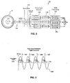
- FIG. 2 shows a gear and a portion of the measurement system shown in FIG. 1 .
- gear 10 is disposed adjacent to sensor 110 of measurement system 100.
- the rotation of gear 10 (shown in FIG. 2 in a clockwise manner) is measured by sensor 110, which provides a signal to baseplate 120.
- the baseplate 120 provides that signal to the three pulse-input legs 132 A, B and C, each of which includes a filter network that performs leg-to-leg isolation filtering, and a comparator network.
- Pulse-input legs 132 A, B and C, and I/O controllers 135 A, B and C respectively, independently calculate pulse-to-pulse delays and provide those values to main processors 140, 150 and 160, respectively.
- Main processors 140, 150 and 160 then collectively determine a voted pulse rate value, also referred herein as a voted measurement of the revolutions per minute (RPM).
- RPM revolutions per minute
- FIG. 3 shows an example of a signal produced by the sensor based on the gear shown in FIG. 2 .
- the signal 300 produced by sensor 110 is a sinusoidal signal that corresponds to four teeth of gear 10. These four teeth of gear 10 are labeled in FIG. 3 as 1 through 4.
- the signal 300 is provided from sensor 110 to pulse-input module 130, which detects the rising edges or trailing edges of the received signal. Each of these rising edges or trailing edges corresponds to a gear tooth rotating to a position adjacent to the sensor 110.
- FIG. 3 shows the case where the rising edges of the received signal are detected. More specifically, as the rising edge of signal 300 reaches the pulse trigger level 310, a pulse is generated. Thus, as the signal 300 reaches the pulse trigger level 310 for gear teeth 1 through 4, pulses 320, 330, 340 and 350, respectively, are generated.
- FIG. 4 shows a system block diagram of the pulse-input module shown in FIGS. 1 and 2 .
- the pulse-input module 130 includes pulse-input legs 132 and I/O controllers 135.
- Each pulse-input leg 132 includes a filter network 133 and comparator network 134.
- Each comparator network 134 includes a set of switches that allow comparator network 134 to receive a test-pulse signal from the zero-speed tester 740 (shown in FIG. 7 ).
- Each I/O controller 135 includes pulse-input ASIC 137 and isolated bus transceiver 139.
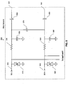
- FIG. 5 shows a system block diagram of the filter network of the pulse-input leg shown in FIG. 4 .
- the filter network 500 includes bi-directional transzorbs 510 and 520, resistors 530 and 540, and capacitors 550, 560, 570, 580 and 590.
- the filter network 500 receives the input voltage signals from base-plate 120 at points 501 and 502 and forwards the conditioned signals to the comparator network 600 (shown in FIG. 6 ) from points 591 and 592.
- the filter network 500 clamps the input voltages of the received signal, provides leg-to-leg isolation and filters the received signal. More specifically, the bi-directional transzorbs 510 and 520 clamps input noise and the electromagnetic compatibility (EMC) transients.
- the resistors 530 and 540 form a low pass filter and provide leg-to-leg isolation.
- the capacitors 560 through 590 perform signal conditioning.
- the bi-directional transzorbs 510 and 520 are 36 V transzorbs and the resistors 530 and 540 each have 15 K ohm resistance. In other embodiments, these components can have other values.
- FIG. 6 shows a system block diagram of the comparator network of the pulse-input leg shown in FIG. 4 .
- Comparator network 600 corresponds to the comparator network 134 shown in FIG. 4 .
- comparator network 600 receives signals at points 601 and 602 and sends signals from points 603 and 604.
- protection circuitry can be disposed between points 601 and 602 of comparator network 600 and points 591 and 592 of filter network 500 (shown in FIG. 5 ).
- Comparator network 600 includes comparator 610, capacitors 620 and 640, resistors 630 and 650, and buffer 660.
- Comparator 610 includes ports 1 through 8. Comparator 610 has balanced input with hysteresis on both sides. For example, resistor 680 couples ports 3 and 8 of comparator 610. Similarly, resistor 650 couples ports 2 and 7 of comparator 610. Port 1 of comparator 610 is coupled to capacitor 620, which is tied to ground. Similarly, port 4 of comparator 610 is coupled to capacitor 640, which is tied to ground. In addition, ports 5 and 6 of comparator 610 are coupled to ground.
- Port 7 of comparator 610 is coupled to buffer 660.
- Port 7 of comparator 610 outputs a signal having a train of pulses, which are buffered by buffer 660.
- the pulses of the signal can have, for example, a frequency from 0.5 to 32,000 Hz. These pulses of the signal are output from buffer 660 to the pulse-input ASIC 137 (shown in FIGS. 1 and 4 ).
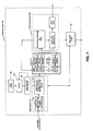
- FIG. 7 shows a system block diagram of a pulse-input ASIC, according to an embodiment of the invention.
- Pulse-input ASIC 700 can correspond, for example, to the pulse-input ASIC 137 shown in FIGS. 1 and 4 .
- pulse-input ASIC 700 includes edge detector 710, memory 720, pulse-input engine 730, zero-speed tester 740, count accumulator 750, counter 755 and clock 760.
- pulse-input ASIC 700 is shown as an ASIC, other embodiments are possible where this component is analog and/or digital circuitry.
- Edge detector 710 includes input pulse trigger circuit 715 and capture engine 717.
- Capture engine 717 is coupled to count accumulator 750, which in turn is coupled to counter 755.
- Counter 755 is also coupled to clock 760.
- Capture engine 717 is also coupled to memory 720, which in turn is coupled to pulse-input engine 730.
- Zero speed tester 740 is coupled to both edge detector 710 and pulse-input engine 730.
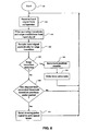
- FIG. 8 shows a flowchart of the operation of a capture engine of an edge detector, according to an embodiment of the invention.
- the process begins.
- input-pulse trigger circuit with adaptive debounce filter 715 receives the input signal from comparator network 600.
- the adaptive debounce filter of input-pulse trigger circuit 715 filters out noise transients and edge oscillations associated with the received pulse-input signal.
- Input-pulse trigger circuit 715 includes an adaptive debounce filter that filters out noise transients and edge oscillations associated with the received pulse-input signal.
- the adaptive debounce filter can be, for example, implemented in hardware or software within the input-pulse trigger circuit 715.
- the adaptive debounce filters can be implemented in software (e.g., using VHSIC Hardware Description Language (VHDL) software), which is then complied into hardware within, for example, an ASIC.
- VHDL VHSIC Hardware Description Language
- the adaptive debounce filter can have an associated adaptive debounce filter length, for example, of eight times the period of the previous pulse of the input signal.
- an input signal can accelerate at most by a factor of eight from the previous input signal.
- the period of an input signal can increase at most by a factor of eight from the period of the input signal for a previous pulse.
- the initial adaptive debounce filter length can be set to, for example, to 12.6 ⁇ sec if the measurement system is just starting up, if a missing pulse is detected (as described below in reference to step 870) or if the detected speed of the gear drops below a detectable minimum (e.g., below 0.5 Hz).
- the specific adaptive debounce filter length can subsequently change as the operation of the input-pulse trigger circuit 715 continues.
- FIG. 9 shows an example of an input signal and a filtered signal based on an adaptive debounce filter, according to an embodiment of the invention.
- input signal 900 can typically include spurious edge transitions such as a noise transient 910 and an edge oscillation 920.
- Filtered signal 950 shows the input signal 900 after it has filtered by the adaptive debounce filter. Note that the filtered signal 950 is shifted in time from the input signal 900 by an amount corresponding to the filter delay 980.
- the noise transient 910 and the edge oscillation 920 of the input signal have been removed from the filtered signal 950. Consequently, such undesirable transients are less likely to be mistakenly identified as pulses associated with the gear teeth. Accordingly, the calculated time values are more likely to be accurately associated with pulses associated with the gear teeth.
- capture engine 717 receives the filtered input signal from input-pulse trigger circuit 715 and periodically samples the input signal for edge transitions. Capture engine 717 can sample either the raising edge transitions or the trailing edge transitions from the input signal. At conditional step 830, capture engine 717 determines whether an edge transition was detected. If an edge transition was detected, the process proceeds to step 840. At step 840, a position counter within the capture engine 717 is incremented. At step 850, the time value associated with the detected edge transition from the input signal is provided to memory 720. The time value can be, for example, a 24-bit time value based on a counter signal received at the capture engine 717 by the count accumulator 750.
- the time value can be stored in memory 720 having, for example, in a circular array memory structure.
- the circular array can be, for example, an Ng by 24-bit array, where Ng equals the maximum number of gear teeth allowed on the gear being measured.
- the circular array can therefore store pulses associated with one or more revolutions.
- gear 10 has 256 teeth; N g is 256; and 256 time values are stored by memory 720 in a circular manner. Once 256 time values, corresponding to one complete revolution pattern of the gear, have been stored in memory 720, new time values can be stored over the previously stored time values in a circular manner.
- the time values stored by memory 720 are provided to pulse-input engine 730.
- the gear has 60 teeth; the circular array can store four revolutions of the gear for a total of 240 pulses within the 256 fields within the array memory structure.
- conditional step 860 capture engine 717 determines whether the elapsed time from the last detected edge transition exceeds a threshold. If the elapsed time from the last detected edge transition does not exceed the threshold, the process proceeds to step 810.
- the threshold can be, for example, based on the frequency of the input signal. For example, the threshold can be one fourth of the frequency of the input signal, or the four times the previous time period between pulses. If no new pulse is detected within an elapsed time period that exceeds the threshold, then it is assumed that a pulse is missing.
- a missing-pulse signal is sent to the zero-speed tester 740.
- the zero-speed tester 740 can then perform an input test whereby a test-pulse signal is generated and verified through the comparator network 134.
- the switches shown in FIG. 4 can be used to send a pulse from the zero-speed test 740 to perform the input test.
- the missing-pulse signal when a missing pulse is detected, is provided to an indicator, which quickly indicates to the user than a missing pulse has been detected.
- the missing-pulse indication can be terminated once a valid input signal is detected.
- the input signal is set zero, however, after a timeout period has elapsed with detecting a valid input signal. The timeout period allows the user to wait for a period of time before shutting down the equipment associated with the gear being measured (e.g., a power plant associated with a turbine gear being measured).
- the missing-pulse signal when missing pulses are intermittently detected, can be used to diagnose whether the input signal has a problem or is noisy.
- the missing-pulse indication can be toggled to indicate that the measurement system has a noise or sensor problem.
- pulse-input engine 730 receives the time values stored in memory 720. Pulse-input engine 730 calculates the pulse-to-pulse delays based on these received time values. In other words, pulse-input engine 730 receives time values indicative of detected edge transitions in the received input signal, and then calculates variations the times between adjacent edge transitions.
- the pulse-input engine 730 calculates the pulse-to-pulse delays differently based on a predefined threshold, which relates to speed of the gear rotation and the number of gear teeth.
- a predefined threshold which relates to speed of the gear rotation and the number of gear teeth.
- the pulse-to-pulse delay can be measured on a per pulse basis so that a new value is calculated for every gear tooth.
- the pulse-to-pulse delay can be averaged over multiple pulses so that a new value is calculated over multiple gear teeth. The faster the gear rotating, the more gear teeth will rotate past sensor 110 for a given time period.
- Calculating the pulse-to-pulse delays differently based on a predefined threshold provides the additional benefit of optimizing the measurement accuracy when the gear is rotating relatively slowly or relatively quickly while also providing a relatively quick measurement response time.
- measurement accuracy should be greater for higher gear rotation rates. For example, for gear rotation rates from 2,000 RPM to 32,000 RPM, accuracy with less than a 0.01% error is desirable while, for gear rotation rates from 0.5 RPM to 2,000 RPM, accuracy with less than a 0.1% error is acceptable to achieve quick measurement response.
- the desired accuracies are maintained while providing a relatively quick measurement response such as, for example, in the 100 msec range. In critical control applications, such as those for a high power turbine, this relatively quick measurement response advantageously detects problems quickly so that the measured system can be controlled quickly.
- the pulse-input ASIC 700 samples the input signal at a given sampling rate (e.g., 4 MHz).
- a sampling rate e.g. 4 MHz.
- sampling as many gear teeth as possible can minimize the errors caused by the data sampling.
- the measurement response time should not exceed a desired time.
- the gears being measured inherently have imperfections in their shape and construction, which results in an amount of time jitter for every measurement. This in turn results in measurement errors because time jitter directly relates into RPM measurement errors. Consequently, calculating the pulse-to-pulse delays over multiple pulses (i.e., over multiples of the number of gear teeth), when a predefined threshold is exceeded, reduces the jitter from the measurement because edge detection can be triggered on the same event for each measurement. At the same time, calculating the pulse-to-pulse delays on a per-pulse basis (i.e., over a single gear tooth) when a predefined threshold is not exceeded allows the system to measure slowly rotating gears. Thus, accuracy of the speed measurement is optimized for both cases.
- certain types of systems to be measured operate with changing angular velocity.
- a diesel engine having four cylinders and a flywheel produces an accelerate-decelerate type of pattern having an average RPM.
- measuring around the entire gear or multiples of the entire gear allows an accurate RPM measurement within a desired measurement response time.
- accuracy of the speed measurement is optimized both when a predefined threshold is exceeded and when the predefined threshold is not exceeded.
- Calculating the pulse-to-pulse delays differently based on a predefined threshold can be implemented using hysteresis. This allows minimizes any unnecessary oscillation between measuring on a per-pulse basis and measuring over multiple pulses.
- FIG. 10 shows a flow chart of the operation of the main processors, according to an embodiment of the invention.
- the process begins.
- the pulse-to-pulse delay values are received at each of the main processors 140, 150 and 160.
- the pulse-input modules 135 A, B and C provide pulse-to-pulse delay values to main processors 140, 150 and 160, respectively.
- each of the main processors 140, 150 and 160 calculates a pulse rate based on the pulse-to-pulse delay values received at that main processor.
- the pulse rate corresponds to the RPM of the gear 10 (shown in FIG. 2 ).
- One possible indication that an independent channel within the pulse-input module is not functional is, for example, that the corresponding main processor 140, 150 or 160 exceeds a threshold of accuracy in relationship to the voted value for a predefined time period.
- step 1040 the median value is selected. For example, if the main processor 150 received the lowest value, main processor 140 received the middle value and main processor 160 received the highest value, then the value from main processor 140 is selected. The remaining values for main processors 150 and 160 are discarded for this analysis time.
- the highest pulse rate corresponding to the highest RPM value measured for the gear
- step 1070 the value for the functional independent channel within the pulse-input module and the corresponding main processor 140, 150 or 160 is selected. This non-zero value is selected as the RPM value and the two zero values are discarded.
- process described in reference to FIG. 10 involved three a triple redundant system (e.g., having three independent input channels within the pulse-input module each being uniquely associated with one of three main processors), process can be applied to other configurations.
- the voting among the four main processors can be similar.
- an average of the middle two values can be used.
- the process described in reference to FIG. 10 can be used.
Landscapes
- Physics & Mathematics (AREA)
- General Physics & Mathematics (AREA)
- Transmission And Conversion Of Sensor Element Output (AREA)
- Combined Controls Of Internal Combustion Engines (AREA)
- Measuring Frequencies, Analyzing Spectra (AREA)
Claims (18)
- Vorrichtung zum Ermitteln einer Umdrehungsgeschwindigkeit für ein Zahnrad, umfassend:einen Flankendetektor (710), wobei der Flankendetektor (710) so ausgebildet ist, dass er ein Eingangssignal von einem Sensor (110) und ein Zählersignal empfängt, wobei das Eingangssignal einem Signal in Verbindung mit einem sich drehenden Zahnrad (10) entspricht, welches eine Mehrzahl von Verzahnungen aufweist, wobei jede Verzahnung aus der Mehrzahl von Verzahnungen einem Flankenübergang vom Eingangssignal entspricht, wobei der Flankendetektor weiter so ausgebildet ist, dass er eine Mehrzahl von Zeitwerten auf der Grundlage des Eingangssignals und des Zöhlersignals sendet, wobei jeder Zeitwert aus der Mehrzahl der Zeitwerte in eindeutig definierter Weise mit einem ermittelten Flankenübergang vom Eingangssignal in Verbindung steht;einen Speicher (720), der mit dem Flankendetektor gekoppelt ist, wobei der Speicher so ausgebildet ist, dass er vom Flankendelektor die Mehrzahl der Zeitwerte empfängt, wobei der Speicher so ausgebildet ist, dass er die Mehrzahl der Zeitwerte speichert:einen Impulseingangsmotor (730), der mit dem Speicher (720) gekoppelt ist, wobei der Impulseingangsmotor (730) so ausgebildet ist, dass er eine Mehrzahl von Puls-zu-Puls-Verzögerungen auf der Grundlage der Mehrzahl der Zeitwerte, die im Speicher (720) gespeichert sind, berechnet, undeinen Hauptprozessor (150, 160, 170), der so ausgebildet ist, dass er die Umdrehungsgeschwindigkeit für das Zahnrad durch Berechnen einer Impulsrate auf der Grundlage der Puls-zu-Puls-Verzögerungen ermittelt,gekennzeichnet durchein Impulseingangsmodul (130), umfassend den Flankendetektor (710), den Speicher (720) und den Impulseingangsmotor (730), undeine Eingangseinrichtung (180), die mit dem Impulseingangsmodul (130) gekoppelt ist, wobei die Eingangseinrichtung (180) so ausgebildet ist, dass sie von einem Benutzer empfangene Sensorinformation an das Impulseingangsmodul (130) liefert, wobei die Sensorinformation eine oder mehrere der folgenden umfasst: eine Anzeige vom Sensortyp, eine Verzahnungszahlanzeige, eine Anzeige vom Flankentyp und eine Aktivsensor-Feldspannungsanzeige.
- Vorrichtung nach Anspruch 1, weiter umfassend einen Satz von Houptprozessoren (150, 160, 170], die so ausgebildet sind, dass sie die Umdrehungsgeschwindigkeit für das Zahnrad durch Berechnen einer Impulsrate auf der Grundlage der Puls-zu-Puls-Verzögerungen ermitteln.
- Vorrichtung nach Anspruch 2, wobei das Impulseingangsmodul (130) einen Satz von Impulseingangszweigen (132) aufweist.
- Vorrichtung nach Anspruch 3, wobei jeder Impulseingangszweig (132) ein Filternetzwerk (133) und ein Komparatornetzwerk (134) aufweist.
- Vorrichtung nach einem der vorhergehenden Ansprüche, wobei:der Flankendetektor weiter einen Eingangsfilter aufweist, der Eingangsfilter einen Gültige-Daten-Zähler und einen Schweilwertselektor aufweist, der Eingangsfilter so ausgebildet ist, dass er eine gültige Anzeige vorsieht, wenn der Gültige-Daten-Zähler einen vorbestimmten Schwellwert überschreitet, der Schweilwertselektor des Eingangsfilters so ausgebildet ist, dass er den vorbestimmten Schwellwert auf der Grundlage einer Eingangsfrequenz in Zusammenhang mit dem Eingangssignal auswählt.
- Vorrichtung nach einem der vorhergehenden Ansprüche, weiter umfassend:einen Nullgeschwindigkeitstester (740), der mit dem Flankendetektor und dem Impulseingangsmotor (730) gekoppelt ist, wobei der Nullgeschwindigkeitstester (740) so ausgebildet ist, dass er ein Testsignal vom Flankendetektor empfängt und ein Testimpulssignal an einen Komparator sendet, der mit dem Flankendetektor gekoppelt ist,wobei der Flankendetektor so ausgebildet ist, dass er das Testsignal zum Nullgeschwindigkeitstester sendet, wenn der Flankendetektor eine Frequenz des Eingangssignals unter einem vorbestimmten Schwellwert misst.
- Vorrichtung nach einem der vorhergehenden Ansprüche, wobei das Impulseingangsmodul (130) so ausgebildet ist, dass es ein Zeitintervall zwischen Impulsen vom Eingangssignal auf einer Einzelimpulsbasis prüft, das Impulseingangsmodul (130) so ausgebildet ist, dass es eine Impulsausfallsanzeige sendet, wenn die Intervallzeit einen vorbestimmten Schwellwert überschreitet, wobei der vorbestimmte Schwellwert auf eine Frequenz des Eingangssignals bezogen ist.
- Vorrichtung nach einem der vorhergehenden Ansprüche , wobei der Flankendetektor (710) weiter aufweist:einen adaptiven Entprellungsfilter mit einer zugehörigen Entprellungsfilterlänge, die größer als eine Länge eines unechte Flankenübergangs ist, wobei der adaptive Entprellungsfilter so ausgebildet ist, dass er die zugehörige Entprellungsfilterlänge auf der Grundlage einer Frequenz des Eingangssignals einstellt.
- Vorrichtung nach einem der vorhergehenden Ansprüche, wobei:der Speicher (720) einen Eingangsanschluss und einen Ausgangsanschluss aufweist, wobei der Eingangsanschluss des Speichers an den Flankendetektor gekoppelt ist, wobei der Ausgangsanschluss des Speichers an den Impulseingangsmotor (730) gekoppelt ist, wobei der Speicher (720) so ausgebildet ist, dass der Zeitwert für jeden ermittelten Flankenübergang ringförmig gespeichert wird.
- Vorrichtung nach einem der vorhergehenden Ansprüche, wobei das Eingangssignal eine Mehrzahl von Impulsen mit einer Frequenz zwischen im Wesentlichen 0,5 Hz und 32.000 Hz hat.
- Vorrichtung nach einem der Ansprüche 2 bis 10, weiter umfassend:einen zweiten Flankendetektor, wobei der zweite Flankendetektor so ausgebildet ist, dass er das Signal und das Taktzeitgebersignal empfängt,wobei der zweite Flankendetektor weiter so ausgebildet ist, dass er seinen eigenen Zeitwert für jeden ermittelten Flankenübergang vom Eingangssignal sendet;einen zweiten Speicher, der mit dem zweiten Flankendetektor gekoppelt ist, wobei der zweite Speicher so ausgebildet ist, dass er vom zweiten Flankendetektor seinen eigenen Zeitwert für jeden ermittelten Flankenübergang vom Eingangssignal empfängt, wobei der zweite Speicher so ausgebildet ist, dass er den Zeitwert für jeden ermittelten Flankenübergang für den zweiten Flankendetektor speichert;einen zweiten Impulseingangsmotor, der mit dem zweiten Speicher gekoppelt ist, wobei der zweite Impulseingangsmotor so ausgebildet ist, dass er eine Puls-zu-Puls-Verzögerung auf der Grundlage des Zeitwerts für jeden ermittelten Flankenübergang berechnet, der im zweiten Speicher gespeichert ist;einen dritten Flankendetektor, wobei der dritte Flankendetektor so ausgebildet ist, dass er das Signal und das Taktzeitgebersignal empfängt,wobei der dritte Flankendetektor weiter so ausgebildet ist, dass er seinen eigenen Zeitwert für jeden ermittelten Hankenübergang vom Eingangssignal sendet;einen dritten Speicher, der mit dem dritten Flankendetektor gekoppelt ist,wobei der dritte Speicher so ausgebildet ist, dass er vom dritten Flankendetektor seinen eigenen Zeitwert für jeden ermittelten Flankenübergang vom Eingangssignal empfängt, wobei der dritte Speicher so ausgebildet ist, dass er den Zeitwert für jeden ermittelten Flankenübergang für den dritten Flankendetektor speichert; undeinen dritten Impulseingangsmotor, der mit dem dritten Speicher gekoppelt ist, wobei der dritte Impulseingangsmotor so ausgebildet ist,dass er eine Puls-zu-Puls-Verzögerung auf der Grundlage des Zeitwerts für jeden ermittelten Flankenübergang berechnet, der im dritten Speicher gespeichert ist.
- Vorrichtung nach Anspruch 11, umfassend:mindestens drei Impulseingangsmotoren,einen ersten Prozessor (150), der mit dem ersten Im pulseingangsmotor gekoppelt ist, wobei der erste Prozessor (150) eine Impulsrate auf der Grundlage der Puls-zu-Puls-Verzögerung vom ersten Impulseingangsmotor berechnet;einen zweiten Prozessor (160), der mit dem zweiten Impulseingangsmotor und dem ersten Prozessor (150) gekoppelt ist, wobei der zweite Prozessor (160) eine Impulsrate auf der Grundlage der Puls-zu-Puls-Verzögerung vom zweiten Impulseingangsmotor berechnet; undeinen dritten Prozessor (170), der mit dem dritten Impulseingangsmotor, dem ersten Prozessor (150) und dem zweiten Prozessor (160) gekoppelt ist, wobei der dritte Prozessor (170) eine Impulsrate auf der Grundlage der Puls-zu-Puls-Verzögerung vom dritten Impulseingangsmotor berechnet,wobei der erste Prozessor (150), der zweite Prozessor (160) und der dritte Prozessor (170) eine abgestimmte Impulsrate auf der Grundlage der vom ersten Prozessor (150) berechneten Impulsrate, der vom zweiten Prozessor (160) berechneten Impulsrate und der vom dritten Prozessor (170) berechneten Impulsrate berechnet.
- Verfahren zum Ermitteln einer Umdrehungsgeschwindigkeit für ein Zahnrad mit einer Mehrzahl von Verzahnungen, enthaltend eine erste Verzahnung und eine zweite Verzahnung, die sich von der ersten Verzahnung unterscheidet, umfassend:Ermitteln einer Mehrzahl von Flankenübergängen in einem Eingangssignal wobei die Mehrzahl der Flankenübergänge einen ersten Flankenübergang und einen zweiten Flankenübergang aufweisen, wobei der erste Flankenübergang mit der ersten Verzahnung in Verbindung steht, wobei der zweite Flankenübergang mit der zweiten Verzahnung in Verbindung steht;Speichern eines Zeitwerts für jeden Flankenübergang von der Mehrzahl von Flankenübergängen;Empfangen der Sensorinformation, umfassend eine oder mehrere der folgenden: eine Anzeige vom Sensor-Typ, eine Verzahnungszahlanzeige, eine Anzeige vom Flankentyp und eine Aktivsensor-Feldspannungsanzeige von einem Benutzer mittels einer Eingabeeinrichtung (180):Berechnen einer Mehrzahl von Puls-zu-Puls-Verzögerungen auf der Grundlage des Zeitwerts für jeden Flankenübergang von der Mehrzahl der Flankenübergänge, wobei die Berechnung der Mehrzahl von Puls-zu-Puls-Verzögerungen auf der Grundlage der empfangenen Sensorinformation erfolgt; undErmitteln der Umdrehungsgeschwindigkeit für das Zahnrad durch Berechnen einer Impulsrate auf der Grundlage der Puls-zu-Puls-Verzögerungen.
- Verfahren nach Anspruch 13, wobei der Ermittlungsschritt, der Speicherschritt und der Berechnungsschritt getrennt für jedes der mindestens drei Untersysteme berechnet werden, die parallel betrieben werden.
- Verfahren nach Anspruch 14, wobei jedes Untersystem weiter ausführt:Messen einer Intervallzeit zwischen einem ersten Flankenübergang und einem zweiten Flankenübergang von der Mehrzahl der Flankenübergänge; undSenden einer Impulsausfallsanzeige, wenn die Intervallzeit einen vorbestimmten Schwellwert überschreitet.
- Verfahren nach Anspruch 14 oder 15, wobei jedes Untersystem weiter ausführt:Ermitteln eines Testsignals mit einer Frequenz unter einer vorbestimmten Frequenz;Senden eines Nullgeschwindigkeitstestimpulses an einen Vorschaltkomparator, wenn das Testsignal ermittelt wird; undAussetzen des Speicherschritts für den Nullgeschwindigkeitstestimpuls, wenn das Testsignal ermittelt wird.
- Verfahren nach einem der Ansprüche 14 bis 16, wobei jedes Untersystem weiter ausführt;Messen einer Intervallzeit zwischen einem ersten Flankenübergang und einem zweiten Flankenübergang von der Mehrzahl der Flankenübergänge; undFiltern des ersten Flankenübergangs, wenn die Intervallzeit unter einem vorbestimmten Schwellwert liegt, wobei der vorbestimmte Schwellwert auf der Grundlage einer Frequenz des Eingangssignals erfolgt.
- Verfahren noch einem der Ansprüche 14 bis 17, weiter umfassend:Empfangen einer Feldspannungsanzeige, wenn die Anzeige vom SensorTyp einen aktiven Sensor anzeigt.
Applications Claiming Priority (3)
| Application Number | Priority Date | Filing Date | Title |
|---|---|---|---|
| US10/136,334 US6711513B2 (en) | 2002-05-02 | 2002-05-02 | Fault tolerant apparatus and method for determining a revolution rate of a gear |
| US136334 | 2002-05-02 | ||
| PCT/US2003/013579 WO2003094408A2 (en) | 2002-05-02 | 2003-05-01 | Fault tolerant apparatus and method for determining a revolution rate of a gear |
Publications (3)
| Publication Number | Publication Date |
|---|---|
| EP1500026A2 EP1500026A2 (de) | 2005-01-26 |
| EP1500026A4 EP1500026A4 (de) | 2010-12-22 |
| EP1500026B1 true EP1500026B1 (de) | 2014-11-05 |
Family
ID=29268928
Family Applications (1)
| Application Number | Title | Priority Date | Filing Date |
|---|---|---|---|
| EP03733919.9A Expired - Lifetime EP1500026B1 (de) | 2002-05-02 | 2003-05-01 | Fehlertolerante vorrichtung und verfahren zur bestimmung einer umdrehungsgeschwindigkeit eines zahnrads |
Country Status (6)
| Country | Link |
|---|---|
| US (2) | US6711513B2 (de) |
| EP (1) | EP1500026B1 (de) |
| AU (1) | AU2003239335A1 (de) |
| DK (1) | DK1500026T3 (de) |
| ES (1) | ES2525874T3 (de) |
| WO (1) | WO2003094408A2 (de) |
Families Citing this family (10)
| Publication number | Priority date | Publication date | Assignee | Title |
|---|---|---|---|---|
| US6850807B2 (en) * | 2001-09-10 | 2005-02-01 | Kabushiki Kaisha Toshiba | Triple redundant control device and method |
| DE102010029847A1 (de) * | 2009-07-30 | 2011-02-03 | Continental Teves Ag & Co. Ohg | Elektronische Sensorsignalauswerteschaltung in Kraftfahrzeugen |
| US9052330B2 (en) | 2010-08-16 | 2015-06-09 | Invensys Systems, Inc. | Enhanced rotation measurement |
| DE102011078586A1 (de) * | 2011-07-04 | 2013-01-10 | Robert Bosch Gmbh | Redundante Bestimmung der Drehbewegung einer Elektromaschine |
| US10746795B2 (en) | 2012-10-30 | 2020-08-18 | Nxp Usa, Inc. | Method and apparatus for at-speed scan shift frequency test optimization |
| DE102013217824A1 (de) * | 2013-09-06 | 2015-03-12 | Robert Bosch Gmbh | Vorrichtung und Verfahren zum Ermitteln einer geeigneten Position einer Sensoreinrichtung |
| EP3249411A1 (de) * | 2016-05-27 | 2017-11-29 | Schneider Electric Industries SAS | Verfahren und vorrichtung zur ermittlung der drehzahl eines motors |
| FR3067889B1 (fr) * | 2017-06-14 | 2019-06-28 | Safran Aircraft Engines | Procede de mesure de vitesse de rotation d'un arbre de turbomachine tenant compte du bruit de mesure |
| US11387941B2 (en) * | 2020-02-04 | 2022-07-12 | Macronix International Co., Ltd | Signal transceiving system and method |
| DE102022102452A1 (de) * | 2022-02-02 | 2023-08-03 | Knorr-Bremse Systeme für Nutzfahrzeuge GmbH | Auswerteschaltung und Verfahren zum Überwachen und Auslesen eines passiven Drehzahlsensors |
Citations (3)
| Publication number | Priority date | Publication date | Assignee | Title |
|---|---|---|---|---|
| US4055993A (en) * | 1976-05-07 | 1977-11-01 | United Technologies Corporation | Sub-cyclic measurement of speed of an internal combustion engine |
| US5928340A (en) * | 1997-09-08 | 1999-07-27 | Ford Motor Company | Apparatus for translating a bias signal into one of two different bias signals for a switching device |
| DE10151679A1 (de) * | 2000-12-23 | 2002-07-04 | Bosch Gmbh Robert | Verfahren zur Anpassung einer Signalauswertung |
Family Cites Families (16)
| Publication number | Priority date | Publication date | Assignee | Title |
|---|---|---|---|---|
| US3870947A (en) | 1973-11-12 | 1975-03-11 | Leslie L Fields | Method and apparatus for measuring the dwell and rpm of an engine |
| US4081995A (en) * | 1977-02-22 | 1978-04-04 | Rockwell International Corporation | Apparatus and method for extrapolating the angular position of a rotating body |
| JPS5439732A (en) * | 1977-09-05 | 1979-03-27 | Toyota Motor Corp | Ignition timing control for internal combustion engine |
| DE3005658A1 (de) | 1980-02-15 | 1981-10-01 | Klöckner-Humboldt-Deutz AG, 5000 Köln | Verfahren und anlage zum regeln der differenzdrehzahl zweier mit unterschiedlicher drehzahl rotierender bauteile, insbesondere von zentrifugentrommel und foerderschnecke einer schneckenzentrifuge |
| US4547683A (en) | 1982-10-18 | 1985-10-15 | Intersil, Inc. | High speed charge balancing comparator |
| US4841276A (en) * | 1985-06-17 | 1989-06-20 | Roy P. Abel | Vehicle low speed warning system |
| JPH0244258A (ja) * | 1988-08-05 | 1990-02-14 | Akebono Brake Ind Co Ltd | 回転体の回転速度演算装置 |
| JPH0291433A (ja) * | 1988-09-27 | 1990-03-30 | Fuji Heavy Ind Ltd | エンジンのクランク角タイミング検出装置 |
| GB2270177B (en) * | 1992-08-31 | 1995-11-22 | Silicon Systems Inc | Programmable system for the synchronization of an electronic angular position indicator |
| US5287070A (en) | 1992-09-02 | 1994-02-15 | Ncr Corporation | Balanced voltage comparator |
| US5537583A (en) | 1994-10-11 | 1996-07-16 | The Boeing Company | Method and apparatus for a fault tolerant clock with dynamic reconfiguration |
| US5613064A (en) | 1995-01-13 | 1997-03-18 | Curtin; Keith W. | Output network for a fault tolerant control system |
| US5596153A (en) | 1995-05-02 | 1997-01-21 | New Holland North America, Inc. | Measurement of rotational velocity and torque |
| US6141769A (en) | 1996-05-16 | 2000-10-31 | Resilience Corporation | Triple modular redundant computer system and associated method |
| US6535811B1 (en) * | 1999-11-03 | 2003-03-18 | Holley Performance Products, Inc. | System and method for real-time electronic engine control |
| JP3715868B2 (ja) * | 2000-06-15 | 2005-11-16 | 三菱電機株式会社 | 内燃機関のノック制御装置 |
-
2002
- 2002-05-02 US US10/136,334 patent/US6711513B2/en not_active Expired - Lifetime
-
2003
- 2003-05-01 AU AU2003239335A patent/AU2003239335A1/en not_active Abandoned
- 2003-05-01 DK DK03733919.9T patent/DK1500026T3/en active
- 2003-05-01 EP EP03733919.9A patent/EP1500026B1/de not_active Expired - Lifetime
- 2003-05-01 WO PCT/US2003/013579 patent/WO2003094408A2/en not_active Ceased
- 2003-05-01 ES ES03733919.9T patent/ES2525874T3/es not_active Expired - Lifetime
-
2004
- 2004-02-03 US US10/769,877 patent/US6823275B2/en not_active Expired - Lifetime
Patent Citations (3)
| Publication number | Priority date | Publication date | Assignee | Title |
|---|---|---|---|---|
| US4055993A (en) * | 1976-05-07 | 1977-11-01 | United Technologies Corporation | Sub-cyclic measurement of speed of an internal combustion engine |
| US5928340A (en) * | 1997-09-08 | 1999-07-27 | Ford Motor Company | Apparatus for translating a bias signal into one of two different bias signals for a switching device |
| DE10151679A1 (de) * | 2000-12-23 | 2002-07-04 | Bosch Gmbh Robert | Verfahren zur Anpassung einer Signalauswertung |
Also Published As
| Publication number | Publication date |
|---|---|
| US20040158422A1 (en) | 2004-08-12 |
| US20030208329A1 (en) | 2003-11-06 |
| AU2003239335A8 (en) | 2003-11-17 |
| WO2003094408A3 (en) | 2004-05-13 |
| US6711513B2 (en) | 2004-03-23 |
| DK1500026T3 (en) | 2014-11-17 |
| EP1500026A4 (de) | 2010-12-22 |
| ES2525874T3 (es) | 2014-12-30 |
| US6823275B2 (en) | 2004-11-23 |
| WO2003094408A2 (en) | 2003-11-13 |
| EP1500026A2 (de) | 2005-01-26 |
| AU2003239335A1 (en) | 2003-11-17 |
Similar Documents
| Publication | Publication Date | Title |
|---|---|---|
| EP1500026B1 (de) | Fehlertolerante vorrichtung und verfahren zur bestimmung einer umdrehungsgeschwindigkeit eines zahnrads | |
| US6618688B2 (en) | Apparatus and method for determining absolute position with steering path and steering angle sensors | |
| CN102822484B (zh) | 用于分析处理内燃机的曲轴传感器和凸轮轴传感器的信号的电路装置和方法 | |
| US9784601B2 (en) | Apparatus and method for signal synchronization | |
| US5347277A (en) | Dual phase resolver to digital converter | |
| JP5341714B2 (ja) | 位相差式レゾルバ | |
| US6502025B1 (en) | Relative steering angle sensor diagnostic for momentary signal dropout | |
| JP5832751B2 (ja) | 自己診断可能な電子回路及び磁界検出装置 | |
| US5606252A (en) | Circuit for mooting broken or chipped teeth of encoder wheels via comparing temporal fluctuations between rising or falling edges and using edge with least fluctuation | |
| US20030117181A1 (en) | High accuracy method for determining the frequency of a pulse input signal over a wide frequency range | |
| US6910804B2 (en) | Resistive temperature device (RTD) module with improved noise immunity | |
| ES2270603T3 (es) | Metodo y sistema de deteccion de fallos por correccion sincronizada. | |
| KR20040070200A (ko) | 각속도센서 | |
| CN109596854B (zh) | 避免速度传感器在停车抖动时产生误脉冲的方法和结构 | |
| KR102665010B1 (ko) | 엔진 속도 측정 회로 | |
| US4761609A (en) | Tachometer signal conditioner | |
| US20070085726A1 (en) | Process for determining a time interval | |
| JP2016115357A (ja) | 位置測定装置の動作クロック信号を検査するための装置および方法 | |
| CN114441176B (zh) | 一种可变齿数转速基准检测方法及检测电路 | |
| CN101960261B (zh) | 用于确定旋转元件的转动位置的方法和设备 | |
| CN107709935B (zh) | 用于为同步电机鉴定故障的控制线路和方法 | |
| CN113405584A (zh) | 用于速度振动组合式传感器性能测试的测试方法及装置 | |
| JP2007163500A (ja) | 直交エンコーダを調整し、デコーダ処理速度を確立するシステム及び方法 | |
| RU2805375C1 (ru) | Способ определения исправной работы гиромоторов блока демпфирующих гироскопов | |
| JP2602096B2 (ja) | リニヤパルスモータ駆動制御装置 |
Legal Events
| Date | Code | Title | Description |
|---|---|---|---|
| PUAI | Public reference made under article 153(3) epc to a published international application that has entered the european phase |
Free format text: ORIGINAL CODE: 0009012 |
|
| 17P | Request for examination filed |
Effective date: 20041111 |
|
| AK | Designated contracting states |
Kind code of ref document: A2 Designated state(s): AT BE BG CH CY CZ DE DK EE ES FI FR GB GR HU IE IT LI LU MC NL PT RO SE SI SK TR |
|
| AX | Request for extension of the european patent |
Extension state: AL LT LV MK |
|
| DAX | Request for extension of the european patent (deleted) | ||
| A4 | Supplementary search report drawn up and despatched |
Effective date: 20101118 |
|
| 17Q | First examination report despatched |
Effective date: 20110331 |
|
| GRAP | Despatch of communication of intention to grant a patent |
Free format text: ORIGINAL CODE: EPIDOSNIGR1 |
|
| RIC1 | Information provided on ipc code assigned before grant |
Ipc: G06F 19/00 20110101AFI20140509BHEP Ipc: G01P 3/489 20060101ALI20140509BHEP |
|
| INTG | Intention to grant announced |
Effective date: 20140611 |
|
| GRAS | Grant fee paid |
Free format text: ORIGINAL CODE: EPIDOSNIGR3 |
|
| GRAA | (expected) grant |
Free format text: ORIGINAL CODE: 0009210 |
|
| AK | Designated contracting states |
Kind code of ref document: B1 Designated state(s): AT BE BG CH CY CZ DE DK EE ES FI FR GB GR HU IE IT LI LU MC NL PT RO SE SI SK TR |
|
| REG | Reference to a national code |
Ref country code: GB Ref legal event code: FG4D Ref country code: DE Ref legal event code: R081 Ref document number: 60346956 Country of ref document: DE Owner name: SCHNEIDER ELECTRIC SYSTEMS USA, INC., FOXBORO, US Free format text: FORMER OWNER: INVENSYS SYSTEMS, INC., IRVINE, CALIF., US |
|
| REG | Reference to a national code |
Ref country code: CH Ref legal event code: NV Representative=s name: E. BLUM AND CO. AG PATENT- UND MARKENANWAELTE , CH Ref country code: CH Ref legal event code: EP |
|
| REG | Reference to a national code |
Ref country code: AT Ref legal event code: REF Ref document number: 694948 Country of ref document: AT Kind code of ref document: T Effective date: 20141115 |
|
| REG | Reference to a national code |
Ref country code: DK Ref legal event code: T3 Effective date: 20141112 |
|
| REG | Reference to a national code |
Ref country code: IE Ref legal event code: FG4D |
|
| REG | Reference to a national code |
Ref country code: DE Ref legal event code: R096 Ref document number: 60346956 Country of ref document: DE Effective date: 20141211 |
|
| REG | Reference to a national code |
Ref country code: ES Ref legal event code: FG2A Ref document number: 2525874 Country of ref document: ES Kind code of ref document: T3 Effective date: 20141230 |
|
| REG | Reference to a national code |
Ref country code: NL Ref legal event code: T3 |
|
| REG | Reference to a national code |
Ref country code: AT Ref legal event code: MK05 Ref document number: 694948 Country of ref document: AT Kind code of ref document: T Effective date: 20141105 |
|
| PG25 | Lapsed in a contracting state [announced via postgrant information from national office to epo] |
Ref country code: FI Free format text: LAPSE BECAUSE OF FAILURE TO SUBMIT A TRANSLATION OF THE DESCRIPTION OR TO PAY THE FEE WITHIN THE PRESCRIBED TIME-LIMIT Effective date: 20141105 Ref country code: PT Free format text: LAPSE BECAUSE OF FAILURE TO SUBMIT A TRANSLATION OF THE DESCRIPTION OR TO PAY THE FEE WITHIN THE PRESCRIBED TIME-LIMIT Effective date: 20150305 |
|
| PG25 | Lapsed in a contracting state [announced via postgrant information from national office to epo] |
Ref country code: GR Free format text: LAPSE BECAUSE OF FAILURE TO SUBMIT A TRANSLATION OF THE DESCRIPTION OR TO PAY THE FEE WITHIN THE PRESCRIBED TIME-LIMIT Effective date: 20150206 Ref country code: SE Free format text: LAPSE BECAUSE OF FAILURE TO SUBMIT A TRANSLATION OF THE DESCRIPTION OR TO PAY THE FEE WITHIN THE PRESCRIBED TIME-LIMIT Effective date: 20141105 Ref country code: AT Free format text: LAPSE BECAUSE OF FAILURE TO SUBMIT A TRANSLATION OF THE DESCRIPTION OR TO PAY THE FEE WITHIN THE PRESCRIBED TIME-LIMIT Effective date: 20141105 Ref country code: CY Free format text: LAPSE BECAUSE OF FAILURE TO SUBMIT A TRANSLATION OF THE DESCRIPTION OR TO PAY THE FEE WITHIN THE PRESCRIBED TIME-LIMIT Effective date: 20141105 |
|
| PG25 | Lapsed in a contracting state [announced via postgrant information from national office to epo] |
Ref country code: CZ Free format text: LAPSE BECAUSE OF FAILURE TO SUBMIT A TRANSLATION OF THE DESCRIPTION OR TO PAY THE FEE WITHIN THE PRESCRIBED TIME-LIMIT Effective date: 20141105 Ref country code: SK Free format text: LAPSE BECAUSE OF FAILURE TO SUBMIT A TRANSLATION OF THE DESCRIPTION OR TO PAY THE FEE WITHIN THE PRESCRIBED TIME-LIMIT Effective date: 20141105 Ref country code: EE Free format text: LAPSE BECAUSE OF FAILURE TO SUBMIT A TRANSLATION OF THE DESCRIPTION OR TO PAY THE FEE WITHIN THE PRESCRIBED TIME-LIMIT Effective date: 20141105 Ref country code: RO Free format text: LAPSE BECAUSE OF FAILURE TO SUBMIT A TRANSLATION OF THE DESCRIPTION OR TO PAY THE FEE WITHIN THE PRESCRIBED TIME-LIMIT Effective date: 20141105 |
|
| REG | Reference to a national code |
Ref country code: DE Ref legal event code: R097 Ref document number: 60346956 Country of ref document: DE |
|
| PLBE | No opposition filed within time limit |
Free format text: ORIGINAL CODE: 0009261 |
|
| STAA | Information on the status of an ep patent application or granted ep patent |
Free format text: STATUS: NO OPPOSITION FILED WITHIN TIME LIMIT |
|
| 26N | No opposition filed |
Effective date: 20150806 |
|
| PG25 | Lapsed in a contracting state [announced via postgrant information from national office to epo] |
Ref country code: LU Free format text: LAPSE BECAUSE OF FAILURE TO SUBMIT A TRANSLATION OF THE DESCRIPTION OR TO PAY THE FEE WITHIN THE PRESCRIBED TIME-LIMIT Effective date: 20150501 Ref country code: IT Free format text: LAPSE BECAUSE OF NON-PAYMENT OF DUE FEES Effective date: 20150501 Ref country code: MC Free format text: LAPSE BECAUSE OF FAILURE TO SUBMIT A TRANSLATION OF THE DESCRIPTION OR TO PAY THE FEE WITHIN THE PRESCRIBED TIME-LIMIT Effective date: 20141105 |
|
| REG | Reference to a national code |
Ref country code: IE Ref legal event code: MM4A |
|
| PG25 | Lapsed in a contracting state [announced via postgrant information from national office to epo] |
Ref country code: SI Free format text: LAPSE BECAUSE OF FAILURE TO SUBMIT A TRANSLATION OF THE DESCRIPTION OR TO PAY THE FEE WITHIN THE PRESCRIBED TIME-LIMIT Effective date: 20141105 |
|
| REG | Reference to a national code |
Ref country code: FR Ref legal event code: PLFP Year of fee payment: 14 |
|
| PG25 | Lapsed in a contracting state [announced via postgrant information from national office to epo] |
Ref country code: IE Free format text: LAPSE BECAUSE OF NON-PAYMENT OF DUE FEES Effective date: 20150501 |
|
| REG | Reference to a national code |
Ref country code: DE Ref legal event code: R082 Ref document number: 60346956 Country of ref document: DE Representative=s name: FRIESE GOEDEN PATENTANWAELTE PARTGMBB, DE Ref country code: DE Ref legal event code: R082 Ref document number: 60346956 Country of ref document: DE Representative=s name: FRIESE GOEDEN, DE |
|
| REG | Reference to a national code |
Ref country code: FR Ref legal event code: PLFP Year of fee payment: 15 |
|
| PG25 | Lapsed in a contracting state [announced via postgrant information from national office to epo] |
Ref country code: HU Free format text: LAPSE BECAUSE OF FAILURE TO SUBMIT A TRANSLATION OF THE DESCRIPTION OR TO PAY THE FEE WITHIN THE PRESCRIBED TIME-LIMIT; INVALID AB INITIO Effective date: 20030501 Ref country code: BG Free format text: LAPSE BECAUSE OF FAILURE TO SUBMIT A TRANSLATION OF THE DESCRIPTION OR TO PAY THE FEE WITHIN THE PRESCRIBED TIME-LIMIT Effective date: 20141105 |
|
| PG25 | Lapsed in a contracting state [announced via postgrant information from national office to epo] |
Ref country code: TR Free format text: LAPSE BECAUSE OF FAILURE TO SUBMIT A TRANSLATION OF THE DESCRIPTION OR TO PAY THE FEE WITHIN THE PRESCRIBED TIME-LIMIT Effective date: 20141105 |
|
| REG | Reference to a national code |
Ref country code: FR Ref legal event code: PLFP Year of fee payment: 16 |
|
| REG | Reference to a national code |
Ref country code: DE Ref legal event code: R082 Ref document number: 60346956 Country of ref document: DE Representative=s name: FRIESE GOEDEN PATENTANWAELTE PARTGMBB, DE Ref country code: DE Ref legal event code: R081 Ref document number: 60346956 Country of ref document: DE Owner name: SCHNEIDER ELECTRIC SYSTEMS USA, INC., FOXBORO, US Free format text: FORMER OWNER: INVENSYS SYSTEMS, INC., IRVINE, CALIF., US |
|
| REG | Reference to a national code |
Ref country code: CH Ref legal event code: PFA Owner name: SCHNEIDER ELECTRIC SYSTEMS USA, INC., US Free format text: FORMER OWNER: INVENSYS SYSTEMS, INC., US |
|
| REG | Reference to a national code |
Ref country code: NL Ref legal event code: HC Owner name: SCHNEIDER ELECTRIC SYSTEMS USA, INC.; US Free format text: DETAILS ASSIGNMENT: CHANGE OF OWNER(S), CHANGE OF OWNER(S) NAME; FORMER OWNER NAME: INVENSYS SYSTEMS, INC. Effective date: 20180824 |
|
| REG | Reference to a national code |
Ref country code: DE Ref legal event code: R079 Ref document number: 60346956 Country of ref document: DE Free format text: PREVIOUS MAIN CLASS: G06F0019000000 Ipc: G16Z0099000000 |
|
| REG | Reference to a national code |
Ref country code: BE Ref legal event code: FP Effective date: 20150119 Ref country code: BE Ref legal event code: HC Owner name: SCHNEIDER ELECTRIC SYSTEMS USA, INC.; US Free format text: DETAILS ASSIGNMENT: CHANGE OF OWNER(S), CHANGEMENT DE NOM DU PROPRIETAIRE, CHANGEMENT DE NOM ET D'ADRESSE; FORMER OWNER NAME: INVENSYS SYSTEMS, INC. Effective date: 20181001 |
|
| REG | Reference to a national code |
Ref country code: ES Ref legal event code: PC2A Owner name: SCHNEIDER ELECTRIC SYSTEMS USA. INC. Effective date: 20190131 |
|
| PGFP | Annual fee paid to national office [announced via postgrant information from national office to epo] |
Ref country code: NL Payment date: 20220526 Year of fee payment: 20 |
|
| PGFP | Annual fee paid to national office [announced via postgrant information from national office to epo] |
Ref country code: GB Payment date: 20220524 Year of fee payment: 20 Ref country code: FR Payment date: 20220526 Year of fee payment: 20 Ref country code: ES Payment date: 20220614 Year of fee payment: 20 Ref country code: DK Payment date: 20220524 Year of fee payment: 20 Ref country code: DE Payment date: 20220527 Year of fee payment: 20 |
|
| PGFP | Annual fee paid to national office [announced via postgrant information from national office to epo] |
Ref country code: CH Payment date: 20220520 Year of fee payment: 20 Ref country code: BE Payment date: 20220526 Year of fee payment: 20 |
|
| REG | Reference to a national code |
Ref country code: DE Ref legal event code: R071 Ref document number: 60346956 Country of ref document: DE |
|
| REG | Reference to a national code |
Ref country code: NL Ref legal event code: MK Effective date: 20230430 |
|
| REG | Reference to a national code |
Ref country code: DK Ref legal event code: EUP Expiry date: 20230501 |
|
| REG | Reference to a national code |
Ref country code: CH Ref legal event code: PL |
|
| REG | Reference to a national code |
Ref country code: GB Ref legal event code: PE20 Expiry date: 20230430 |
|
| REG | Reference to a national code |
Ref country code: ES Ref legal event code: FD2A Effective date: 20230526 |
|
| PG25 | Lapsed in a contracting state [announced via postgrant information from national office to epo] |
Ref country code: ES Free format text: LAPSE BECAUSE OF EXPIRATION OF PROTECTION Effective date: 20230502 |
|
| PG25 | Lapsed in a contracting state [announced via postgrant information from national office to epo] |
Ref country code: GB Free format text: LAPSE BECAUSE OF EXPIRATION OF PROTECTION Effective date: 20230430 |