EP4135063B1 - Elektrodenverbindungsvorrichtung und -verfahren sowie kerbungsvorrichtung damit - Google Patents
Elektrodenverbindungsvorrichtung und -verfahren sowie kerbungsvorrichtung damit Download PDFInfo
- Publication number
- EP4135063B1 EP4135063B1 EP22736880.0A EP22736880A EP4135063B1 EP 4135063 B1 EP4135063 B1 EP 4135063B1 EP 22736880 A EP22736880 A EP 22736880A EP 4135063 B1 EP4135063 B1 EP 4135063B1
- Authority
- EP
- European Patent Office
- Prior art keywords
- sheet
- preceding sheet
- succeeding sheet
- electrode connecting
- arrangement
- Prior art date
- Legal status (The legal status is an assumption and is not a legal conclusion. Google has not performed a legal analysis and makes no representation as to the accuracy of the status listed.)
- Active
Links
Images


Classifications
-
- H—ELECTRICITY
- H01—ELECTRIC ELEMENTS
- H01M—PROCESSES OR MEANS, e.g. BATTERIES, FOR THE DIRECT CONVERSION OF CHEMICAL ENERGY INTO ELECTRICAL ENERGY
- H01M10/00—Secondary cells; Manufacture thereof
- H01M10/04—Construction or manufacture in general
- H01M10/0404—Machines for assembling batteries
-
- B—PERFORMING OPERATIONS; TRANSPORTING
- B26—HAND CUTTING TOOLS; CUTTING; SEVERING
- B26D—CUTTING; DETAILS COMMON TO MACHINES FOR PERFORATING, PUNCHING, CUTTING-OUT, STAMPING-OUT OR SEVERING
- B26D1/00—Cutting through work characterised by the nature or movement of the cutting member or particular materials not otherwise provided for; Apparatus or machines therefor; Cutting members therefor
- B26D1/01—Cutting through work characterised by the nature or movement of the cutting member or particular materials not otherwise provided for; Apparatus or machines therefor; Cutting members therefor involving a cutting member which does not travel with the work
- B26D1/04—Cutting through work characterised by the nature or movement of the cutting member or particular materials not otherwise provided for; Apparatus or machines therefor; Cutting members therefor involving a cutting member which does not travel with the work having a linearly-movable cutting member
- B26D1/06—Cutting through work characterised by the nature or movement of the cutting member or particular materials not otherwise provided for; Apparatus or machines therefor; Cutting members therefor involving a cutting member which does not travel with the work having a linearly-movable cutting member wherein the cutting member reciprocates
- B26D1/08—Cutting through work characterised by the nature or movement of the cutting member or particular materials not otherwise provided for; Apparatus or machines therefor; Cutting members therefor involving a cutting member which does not travel with the work having a linearly-movable cutting member wherein the cutting member reciprocates of the guillotine type
- B26D1/085—Cutting through work characterised by the nature or movement of the cutting member or particular materials not otherwise provided for; Apparatus or machines therefor; Cutting members therefor involving a cutting member which does not travel with the work having a linearly-movable cutting member wherein the cutting member reciprocates of the guillotine type for thin material, e.g. for sheets, strips or the like
-
- B—PERFORMING OPERATIONS; TRANSPORTING
- B26—HAND CUTTING TOOLS; CUTTING; SEVERING
- B26F—PERFORATING; PUNCHING; CUTTING-OUT; STAMPING-OUT; SEVERING BY MEANS OTHER THAN CUTTING
- B26F1/00—Perforating; Punching; Cutting-out; Stamping-out; Apparatus therefor
- B26F1/02—Perforating by punching, e.g. with relatively-reciprocating punch and bed
- B26F1/12—Perforating by punching, e.g. with relatively-reciprocating punch and bed to notch margins of work
-
- B—PERFORMING OPERATIONS; TRANSPORTING
- B65—CONVEYING; PACKING; STORING; HANDLING THIN OR FILAMENTARY MATERIAL
- B65H—HANDLING THIN OR FILAMENTARY MATERIAL, e.g. SHEETS, WEBS, CABLES
- B65H19/00—Changing the web roll
- B65H19/10—Changing the web roll in unwinding mechanisms or in connection with unwinding operations
- B65H19/18—Attaching, e.g. pasting, the replacement web to the expiring web
- B65H19/1842—Attaching, e.g. pasting, the replacement web to the expiring web standing splicing, i.e. the expiring web being stationary during splicing contact
- B65H19/1852—Attaching, e.g. pasting, the replacement web to the expiring web standing splicing, i.e. the expiring web being stationary during splicing contact taking place at a distance from the replacement roll
-
- H—ELECTRICITY
- H01—ELECTRIC ELEMENTS
- H01M—PROCESSES OR MEANS, e.g. BATTERIES, FOR THE DIRECT CONVERSION OF CHEMICAL ENERGY INTO ELECTRICAL ENERGY
- H01M10/00—Secondary cells; Manufacture thereof
- H01M10/04—Construction or manufacture in general
- H01M10/0486—Frames for plates or membranes
-
- H—ELECTRICITY
- H01—ELECTRIC ELEMENTS
- H01M—PROCESSES OR MEANS, e.g. BATTERIES, FOR THE DIRECT CONVERSION OF CHEMICAL ENERGY INTO ELECTRICAL ENERGY
- H01M4/00—Electrodes
- H01M4/02—Electrodes composed of, or comprising, active material
- H01M4/04—Processes of manufacture in general
- H01M4/0402—Methods of deposition of the material
- H01M4/0404—Methods of deposition of the material by coating on electrode collectors
-
- H—ELECTRICITY
- H01—ELECTRIC ELEMENTS
- H01M—PROCESSES OR MEANS, e.g. BATTERIES, FOR THE DIRECT CONVERSION OF CHEMICAL ENERGY INTO ELECTRICAL ENERGY
- H01M50/00—Constructional details or processes of manufacture of the non-active parts of electrochemical cells other than fuel cells, e.g. hybrid cells
- H01M50/50—Current conducting connections for cells or batteries
- H01M50/531—Electrode connections inside a battery casing
- H01M50/533—Electrode connections inside a battery casing characterised by the shape of the leads or tabs
-
- B—PERFORMING OPERATIONS; TRANSPORTING
- B65—CONVEYING; PACKING; STORING; HANDLING THIN OR FILAMENTARY MATERIAL
- B65H—HANDLING THIN OR FILAMENTARY MATERIAL, e.g. SHEETS, WEBS, CABLES
- B65H2301/00—Handling processes for sheets or webs
- B65H2301/40—Type of handling process
- B65H2301/46—Splicing
- B65H2301/461—Processing webs in splicing process
- B65H2301/4615—Processing webs in splicing process after splicing
- B65H2301/4617—Processing webs in splicing process after splicing cutting webs in splicing process
- B65H2301/46176—Processing webs in splicing process after splicing cutting webs in splicing process cutting both spliced webs simultaneously
-
- B—PERFORMING OPERATIONS; TRANSPORTING
- B65—CONVEYING; PACKING; STORING; HANDLING THIN OR FILAMENTARY MATERIAL
- B65H—HANDLING THIN OR FILAMENTARY MATERIAL, e.g. SHEETS, WEBS, CABLES
- B65H2301/00—Handling processes for sheets or webs
- B65H2301/40—Type of handling process
- B65H2301/46—Splicing
- B65H2301/462—Form of splice
- B65H2301/4622—Abutting article or web portions, i.e. edge to edge
-
- B—PERFORMING OPERATIONS; TRANSPORTING
- B65—CONVEYING; PACKING; STORING; HANDLING THIN OR FILAMENTARY MATERIAL
- B65H—HANDLING THIN OR FILAMENTARY MATERIAL, e.g. SHEETS, WEBS, CABLES
- B65H2301/00—Handling processes for sheets or webs
- B65H2301/40—Type of handling process
- B65H2301/46—Splicing
- B65H2301/463—Splicing splicing means, i.e. means by which a web end is bound to another web end
- B65H2301/4631—Adhesive tape
-
- B—PERFORMING OPERATIONS; TRANSPORTING
- B65—CONVEYING; PACKING; STORING; HANDLING THIN OR FILAMENTARY MATERIAL
- B65H—HANDLING THIN OR FILAMENTARY MATERIAL, e.g. SHEETS, WEBS, CABLES
- B65H2404/00—Parts for transporting or guiding the handled material
- B65H2404/70—Other elements in edge contact with handled material, e.g. registering, orientating, guiding devices
- B65H2404/73—Means for sliding the handled material on a surface, e.g. pushers
- B65H2404/732—Means for sliding the handled material on a surface, e.g. pushers in a direction perpendicular to a feeding / delivery direction
-
- B—PERFORMING OPERATIONS; TRANSPORTING
- B65—CONVEYING; PACKING; STORING; HANDLING THIN OR FILAMENTARY MATERIAL
- B65H—HANDLING THIN OR FILAMENTARY MATERIAL, e.g. SHEETS, WEBS, CABLES
- B65H2406/00—Means using fluid
- B65H2406/30—Suction means
- B65H2406/35—Other elements with suction surface, e.g. plate or wall
- B65H2406/351—Other elements with suction surface, e.g. plate or wall facing the surface of the handled material
-
- B—PERFORMING OPERATIONS; TRANSPORTING
- B65—CONVEYING; PACKING; STORING; HANDLING THIN OR FILAMENTARY MATERIAL
- B65H—HANDLING THIN OR FILAMENTARY MATERIAL, e.g. SHEETS, WEBS, CABLES
- B65H2801/00—Application field
- B65H2801/72—Fuel cell manufacture
-
- Y—GENERAL TAGGING OF NEW TECHNOLOGICAL DEVELOPMENTS; GENERAL TAGGING OF CROSS-SECTIONAL TECHNOLOGIES SPANNING OVER SEVERAL SECTIONS OF THE IPC; TECHNICAL SUBJECTS COVERED BY FORMER USPC CROSS-REFERENCE ART COLLECTIONS [XRACs] AND DIGESTS
- Y02—TECHNOLOGIES OR APPLICATIONS FOR MITIGATION OR ADAPTATION AGAINST CLIMATE CHANGE
- Y02E—REDUCTION OF GREENHOUSE GAS [GHG] EMISSIONS, RELATED TO ENERGY GENERATION, TRANSMISSION OR DISTRIBUTION
- Y02E60/00—Enabling technologies; Technologies with a potential or indirect contribution to GHG emissions mitigation
- Y02E60/10—Energy storage using batteries
-
- Y—GENERAL TAGGING OF NEW TECHNOLOGICAL DEVELOPMENTS; GENERAL TAGGING OF CROSS-SECTIONAL TECHNOLOGIES SPANNING OVER SEVERAL SECTIONS OF THE IPC; TECHNICAL SUBJECTS COVERED BY FORMER USPC CROSS-REFERENCE ART COLLECTIONS [XRACs] AND DIGESTS
- Y02—TECHNOLOGIES OR APPLICATIONS FOR MITIGATION OR ADAPTATION AGAINST CLIMATE CHANGE
- Y02P—CLIMATE CHANGE MITIGATION TECHNOLOGIES IN THE PRODUCTION OR PROCESSING OF GOODS
- Y02P70/00—Climate change mitigation technologies in the production process for final industrial or consumer products
- Y02P70/50—Manufacturing or production processes characterised by the final manufactured product
Definitions
- the present invention relates to an electrode connecting device capable of aligning and connecting two sheets (or films) in a longitudinal direction, an electrode connecting method, and a notching machine comprising same.
- secondary batteries refer to chargeable and dischargeable batteries unlike primary batteries that are not chargeable. Such a secondary battery is being widely used in phones, laptop computers, camcorders, electric vehicles, and the like.
- the secondary battery comprises an electrode assembly and a case that accommodates the electrode assembly, and the electrode assembly has a structure in which electrodes and separators are alternately stacked.
- the electrode tab is formed at each of the electrodes.
- the electrode tab is manufactured through a notching process, and the notching process comprises a winding roller, on which a band-shaped sheet is wound, a notching part, which notches an uncoated portion of the sheet supplied from the winding roller to manufacture an electrode tab, and a collecting roller, which collects the sheet in which the electrode tab is manufactured.
- the notching operation is performed after connecting an end portion of the sheet remaining in the used winding roller to an end portion of a sheet wound on the new winding roller.
- An object of the present invention for solving the above problems is to provide an electrode connecting device, an electrode connecting method, and a secondary battery notching machine comprising same, by which an used sheet and a new sheet can be aligned and connected to each other in a longitudinal direction. Accordingly, it is possible to prevent the generation of a stepped region between the used sheet and the new sheet, and as a result, it is possible to prevent the occurrence of a notching defect during a notching process.
- the present invention for solving the above problems provides an electrode connecting device for connecting an end of a preceding sheet to an end of a succeeding sheet, the electrode connecting device comprising: an arrangement member provided with an arrangement part on which the end of the preceding sheet is located adjacent to or overlapping with the end of the succeeding sheet; and a guide member comprising a guide bar which is provided movable between a support position to support a side portion of the preceding sheet and a side portion of the succeeding sheet during connecting of the end of the preceding sheet to the end of the succeeding sheet and a retreat position not to interfere with movements of the preceding sheet and the succeeding sheet.
- the arrangement member further may comprise a pathline which is provided at the support position and indicates the support position at which the guide bar is positioned.
- the electrode connecting device may further comprise a detection member which detects the side portion of the preceding sheet and the side portion of the succeeding sheet that are supported on the guide bar of the guide member, wherein the detection member comprises a first detection sensor, which is provided on one side of the guide bar and detects the side portion of the preceding sheet, and a second detection sensor, which is provided on the other side of the guide bar and detects the side portion of the succeeding sheet.
- the arrangement part may comprise one side-arrangement surface, on which the end of the preceding sheet is disposed, and the other side-arrangement surface, on which the end of the succeeding sheet is disposed, wherein the electrode connecting device comprises a cutting member, and when the end of the preceding sheet disposed on the one side-arrangement surface is disposed overlapping with the end of the succeeding sheet disposed on the other side-arrangement surface, the cutting member cuts overlapping portions of the preceding sheet and the succeeding sheet and correspondingly matches the end of the preceding sheet with the end of the succeeding sheet.
- a cutting groove, into which the cutting member is inserted, may be formed between the one side-arrangement surface and the other side-arrangement surface.
- the electrode connecting device may further comprise an adhesive member which connects the end of the preceding sheet disposed on the one side-arrangement surface to the end of the succeeding sheet disposed on the other side-arrangement surface.
- the adhesive member may comprise an adhesive tape which is attached to the end of the preceding sheet and the end of the succeeding sheet and connects and aligns the end of the preceding sheet to the end of the succeeding sheet.
- the electrode connecting device may further comprise a suction member provided with a first suction, which adheres the preceding sheet to the one side-arrangement surface through a suction force, and a second suction, which adheres the succeeding sheet to the other side-arrangement surface through a suction force.
- the pathline may have a rod shape and be separably coupled to a coupling groove formed in a surface of the arrangement member.
- the present invention provides an electrode connecting method for connecting an end of a preceding sheet to an end of a succeeding sheet, the electrode connecting method comprising: a process (a) of moving a guide member forward so that a guide bar of the guide member is moved from a retreat position of an arrangement member to a support position; a process (b) of correspondingly arranging the end of the preceding sheet and the end of the succeeding sheet on an arrangement part of the arrangement member, wherein the end of the preceding sheet and the end of the succeeding sheet are arranged adjacent to or overlapping with each other by supporting, on the guide bar, a side portion of the preceding sheet and a side portion of the succeeding sheet; and a process (c) of attaching an adhesive tape of an adhesive member to the end of the preceding sheet and the end of the succeeding sheet, which are arranged on the arrangement part of the arrangement member, so that the end of the preceding sheet is connected to the end of the succeeding sheet.
- a pathline may be provided at the support position to indicate the support position at which the guide bar is positioned.
- the process (b) may further comprise a detection process of detecting the side portion of the preceding sheet and the side portion of the succeeding sheet, which are supported on the guide bar, through a detection member that comprises a first detection sensor and a second detection sensor, wherein in the detection process, the side portion of the preceding sheet supported on the guide bar is detected by the first detection sensor, and the side portion of the succeeding sheet supported on the guide bar is detected by the second detection sensor.
- the process (b) may further comprise a process of, when the end of the preceding sheet and the end of the succeeding sheet arranged in the arrangement part are not matched, overlapping the end of the preceding sheet and the end of the succeeding sheet so that the non-matched portions are present in overlapping portions, wherein the electrode connecting method further comprises, between the process (b) and the process (c), a process (b1) of cutting the overlapping portions of the end of the preceding sheet and the end of the succeeding sheet by a cutting member and correspondingly matching the end of the preceding sheet with the end of the succeeding sheet.
- the process (b) may further comprise a process of adhering and fixing the end of the preceding sheet and the end of the succeeding sheet to the arrangement part by a suction member.
- a notching machine according to the present invention comprise the electrode connecting device.
- the electrode connecting device may align and connect the end of the preceding sheet to the end of the succeeding sheet. Accordingly, it is possible to prevent the generation of the stepped region between the end of the preceding sheet and the end of the succeeding sheet, and as a result, it is possible to prevent the occurrence of the defect during the sheet notching.
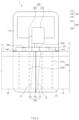
- An electrode connecting device 1 is to align and connect an end of a sheet that precedes (hereinafter, referred to as a preceding sheet) to an end of a sheet that succeeds (hereinafter, referred to as a succeeding sheet) in a longitudinal direction, thereby preventing the generation of a stepped region between the preceding sheet and the succeeding sheet.
- the electrode connecting device 1 comprises: an arrangement member 100 provided with an arrangement part 120 on which the end of the preceding sheet 10 is located adjacent to or overlapping with the end of the succeeding sheet 20; and a guide member 220 comprising a guide bar 221 which is provided movable between a support position (a position 'A' indicated in FIG. 1 ) to support a side portion of the preceding sheet 10 and a side portion of the succeeding sheet 20 during connecting of the end of the preceding sheet 10 to the end of the succeeding sheet 20 and a retreat position (a position 'B' indicated in FIG. 1 ) not to interfere with movements of the preceding sheet 10 and the succeeding sheet 20.
- the end of the preceding sheet and the end of the succeeding sheet may be arranged correspondingly, and as a result, the end of the preceding sheet may be aligned and connected to the end of the succeeding sheet.
- the electrode connecting device 1 comprises an arrangement member 100, an alignment means 200 provided with a driving member 210 and a guide member 220, a detection member 300, a cutting member 400, a suction member 500, and an adhesive member 600.
- the preceding sheet 10 has a long sheet shape, and an uncoated portion 11 with no electrode active material is formed on one side thereof in the width direction.
- the succeeding sheet 20 has a long sheet shape, and an uncoated portion 21 with no electrode active material is formed on one side thereof in the width direction.
- the preceding sheet 10 and the succeeding sheet 20 has the same polarity. That is, the preceding sheet 10 and the succeeding sheet 20 may be a positive electrode sheet or a negative electrode sheet.
- the arrangement member 100 comprises: a fixed part 110 provided on one side (the left side of the arrangement member when viewed in FIG. 1 ); an arrangement part 120 which is provided on the other side (the right side of the arrangement member when viewed in FIG. 1 ) and on which the end of the preceding sheet 10 and the end of the succeeding sheet 20 are arranged so as to correspond to each other; and a pathline 130 provided at a support position A indicated between the fixed part 110 and the arrangement part 120.
- the fixed part 110 serves to support the guide member 220 comprising the guide bar 221 that moves to a retreat position B. That is, the fixed part 110 has a flat surface so that the guide member horizontally moves forward or backward thereon.
- the arrangement part 120 serves to correspondingly arrange the end of the preceding sheet 10 and the end of the succeeding sheet 20. That is, the arrangement part 120 comprises: one side-arrangement surface 121 which is provided in one surface on the other side (the upper surface on the right side of the arrangement member when viewed in FIG. 1 ) and on which the end of the preceding sheet 10 is located; and the other side-arrangement surface 122 which is provided in the other surface on the other side (the lower surface on the right side of the arrangement member when viewed in FIG. 1 ) and on which the end of the succeeding sheet 20 is located.
- the end of the preceding sheet 10 and the end of the succeeding sheet 20 are arranged to correspond to the one side-arrangement surface 121 and the other side-arrangement surface 122, respectively.
- the pathline 130 is intended to indicate the support position A. That is, the pathline 130 serves as a reference point for matching the end of the preceding sheet 10 and the end of the succeeding sheet 20 which are arranged in the arrangement part 120.
- This pathline 130 is elongated in a conveyance direction of the preceding sheet (the left-right direction when viewed in FIG. 3 ) and may be indicated as a straight line or dotted line on the surface of the arrangement member 100 between the fixed part 110 and the arrangement part 120.
- the pathline 130 may be indicated by a color such as red or yellow so as to increase indication capability.
- the pathline 130 may be provided detachably from the surface of the arrangement member 100. That is, the pathline 130 may have a rod shape and be separably coupled to a coupling groove 131 formed in the surface of the arrangement member 100. Also, the thickness of the pathline 130 in the full width direction (the width direction of the sheet perpendicular to the conveyance direction of the sheet) is 0.3 mm to 2 mm, preferably 0.5 mm to 0.1 mm, and may be made of a nonmetal material to increase strength.
- the alignment means 200 serves to match and align the end of the preceding sheet and the end of the succeeding sheet, which are arranged on the arrangement part, with each other. That is, the alignment means 200 comprises: a driving member 210 fixed to the fixed part 110; and a guide member 220 provided with a guide bar 221 which is moved forward to the pathline 130 by the driving member 210 and supports the end of the preceding sheet and the end of succeeding sheet so that both the ends are positioned at the support position A at which the pathline is positioned.
- the driving member 210 comprises a cylinder, and the cylinder moves the guide member 220 forward toward the pathline 130 so that the guide bar 221 is positioned to the support position A at which the pathline 130 is provided, or moves the guide member 220 backward to the retreat position B so as to prevent the occurrence of interference when the preceding sheet and the succeeding sheet move.
- the driving member 210 moves the guide member 220 forward so that a supporting surface 221a of the guide bar 221, on which the end of the preceding sheet 10 and the end of the succeeding sheet 20 are supported, is positioned to match the pathline 130.
- the arrangement member 100 may comprise a position detection sensor which detects the supporting surface 221a of the guide bar 221, which is positioned at the pathline 130, and stops the driving member 210. That is, the position detection sensor may accurately position the supporting surface 221a of the guide bar 221 to the pathline 130.
- the guide member 220 serves to support the end of the preceding sheet and the end of the succeeding sheet so that both the ends are positioned to the pathline 130. That is, the guide member 220 comprises the guide bar 221 which is moved forward to the pathline 130 by the driving member 210 and supports a side portion of the preceding sheet 10 (the left side portion of the preceding sheet in the width direction when viewed in FIG. 1 ) and a side portion of the succeeding sheet 20 (the left side portion of the succeeding sheet in the width direction when viewed in FIG. 1 ). Accordingly, the guide bar 221 simultaneously supports the side portion of the preceding sheet 10 and the side portion of the succeeding sheet 20, and as a result, the preceding sheet 10 may be positioned to match the succeeding sheet 20.
- the detection member 300 serves to detect whether the end of the preceding sheet and the end of the succeeding sheet are supported on the guide bar. That is, the detection member 300 comprises a first detection sensor 310, which is provided on one side of the supporting surface 221a of the guide bar 221 and detects the side portion of the preceding sheet 10, and a second detection sensor 320, which is provided on the other side of the supporting surface 221a of the guide bar 221 and detects the side portion of the succeeding sheet 20.
- the detection member 300 having the above configuration, it may be known that both the side portion of the preceding sheet 10 and the side portion of the succeeding sheet 20 are supported on the guide bar 221, when detection signals are generated in the first detection sensor 310 and the second detection sensor 320. Also, when the detection signal is generated in only one of the first detection sensor 310 and the second detection sensor 320, it may be known that only one of the side portion of the preceding sheet 10 and the side portion of the succeeding sheet 20 is supported on the guide bar 221. In addition, when the detection signal is not generated in both the first detection sensor 310 and the second detection sensor 320, it may be known that both the side portion of the preceding sheet 10 and the side portion of the succeeding sheet 20 are not supported on the guide bar 221.
- the detection member 300 it may be conveniently confirmed by the detection member 300 whether the side portion of the preceding sheet 10 and the side portion of the succeeding sheet 20 are supported on the guide bar 221, that is, whether the side portion of the preceding sheet 10 and the side portion of the succeeding sheet 20 are positioned at the support position A.
- the detection member may be provided as a pressure sensor.
- the cutting member 400 serves to cut the end of the preceding sheet and the end of the succeeding sheet, which correspond to each other, so that the ends are matched with each other. That is, the cutting member 400 may ascend or descend toward the arrangement member 100, and comprises a cutting blade 410 that cuts the overlapping portions of the end of the preceding sheet and the end of the succeeding sheet when descending. Accordingly, it is possible to prevent the generation of a stepped region between the end of the preceding sheet and the end of the succeeding sheet, and the end of the preceding sheet may be correspondingly matched with the end of the succeeding sheet.
- a cutting groove 123 into which the cutting blade 410 of the cutting member 400 is inserted, is formed between the one side-arrangement surface 121 and the other side-arrangement surface 122. Accordingly, the cutting blade 410 of the cutting member 400 is inserted into the cutting groove after passing through the overlapping portions of the end of the preceding sheet and the end of the succeeding sheet, and thus the end of the preceding sheet and the end of the succeeding sheet may be accurately cut.
- the suction member 500 serves to adhere and fix the preceding sheet and the succeeding sheet arranged on the arrangement part or suction and remove foreign substances remaining on the preceding sheet and the succeeding sheet. That is, the suction member 500 comprises a first suction 510, which adheres the preceding sheet 10 disposed on the one side-arrangement surface to the one side-arrangement surface 121 through a suction force, and a second suction 520, which adheres the succeeding sheet 20 disposed on the other side-arrangement surface to the other side-arrangement surface 122 through a suction force.
- the first suction 510 suctions air through a plurality of suction holes formed in the one side-arrangement surface and adheres the preceding sheet 10 to the one side-arrangement surface 121
- the second suction 520 suctions air through a plurality of suction holes formed in the other side-arrangement surface 122 and adheres the succeeding sheet 20 to the other side-arrangement surface 122.
- the suction member 500 may remove the foreign substances remaining on the preceding sheet and the succeeding sheet and fix the sheets immovably with respect to the arrangement part.
- the adhesive member 600 serves to align and inseparably connect the end of the preceding sheet disposed on the one side-arrangement surface to the end of the succeeding sheet disposed on the other side-arrangement surface. That is, the adhesive member 600 comprises an adhesive body 610, which is provided in the guide bar 221 positioned on the same horizontal line as the cutting groove, and an adhesive tape 620, which is provided in the adhesive body 610 and is attached to and covers the end of the preceding sheet 10 and the end of the succeeding sheet 20 and which aligns and inseparably connects the end of the preceding sheet 10 to the end of the succeeding sheet 20.
- the electrode connecting device 1 may align the connect the end of the preceding sheet to the end of the succeeding sheet without the generation of stepped regions, and as a result, it is possible to prevent the occurrence of a defect during a notching process.
- the electrode connecting method according to the first embodiment of the present invention is a method for connecting an end of a preceding sheet to an end of a succeeding sheet, the electrode connecting method comprising: a process (a) of moving a guide bar 221 of a guide member 220 to a support position A at which a pathline 130 of an arrangement member 100 is provided; a process (b) of arranging the end of the preceding sheet and the end of the succeeding sheet so that both the ends are matched with an arrangement part 120 of the arrangement member 100; and a process (c) of connecting the end of the preceding sheet 10 to the end of the succeeding sheet 20 by using an arrangement member 600.
- the method further comprises a process (b1) of positioning the end of the preceding sheet 10 and the end of the succeeding sheet 20 so that both the ends overlap with each other, and then cutting both the ends by using a cutting member 400 so that both the ends are matched with each other.
- the guide member 220 is moved forward by using a driving member 210 provided in fixed part 110 of the arrangement member 100, and the guide bar 221 of the guide member 220 is positioned to the pathline 130 of the arrangement member 100.
- a supporting surface 221a of the guide bar 221 is positioned to match the pathline 130.
- the end of the preceding sheet 10 and the end of the succeeding sheet 20 are arranged so as to correspond to each other on the arrangement part 120 of the arrangement member 100.
- a side portion of the preceding sheet 10 and a side portion of the succeeding sheet 20 are supported on the supporting surface 221a of the guide bar 221.
- the end of the preceding sheet 10 and the end of the succeeding sheet 20 are arranged to correspond to each other.
- the end of the preceding sheet 10 is located on one side-arrangement surface 121 of the arrangement part 120, and the end of the succeeding sheet 20 is located on the other side-arrangement surface 122 of the arrangement part 120.
- the process (b) may further comprise a detection process of detecting the side portion of the preceding sheet 10 and the side portion of the succeeding sheet 20, which are supported on the guide bar 221, through a detection member 300. That is, in the detection process, the side portion of the preceding sheet 10 supported on the guide bar 221 is detected by a first detection sensor 310 of the detection member 300, and the side portion of the succeeding sheet 20 supported on the guide bar 221 is detected by a second detection sensor 320 of the detection member 300. Thus, it may be conveniently confirmed whether the side portion of the preceding sheet 10 and the side portion of the succeeding sheet 20 are supported on the guide bar 221.
- the process (b) may further comprise an adhering process of adhering and fixing the end of the preceding sheet 10 and the end of the succeeding sheet 20, which are arranged on the arrangement part 120, to the arrangement part 120 through a suction member 500 or removing foreign substances that remain on the preceding sheet 10 and the succeeding sheet 20. That is, in the adhering process, the preceding sheet 10 is adhered to the one side-arrangement surface 121 through a suction force generated by a first suction 510 of the suction member 500, and the succeeding sheet 20 is adhered to the other side-arrangement surface 122 through a suction force generated by a second suction 520 of the suction member 500.
- the process (b) may further comprise a process of arranging the end surface 12 of the preceding sheet 10 and the end surface 22 of the succeeding sheet 20 so that the non-matched portions thereof overlap with each other.
- the method further comprises a process (b1) of cutting the overlapping portions of the end of the preceding sheet 10 and the end of the succeeding sheet 20 and matching the end of the preceding sheet 10 with the end of the succeeding sheet 20.
- the process (b1) is performed between the process (b) and the process (c). That is, in the process (b1), the center of the overlapping portions of the end of the preceding sheet 10 and the end of the succeeding sheet 20 is cut through the cutting member 400, and thus the end of the preceding sheet 10 and the end of the succeeding sheet 20 are matched to correspond to each other.
- the end of the preceding sheet 10 and the end of the succeeding sheet 20, which are arranged on the arrangement part 120 of the arrangement member 100, are connected to each other, while being aligned, through the adhesive member 600. That is, in the process (c), the end of the preceding sheet 10 is attached to the end of the succeeding sheet 20 by using an adhesive tape 620 of the adhesive member 600 provided in the guide member 220.
- the first detection sensor 310 and the second detection sensor 320 detect again the side portion of the preceding sheet 10 and the side portion of the succeeding sheet 20, respectively.
- the guide bar is moved backward to the retreat position, and then an operation for conveying a sheet is resumed.
- a failure signal is generated, and an operator connects again the end of the preceding sheet 10 to the end of the succeeding sheet 20 as in the manufacturing method described above.
- the secondary battery notching machine according to the second embodiment of the present invention may comprise the electrode connecting device 1 according to the first embodiment described above, and accordingly, a plurality of sheets continuously input to the notching machine may be connected without the generation of stepped regions.
- the secondary battery notching machine comprises: a supply roller 30 that supplies a wound sheet; a notching device 40 that notches an uncoated portion 11 of a sheet 10 supplied by the supply roller 30 and forms an electrode tab 11a; and a collecting roller 50 that collects the sheet 10 on which the electrode tab 11a is formed.
- a sheet is supplied through a new supply roller 30.
- the used sheet supplied to the notching device (hereinafter, referred to as a preceding sheet 10) is connected to a new sheet (hereinafter, referred to as a succeeding sheet 20), and an electrode connecting device 1 is used herein.
- the electrode connecting device 1 comprises an arrangement member 100, an alignment means 200 provided with a driving member 210 and a guide member 220, a detection member 300, a cutting member 400, a suction member 500, and an adhesive member 600.
- the electrode connecting device 1 has the same configuration and function as the electrode connecting device according to the first embodiment, and accordingly, duplicated descriptions thereof will be omitted.
- the secondary battery notching machine comprises the electrode connecting device and thus may continuously supply a plurality of sheets without stepped regions.
Landscapes
- Engineering & Computer Science (AREA)
- Chemical & Material Sciences (AREA)
- Chemical Kinetics & Catalysis (AREA)
- Electrochemistry (AREA)
- General Chemical & Material Sciences (AREA)
- Manufacturing & Machinery (AREA)
- Life Sciences & Earth Sciences (AREA)
- Forests & Forestry (AREA)
- Mechanical Engineering (AREA)
- Replacement Of Web Rolls (AREA)
Claims (15)
- Elektrodenverbindungsvorrichtung zum Verbinden eines Endes einer vorangehenden Lage mit einem Ende einer nachfolgenden Lage, wobei die Elektrodenverbindungsvorrichtung aufweist:ein Anordnungselement, das mit einem Anordnungsteil versehen ist, an dem das Ende der vorangehenden Lage benachbart zu oder überlappend mit dem Ende der nachfolgenden Lage angeordnet ist; undein Führungselement, das eine Führungsstange aufweist, die zwischen einer Stützposition zum Stützen eines Seitenabschnitts der vorangehenden Lage und eines Seitenabschnitts der nachfolgenden Lage während des Verbindens des Endes der vorangehenden Lage mit dem Ende der nachfolgenden Lage und einer Rückzugsposition beweglich vorgesehen ist, um Bewegungen der vorangehenden Lage und der nachfolgenden Lage nicht zu behindern.
- Elektrodenverbindungsvorrichtung nach Anspruch 1, wobei das Anordnungselement ferner eine Weglinie aufweist, die an der Stützposition vorgesehen ist und die Stützposition anzeigt, an der die Führungsstange positioniert ist.
- Elektrodenverbindungsvorrichtung nach Anspruch 2, die ferner ein Erfassungselement aufweist, das den Seitenabschnitt der vorangehenden Lage und den Seitenabschnitt der nachfolgenden Lage erfasst, die auf der Führungsstange des Führungselements gestützt sind,
wobei das Erfassungselement einen ersten Erfassungssensor, der auf einer Seite der Führungsstange vorgesehen ist und den Seitenabschnitt der vorangehenden Lage erfasst, und einen zweiten Erfassungssensor aufweist, der auf der anderen Seite der Führungsstange vorgesehen ist und den Seitenabschnitt der nachfolgenden Lage erfasst. - Elektrodenverbindungsvorrichtung nach Anspruch 1, wobei das Anordnungsteil eine Seitenanordnungsfläche aufweist, an der das Ende der vorangehenden Lage angeordnet ist, und die andere Seitenanordnungsfläche, an der das Ende der nachfolgenden Lage angeordnet ist,
wobei die Elektrodenverbindungsvorrichtung ein Schneidelement aufweist, und wenn das Ende der vorangehenden Lage, das an der einen Seitenanordnungsfläche angeordnet ist, überlappend mit dem Ende der nachfolgenden Lage angeordnet ist, das an der anderen Seitenanordnungsfläche angeordnet ist, schneidet das Schneidelement überlappende Abschnitte der vorangehenden Lage und der nachfolgenden Lage und passt entsprechend das Ende der vorangehenden Lage mit dem Ende der nachfolgenden Lage zusammen. - Elektrodenverbindungsvorrichtung nach Anspruch 4, wobei eine Schneidnut, in die das Schneidelement eingesetzt ist, zwischen der einen Seitenanordnungsfläche und der anderen Seitenanordnungsfläche ausgebildet ist.
- Elektrodenverbindungsvorrichtung nach Anspruch 5, ferner aufweisend ein Klebeelement, das das Ende der vorangehenden Lage, das an der einen Seitenanordnungsfläche angeordnet ist, mit dem Ende der nachfolgenden Lage verbindet, das an der anderen Seitenanordnungsfläche angeordnet ist.
- Elektrodenverbindungsvorrichtung nach Anspruch 6, wobei das Klebeelement ein Klebeband aufweist, das an dem Ende der vorangehenden Lage und dem Ende der nachfolgenden Lage angebracht ist und das Ende der vorangehenden Lage mit dem Ende der nachfolgenden Lage verbindet und ausrichtet.
- Elektrodenverbindungsvorrichtung nach Anspruch 4, ferner aufweisend ein Saugelement, das mit einer ersten Saugwirkung, bei der die vorangehende Lage durch eine Saugkraft an der einen Seitenanordnungsfläche anhaftet, und einer zweiten Saugwirkung versehen ist, bei der die nachfolgende Lage durch eine Saugkraft an der anderen Seitenanordnungsfläche anhaftet.
- Elektrodenverbindungsvorrichtung nach Anspruch 2, wobei die Weglinie eine Stabform aufweist und trennbar mit einer Kopplungsnut gekoppelt ist, die in einer Fläche des Anordnungselements ausgebildet ist.
- Elektrodenverbindungsverfahren zum Verbinden eines Endes einer vorangehenden Lage mit einem Ende einer nachfolgenden Lage, wobei das Elektrodenverbindungsverfahren aufweist:einen Prozess (a) des Bewegens eines Führungselements nach vorne, so dass eine Führungsstange des Führungselements von einer Rückzugsposition eines Anordnungselements zu einer Stützposition bewegt wird;einen Prozess (b) des entsprechenden Anordnens des Endes der vorangehenden Lage und des Endes der nachfolgenden Lage an einem Anordnungsteil des Anordnungselements, wobei das Ende der vorangehenden Lage und das Ende der nachfolgenden Lage zueinander benachbart oder miteinander überlappend angeordnet sind, indem an der Führungsstange ein Seitenabschnitt der vorangehenden Lage und ein Seitenabschnitt der nachfolgenden Lage gestützt werden; undeinen Prozess (c) des Anbringens eines Klebebandes eines Klebeelements an dem Ende der vorangehenden Lage und dem Ende der nachfolgenden Lage, die an dem Anordnungsteil des Anordnungselements angeordnet sind, so dass das Ende der vorangehenden Lage mit dem Ende der nachfolgenden Lage verbunden wird.
- Elektrodenverbindungsverfahren nach Anspruch 10, wobei in dem Prozess (a) eine Weglinie an der Stützposition vorgesehen ist, um die Stützposition anzuzeigen, an der die Führungsstange positioniert ist.
- Elektrodenverbindungsverfahren nach Anspruch 11, wobei der Prozess (b) ferner einen Erfassungsprozess des Erfassens des Seitenabschnitts der vorangehenden Lage und des Seitenabschnitts der nachfolgenden Lage, die auf der Führungsstange gestützt sind, durch ein Erfassungselement aufweist, das einen ersten Erfassungssensor und einen zweiten Erfassungssensor aufweist,
wobei in dem Erfassungsprozess der Seitenabschnitt der vorangehenden Lage, die auf der Führungsstange gestützt ist, durch den ersten Erfassungssensor erfasst wird und der Seitenabschnitt der nachfolgenden Lage, die auf der Führungsstange gestützt ist, durch den zweiten Erfassungssensor erfasst wird. - Elektrodenverbindungsverfahren nach Anspruch 11, wobei der Prozess (b) ferner einen Prozess des Überlappens des Endes der vorangehenden Lage und des Endes der nachfolgenden Lage aufweist, wenn das Ende der vorangehenden Lage und das Ende der nachfolgenden Lage, die in dem Anordnungsteil angeordnet sind, nicht übereinstimmen, so dass die nicht übereinstimmenden Abschnitte in überlappenden Abschnitten vorhanden sind,
wobei das Elektrodenverbindungsverfahren zwischen dem Prozess (b) und dem Prozess (c) ferner einen Prozess (b1) des Schneidens der überlappenden Abschnitte des Endes der vorangehenden Lage und des Endes der nachfolgenden Lage durch ein Schneidelement und des entsprechenden Anpassens des Endes der vorangehenden Lage mit dem Ende der nachfolgenden Lage umfasst. - Elektrodenverbindungsverfahren nach Anspruch 11, wobei der Prozess (b) ferner einen Prozess des Anhaftens und Fixierens des Endes der vorangehenden Lage und des Endes der nachfolgenden Lage an dem Anordnungsteil durch ein Saugelement umfasst.
- Kerbmaschine, aufweisend die Elektrodenverbindungsvorrichtung nach einem der Ansprüche 1 bis 9.
Applications Claiming Priority (3)
| Application Number | Priority Date | Filing Date | Title |
|---|---|---|---|
| KR20210003615 | 2021-01-11 | ||
| KR1020220001809A KR102845973B1 (ko) | 2021-01-11 | 2022-01-05 | 전극 연결장치 및 연결방법, 그를 포함하는 노칭설비 |
| PCT/KR2022/000292 WO2022149903A1 (ko) | 2021-01-11 | 2022-01-07 | 전극 연결장치 및 연결방법, 그를 포함하는 노칭설비 |
Publications (3)
| Publication Number | Publication Date |
|---|---|
| EP4135063A1 EP4135063A1 (de) | 2023-02-15 |
| EP4135063A4 EP4135063A4 (de) | 2024-04-03 |
| EP4135063B1 true EP4135063B1 (de) | 2024-12-18 |
Family
ID=82358217
Family Applications (1)
| Application Number | Title | Priority Date | Filing Date |
|---|---|---|---|
| EP22736880.0A Active EP4135063B1 (de) | 2021-01-11 | 2022-01-07 | Elektrodenverbindungsvorrichtung und -verfahren sowie kerbungsvorrichtung damit |
Country Status (6)
| Country | Link |
|---|---|
| US (1) | US12368179B2 (de) |
| EP (1) | EP4135063B1 (de) |
| CN (1) | CN115668525A (de) |
| ES (1) | ES3015081T3 (de) |
| HU (1) | HUE070156T2 (de) |
| WO (1) | WO2022149903A1 (de) |
Family Cites Families (18)
| Publication number | Priority date | Publication date | Assignee | Title |
|---|---|---|---|---|
| JPH10149814A (ja) * | 1996-11-18 | 1998-06-02 | Toshiba Battery Co Ltd | 電池用電極シート加工装置 |
| JP2000185846A (ja) | 1998-12-22 | 2000-07-04 | Riso Kagaku Corp | シート搬送装置 |
| KR100659773B1 (ko) | 2005-10-11 | 2006-12-19 | 에이피텍(주) | 2차전지 극판 정렬장치 |
| KR100819183B1 (ko) * | 2007-10-19 | 2008-04-03 | 주식회사 코엠 | 리튬 이온전지 전극판에 테이프를 양면에 부착하여이음하는 이음장치 및 방법 |
| KR101271492B1 (ko) * | 2010-12-02 | 2013-06-05 | 주식회사 엘지화학 | 신규한 전극시트 커팅 장치 및 이를 사용하여 생산되는 이차전지 |
| KR101342711B1 (ko) | 2011-12-23 | 2013-12-16 | 주식회사 디에이테크놀로지 | 이차전지의 전극 노칭장치 |
| KR101561445B1 (ko) | 2012-03-16 | 2015-10-21 | 주식회사 엘지화학 | 신규한 구조의 전극 제조장치 |
| KR101625717B1 (ko) | 2013-09-27 | 2016-05-30 | 주식회사 엘지화학 | 이차전지용 단위체 적층장치 및 적층방법 |
| KR101695650B1 (ko) | 2015-05-12 | 2017-01-12 | 주식회사 디에이테크놀로지 | 전극 필름 자동 교체 장치 |
| CN104972509B (zh) * | 2015-06-30 | 2016-08-17 | 东莞市得士威机械工业有限公司 | 用于连续涂布工艺极片的全自动精确纠偏冲切机 |
| KR102026126B1 (ko) * | 2015-10-27 | 2019-09-27 | 주식회사 엘지화학 | 노칭 롤러를 포함하고 있는 전극 제조 장치 |
| CN107520315B (zh) * | 2017-09-18 | 2024-06-18 | 中北润良新能源(济宁)股份有限公司 | 锂电池极片双料带高速模切机 |
| KR102452326B1 (ko) | 2018-03-15 | 2022-10-11 | 주식회사 엘지에너지솔루션 | 단위셀 커팅유닛 및 커팅방법, 라미네이션장치 |
| KR102341464B1 (ko) * | 2018-05-04 | 2021-12-22 | 주식회사 엘지에너지솔루션 | 전극시트 커팅장치 및 커팅방법 |
| KR102295608B1 (ko) | 2018-12-10 | 2021-08-31 | 주식회사 엠플러스 | 극판 사행 교정 효율을 향상시킨 노칭 복합장비 |
| KR102080346B1 (ko) | 2019-05-29 | 2020-02-24 | 주식회사 시우테크 | 이차전지 전극용 고속 노칭 시스템 |
| CN212043165U (zh) * | 2020-03-09 | 2020-12-01 | 无锡先导智能装备股份有限公司 | 极片切割装置及极片模切设备 |
| KR102192068B1 (ko) * | 2020-04-14 | 2020-12-16 | 이계설 | 리튬이온 배터리 전극판 접착장치의 테이프 자동공급장치 |
-
2022
- 2022-01-07 ES ES22736880T patent/ES3015081T3/es active Active
- 2022-01-07 US US17/927,540 patent/US12368179B2/en active Active
- 2022-01-07 EP EP22736880.0A patent/EP4135063B1/de active Active
- 2022-01-07 CN CN202280004360.1A patent/CN115668525A/zh active Pending
- 2022-01-07 HU HUE22736880A patent/HUE070156T2/hu unknown
- 2022-01-07 WO PCT/KR2022/000292 patent/WO2022149903A1/ko not_active Ceased
Also Published As
| Publication number | Publication date |
|---|---|
| ES3015081T3 (en) | 2025-04-29 |
| EP4135063A4 (de) | 2024-04-03 |
| US12368179B2 (en) | 2025-07-22 |
| CN115668525A (zh) | 2023-01-31 |
| HUE070156T2 (hu) | 2025-05-28 |
| EP4135063A1 (de) | 2023-02-15 |
| WO2022149903A1 (ko) | 2022-07-14 |
| US20230207858A1 (en) | 2023-06-29 |
Similar Documents
| Publication | Publication Date | Title |
|---|---|---|
| KR102845973B1 (ko) | 전극 연결장치 및 연결방법, 그를 포함하는 노칭설비 | |
| KR102771970B1 (ko) | 전극 조립체, 이의 성형방법 및 생산시스템, 이차 전지, 전지 블록 및 장치 | |
| EP3865434B1 (de) | Vorrichtung und verfahren zur kontinuierlichen bandzuführung | |
| CN108352492B (zh) | 二次电池电芯 | |
| CN115336079B (zh) | 电极片缺陷检查系统 | |
| CN112713298B (zh) | 二次电池材料的自动替换装置 | |
| EP4120384B1 (de) | Verfahren zur herstellung einer sekundärbatterie und vorrichtung zur herstellung einer sekundärbatterie | |
| EP2458669B1 (de) | Elektrodenplattenwickelvorrichtung und Verfahren zum Wickeln einer Elektrodenplatte mit Separatoren | |
| CN216750028U (zh) | 一种卷绕设备 | |
| US12358746B2 (en) | Automatic electrode supply apparatus for manufacture of secondary battery and automatic electrode supply method using the same | |
| CN111180650A (zh) | 极耳成型方法及成型装置 | |
| KR102857794B1 (ko) | 캐소드 장치의 제조 방법, 전극 어셈블리의 제조 방법 및 배터리 | |
| US12583700B2 (en) | Electrode connection apparatus and electrode connection automation method using the same | |
| EP4135063B1 (de) | Elektrodenverbindungsvorrichtung und -verfahren sowie kerbungsvorrichtung damit | |
| KR102219019B1 (ko) | 이차전지 극판 경로 보정 시스템 및 경로 보정방법 | |
| EP4105154A1 (de) | Automatisierte elektrodenrollenverbindungsvorrichtung | |
| KR102611154B1 (ko) | 이차 전지용 전극시트 연결방법 | |
| KR20180002926U (ko) | 공급 컨베이어를 포함하는 전극 접합 장치 | |
| KR102940367B1 (ko) | 전극 커팅장치 및 이를 포함하는 셀 제조장치 | |
| KR102201393B1 (ko) | 극판 오토 스플라이싱 비젼 자동 정렬장치 및 극판 오토 스플라이싱 비젼 자동 정렬방법 | |
| JP2004047372A (ja) | シート片の作製および取り付け方法、ならびに電池の製造方法 | |
| CN111276750A (zh) | 电池制造设备及其控制方法 | |
| CN219856073U (zh) | 一种导管进料装置及导管组件的组装生产线 | |
| CN220604922U (zh) | 一种电芯生产线 | |
| EP4475262A1 (de) | Laschenform für eine batterieelektrode |
Legal Events
| Date | Code | Title | Description |
|---|---|---|---|
| STAA | Information on the status of an ep patent application or granted ep patent |
Free format text: STATUS: THE INTERNATIONAL PUBLICATION HAS BEEN MADE |
|
| PUAI | Public reference made under article 153(3) epc to a published international application that has entered the european phase |
Free format text: ORIGINAL CODE: 0009012 |
|
| STAA | Information on the status of an ep patent application or granted ep patent |
Free format text: STATUS: REQUEST FOR EXAMINATION WAS MADE |
|
| 17P | Request for examination filed |
Effective date: 20221111 |
|
| AK | Designated contracting states |
Kind code of ref document: A1 Designated state(s): AL AT BE BG CH CY CZ DE DK EE ES FI FR GB GR HR HU IE IS IT LI LT LU LV MC MK MT NL NO PL PT RO RS SE SI SK SM TR |
|
| A4 | Supplementary search report drawn up and despatched |
Effective date: 20240306 |
|
| RIC1 | Information provided on ipc code assigned before grant |
Ipc: B26F 1/12 20060101ALI20240229BHEP Ipc: B65H 35/00 20060101ALI20240229BHEP Ipc: B65H 19/10 20060101ALI20240229BHEP Ipc: H01M 10/04 20060101ALI20240229BHEP Ipc: H01M 50/531 20210101ALI20240229BHEP Ipc: H01M 4/04 20060101AFI20240229BHEP |
|
| DAV | Request for validation of the european patent (deleted) | ||
| DAX | Request for extension of the european patent (deleted) | ||
| GRAP | Despatch of communication of intention to grant a patent |
Free format text: ORIGINAL CODE: EPIDOSNIGR1 |
|
| STAA | Information on the status of an ep patent application or granted ep patent |
Free format text: STATUS: GRANT OF PATENT IS INTENDED |
|
| INTG | Intention to grant announced |
Effective date: 20240910 |
|
| GRAS | Grant fee paid |
Free format text: ORIGINAL CODE: EPIDOSNIGR3 |
|
| GRAA | (expected) grant |
Free format text: ORIGINAL CODE: 0009210 |
|
| STAA | Information on the status of an ep patent application or granted ep patent |
Free format text: STATUS: THE PATENT HAS BEEN GRANTED |
|
| P01 | Opt-out of the competence of the unified patent court (upc) registered |
Free format text: CASE NUMBER: APP_57414/2024 Effective date: 20241021 |
|
| AK | Designated contracting states |
Kind code of ref document: B1 Designated state(s): AL AT BE BG CH CY CZ DE DK EE ES FI FR GB GR HR HU IE IS IT LI LT LU LV MC MK MT NL NO PL PT RO RS SE SI SK SM TR |
|
| REG | Reference to a national code |
Ref country code: CH Ref legal event code: EP |
|
| REG | Reference to a national code |
Ref country code: DE Ref legal event code: R096 Ref document number: 602022008903 Country of ref document: DE |
|
| REG | Reference to a national code |
Ref country code: IE Ref legal event code: FG4D |
|
| REG | Reference to a national code |
Ref country code: LT Ref legal event code: MG9D |
|
| PG25 | Lapsed in a contracting state [announced via postgrant information from national office to epo] |
Ref country code: HR Free format text: LAPSE BECAUSE OF FAILURE TO SUBMIT A TRANSLATION OF THE DESCRIPTION OR TO PAY THE FEE WITHIN THE PRESCRIBED TIME-LIMIT Effective date: 20241218 |
|
| PG25 | Lapsed in a contracting state [announced via postgrant information from national office to epo] |
Ref country code: FI Free format text: LAPSE BECAUSE OF FAILURE TO SUBMIT A TRANSLATION OF THE DESCRIPTION OR TO PAY THE FEE WITHIN THE PRESCRIBED TIME-LIMIT Effective date: 20241218 |
|
| PG25 | Lapsed in a contracting state [announced via postgrant information from national office to epo] |
Ref country code: BG Free format text: LAPSE BECAUSE OF FAILURE TO SUBMIT A TRANSLATION OF THE DESCRIPTION OR TO PAY THE FEE WITHIN THE PRESCRIBED TIME-LIMIT Effective date: 20241218 |
|
| PG25 | Lapsed in a contracting state [announced via postgrant information from national office to epo] |
Ref country code: NO Free format text: LAPSE BECAUSE OF FAILURE TO SUBMIT A TRANSLATION OF THE DESCRIPTION OR TO PAY THE FEE WITHIN THE PRESCRIBED TIME-LIMIT Effective date: 20250318 |
|
| REG | Reference to a national code |
Ref country code: NL Ref legal event code: MP Effective date: 20241218 |
|
| PG25 | Lapsed in a contracting state [announced via postgrant information from national office to epo] |
Ref country code: GR Free format text: LAPSE BECAUSE OF FAILURE TO SUBMIT A TRANSLATION OF THE DESCRIPTION OR TO PAY THE FEE WITHIN THE PRESCRIBED TIME-LIMIT Effective date: 20250319 Ref country code: LV Free format text: LAPSE BECAUSE OF FAILURE TO SUBMIT A TRANSLATION OF THE DESCRIPTION OR TO PAY THE FEE WITHIN THE PRESCRIBED TIME-LIMIT Effective date: 20241218 |
|
| PG25 | Lapsed in a contracting state [announced via postgrant information from national office to epo] |
Ref country code: RS Free format text: LAPSE BECAUSE OF FAILURE TO SUBMIT A TRANSLATION OF THE DESCRIPTION OR TO PAY THE FEE WITHIN THE PRESCRIBED TIME-LIMIT Effective date: 20250318 |
|
| REG | Reference to a national code |
Ref country code: ES Ref legal event code: FG2A Ref document number: 3015081 Country of ref document: ES Kind code of ref document: T3 Effective date: 20250429 |
|
| PG25 | Lapsed in a contracting state [announced via postgrant information from national office to epo] |
Ref country code: NL Free format text: LAPSE BECAUSE OF FAILURE TO SUBMIT A TRANSLATION OF THE DESCRIPTION OR TO PAY THE FEE WITHIN THE PRESCRIBED TIME-LIMIT Effective date: 20241218 |
|
| REG | Reference to a national code |
Ref country code: AT Ref legal event code: MK05 Ref document number: 1752980 Country of ref document: AT Kind code of ref document: T Effective date: 20241218 |
|
| REG | Reference to a national code |
Ref country code: HU Ref legal event code: AG4A Ref document number: E070156 Country of ref document: HU |
|
| PG25 | Lapsed in a contracting state [announced via postgrant information from national office to epo] |
Ref country code: SM Free format text: LAPSE BECAUSE OF FAILURE TO SUBMIT A TRANSLATION OF THE DESCRIPTION OR TO PAY THE FEE WITHIN THE PRESCRIBED TIME-LIMIT Effective date: 20241218 |
|
| PG25 | Lapsed in a contracting state [announced via postgrant information from national office to epo] |
Ref country code: PL Free format text: LAPSE BECAUSE OF FAILURE TO SUBMIT A TRANSLATION OF THE DESCRIPTION OR TO PAY THE FEE WITHIN THE PRESCRIBED TIME-LIMIT Effective date: 20241218 |
|
| PG25 | Lapsed in a contracting state [announced via postgrant information from national office to epo] |
Ref country code: IS Free format text: LAPSE BECAUSE OF FAILURE TO SUBMIT A TRANSLATION OF THE DESCRIPTION OR TO PAY THE FEE WITHIN THE PRESCRIBED TIME-LIMIT Effective date: 20250418 |
|
| PG25 | Lapsed in a contracting state [announced via postgrant information from national office to epo] |
Ref country code: PT Free format text: LAPSE BECAUSE OF FAILURE TO SUBMIT A TRANSLATION OF THE DESCRIPTION OR TO PAY THE FEE WITHIN THE PRESCRIBED TIME-LIMIT Effective date: 20250421 |
|
| PG25 | Lapsed in a contracting state [announced via postgrant information from national office to epo] |
Ref country code: EE Free format text: LAPSE BECAUSE OF FAILURE TO SUBMIT A TRANSLATION OF THE DESCRIPTION OR TO PAY THE FEE WITHIN THE PRESCRIBED TIME-LIMIT Effective date: 20241218 |
|
| PG25 | Lapsed in a contracting state [announced via postgrant information from national office to epo] |
Ref country code: AT Free format text: LAPSE BECAUSE OF FAILURE TO SUBMIT A TRANSLATION OF THE DESCRIPTION OR TO PAY THE FEE WITHIN THE PRESCRIBED TIME-LIMIT Effective date: 20241218 Ref country code: RO Free format text: LAPSE BECAUSE OF FAILURE TO SUBMIT A TRANSLATION OF THE DESCRIPTION OR TO PAY THE FEE WITHIN THE PRESCRIBED TIME-LIMIT Effective date: 20241218 |
|
| PG25 | Lapsed in a contracting state [announced via postgrant information from national office to epo] |
Ref country code: SK Free format text: LAPSE BECAUSE OF FAILURE TO SUBMIT A TRANSLATION OF THE DESCRIPTION OR TO PAY THE FEE WITHIN THE PRESCRIBED TIME-LIMIT Effective date: 20241218 |
|
| PG25 | Lapsed in a contracting state [announced via postgrant information from national office to epo] |
Ref country code: CZ Free format text: LAPSE BECAUSE OF FAILURE TO SUBMIT A TRANSLATION OF THE DESCRIPTION OR TO PAY THE FEE WITHIN THE PRESCRIBED TIME-LIMIT Effective date: 20241218 |
|
| PG25 | Lapsed in a contracting state [announced via postgrant information from national office to epo] |
Ref country code: IT Free format text: LAPSE BECAUSE OF FAILURE TO SUBMIT A TRANSLATION OF THE DESCRIPTION OR TO PAY THE FEE WITHIN THE PRESCRIBED TIME-LIMIT Effective date: 20241218 |
|
| REG | Reference to a national code |
Ref country code: CH Ref legal event code: PL |
|
| PG25 | Lapsed in a contracting state [announced via postgrant information from national office to epo] |
Ref country code: SE Free format text: LAPSE BECAUSE OF FAILURE TO SUBMIT A TRANSLATION OF THE DESCRIPTION OR TO PAY THE FEE WITHIN THE PRESCRIBED TIME-LIMIT Effective date: 20241218 |
|
| PG25 | Lapsed in a contracting state [announced via postgrant information from national office to epo] |
Ref country code: MC Free format text: LAPSE BECAUSE OF FAILURE TO SUBMIT A TRANSLATION OF THE DESCRIPTION OR TO PAY THE FEE WITHIN THE PRESCRIBED TIME-LIMIT Effective date: 20241218 Ref country code: LU Free format text: LAPSE BECAUSE OF NON-PAYMENT OF DUE FEES Effective date: 20250107 |
|
| REG | Reference to a national code |
Ref country code: DE Ref legal event code: R097 Ref document number: 602022008903 Country of ref document: DE |
|
| PG25 | Lapsed in a contracting state [announced via postgrant information from national office to epo] |
Ref country code: DK Free format text: LAPSE BECAUSE OF FAILURE TO SUBMIT A TRANSLATION OF THE DESCRIPTION OR TO PAY THE FEE WITHIN THE PRESCRIBED TIME-LIMIT Effective date: 20241218 |
|
| PG25 | Lapsed in a contracting state [announced via postgrant information from national office to epo] |
Ref country code: CH Free format text: LAPSE BECAUSE OF NON-PAYMENT OF DUE FEES Effective date: 20250131 |
|
| PLBE | No opposition filed within time limit |
Free format text: ORIGINAL CODE: 0009261 |
|
| STAA | Information on the status of an ep patent application or granted ep patent |
Free format text: STATUS: NO OPPOSITION FILED WITHIN TIME LIMIT |
|
| 26N | No opposition filed |
Effective date: 20250919 |
|
| PGFP | Annual fee paid to national office [announced via postgrant information from national office to epo] |
Ref country code: GB Payment date: 20251222 Year of fee payment: 5 |
|
| PGFP | Annual fee paid to national office [announced via postgrant information from national office to epo] |
Ref country code: FR Payment date: 20251223 Year of fee payment: 5 |
|
| PGFP | Annual fee paid to national office [announced via postgrant information from national office to epo] |
Ref country code: BE Payment date: 20251229 Year of fee payment: 5 |
|
| PG25 | Lapsed in a contracting state [announced via postgrant information from national office to epo] |
Ref country code: IE Free format text: LAPSE BECAUSE OF NON-PAYMENT OF DUE FEES Effective date: 20250107 |
|
| PGFP | Annual fee paid to national office [announced via postgrant information from national office to epo] |
Ref country code: HU Payment date: 20260129 Year of fee payment: 5 |
|
| PGFP | Annual fee paid to national office [announced via postgrant information from national office to epo] |
Ref country code: ES Payment date: 20260212 Year of fee payment: 5 |
|
| PGFP | Annual fee paid to national office [announced via postgrant information from national office to epo] |
Ref country code: DE Payment date: 20251222 Year of fee payment: 5 |