EP4134547B1 - Pumpensystem für absorptionswärmepumpenkreisläufe - Google Patents
Pumpensystem für absorptionswärmepumpenkreisläufe Download PDFInfo
- Publication number
- EP4134547B1 EP4134547B1 EP22188683.1A EP22188683A EP4134547B1 EP 4134547 B1 EP4134547 B1 EP 4134547B1 EP 22188683 A EP22188683 A EP 22188683A EP 4134547 B1 EP4134547 B1 EP 4134547B1
- Authority
- EP
- European Patent Office
- Prior art keywords
- chamber
- housing
- membrane
- vacuum
- pumping system
- Prior art date
- Legal status (The legal status is an assumption and is not a legal conclusion. Google has not performed a legal analysis and makes no representation as to the accuracy of the status listed.)
- Active
Links
Images

Classifications
-
- F—MECHANICAL ENGINEERING; LIGHTING; HEATING; WEAPONS; BLASTING
- F25—REFRIGERATION OR COOLING; COMBINED HEATING AND REFRIGERATION SYSTEMS; HEAT PUMP SYSTEMS; MANUFACTURE OR STORAGE OF ICE; LIQUEFACTION SOLIDIFICATION OF GASES
- F25B—REFRIGERATION MACHINES, PLANTS OR SYSTEMS; COMBINED HEATING AND REFRIGERATION SYSTEMS; HEAT PUMP SYSTEMS
- F25B49/00—Arrangement or mounting of control or safety devices
- F25B49/04—Arrangement or mounting of control or safety devices for sorption type machines, plants or systems
- F25B49/043—Operating continuously
-
- F—MECHANICAL ENGINEERING; LIGHTING; HEATING; WEAPONS; BLASTING
- F04—POSITIVE - DISPLACEMENT MACHINES FOR LIQUIDS; PUMPS FOR LIQUIDS OR ELASTIC FLUIDS
- F04B—POSITIVE-DISPLACEMENT MACHINES FOR LIQUIDS; PUMPS
- F04B15/00—Pumps adapted to handle specific fluids, e.g. by selection of specific materials for pumps or pump parts
- F04B15/04—Pumps adapted to handle specific fluids, e.g. by selection of specific materials for pumps or pump parts the fluids being hot or corrosive
-
- F—MECHANICAL ENGINEERING; LIGHTING; HEATING; WEAPONS; BLASTING
- F04—POSITIVE - DISPLACEMENT MACHINES FOR LIQUIDS; PUMPS FOR LIQUIDS OR ELASTIC FLUIDS
- F04B—POSITIVE-DISPLACEMENT MACHINES FOR LIQUIDS; PUMPS
- F04B43/00—Machines, pumps, or pumping installations having flexible working members
- F04B43/02—Machines, pumps, or pumping installations having flexible working members having plate-like flexible members, e.g. diaphragms
- F04B43/06—Pumps having fluid drive
- F04B43/067—Pumps having fluid drive the fluid being actuated directly by a piston
-
- F—MECHANICAL ENGINEERING; LIGHTING; HEATING; WEAPONS; BLASTING
- F04—POSITIVE - DISPLACEMENT MACHINES FOR LIQUIDS; PUMPS FOR LIQUIDS OR ELASTIC FLUIDS
- F04B—POSITIVE-DISPLACEMENT MACHINES FOR LIQUIDS; PUMPS
- F04B49/00—Control, e.g. of pump delivery, or pump pressure of, or safety measures for, machines, pumps, or pumping installations, not otherwise provided for, or of interest apart from, groups F04B1/00 - F04B47/00
-
- F—MECHANICAL ENGINEERING; LIGHTING; HEATING; WEAPONS; BLASTING
- F25—REFRIGERATION OR COOLING; COMBINED HEATING AND REFRIGERATION SYSTEMS; HEAT PUMP SYSTEMS; MANUFACTURE OR STORAGE OF ICE; LIQUEFACTION SOLIDIFICATION OF GASES
- F25B—REFRIGERATION MACHINES, PLANTS OR SYSTEMS; COMBINED HEATING AND REFRIGERATION SYSTEMS; HEAT PUMP SYSTEMS
- F25B15/00—Sorption machines, plants or systems, operating continuously, e.g. absorption type
- F25B15/008—Sorption machines, plants or systems, operating continuously, e.g. absorption type with multi-stage operation
-
- Y—GENERAL TAGGING OF NEW TECHNOLOGICAL DEVELOPMENTS; GENERAL TAGGING OF CROSS-SECTIONAL TECHNOLOGIES SPANNING OVER SEVERAL SECTIONS OF THE IPC; TECHNICAL SUBJECTS COVERED BY FORMER USPC CROSS-REFERENCE ART COLLECTIONS [XRACs] AND DIGESTS
- Y02—TECHNOLOGIES OR APPLICATIONS FOR MITIGATION OR ADAPTATION AGAINST CLIMATE CHANGE
- Y02A—TECHNOLOGIES FOR ADAPTATION TO CLIMATE CHANGE
- Y02A30/00—Adapting or protecting infrastructure or their operation
- Y02A30/27—Relating to heating, ventilation or air conditioning [HVAC] technologies
-
- Y—GENERAL TAGGING OF NEW TECHNOLOGICAL DEVELOPMENTS; GENERAL TAGGING OF CROSS-SECTIONAL TECHNOLOGIES SPANNING OVER SEVERAL SECTIONS OF THE IPC; TECHNICAL SUBJECTS COVERED BY FORMER USPC CROSS-REFERENCE ART COLLECTIONS [XRACs] AND DIGESTS
- Y02—TECHNOLOGIES OR APPLICATIONS FOR MITIGATION OR ADAPTATION AGAINST CLIMATE CHANGE
- Y02B—CLIMATE CHANGE MITIGATION TECHNOLOGIES RELATED TO BUILDINGS, e.g. HOUSING, HOUSE APPLIANCES OR RELATED END-USER APPLICATIONS
- Y02B30/00—Energy efficient heating, ventilation or air conditioning [HVAC]
- Y02B30/62—Absorption based systems
Definitions
- the present invention relates to the technical field of absorption heat pumps.
- the present invention relates to the technical field of pumps used for transferring mixtures containing refrigerants, in general water-ammonia or lithium bromide-water, between absorber and generator in absorption heat pump plants.
- Absorption heat pumps are based on a reciprocating cycle in which the refrigerant, in general ammonia (NH 3 ) or water in lithium bromide (LiBr) systems, passes from the high pressure environment (condenser) to the low pressure environment (evaporator) through an expansion or throttling stage to then return, after an absorption process, to the high pressure stage by means of a pump, rather than by means of a compressor, as in the vapor compression refrigeration cycles.
- the output vapor from the evaporator is absorbed in a liquid solution, pumped, brought to the vapor phase, and then separated from the solution before starting a new cycle.
- Condenser and evaporator are traditional components consisting of pipes placed in contact with the service fluids (they can be water or air in the ammonia absorption heat pump) in which the refrigerant flows, yielding heat to the condenser (on the high temperature side) and removing it from the evaporator (on the low temperature side).
- the absorption occurs in an absorber and is promoted by the heat removal.
- the separation of the liquid solution occurs in a generator by introducing heat. Since the released vapors do not exclusively consist of refrigerant vapors, a rectifier is generally present between the generator and the condenser to ensure a certain purity of the refrigerant.
- the transformations the refrigerant is subjected to form the cycle of the absorption heat pump.
- the energy required for operation is supplied by the generator, in particular by a burner, conventionally a gas burner, which heats the refrigerant-enriched solution by means of a flame tube. A small amount of electricity is then required to drive the pump.
- refrigerants such as ammonia
- the heat pump circuit to be made of steel since the materials containing metals such as aluminum, copper or zinc cannot be used due to the corrosion to which they would be subjected. Therefore, since the circuit containing the refrigerant is to be sealed from the environment, the construction thereof requires weldings made with different technology and various and more costly apparatuses than the more common brazing joints used in vapor compression machines utilizing fluorinated gases.
- the pump there is a need in these absorption systems to pump an ammonia/water or water/lithium bromide solution from a low pressure of about 0-4 bar at the outlet from the absorber to a high pressure in the order of 20-25 bar at the inlet to the generator.
- the system flow rate depends on the power of the heat pump, which conventionally is in the order of 5 liters/hour per kW of thermal power.
- the pumps used in these systems must be capable of operating with toxic fluids with high pressure gradient and relatively low flow rate. Moreover, they must be capable of operating in the complete absence of lubricant (even small traces of oil prevent the absorption phenomenon) and for a time period which is to be at least equal to that of the expected duration of the product as a whole due to the inability/impossibility to carry out maintenance.
- a membrane pump consists of two chambers separated by a membrane. By creating a pressure/vacuum in one of the two chambers, the membrane is deformed, thus causing a corresponding pressure/vacuum in the other chamber.
- the mixture containing the refrigerant is kept separate from the environment and does not risk of being contaminated by lubricants required to operate the traditional pumps provided with moving mechanical members.
- the "membrane pump” and the “hydraulic pump” are two distinct components connected by high pressure ducts to alternatively transfer pressurized oil between the two pumps. This causes complexities and high costs.
- the hydraulic pump is driven by an AC motor including a belt gear motor for moving the membrane at a speed such as not to cause cavitation in the solution containing the refrigerant and prevent stresses associated with the stepped opening of the delivery valves.
- the gear motor belt is a critical component subject to wear which requires to be replaced about every 10,000 operating hours.
- Other types of gear motors e.g., helical gear motor
- Patent document US5624246 relates to an example of hydraulic pump for use in an ammonia absorption heating and cooling system.
- Patent document US6705111 relates to an ammonia-water absorption system that uses plunger driven spring return diaphragm to pump absorption solution.
- the present invention achieves the object with an absorption heat pump plant according to claim 1, comprising a support, in which support a first housing for a cylinder in which a piston slides and a second housing for a membrane are obtained, where the second housing is closed by a plate, the membrane dividing the second housing into a non-communicating first chamber and second chamber.
- the first chamber communicates with the head of the cylinder by means of the support so that the reciprocating motion of the piston causes a pressure/vacuum of a fluid present in the first chamber so that the membrane can be deformed, thus causing a corresponding pressure/vacuum in the second chamber, the second chamber communicating with an intake duct and a delivery duct of the refrigeration mixture, there being provided automatic valves for closing the delivery duct when a vacuum adapted to draw the refrigeration mixture is created inside the chamber, and for closing the intake duct when an overpressure adapted to send the refrigeration mixture into the pressurized delivery duct is created inside the chamber.
- the piston(s) are driven by an electric motor with direct drive type technology. This allows eliminating the use of the gear motor, in particular of the belt which is a critical component thereof.
- the direct drive technology allows having a feedback on the drive by monitoring the course of the current absorbed over time. This is particularly advantageous because it allows obtaining useful information to define operating parameters within the pumping system (e.g., pressures and flow rates).
- the invention also relates to an absorption heat pump plant comprising a generator, a condenser, a first expansion valve, an evaporator, an absorber, a pumping system according to the invention, and a second expansion valve, connected so as to subject a refrigerant to thermodynamic absorption cycles.
- the plant can advantageously comprise a control unit for setting the operating parameters of the plant itself, where said control unit is interfaced with the pumping system to detect the fluid-dynamic parameters of the pumping system and correspondingly act on the plant components.
- an absorption heat pump comprises a generator 1, a condenser 2, a first expansion valve 3, an evaporator 4, an absorber 5, a pumping system 6, and a second expansion valve 7.
- the fluid evolving in the machine is a mixture containing a cooling substance, for example ammonia in water. Due to an amount of heat Qin1 which is supplied to generator 1, for example by means of a gas burner, the refrigerant, being the most volatile component of the mixture, separates from the solution. The vapor thus generated is sent to condenser 2, where it condenses by yielding heat Qout1 to an external source. Generator 1 and condenser 2 are both at a pressure Pcond which depends on the condensation temperature Tcond.
- the refrigerant is then brought to a lower pressure Pevap by means of an expansion valve 3 and then sent to evaporator 4 in which it evaporates, removing heat Qin2 from an external source.
- the refrigerant needs to be brought back to solution.
- Such a task is assigned to absorber 5 in which the vapor of the low temperature refrigerant Tevp from evaporator 4 and the solution from generator 1 brought back to low pressure by an expansion valve 7 meet.
- Heat Qout2 also needs to be removed from absorber 5 to allow the condensation of the refrigerant and the dilution of the solution.
- the solution thus enriched is brought to high pressure Pcond by the pumping system 6 to be introduced into generator 1 again, where it starts its cycle again.
- the pumping system 6 absorbs electricity (indicated by Win in the drawing).
- Figure 2 schematically shows the pressures and temperatures involved in an absorption cycle like that described above indicating the energy exchanged by means of arrows.
- this conventionally comprises a membrane pump actuated by a hydraulic pump by means of a pressurized duct.
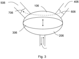
- a membrane pump 60 consists of two chambers 106, 206 separated by a membrane 306.
- the membrane 306 is deformed, thus causing a corresponding pressure/vacuum in the other chamber 206, 106.
- a liquid can be drawn from the low pressure intake duct 406 to send it into the high pressure delivery duct 506, thus utilizing the vacuum and the subsequent pressure caused by the motion of the membrane, as shown by the arrows in the drawing.
- Oil is used to move the membrane, which oil is alternatively introduced/drawn into/from the other chamber 206 by a hydraulic piston pump (not shown). The actuation of the hydraulic pump occurs by means of an electric bel-reduction motor.
- the invention relates to an improvement of the known pumping systems.
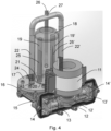
- FIG 4 shows a pumping system 6 according to an embodiment of the present invention.
- the system comprises an electric motor 11 connected by a linkage 12, 12' to a pair of pistons 13, 13' which move coaxially in opposite directions inside corresponding cylinders 14, 14'.
- the cylinders are enclosed in a box-shaped body 15 extending transversely to the cylinders to form a support base for the whole pumping system, the cylinders 14, 14' forming the front part thereof.
- Two separate housings 16, 16' communicating with the corresponding cylinders 14, 14' by means of the box-shaped body 15 are obtained in the rear part of the box-shaped body 15.
- the section of the box-shaped body 15 can be advantageously reduced to reduce the amount of oil required to keep the fluid-dynamic connection between head of the cylinders 14, 14' and corresponding housings 16, 16'.
- Each housing 16, 16' typically cylindrical in shape, is closed at the top by a flange 17, 17' by the interposition of a membrane (not shown in the drawing) so as to form a pair of chambers separated by the membrane itself.
- a membrane not shown in the drawing
- the first chamber adapted to receive the pressurized oil from the corresponding cylinder, is located at the bottom between box-shaped body and membrane, while the second chamber, adapted to draw and send under pressure the mixture containing the refrigerant, is located at the top of the first one, between membrane and closing flange.
- the container 18 of the solution to be pumped is located in median position above the two flanges 17, 17' so as to allow the intake of the contents thereof by means of an intake duct 19, 19' arranged at an opening 20, 20' made on each closing flange 17, 17' to form an intake gap.
- the delivery duct 22, 22' of the output pressurized solution is placed at another opening 23, 23' made on the closing flange 17, 17'. Also in this case, there is a valve 24, 24' between delivery duct 22, 22' and delivery gap 23, 23' for automatically closing the fluid-dynamic delivery circuit when the solution chamber is depressurized.
- the two valves 21, 21' and 24, 24' operate in an opposite manner, i.e., when one opens, the other one closes, to ensure the pumping effect as described above with reference to Figure 3 .
- the circuit is completed with a pair of filters 25, 25' located in the intake ducts 19, 19' and a supplying duct 26 for the solution tank 18.
- the delivery ducts 22, 22' can be kept separate or be joined, as shown in the drawing.
- a T sleeve 27 collects the pressurized fluid output from each chamber.
- the motor(s) 11 advantageously are of the direct drive type, i.e., with load directly connected to the rotor. These motors are capable of delivering variable torques, even at a low number of revolutions, without requiring the use of gear trains or gear motors of any type by virtue of their characterizing electronic control.
- a direct drive motor is a type of synchronous permanent magnet motor which directly actuates the load.
- this type of motor is used, the use of a reducer is eliminated. Therefore, the number of movable components in the system is significantly reduced. This increases the efficiency and creates a silent and highly dynamic operation, as well as a very high duration of the system.
- Examples of direct drive motors are torque motors, linear motors, and certain types of BLDC motors.
- Direct drive motors are highly suitable for applications with significant torque fluctuations. This is because they just need a low torque to accelerate the motor with respect to gear motors, which have a lower torque/inertia ratio.
- Frameless relates to a motor without a frame, housing, bearings, or feedback system. Accordingly, the plant suppliers are capable of integrating their motor in the application itself, eliminating the need for a further interfacing. This obviously decreases the cost of the integrated system.
- a direct drive motor can be used in an absorption heat pump application due to the high torque at low angular speed, small dimensions, small weight, maximum power, presence of driving electronics providing an optimal speed control and useful information on rotor position and absorbed currents.
- the direct drive motor can provide complete control of the electric absorption parameters precisely due to the presence of the electronic control. By connecting such an interface to a control unit, it is possible to read and process said parameters in order to determine the flow conditions of the operating pumping system.
- control unit or a plant control interfaced with the control unit or directly with the motor(s) of the pumping system can advantageously set the operating parameters of the plant based on the flow conditions of the pumping system.
Landscapes
- Engineering & Computer Science (AREA)
- Mechanical Engineering (AREA)
- General Engineering & Computer Science (AREA)
- Physics & Mathematics (AREA)
- Thermal Sciences (AREA)
- Reciprocating Pumps (AREA)
- Sorption Type Refrigeration Machines (AREA)
Claims (7)
- Absorptionswärmepumpenanlage, umfassend einen Generator (1), einen Kondensator (2), ein erstes Expansionsventil (3), einen Verdampfer (4), einen Absorber (5), ein Pumpsystem (6) und ein zweites Expansionsventil (7), die so verbunden sind, dass sie ein Kältemittelgemisch thermodynamischen Absorptionszyklen unterziehen, wobei das Pumpsystem (6) einen Träger (15) umfasst, wobei in dem Träger ein erstes Gehäuse für einen ersten Zylinder (14), in dem ein mit einem Elektromotor (11) verbundener erster Kolben (13) gleitet, und ein zweites Gehäuse (16) für eine erste Membran ausgebildet ist, wobei das zweite Gehäuse (16) durch eine Platte (17) verschlossen ist, wobei die erste Membran das zweite Gehäuse in eine nicht in Verbindung stehende erste Kammer und eine zweite Kammer unterteilt, wobei die erste Kammer mit dem Kopf des ersten Zylinders (14) mittels des Trägers (15) in Verbindung steht, so dass die Hin- und Herbewegung des Kolbens (13) einen Druck/ein Vakuum eines in der ersten Kammer vorhandenen Fluids verursacht, so dass die erste Membran verformt werden kann, wodurch ein entsprechender Druck/ein entsprechendes Vakuum in der zweiten Kammer verursacht wird, wobei die zweite Kammer mit einem ersten Einlasskanal (19) und einem ersten Auslasskanal (22) des Kältemittelgemisches in Verbindung steht, wobei automatische Ventile (21, 24) zum Schließen des ersten Auslasskanals (22), wenn in der zweiten Kammer ein Vakuum erzeugt wird, das dazu geeignet ist, das Kältemittelgemisch anzusaugen, und zum Schließen des ersten Einlasskanals (19) vorgesehen sind, wenn in der zweiten Kammer ein Überdruck erzeugt wird, der dazu geeignet ist, das Kältemittelgemisch in den ersten unter Druck stehenden Auslasskanal (22) zu leiten, dadurch gekennzeichnet, dass der Elektromotor (11) ein Direktantriebsmotor ist, der eine Schnittstelle zum Steuern der elektrischen Absorptionsparameter aufweist, wobei die Schnittstelle mit einer Steuereinheit verbindbar ist, die dazu geeignet ist, die Parameter zu lesen und zu verarbeiten, um die Strömungsbedingungen des im Betrieb befindlichen Pumpsystems zu bestimmen.
- Anlage nach Anspruch 1, wobei ein drittes Gehäuse für eine zweite Membran in dem Träger (15) ausgebildet ist, wobei das dritte Gehäuse durch eine getrennte Platte (17') oder durch dieselbe Platte (17'), die das zweite Gehäuse verschließt, verschlossen wird, wobei die zweite Membran das dritte Gehäuse in eine nicht in Verbindung stehende dritte Kammer und vierte Kammer unterteilt, wobei die dritte Kammer auch mit dem Kopf des ersten Zylinders (14) mittels des Trägers (15) in Verbindung steht, so dass die Hin-und Herbewegung des ersten Kolbens (13), der in dem ersten Zylinder (14) gleitet, einen Druck/ein Vakuum des in der dritten Kammer vorhandenen Fluids verursacht, so dass die zweite Membran verformt werden kann, wodurch ein entsprechender Druck/ein entsprechendes Vakuum in der vierten Kammer erzeugt wird, wobei die vierte Kammer mit einem zweiten Einlasskanal (19') und einem zweiten Auslasskanal (22') für das Kältemittelgemisch in Verbindung steht, wobei automatische Ventile (21', 24') zum Schließen des zweiten Auslasskanals (22'), wenn in der vierten Kammer ein Vakuum erzeugt wird, das dazu geeignet ist, das Kältemittelgemisch anzusaugen, und zum Schließen des zweiten Einlasskanals (19') vorgesehen sind, wenn in der vierten Kammer ein Überdruck erzeugt wird, der dazu geeignet ist, das Kältemittelgemisch in den zweiten unter Druck stehenden Auslasskanal (22') zu leiten.
- Anlage nach Anspruch 2, wobei ein viertes Gehäuse für einen zweiten Zylinder (14'), in dessen Inneren ein zweiter Kolben (13'), der mit einem Direktantriebsmotor (11) verbunden ist, gleitet, in dem Träger ausgebildet ist, wobei der Kopf des zweiten Zylinders (14') mit der dritten Kammer in Verbindung steht, wobei die dritte Kammer nicht mit der ersten Kammer in Verbindung steht, so dass die Hin- und Herbewegung des zweiten Kolbens (13') einen Druck/ein Vakuum eines in der dritten Kammer vorhandenen Fluids verursacht, so dass die zweite Membran verformt werden kann, wodurch ein entsprechender Druck/ein entsprechendes Vakuum in der vierten Kammer verursacht wird.
- Anlage nach Anspruch 2 oder 3, wobei der erste und zweite Auslasskanal (22, 22') mit demselben Ablassstutzen (27) in Verbindung stehen.
- Anlage nach einem oder mehreren der vorhergehenden Ansprüche, wobei ein Behälter (18) für die zu pumpende Lösung an der Platte (17) vorhanden ist, um das Ansaugen des Inhalts mittels der Einlasskanäle (19, 19') zu ermöglichen, die an Öffnungen (20, 20') angeordnet sind, die in der Verschlussplatte (17) zur Bildung von Einlassspalten ausgebildet sind.
- Anlage nach einem oder mehreren der vorhergehenden Ansprüche, wobei der Kolben oder die Kolben (13, 13') mittels eines Gestänges (12, 12') mit dem Elektromotor (11) verbunden sind.
- Anlage nach einem oder mehreren der vorhergehenden Ansprüche, umfassend eine Steuereinheit zum Einstellen der Betriebsparameter der Anlage, wobei die Steuereinheit über eine Schnittstelle mit der Steuereinheit des Pumpsystems verbunden ist oder die Steuereinheit ersetzt, um die fluiddynamischen Parameter des Pumpsystems zu erfassen und entsprechend auf die Anlagenkomponenten einzuwirken.
Applications Claiming Priority (1)
| Application Number | Priority Date | Filing Date | Title |
|---|---|---|---|
| IT102021000021521A IT202100021521A1 (it) | 2021-08-09 | 2021-08-09 | Sistema di pompaggio per circuiti a pompe di calore ad assorbimento |
Publications (3)
| Publication Number | Publication Date |
|---|---|
| EP4134547A1 EP4134547A1 (de) | 2023-02-15 |
| EP4134547B1 true EP4134547B1 (de) | 2024-12-11 |
| EP4134547C0 EP4134547C0 (de) | 2024-12-11 |
Family
ID=78649683
Family Applications (1)
| Application Number | Title | Priority Date | Filing Date |
|---|---|---|---|
| EP22188683.1A Active EP4134547B1 (de) | 2021-08-09 | 2022-08-04 | Pumpensystem für absorptionswärmepumpenkreisläufe |
Country Status (4)
| Country | Link |
|---|---|
| US (1) | US20230052969A1 (de) |
| EP (1) | EP4134547B1 (de) |
| CN (1) | CN115704614A (de) |
| IT (1) | IT202100021521A1 (de) |
Families Citing this family (1)
| Publication number | Priority date | Publication date | Assignee | Title |
|---|---|---|---|---|
| CN117739544B (zh) * | 2024-02-19 | 2024-05-14 | 浙江飞旋科技有限公司 | 一种制冷制热系统、工作方法及空调 |
Family Cites Families (10)
| Publication number | Priority date | Publication date | Assignee | Title |
|---|---|---|---|---|
| US4483154A (en) * | 1980-04-14 | 1984-11-20 | Smeal William J | Refrigerated air conditioning system using diaphragm pump |
| US4975026A (en) * | 1989-02-17 | 1990-12-04 | Energy Innovations, Inc. | Free-piston heat pump |
| DE69114474T2 (de) * | 1991-04-19 | 1996-08-08 | Enea Ente Nuove Tec | Einführvorrichtung einer Kolbenpumpe für Saturationsflüssigkeiten. |
| US5616012A (en) * | 1995-08-31 | 1997-04-01 | Hillman; Darrel D. | Ammonia pump |
| US5624246A (en) * | 1995-09-25 | 1997-04-29 | Gas Research Institute | Hydraulic ammonia solution pump |
| US6099269A (en) * | 1997-10-06 | 2000-08-08 | Fin Robur | Absorption refrigeration system having a diaphragm pump and a hydraulic piston pump |
| US6564562B1 (en) * | 2002-01-10 | 2003-05-20 | American Standard International Inc. | Generator solution outlet box for an absorption chiller |
| US6705111B1 (en) * | 2003-01-09 | 2004-03-16 | Rocky Research | Ammonia-water absorption system with plunger-driven diaphragm solution pump |
| IL177020A0 (en) * | 2006-07-23 | 2006-12-10 | Totec Ltd Top Technologies | Absorption cooling system |
| US10774830B2 (en) * | 2018-04-03 | 2020-09-15 | Graco Minnesota Inc. | Self-lubricating pump throat seal |
-
2021
- 2021-08-09 IT IT102021000021521A patent/IT202100021521A1/it unknown
-
2022
- 2022-08-04 EP EP22188683.1A patent/EP4134547B1/de active Active
- 2022-08-05 US US17/817,916 patent/US20230052969A1/en not_active Abandoned
- 2022-08-09 CN CN202210951286.6A patent/CN115704614A/zh active Pending
Also Published As
| Publication number | Publication date |
|---|---|
| CN115704614A (zh) | 2023-02-17 |
| EP4134547C0 (de) | 2024-12-11 |
| EP4134547A1 (de) | 2023-02-15 |
| IT202100021521A1 (it) | 2023-02-09 |
| US20230052969A1 (en) | 2023-02-16 |
Similar Documents
| Publication | Publication Date | Title |
|---|---|---|
| EP2673507B1 (de) | Gasförmige fluidverdichtungsvorrichtung | |
| KR101332461B1 (ko) | 동력 발생 장치 | |
| EP1592875B1 (de) | Stirlingmotorbetriebene wärmepumpe mit fluidverbindung | |
| US3823573A (en) | Automotive air conditioning apparatus | |
| CN102265002A (zh) | 克劳修斯-朗肯循环回路 | |
| WO1988009906A1 (en) | Energy recovery apparatus | |
| EP4134547B1 (de) | Pumpensystem für absorptionswärmepumpenkreisläufe | |
| DE102007042791A1 (de) | Pumpe oder Kompressor | |
| JPH0886289A (ja) | ローリングピストン式回転機械 | |
| US9746215B2 (en) | Heat powered reciprocating piston engine | |
| US3473347A (en) | Refrigeration system employing bellows solution pump | |
| US4383418A (en) | Circulator pump for conveying a liquid and/or gaseous medium | |
| EP2775128A1 (de) | Abwärmerückgewinnungssystem | |
| WO2014012586A1 (en) | Heat to mechanical energy converter | |
| US4902207A (en) | Energy recovery apparatus | |
| GB2090645A (en) | A positive displacement device | |
| EP0048139A1 (de) | Pumpeinrichtung | |
| CN105221432A (zh) | 具有有机朗肯循环的螺杆压缩机系统 | |
| JP5272941B2 (ja) | ターボ圧縮機及び冷凍機 | |
| JP2005248889A (ja) | 液体ポンプ及びランキンサイクル装置 | |
| JP4736637B2 (ja) | 液体ポンプ及びランキンサイクル装置 | |
| US9447704B2 (en) | Heat recovery system for an internal combustion engine | |
| JP2005171819A (ja) | 冷媒圧縮機 | |
| US634335A (en) | Apparatus for ice-making, &c. | |
| CN113661307B (zh) | 发电系统和通过操作这种发电系统来发电的方法 |
Legal Events
| Date | Code | Title | Description |
|---|---|---|---|
| PUAI | Public reference made under article 153(3) epc to a published international application that has entered the european phase |
Free format text: ORIGINAL CODE: 0009012 |
|
| STAA | Information on the status of an ep patent application or granted ep patent |
Free format text: STATUS: THE APPLICATION HAS BEEN PUBLISHED |
|
| AK | Designated contracting states |
Kind code of ref document: A1 Designated state(s): AL AT BE BG CH CY CZ DE DK EE ES FI FR GB GR HR HU IE IS IT LI LT LU LV MC MK MT NL NO PL PT RO RS SE SI SK SM TR |
|
| P01 | Opt-out of the competence of the unified patent court (upc) registered |
Effective date: 20230525 |
|
| STAA | Information on the status of an ep patent application or granted ep patent |
Free format text: STATUS: REQUEST FOR EXAMINATION WAS MADE |
|
| 17P | Request for examination filed |
Effective date: 20230809 |
|
| RBV | Designated contracting states (corrected) |
Designated state(s): AL AT BE BG CH CY CZ DE DK EE ES FI FR GB GR HR HU IE IS IT LI LT LU LV MC MK MT NL NO PL PT RO RS SE SI SK SM TR |
|
| GRAP | Despatch of communication of intention to grant a patent |
Free format text: ORIGINAL CODE: EPIDOSNIGR1 |
|
| STAA | Information on the status of an ep patent application or granted ep patent |
Free format text: STATUS: GRANT OF PATENT IS INTENDED |
|
| INTG | Intention to grant announced |
Effective date: 20240701 |
|
| GRAS | Grant fee paid |
Free format text: ORIGINAL CODE: EPIDOSNIGR3 |
|
| GRAA | (expected) grant |
Free format text: ORIGINAL CODE: 0009210 |
|
| STAA | Information on the status of an ep patent application or granted ep patent |
Free format text: STATUS: THE PATENT HAS BEEN GRANTED |
|
| AK | Designated contracting states |
Kind code of ref document: B1 Designated state(s): AL AT BE BG CH CY CZ DE DK EE ES FI FR GB GR HR HU IE IS IT LI LT LU LV MC MK MT NL NO PL PT RO RS SE SI SK SM TR |
|
| REG | Reference to a national code |
Ref country code: GB Ref legal event code: FG4D |
|
| REG | Reference to a national code |
Ref country code: CH Ref legal event code: EP |
|
| REG | Reference to a national code |
Ref country code: DE Ref legal event code: R096 Ref document number: 602022008561 Country of ref document: DE |
|
| REG | Reference to a national code |
Ref country code: IE Ref legal event code: FG4D |
|
| U01 | Request for unitary effect filed |
Effective date: 20241219 |
|
| U07 | Unitary effect registered |
Designated state(s): AT BE BG DE DK EE FI FR IT LT LU LV MT NL PT RO SE SI Effective date: 20250110 |
|
| P04 | Withdrawal of opt-out of the competence of the unified patent court (upc) registered |
Free format text: CASE NUMBER: APP_1216/2025 Effective date: 20250108 |
|
| PG25 | Lapsed in a contracting state [announced via postgrant information from national office to epo] |
Ref country code: HR Free format text: LAPSE BECAUSE OF FAILURE TO SUBMIT A TRANSLATION OF THE DESCRIPTION OR TO PAY THE FEE WITHIN THE PRESCRIBED TIME-LIMIT Effective date: 20241211 |
|
| PG25 | Lapsed in a contracting state [announced via postgrant information from national office to epo] |
Ref country code: ES Free format text: LAPSE BECAUSE OF FAILURE TO SUBMIT A TRANSLATION OF THE DESCRIPTION OR TO PAY THE FEE WITHIN THE PRESCRIBED TIME-LIMIT Effective date: 20241211 |
|
| PG25 | Lapsed in a contracting state [announced via postgrant information from national office to epo] |
Ref country code: NO Free format text: LAPSE BECAUSE OF FAILURE TO SUBMIT A TRANSLATION OF THE DESCRIPTION OR TO PAY THE FEE WITHIN THE PRESCRIBED TIME-LIMIT Effective date: 20250311 |
|
| PG25 | Lapsed in a contracting state [announced via postgrant information from national office to epo] |
Ref country code: GR Free format text: LAPSE BECAUSE OF FAILURE TO SUBMIT A TRANSLATION OF THE DESCRIPTION OR TO PAY THE FEE WITHIN THE PRESCRIBED TIME-LIMIT Effective date: 20250312 |
|
| PG25 | Lapsed in a contracting state [announced via postgrant information from national office to epo] |
Ref country code: RS Free format text: LAPSE BECAUSE OF FAILURE TO SUBMIT A TRANSLATION OF THE DESCRIPTION OR TO PAY THE FEE WITHIN THE PRESCRIBED TIME-LIMIT Effective date: 20250311 |
|
| PG25 | Lapsed in a contracting state [announced via postgrant information from national office to epo] |
Ref country code: SM Free format text: LAPSE BECAUSE OF FAILURE TO SUBMIT A TRANSLATION OF THE DESCRIPTION OR TO PAY THE FEE WITHIN THE PRESCRIBED TIME-LIMIT Effective date: 20241211 |
|
| PG25 | Lapsed in a contracting state [announced via postgrant information from national office to epo] |
Ref country code: PL Free format text: LAPSE BECAUSE OF FAILURE TO SUBMIT A TRANSLATION OF THE DESCRIPTION OR TO PAY THE FEE WITHIN THE PRESCRIBED TIME-LIMIT Effective date: 20241211 |
|
| PG25 | Lapsed in a contracting state [announced via postgrant information from national office to epo] |
Ref country code: IS Free format text: LAPSE BECAUSE OF FAILURE TO SUBMIT A TRANSLATION OF THE DESCRIPTION OR TO PAY THE FEE WITHIN THE PRESCRIBED TIME-LIMIT Effective date: 20250411 |
|
| PG25 | Lapsed in a contracting state [announced via postgrant information from national office to epo] |
Ref country code: SK Free format text: LAPSE BECAUSE OF FAILURE TO SUBMIT A TRANSLATION OF THE DESCRIPTION OR TO PAY THE FEE WITHIN THE PRESCRIBED TIME-LIMIT Effective date: 20241211 |
|
| PG25 | Lapsed in a contracting state [announced via postgrant information from national office to epo] |
Ref country code: CZ Free format text: LAPSE BECAUSE OF FAILURE TO SUBMIT A TRANSLATION OF THE DESCRIPTION OR TO PAY THE FEE WITHIN THE PRESCRIBED TIME-LIMIT Effective date: 20241211 |
|
| U20 | Renewal fee for the european patent with unitary effect paid |
Year of fee payment: 4 Effective date: 20250709 |
|
| PLBE | No opposition filed within time limit |
Free format text: ORIGINAL CODE: 0009261 |
|
| STAA | Information on the status of an ep patent application or granted ep patent |
Free format text: STATUS: NO OPPOSITION FILED WITHIN TIME LIMIT |
|
| 26N | No opposition filed |
Effective date: 20250912 |