EP4134491A1 - Nivellierungssteuerungsverfahren, -vorrichtung und -system sowie motorgrader - Google Patents
Nivellierungssteuerungsverfahren, -vorrichtung und -system sowie motorgrader Download PDFInfo
- Publication number
- EP4134491A1 EP4134491A1 EP21763932.7A EP21763932A EP4134491A1 EP 4134491 A1 EP4134491 A1 EP 4134491A1 EP 21763932 A EP21763932 A EP 21763932A EP 4134491 A1 EP4134491 A1 EP 4134491A1
- Authority
- EP
- European Patent Office
- Prior art keywords
- gps
- elevation
- target position
- motor grader
- leveling control
- Prior art date
- Legal status (The legal status is an assumption and is not a legal conclusion. Google has not performed a legal analysis and makes no representation as to the accuracy of the status listed.)
- Granted
Links
Images


Classifications
-
- E—FIXED CONSTRUCTIONS
- E02—HYDRAULIC ENGINEERING; FOUNDATIONS; SOIL SHIFTING
- E02F—DREDGING; SOIL-SHIFTING
- E02F3/00—Dredgers; Soil-shifting machines
- E02F3/04—Dredgers; Soil-shifting machines mechanically-driven
- E02F3/76—Graders, bulldozers, or the like with scraper plates or ploughshare-like elements; Levelling scarifying devices
- E02F3/80—Component parts
- E02F3/84—Drives or control devices therefor, e.g. hydraulic drive systems
- E02F3/841—Devices for controlling and guiding the whole machine, e.g. by feeler elements and reference lines placed exteriorly of the machine
- E02F3/842—Devices for controlling and guiding the whole machine, e.g. by feeler elements and reference lines placed exteriorly of the machine using electromagnetic, optical or photoelectric beams, e.g. laser beams
-
- E—FIXED CONSTRUCTIONS
- E02—HYDRAULIC ENGINEERING; FOUNDATIONS; SOIL SHIFTING
- E02F—DREDGING; SOIL-SHIFTING
- E02F3/00—Dredgers; Soil-shifting machines
- E02F3/04—Dredgers; Soil-shifting machines mechanically-driven
- E02F3/76—Graders, bulldozers, or the like with scraper plates or ploughshare-like elements; Levelling scarifying devices
- E02F3/7636—Graders with the scraper blade mounted under the tractor chassis
- E02F3/764—Graders with the scraper blade mounted under the tractor chassis with the scraper blade being pivotable about a vertical axis
-
- E—FIXED CONSTRUCTIONS
- E02—HYDRAULIC ENGINEERING; FOUNDATIONS; SOIL SHIFTING
- E02F—DREDGING; SOIL-SHIFTING
- E02F3/00—Dredgers; Soil-shifting machines
- E02F3/04—Dredgers; Soil-shifting machines mechanically-driven
- E02F3/76—Graders, bulldozers, or the like with scraper plates or ploughshare-like elements; Levelling scarifying devices
- E02F3/80—Component parts
- E02F3/815—Blades; Levelling or scarifying tools
- E02F3/8152—Attachments therefor, e.g. wear resisting parts, cutting edges
-
- E—FIXED CONSTRUCTIONS
- E02—HYDRAULIC ENGINEERING; FOUNDATIONS; SOIL SHIFTING
- E02F—DREDGING; SOIL-SHIFTING
- E02F3/00—Dredgers; Soil-shifting machines
- E02F3/04—Dredgers; Soil-shifting machines mechanically-driven
- E02F3/76—Graders, bulldozers, or the like with scraper plates or ploughshare-like elements; Levelling scarifying devices
- E02F3/80—Component parts
- E02F3/84—Drives or control devices therefor, e.g. hydraulic drive systems
- E02F3/844—Drives or control devices therefor, e.g. hydraulic drive systems for positioning the blade, e.g. hydraulically
- E02F3/847—Drives or control devices therefor, e.g. hydraulic drive systems for positioning the blade, e.g. hydraulically using electromagnetic, optical or acoustic beams to determine the blade position, e.g. laser beams
-
- E—FIXED CONSTRUCTIONS
- E02—HYDRAULIC ENGINEERING; FOUNDATIONS; SOIL SHIFTING
- E02F—DREDGING; SOIL-SHIFTING
- E02F3/00—Dredgers; Soil-shifting machines
- E02F3/04—Dredgers; Soil-shifting machines mechanically-driven
- E02F3/76—Graders, bulldozers, or the like with scraper plates or ploughshare-like elements; Levelling scarifying devices
- E02F3/80—Component parts
- E02F3/84—Drives or control devices therefor, e.g. hydraulic drive systems
- E02F3/844—Drives or control devices therefor, e.g. hydraulic drive systems for positioning the blade, e.g. hydraulically
- E02F3/848—Drives or control devices therefor, e.g. hydraulic drive systems for positioning the blade, e.g. hydraulically using cable drums
Definitions
- the present disclosure relates to the field of construction machinery, in particular to a leveling control method, apparatus and system, a motor grader and a computer storable medium.
- the motor grader is an earth moving construction machine which uses a shovel blade as a main body and cooperates with other various replaceable operation devices to carry out a soil shoveling, leveling or shaping operation.
- the motor grader is mainly applied to large-area leveling operations of soil such as roads, airports, farmlands, water conservancy and the like, and construction operation scenes such as slope scraping, ditching, bulldozing, soil loosening, road ice and snow clearing and the like.
- the motor grader is one of important equipment in national defense construction, traffic and water conservancy basic construction, and plays a great role in national economic construction.
- leveling control systems for the motor grader: one is a laser-based leveling control System, and the other is a GPS (Global Positioning System)-based three-dimensional leveling system.
- the GPS has advantages of high precision and all-weather measurement, and can accurately detect the elevation of the shovel blade in the leveling process of the motor grader to realize a precise leveling operation of the road surface. Accordingly, GPS is typically utilized in the leveling control systems of the motor grader to detect the elevation of the shovel blade.
- the GPS is arranged at both ends of the shovel blade of the motor grader to acquire the elevation of the shovel blade in real time, which is compared with a preset elevation of the earth's surface, to adjust a lifting oil cylinder in real time according to a difference obtained through the comparison, so as to realize the control of the elevation of the shovel blade.
- a leveling control method comprising: respectively acquiring an elevation of a current position of a shovel blade of a motor grader, an elevation of a target position, and a movement speed of the motor grader, wherein the target position is on the ground with a certain horizontal distance from the current position along a movement direction of the motor grader; determining a movement time of the shovel blade from the current position to the target position according to the horizontal distance and the movement speed; determining a lifting speed of a lifting oil cylinder according to an elevation difference between the elevation of the target position and the elevation of the current position and the movement time; and controlling the lifting oil cylinder to adjust the shovel blade to move from the current position to the target position according to the lifting speed.
- acquiring an elevation of a target position comprises: respectively acquiring an elevation of a Global Positioning System GPS and a vertical distance between the GPS and the target position, wherein the (GPS) is fixedly arranged relative to a frame of the motor grader; and acquiring the elevation of the target position according to the elevation of the GPS and the vertical distance between the GPS and the target position.
- GPS Global Positioning System
- acquiring a vertical distance between the GPS and the target position comprises: acquiring a vertical distance between a distance sensor and the target position, wherein the distance sensor is fixedly arranged relative to the frame of the motor grader; acquiring a vertical distance between the GPS and the distance sensor; and acquiring the vertical distance between the GPS and the target position according to the vertical distance between the distance sensor and the target position and the vertical distance between the GPS and the distance sensor.
- the distance sensor is located directly above the target position, and acquiring a vertical distance between a distance sensor and the target position comprises: acquiring a detection value obtained by the distance sensor through detecting the ground; and acquiring the vertical distance between the distance sensor and the target position according to the detection value.
- the distance sensor is an ultrasonic sensor or a lidar sensor
- acquiring the vertical distance between the distance sensor and the target position according to the detection value comprises: determining the detection value as the vertical distance between the distance sensor and the target position in the case that the distance sensor is the ultrasonic sensor; and determining a product of the detection value and a cosine value of a laser emission angle of the lidar sensor as the vertical distance between the distance sensor and the target position in the case that the distance sensor is the lidar sensor.
- acquiring an elevation of a current position of a shovel blade of a motor grader comprises: acquiring an elevation of a Global Positioning System (GPS), wherein the GPS is fixedly arranged relative to a frame of the motor grader; and acquiring the elevation of the current position of the shovel blade of the motor grader according to the elevation of the GPS.
- GPS Global Positioning System
- the GPS is located directly above the shovel blade, and acquiring the elevation of the current position of the shovel blade of the motor grader according to the elevation of the global positioning system (GPS) comprises: determining an elevation of a projection point of the GPS on the ground according to a distance between the GPS and the projection point of the GPS on the ground and the elevation of the GPS; and determining the elevation of the current position of the shovel blade according to the elevation of the projection point of the GPS on the ground and a shovel angle of the current position of the shovel blade.
- GPS global positioning system
- the current position includes a position of a first edge angle and a position of a second edge angle of the shovel blade, respectively.
- a leveling control apparatus comprising: an acquiring module configured to respectively acquire an elevation of a current position of a shovel blade of a motor grader, an elevation of a target position, and a movement speed of the motor grader, wherein the target position is on the ground with a certain horizontal distance from the current position along a movement direction of the motor grader; a first determining module configured to determine a movement time of the shovel blade from the current position to the target position according to the horizontal distance and the movement speed; a second determining module configured to determine a lifting speed of a lifting oil cylinder according to an elevation difference between the elevation of the target position and the elevation of the current position and the movement time; and a controlling module configured to control the lifting oil cylinder to adjust the shovel blade to move from the current position to the target position according to the lifting speed.
- a leveling control apparatus comprising: a memory; and a processor coupled to the memory, the processor configured to perform the leveling control method according to any of the above embodiments based on instructions stored in the memory.
- a leveling control system comprising: the leveling control apparatus according to any of the above embodiments.
- the leveling control system further comprises: a speed sensor arranged on any wheel of the motor grader, configured to measure a movement speed of the motor grader and send the movement speed to the leveling control apparatus; and a Global Positioning System (GPS) fixedly arranged relative to a frame of the motor grader, configured to measure an elevation of the GPS and send the elevation of the GPS to the leveling control apparatus; and a distance sensor fixedly arranged relative to a frame of the motor grader, configured to detect the ground to get a detection value and send the detection value to the leveling control apparatus.
- GPS Global Positioning System
- the GPS and the distance sensor are fixedly arranged relative to the frame of the motor grader by a first bracket and a second bracket, respectively.
- the GPS is located directly above the shovel blade, and the distance sensor is spaced apart from the shovel blade by a certain distance along the movement direction of the motor grader.
- the first bracket is perpendicular to a horizontal plane and the second bracket is parallel to the horizontal plane.
- the GPS includes a first GPS and a second GPS, respectively located directly above the shovel blade on both sides in a width direction of a body of the motor grader; and the distance sensor includes a first distance sensor and a second distance sensor respectively spaced apart from the both sides along the movement direction of the motor grader by a certain distance, and the first distance sensor and the first GPS are both located on one side of the both sides, and the second distance sensor and the second GPS are both located on the other side of the both sides.
- a motor grader comprising: the leveling control system according to any of the above embodiments.
- a computer storable medium having stored thereon computer program instructions which, when executed by a processor, implement the leveling control method according to any of the above embodiments.
- a hydraulic system of the motor grader has hysteresis, i.e. , a certain time is required from the acquisition of the elevation of the shovel blade to the actual adjustment of the shovel blade to a preset elevation.
- the motor grader always operates at a certain speed, and the horizontal position of the shovel blade has changed when the shovel blade is adjusted to the preset elevation, resulting a poor leveling accuracy.
- the present disclosure provides a leveling control method, which improves leveling accuracy.
- FIG. 1 is a flow chart illustrating a leveling control method according to some embodiments of the present disclosure.
- FIG. 2 is a schematic diagram illustrating a side view of a leveling control system according to some embodiments of the present disclosure.
- FIG. 3a is a schematic diagram illustrating a structure of a leveling control system according to some embodiments of the present disclosure.
- FIG. 3b is a schematic diagram illustrating a structure of a leveling control system according to some other embodiments of the present disclosure.
- the leveling control method comprises step S110: respectively acquiring an elevation of a current position of a shovel blade of a motor grader, an elevation of a target position and a movement speed of the motor grader; step S120: determining a movement time of the shovel blade from the current position to the target position; step S130: determining a lifting speed of a lifting oil cylinder; and step S140: controlling the lifting oil cylinder to adjust the shovel blade to move from the current position to the target position according to the lifting speed.
- the motor grader includes, but is not limited to, construction motor grader and agricultural motor grader.
- the lifting speed of the shovel blade is determined according to the elevation of the current position of the shovel blade, the elevation of the target position and the movement speed of the motor grader, so that when the shovel blade of the motor grader moves horizontally from the current position to the target position, the elevation of the shovel blade changes from the elevation of the current position to the elevation of the target position, and the elevation of the shovel blade keeps consistent with the actual elevation of the target position, which realizes the accurate control of the elevation of the shovel blade, improves the leveling accuracy, and reduces an error between the adjusted elevation of the shovel blade and an actual elevation of the ground position caused by the hysteresis of the hydraulic system.
- step S110 the elevation of the current position of the shovel blade of the motor grader, the elevation of the target position, and the movement speed of the motor grader are acquired, respectively.
- the target position is on the ground with a certain horizontal distance from the current position along a movement direction of the motor grader.
- the current position of the shovel blade 210 is A and the target position is B.
- the horizontal distance between A and B is denoted L.
- a shovel angle of the shovel blade 210 at the current position A is ⁇ .
- FIG. 4a is a flow chart illustrating acquiring an elevation of a target position according to some embodiments of the present disclosure.
- FIG. 4b is a schematic diagram illustrating acquiring a vertical distance between a distance sensor and the target position according to some embodiments of the present disclosure.
- FIG. 4c is a schematic diagram illustrating acquiring a vertical distance between a distance sensor and the target position according to some other embodiments of the present disclosure.
- that acquiring the elevation of the target position comprises steps S111 and S112.
- step S111 an elevation of GPS and a vertical distance between the GPS and the target position are acquired, respectively.
- the GPS is a GPS receiver.
- the elevation of the GPS is a measurement Z GPS of the GPS.
- the GPS 211 in FIG. 3a is fixedly arranged relative to a frame 212 of the motor grader.
- the GPS 211 is fixedly arranged relative to the frame 212 of the motor grader via a first bracket 213.
- the step S111 of acquiring the vertical distance between the GPS and the target position, shown in FIG. 4a is achieved for example in the following manner.
- a vertical distance between the distance sensor and the target position is acquired.
- the distance sensor 214 is located directly above the target position B.
- the distance sensor 214 is fixedly arranged relative to the frame 212 of the motor grader.
- the distance sensor 214 is spaced apart from the shovel blade 210 by a certain distance along the movement direction of the motor grader. The distance may be set empirically.
- the vertical distance between the distance sensor and the target position is the distance between the distance sensor and the target position.
- the distance sensor is an ultrasonic sensor or a lidar sensor.
- the detection value is determined as the vertical distance between the distance sensor and the target position.
- the distance sensor 214 is an ultrasonic sensor.
- the position of the ground detected by the ultrasonic sensor is the target position B.
- the vertical distance H 1 between the ultrasonic sensor and the target position B is the detection value.
- the distance sensor 214 is fixedly disposed at an end of a second bracket 215.
- the distance sensor is a lidar sensor
- a product of the detection value and a cosine value of a laser emission angle of the lidar sensor is determined as the vertical distance between the distance sensor and the target position.
- the distance sensor 214 is a lidar sensor.
- the position of the ground detected by the lidar sensor is a detection position D with a certain horizontal distance from the target position B on the ground.
- the detection value is a distance S between the lidar sensor and the detection position D.
- the laser emission angle of the lidar sensor is ⁇ .
- the laser emission angle is also referred to as a detection angle.
- the distance sensor 214 is fixedly disposed at an end of the second bracket 215.
- a triangle formed by a connecting line between the lidar sensor and the detection position D, a connecting line between the lidar sensor and the target position B and a connecting line between the target position B and the detection position D can be approximately regarded as a right-angled triangle.
- the vertical distance H 1 between the distance sensor and the target position is S ⁇ cos ⁇ .
- the lidar sensor is more accurate when being used in a secondary levelling scene.
- the vertical distance between the distance sensor and the target position is acquired.
- the distance sensor 214 is fixedly arranged relative to the frame 212 of the motor grader.
- the GPS 211 is located directly above the shovel blade 210.
- the first bracket 213 is perpendicular to the horizontal plane and the second bracket 215 is parallel to the horizontal plane.
- the GPS 211 is disposed at an end of the first bracket 213 away from the shovel blade 210
- the distance sensor 214 is disposed at an end of the second bracket 215 away from the shovel blade 210.
- the first bracket 213 has a length L 1 .
- the vertical distance between the GPS and the distance sensor is L 1 .
- the horizontal plane in the present disclosure is a reference plane for measuring the elevation.
- the frame 212 of the motor grader includes a third bracket 2121.
- the third bracket 2121 is located directly above the shovel blade 210, in parallel with an upper edge of the shovel blade 210.
- the upper edge of the shovel blade 210 is an edge connected to a rotating shaft 216.
- the GPS 211 and the distance sensor 214 are fixedly arranged relative to the third bracket 2121 via the first bracket 213 and the second bracket 215, respectively.
- the fixed connection mode between the first bracket 213, the second bracket 215 and the third bracket 2121 is a bolt fixed connection or a welding fixed connection.
- the third bracket 2121 is a connecting plate.
- the length of the connecting plate can be set as needed.
- the vertical distance between the GPS and the target position is acquired according to the vertical distance between the distance sensor and the target position and the vertical distance between the GPS and the distance sensor.
- the vertical distance H 2 between the GPS 211 and the target position B is a sum of H 1 and L 1 .
- step S112 the elevation of the target position is acquired according to the elevation of the GPS and the vertical distance between the GPS and the target position.
- the elevation Z B of the target position B is Z GPS -(H 1 +L 1 ).
- step S110 the description of the step S110 is continued.
- FIG. 5 is a flow chart illustrating acquiring an elevation of a current position of a blade of a motor grader according to some embodiments of the present disclosure.
- that acquiring the elevation of the current position of the shovel blade of the motor grader comprises steps S113-S114.
- step S113 the elevation of the GPS is acquired.
- the elevation Z GPS of the GPS 211 in FIG. 2 is acquired.
- step S114 the elevation of the current position of the shovel blade of the motor grader is acquired according to the elevation of the GPS.
- the GPS 211 is located directly above the shovel blade 210.
- the elevation of the current position of the shovel blade of the motor grader is obtained according to the elevation of the GPS in the following manner.
- the elevation of a projection point of the GPS on the ground is determined according to the distance between the GPS and the projection point of the GPS on the ground and the elevation of the GPS.
- the elevation of the GPS 211 is Z GPS .
- a shovel blade chord length of the shovel blade 210 is L 2 .
- the shovel blade chord length of the shovel blade 210 is a length of a vertical line segment between an upper edge and a lower edge of the shovel blade 210.
- the lower edge of the shovel blade is an edge close to the ground opposite the upper edge of the shovel blade.
- a position of any edge angle of the lower edge of the shovel blade is a projection point of the GPS 211 on the ground.
- a distance between the GPS 211 and a projection point C of the GPS 211 on the ground is a sum of L 1 and L 2 wherein L 1 is the length of the first bracket.
- the elevation Z C of the projection point C of the GPS 211 on the ground is Z GPS -(L 1 +L 2 ).
- the elevation of the current position of the shovel blade is determined according to the elevation of the projection point of the GPS on the ground and a shovel angle of the current position of the shovel blade.
- the shovel angle of the current position A of the shovel blade 210 is ⁇ .
- the shovel blade 210 is coupled to the rotating shaft 216, and the shovel blade 210 may be rotated clockwise or counterclockwise about the rotating shaft 216 to form the shovel angle shown in FIG. 2 .
- a radius of rotation of the shovel blade 210 is the shovel blade chord length L 2 .
- the shovel blade chord length is a length of a vertical line segment between the upper edge and the lower edge of the shovel blade. L 2 can be obtained by measurement.
- the GPS includes a first GPS 211a and a second GPS 211b.
- the first GPS 211a and the second GPS 211b are respectively located on both sides of the shovel blade 210 in a width direction of a body of the motor grader.
- the first GPS 211a and the second GPS 211b are fixedly arranged relative to the third bracket 2121 via the first bracket 213a and the first bracket 213b, respectively.
- the distance sensors include a first distance sensor 214a and a second distance sensor 214b.
- the first and second distance sensors 214a and 214b are spaced apart from both sides by a certain horizontal distance, respectively, along the movement direction of the motor grader.
- the first distance sensor 214a and the first GPS 211a are both located on one side of both sides.
- the second distance sensor 214b and the second GPS 211b are both located on the other side of both sides.
- the first and second distance sensors 214a and 214b are fixedly arranged relative to the third bracket 2121 via the second bracket 215a and the second bracket 215b, respectively.
- Specific positions of the two GPS and the two distance sensors on both sides of the body in the width direction may be set as required.
- the current position includes a position of a first edge angle and a position of a second edge angle of the shovel blade.
- the position of the first edge angle is 2101a and the position of the second edge angle is 2101b.
- step S110 the description of the step S110 is continued.
- the step S110 of acquiring the movement speed of the motor grader is realized in the following manner for example.
- the movement speed v of the motor grader is acquired by a speed sensor provided on any one wheel of the motor grader.
- step S120 is continuously performed.
- the movement time of the shovel blade from the current position to the target position is determined according to the horizontal distance and the movement speed.
- the second bracket 215 has a length L 3 .
- the shovel angle at the current position A of the shovel blade 210 is ⁇ .
- the angle ⁇ of rotation of the shovel blade from the projection point C to the current position A is 2 ⁇ .
- the horizontal distance L is L 3 +L 2 ⁇ sin2 ⁇ .
- ⁇ takes a negative value.
- ⁇ takes a positive value.
- the movement time t of the shovel blade 210 from the current position A to the target position B in FIG. 2 is L/v, as can be learned from the physical kinematics.
- the lifting speed of the lifting oil cylinder is determined according to an elevation difference between the elevation of the target position and the elevation of the current position and the movement time.
- the elevation Z B of the target position B is Z GPS - (H 1 + L 1 ), and the elevation Z A of the current position A is Z GPS -(L 1 +L 2 ) + (L 2 -L 2 ⁇ cos(2 ⁇ ) ).
- Z B -Z A is the elevation difference.
- the elevation difference is positive, negative or 0.
- lifting oil cylinders 217a and 217b in FIG. 3a both have a lifting speed of (Z B -Z A ) ⁇ (L/v).
- the lifting speed is positive, negative or 0 corresponding to the elevation difference.
- the lifting speed of the first lifting oil cylinder 217a and the lifting speed of the second lifting oil cylinder 217b may be separately determined using a similar calculation process .
- the lifting oil cylinder is controlled to adjust the shovel blade to move from the current position to the target position according to the lifting speed.
- the lifting oil cylinder is controlled to adjust the shovel blade to rise from the current position according to the lifting speed so as to reach the target position.
- the target position is lower than the current position, and the lifting oil cylinder is controlled to adjust the shovel blade to fall from the current position according to the lifting speed so as to reach the target position.
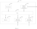
- Fig. 6 is a block diagram illustrating a controller according to some embodiments of the present disclosure.
- the controller 610 comprises a first acquiring module 611, a second acquiring module 612, a third acquiring module 613, a first determining module 614, a second determining module 615, and a control module 616.
- the controller 610 is a leveling control apparatus.
- the leveling control apparatus comprises an acquiring module, a first determining module, a second determining module, and a control module.
- the acquiring module of the leveling control apparatus comprises the first acquiring module 611, the second acquiring module 612, and the third acquiring module 613 of the controller 610.
- the structure and function of the first determining module, the second determining module, and the control module of the leveling control apparatus are similar to the first determining module 614, the second determining module 615 and the control module 616 of the controller 610, respectively.
- the first acquiring module 611 is configured to acquire an elevation of a current position of a shovel blade of a motor grader, for example, to perform a part of the step S110 shown in FIG. 1 .
- the second acquiring module 612 is configured to acquire an elevation of a target position, for example, to perform a part of the step S110 shown in FIG. 1 .
- the target position is on the ground with a certain horizontal distance from the current position along a movement direction of the motor grader.
- the third acquiring module 613 is configured to acquire a movement speed of the motor grader, for example, to perform a part of the step S110 shown in FIG. 1 .
- the first determining module 614 is configured to determine a movement time of the shovel blade from the current position to the target position according to the horizontal distance and the movement speed, for example, to perform the step S120 shown in FIG. 1 .
- the second determining module 613 is configured to determine a lifting speed of a lifting oil cylinder according to an elevation difference between the elevation of the target position and the elevation of the current position and the movement time, for example, to perform the step S130 shown in FIG. 1 ;
- the controlling module 614 is configured to control the lifting oil cylinder to adjust the shovel blade to move from the current position to the target position according to the lifting speed, for example, to perform the step S140 shown in FIG. 1 .
- FIG. 7 is a block diagram illustrating a controller according to some other embodiments of the present disclosure.
- the controller 710 comprises a memory 711; and a processor 712 coupled to the memory 711.
- the memory 711 is configured to store instructions for performing respective embodiments of the leveling control method.
- the processor 712 is configured to perform the leveling control method in any of the embodiments of the present disclosure based on the instructions stored in the memory 711.
- the controller 710 is a leveling control apparatus.
- FIG. 8 is a block diagram illustrating a leveling control system according to some embodiments of the present disclosure.
- the leveling control system 81 comprises a controller 810.
- the controller 810 is similar in structure to the controller 610 or the controller 710 in the present disclosure.
- the controller is a leveling control apparatus.
- the leveling control system 81 further comprises a speed sensor 811, a GPS 812, and a distance sensor 813.
- the speed sensor 811 is provided on any wheel of the motor grader.
- the speed sensor is configured to measure a movement speed of the motor grader.
- the speed sensor 811 is coupled to the controller 810 through a communication cable or communication protocol.
- the GPS 812 and the distance sensor 813 are each fixedly arranged relative to the frame of the motor grader.
- the GPS 812 and the distance sensor 813 are coupled to the controller 810 through a communication cable or a communication protocol.
- the GPS 812 is configured to measure an elevation of the GPS and send the elevation of the GPS to the controller 810.
- the distance sensor is configured to detect the ground to get a detection value and send the detection value to the controller 810.
- the leveling control system 81 further comprises a first lifting oil cylinder 814a and a second lifting oil cylinder 814b.
- the first and second lifting oil cylinders 814a and 814b are configured to adjust the elevation of the position of the first and second edge angles of the shovel blade, respectively.
- the first and second lifting oil cylinders 814a and 814b are left and right lifting oil cylinders of the motor grader, respectively.
- the leveling control system 81 further comprises a hydraulic multi-way valve 815.
- the controller 810 controls the first and second lifting oil cylinders 814a and 814b through the hydraulic multi-way valve 815 to adjust the shovel blade to move from the current position to the target position according to the calculated lifting speed.
- the present disclosure further proposes a motor grader.
- the motor grader comprises the leveling control system according to any of the embodiments of the present disclosure.
- the leveling control system is similar in structure to the leveling control system 81 of the present disclosure.
- FIG. 9 is a block diagram illustrating a computer system for implementing some embodiments of the present disclosure.
- the computer system 90 may take the form of a general purpose computing device.
- the computer system 90 comprises a memory 910, a processor 920, and a bus 900 that couples various system components.
- the memory 910 may include, for example, a system memory, a non-volatile storage media, and the like.
- the system memory stores, for example, an operating system, an application program, a Boot Loader, and other programs.
- the system memory may include volatile storage media, such as Random Access Memory (RAM) and/or cache memory.
- RAM Random Access Memory
- the non-volatile storage medium for instance, stores instructions to perform respective embodiments of at least one of the leveling control methods.
- the non-volatile storage medium includes, but is not limited to, magnetic disk storage, optical storage, flash memory, and the like.
- the processor 920 may be implemented as discrete hardware components, such as a general purpose processor, a Digital Signal Processor (DSP), an Application Specific Integrated Circuit (ASIC), a Field Programmable Gate Array (FPGA) or other programmable logic device, discrete gates or transistors, or the like. Accordingly, each of the modules such as the judging module and the determining module may be implemented by a Central Processing Unit (CPU) executing instructions in the memory to perform the corresponding steps, or may be implemented by a dedicated circuit to perform the corresponding steps.
- CPU Central Processing Unit
- the bus 900 may use any of a variety of bus structures.
- the bus structures include, but are not limited to, Industry Standard Architecture (ISA) bus, Micro Channel Architecture (MCA) bus, and Peripheral Component Interconnect (PCI) bus.
- ISA Industry Standard Architecture
- MCA Micro Channel Architecture
- PCI Peripheral Component Interconnect
- the computer system 90 can further include input/output interface 930, network interface 940, storage interface 950, and the like.
- the interfaces 930, 940, 950, as well as the memory 910 and the processor 920, may be coupled by the bus 900.
- the input/output interface 930 may provide a connection interface for input/output devices such as a display, a mouse, a keyboard, and the like.
- the network interface 940 provides a connection interface for a variety of networking devices .
- the storage interface 950 provides a connection interface for external storage devices such as a floppy disk, a USB disk, and an SD card.
- These computer-readable program instructions may be provided to a processor of a general purpose computer, a special purpose computer, or other programmable apparatus to produce a machine, such that the instructions, which when executed by the processor, create means for implementing the functions specified in one or more blocks of the flowchart and/or block diagram.
- These computer readable program instructions may also be stored in a computer-readable memory that can direct a computer to function in a particular manner, so as to produce an article of manufacture, including instructions for implementing the functions specified in one or more blocks of the flowchart and/or block diagram.
- the present disclosure may take the form of an entirely hardware embodiment, an entirely software embodiment or an embodiment combining software and hardware aspects.
- the leveling control method, apparatus and system By means of the leveling control method, apparatus and system, the motor grader and the computer storable medium in the above embodiments, the leveling accuracy is improved.
Landscapes
- Engineering & Computer Science (AREA)
- Mechanical Engineering (AREA)
- Mining & Mineral Resources (AREA)
- Civil Engineering (AREA)
- General Engineering & Computer Science (AREA)
- Structural Engineering (AREA)
- Physics & Mathematics (AREA)
- Electromagnetism (AREA)
- Optics & Photonics (AREA)
- Acoustics & Sound (AREA)
- Operation Control Of Excavators (AREA)
- Threshing Machine Elements (AREA)
Applications Claiming Priority (2)
| Application Number | Priority Date | Filing Date | Title |
|---|---|---|---|
| CN202010468500.3A CN111576514B (zh) | 2020-05-28 | 2020-05-28 | 找平控制方法及系统、控制器、平地机 |
| PCT/CN2021/089906 WO2021175340A1 (zh) | 2020-05-28 | 2021-04-26 | 找平控制方法、装置及系统、平地机 |
Publications (4)
| Publication Number | Publication Date |
|---|---|
| EP4134491A1 true EP4134491A1 (de) | 2023-02-15 |
| EP4134491A4 EP4134491A4 (de) | 2024-04-24 |
| EP4134491C0 EP4134491C0 (de) | 2025-10-01 |
| EP4134491B1 EP4134491B1 (de) | 2025-10-01 |
Family
ID=72119685
Family Applications (1)
| Application Number | Title | Priority Date | Filing Date |
|---|---|---|---|
| EP21763932.7A Active EP4134491B1 (de) | 2020-05-28 | 2021-04-26 | Nivellierungssteuerungsverfahren, -vorrichtung und -system sowie motorgrader |
Country Status (8)
| Country | Link |
|---|---|
| US (1) | US11965309B2 (de) |
| EP (1) | EP4134491B1 (de) |
| CN (1) | CN111576514B (de) |
| AU (1) | AU2021230903B2 (de) |
| BR (1) | BR112022023240A2 (de) |
| ES (1) | ES3049908T3 (de) |
| PL (1) | PL4134491T3 (de) |
| WO (1) | WO2021175340A1 (de) |
Families Citing this family (4)
| Publication number | Priority date | Publication date | Assignee | Title |
|---|---|---|---|---|
| CN111576514B (zh) | 2020-05-28 | 2022-03-15 | 江苏徐工工程机械研究院有限公司 | 找平控制方法及系统、控制器、平地机 |
| CN112673730A (zh) * | 2020-12-02 | 2021-04-20 | 江苏大学 | 一种可变幅宽的激光-卫星平地机及其调节方法 |
| CN114384084B (zh) * | 2021-12-16 | 2024-04-16 | 苏州镁伽科技有限公司 | 调平检测平台的方法和检测系统 |
| US11746501B1 (en) | 2022-08-29 | 2023-09-05 | RIM Intelligent Machines, Inc. | Autonomous control of operations of powered earth-moving vehicles using data from on-vehicle perception systems |
Family Cites Families (48)
| Publication number | Priority date | Publication date | Assignee | Title |
|---|---|---|---|---|
| ZA952853B (en) * | 1994-04-18 | 1995-12-21 | Caterpillar Inc | Method and apparatus for real time monitoring and co-ordination of multiple geography altering machines on a work site |
| US5964298A (en) * | 1994-06-13 | 1999-10-12 | Giganet, Inc. | Integrated civil engineering and earthmoving system |
| US5612864A (en) * | 1995-06-20 | 1997-03-18 | Caterpillar Inc. | Apparatus and method for determining the position of a work implement |
| US5987371A (en) * | 1996-12-04 | 1999-11-16 | Caterpillar Inc. | Apparatus and method for determining the position of a point on a work implement attached to and movable relative to a mobile machine |
| JP4033966B2 (ja) * | 1998-03-06 | 2008-01-16 | 株式会社トプコン | 建設機械制御システム |
| US6112143A (en) * | 1998-08-06 | 2000-08-29 | Caterpillar Inc. | Method and apparatus for establishing a perimeter defining an area to be traversed by a mobile machine |
| JP4121642B2 (ja) * | 1998-11-13 | 2008-07-23 | 株式会社トプコン | 建設機械制御システム |
| US6275758B1 (en) * | 1999-06-29 | 2001-08-14 | Caterpillar Inc. | Method and apparatus for determining a cross slope of a surface |
| JP4309014B2 (ja) * | 2000-03-08 | 2009-08-05 | 株式会社トプコン | レーザ基準面による建設機械制御システム |
| US6655465B2 (en) * | 2001-03-16 | 2003-12-02 | David S. Carlson | Blade control apparatuses and methods for an earth-moving machine |
| JP3816806B2 (ja) * | 2002-01-21 | 2006-08-30 | 株式会社トプコン | 建設機械制御システム |
| US7161254B1 (en) * | 2004-01-07 | 2007-01-09 | Trimble Navigation Ltd. | Methods and systems for harnessing electrical energy from ambient vibrational motion of a moving vehicle |
| US7504995B2 (en) * | 2004-08-11 | 2009-03-17 | Novariant, Inc. | Method and system for circular polarization correction for independently moving GNSS antennas |
| US8596373B2 (en) * | 2006-03-10 | 2013-12-03 | Deere & Company | Method and apparatus for retrofitting work vehicle with blade position sensing and control system |
| US7588088B2 (en) * | 2006-06-13 | 2009-09-15 | Catgerpillar Trimble Control Technologies, Llc | Motor grader and control system therefore |
| WO2008008210A2 (en) * | 2006-07-12 | 2008-01-17 | Apache Technologies, Inc. | Handheld laser light detector with height correction, using a gps receiver to provide two-dimensional position data |
| US8103417B2 (en) * | 2007-08-31 | 2012-01-24 | Caterpillar Inc. | Machine with automated blade positioning system |
| CN101117809B (zh) * | 2007-09-05 | 2012-02-15 | 天津工程机械研究院 | 平地机智能调平系统 |
| US8145391B2 (en) * | 2007-09-12 | 2012-03-27 | Topcon Positioning Systems, Inc. | Automatic blade control system with integrated global navigation satellite system and inertial sensors |
| JP5227139B2 (ja) * | 2008-11-12 | 2013-07-03 | 株式会社トプコン | 建設機械 |
| US9080872B2 (en) * | 2009-04-22 | 2015-07-14 | Gps Tuner Kit | GPS tuner |
| US9267264B2 (en) * | 2011-05-04 | 2016-02-23 | Deere & Company | Blade pivot mechanism |
| US8463512B2 (en) * | 2011-09-30 | 2013-06-11 | Komatsu Ltd. | Construction machine |
| US8655556B2 (en) * | 2011-09-30 | 2014-02-18 | Komatsu Ltd. | Blade control system and construction machine |
| US8770307B2 (en) * | 2011-10-06 | 2014-07-08 | Komatsu Ltd. | Blade control system, construction machine and blade control method |
| US8855869B2 (en) * | 2011-12-12 | 2014-10-07 | Caterpillar Inc. | Determining a ground speed of a machine |
| JP2013228821A (ja) * | 2012-04-24 | 2013-11-07 | Mamiya-Op Nequos Co Ltd | 作業機械及びその構成装置、コンピュータプログラム |
| JP5442815B2 (ja) * | 2012-08-06 | 2014-03-12 | 株式会社小松製作所 | 作業機械及び作業機械のブレードの自動制御方法 |
| JP5285805B1 (ja) * | 2012-10-26 | 2013-09-11 | 株式会社小松製作所 | ブレード制御装置、作業機械及びブレード制御方法 |
| US9222236B2 (en) * | 2013-03-08 | 2015-12-29 | Komatsu Ltd. | Bulldozer and blade control method |
| US8972119B2 (en) * | 2013-03-15 | 2015-03-03 | Novatel Inc. | System and method for heavy equipment navigation and working edge positioning |
| CN105745379B (zh) * | 2014-10-30 | 2018-02-27 | 株式会社小松制作所 | 推土铲控制装置、作业车辆和推土铲控制方法 |
| EP3296467B2 (de) * | 2016-09-20 | 2025-12-17 | BAUER Spezialtiefbau GmbH | Tiefbaugerät und tiefbauverfahren |
| CN206205021U (zh) * | 2016-11-30 | 2017-05-31 | 张振龙 | 新型多功能蚁型推土机 |
| US10267018B2 (en) | 2017-01-27 | 2019-04-23 | Deere & Company | Work vehicle load control system and method |
| US10119244B2 (en) * | 2017-03-10 | 2018-11-06 | Cnh Industrial America Llc | System and method for controlling a work machine |
| US10151078B1 (en) * | 2017-05-23 | 2018-12-11 | Caterpillar Trimble Control Technologies Llc | Blade control below design |
| CN108086373B (zh) * | 2017-09-26 | 2023-07-28 | 内蒙古大学 | 基于gps-rtk技术的平地机人工辅助自动驾驶与找平装置 |
| US10392774B2 (en) * | 2017-10-30 | 2019-08-27 | Deere & Company | Position control system and method for an implement of a work vehicle |
| US10533300B1 (en) * | 2018-08-04 | 2020-01-14 | David Armas | Automatic grader stabilizer |
| US10533301B1 (en) * | 2018-12-20 | 2020-01-14 | David Armas | GPS and laser grading control |
| US11142890B2 (en) * | 2018-08-08 | 2021-10-12 | Deere & Company | System and method of soil management for an implement |
| CN110056026B (zh) * | 2019-04-30 | 2021-08-06 | 三一汽车制造有限公司 | 铲刀控制系统、平地机及其控制方法 |
| CN110258686B (zh) * | 2019-06-28 | 2021-11-12 | 三一汽车制造有限公司 | 铲刀升降系统、平地机和控制方法 |
| CA3086123A1 (en) * | 2019-07-18 | 2021-01-18 | Roberts Welding & Fabricating Ltd. | Removably mounted plow for elongated tubular materials |
| CN110374154B (zh) * | 2019-07-24 | 2024-03-01 | 江苏徐工工程机械研究院有限公司 | 一种单gps平地机铲刀高程控制装置及控制方法 |
| CN111576514B (zh) | 2020-05-28 | 2022-03-15 | 江苏徐工工程机械研究院有限公司 | 找平控制方法及系统、控制器、平地机 |
| US12187454B2 (en) * | 2020-11-05 | 2025-01-07 | Marc Arnold | Electronic flight assistant with optical reading of flight instruments and laser messaging, with optional optical collision avoidance, audio warnings, audio checklists, and other functions |
-
2020
- 2020-05-28 CN CN202010468500.3A patent/CN111576514B/zh active Active
- 2020-07-29 US US16/941,783 patent/US11965309B2/en active Active
-
2021
- 2021-04-26 PL PL21763932.7T patent/PL4134491T3/pl unknown
- 2021-04-26 ES ES21763932T patent/ES3049908T3/es active Active
- 2021-04-26 BR BR112022023240A patent/BR112022023240A2/pt unknown
- 2021-04-26 EP EP21763932.7A patent/EP4134491B1/de active Active
- 2021-04-26 WO PCT/CN2021/089906 patent/WO2021175340A1/zh not_active Ceased
- 2021-04-26 AU AU2021230903A patent/AU2021230903B2/en active Active
Also Published As
| Publication number | Publication date |
|---|---|
| BR112022023240A2 (pt) | 2022-12-20 |
| EP4134491A4 (de) | 2024-04-24 |
| AU2021230903A1 (en) | 2022-12-15 |
| EP4134491C0 (de) | 2025-10-01 |
| WO2021175340A1 (zh) | 2021-09-10 |
| US20210372081A1 (en) | 2021-12-02 |
| ES3049908T3 (en) | 2025-12-18 |
| CN111576514B (zh) | 2022-03-15 |
| PL4134491T3 (pl) | 2026-01-26 |
| EP4134491B1 (de) | 2025-10-01 |
| CN111576514A (zh) | 2020-08-25 |
| US11965309B2 (en) | 2024-04-23 |
| AU2021230903B2 (en) | 2025-12-18 |
Similar Documents
| Publication | Publication Date | Title |
|---|---|---|
| EP4134491B1 (de) | Nivellierungssteuerungsverfahren, -vorrichtung und -system sowie motorgrader | |
| CN116184417B (zh) | 一种挂车夹角的测量方法、装置及车辆 | |
| US8345926B2 (en) | Three dimensional scanning arrangement including dynamic updating | |
| CN102304932B (zh) | 一种平地机找平控制系统和控制方法及平地机 | |
| US20200048870A1 (en) | System and method of soil management for an implement | |
| CN103821510B (zh) | 掘进机及其截割头定位系统、截割系统和截割方法 | |
| CN104950313A (zh) | 一种路面提取及道路坡度识别方法 | |
| US11479927B2 (en) | Adjustable control point for asphalt paver | |
| CN110374154B (zh) | 一种单gps平地机铲刀高程控制装置及控制方法 | |
| US20160076893A1 (en) | System and Method for Setting an End Location of a Path | |
| CN110235543A (zh) | 一种基于双天线gnss的农田平地机控制系统、平地机组和控制方法 | |
| US20200319646A1 (en) | Roadway center detection for autonomous vehicle control | |
| US11520009B2 (en) | Method and system for detecting an obstacle | |
| US11255059B2 (en) | Milling machine having a non-contact leg-height measurement system | |
| US12487584B2 (en) | Velocity control for construction machines | |
| RU2469151C1 (ru) | Способ палеева по определению положения режущей кромки отвала автогрейдера | |
| RU2831431C1 (ru) | Способ, устройство и система управления высотой ножа отвала автогрейдера и автогрейдер | |
| EP3470783A2 (de) | Systeme zum automatischen planieren und zugehörige verfahren zur durchführung automatischer planieroperationen | |
| US20230323611A1 (en) | Obtaining paving material mat characteristics | |
| CN210946942U (zh) | 一种单gps平地机铲刀高程控制装置 | |
| RU186816U1 (ru) | Система автоматизированного управления отвалом землеройной машины с определением микрорельефа грунта | |
| CN103161186A (zh) | 平地机铲刀角度监测找平系统及其实现方法 | |
| CN116893421A (zh) | 基于激光雷达的位置测量、实时预警方法、系统、存储介质 | |
| WO2025234901A1 (en) | Method and system for estimating a location of a mining and/or construction machine | |
| CN113638463A (zh) | 挖掘机作业引导方法、装置和系统 |
Legal Events
| Date | Code | Title | Description |
|---|---|---|---|
| STAA | Information on the status of an ep patent application or granted ep patent |
Free format text: STATUS: THE INTERNATIONAL PUBLICATION HAS BEEN MADE |
|
| PUAI | Public reference made under article 153(3) epc to a published international application that has entered the european phase |
Free format text: ORIGINAL CODE: 0009012 |
|
| STAA | Information on the status of an ep patent application or granted ep patent |
Free format text: STATUS: REQUEST FOR EXAMINATION WAS MADE |
|
| 17P | Request for examination filed |
Effective date: 20221107 |
|
| AK | Designated contracting states |
Kind code of ref document: A1 Designated state(s): AL AT BE BG CH CY CZ DE DK EE ES FI FR GB GR HR HU IE IS IT LI LT LU LV MC MK MT NL NO PL PT RO RS SE SI SK SM TR |
|
| DAV | Request for validation of the european patent (deleted) | ||
| DAX | Request for extension of the european patent (deleted) | ||
| A4 | Supplementary search report drawn up and despatched |
Effective date: 20240321 |
|
| RIC1 | Information provided on ipc code assigned before grant |
Ipc: E02F 3/85 20060101ALI20240315BHEP Ipc: E02F 3/84 20060101ALI20240315BHEP Ipc: E02F 3/815 20060101ALI20240315BHEP Ipc: E02F 3/80 20060101ALI20240315BHEP Ipc: E02F 3/76 20060101AFI20240315BHEP |
|
| GRAP | Despatch of communication of intention to grant a patent |
Free format text: ORIGINAL CODE: EPIDOSNIGR1 |
|
| STAA | Information on the status of an ep patent application or granted ep patent |
Free format text: STATUS: GRANT OF PATENT IS INTENDED |
|
| INTG | Intention to grant announced |
Effective date: 20250523 |
|
| GRAS | Grant fee paid |
Free format text: ORIGINAL CODE: EPIDOSNIGR3 |
|
| GRAA | (expected) grant |
Free format text: ORIGINAL CODE: 0009210 |
|
| STAA | Information on the status of an ep patent application or granted ep patent |
Free format text: STATUS: THE PATENT HAS BEEN GRANTED |
|
| AK | Designated contracting states |
Kind code of ref document: B1 Designated state(s): AL AT BE BG CH CY CZ DE DK EE ES FI FR GB GR HR HU IE IS IT LI LT LU LV MC MK MT NL NO PL PT RO RS SE SI SK SM TR |
|
| REG | Reference to a national code |
Ref country code: GB Ref legal event code: FG4D Ref country code: CH Ref legal event code: F10 Free format text: ST27 STATUS EVENT CODE: U-0-0-F10-F00 (AS PROVIDED BY THE NATIONAL OFFICE) Effective date: 20251001 |
|
| REG | Reference to a national code |
Ref country code: IE Ref legal event code: FG4D |
|
| REG | Reference to a national code |
Ref country code: DE Ref legal event code: R096 Ref document number: 602021039597 Country of ref document: DE |
|
| U01 | Request for unitary effect filed |
Effective date: 20251023 |
|
| U07 | Unitary effect registered |
Designated state(s): AT BE BG DE DK EE FI FR IT LT LU LV MT NL PT RO SE SI Effective date: 20251030 |
|
| REG | Reference to a national code |
Ref country code: GR Ref legal event code: EP Ref document number: 20250402240 Country of ref document: GR Effective date: 20251210 |
|
| REG | Reference to a national code |
Ref country code: ES Ref legal event code: FG2A Ref document number: 3049908 Country of ref document: ES Kind code of ref document: T3 Effective date: 20251218 |