EP4134286A1 - Fahrassistenzverfahren und fahrassistenzvorrichtung - Google Patents
Fahrassistenzverfahren und fahrassistenzvorrichtung Download PDFInfo
- Publication number
- EP4134286A1 EP4134286A1 EP20930629.9A EP20930629A EP4134286A1 EP 4134286 A1 EP4134286 A1 EP 4134286A1 EP 20930629 A EP20930629 A EP 20930629A EP 4134286 A1 EP4134286 A1 EP 4134286A1
- Authority
- EP
- European Patent Office
- Prior art keywords
- vehicle
- level
- difference
- travel trajectory
- target travel
- Prior art date
- Legal status (The legal status is an assumption and is not a legal conclusion. Google has not performed a legal analysis and makes no representation as to the accuracy of the status listed.)
- Granted
Links
- 238000000034 method Methods 0.000 title claims abstract description 47
- 238000001514 detection method Methods 0.000 claims description 40
- 230000009194 climbing Effects 0.000 claims description 34
- 238000012546 transfer Methods 0.000 claims description 8
- 230000008929 regeneration Effects 0.000 description 26
- 238000011069 regeneration method Methods 0.000 description 26
- 230000009471 action Effects 0.000 description 22
- 238000004364 calculation method Methods 0.000 description 18
- 238000012545 processing Methods 0.000 description 13
- 238000004891 communication Methods 0.000 description 12
- 238000010586 diagram Methods 0.000 description 9
- 230000008859 change Effects 0.000 description 8
- 238000012937 correction Methods 0.000 description 8
- 230000010354 integration Effects 0.000 description 8
- 230000008569 process Effects 0.000 description 8
- 230000006399 behavior Effects 0.000 description 7
- 230000000694 effects Effects 0.000 description 5
- 230000001133 acceleration Effects 0.000 description 3
- 230000007423 decrease Effects 0.000 description 2
- 238000005259 measurement Methods 0.000 description 2
- 239000004065 semiconductor Substances 0.000 description 2
- 230000004075 alteration Effects 0.000 description 1
- 238000013459 approach Methods 0.000 description 1
- 238000004590 computer program Methods 0.000 description 1
- 238000013500 data storage Methods 0.000 description 1
- 238000005516 engineering process Methods 0.000 description 1
- 230000006870 function Effects 0.000 description 1
- 230000004927 fusion Effects 0.000 description 1
- 238000003384 imaging method Methods 0.000 description 1
- 230000010365 information processing Effects 0.000 description 1
- 230000007246 mechanism Effects 0.000 description 1
- 230000003287 optical effect Effects 0.000 description 1
- 230000008520 organization Effects 0.000 description 1
- 230000002093 peripheral effect Effects 0.000 description 1
- 230000001172 regenerating effect Effects 0.000 description 1
- 230000004044 response Effects 0.000 description 1
- 238000006467 substitution reaction Methods 0.000 description 1
- 238000012795 verification Methods 0.000 description 1
Images


Classifications
-
- B—PERFORMING OPERATIONS; TRANSPORTING
- B60—VEHICLES IN GENERAL
- B60W—CONJOINT CONTROL OF VEHICLE SUB-UNITS OF DIFFERENT TYPE OR DIFFERENT FUNCTION; CONTROL SYSTEMS SPECIALLY ADAPTED FOR HYBRID VEHICLES; ROAD VEHICLE DRIVE CONTROL SYSTEMS FOR PURPOSES NOT RELATED TO THE CONTROL OF A PARTICULAR SUB-UNIT
- B60W60/00—Drive control systems specially adapted for autonomous road vehicles
- B60W60/001—Planning or execution of driving tasks
- B60W60/0011—Planning or execution of driving tasks involving control alternatives for a single driving scenario, e.g. planning several paths to avoid obstacles
-
- B—PERFORMING OPERATIONS; TRANSPORTING
- B60—VEHICLES IN GENERAL
- B60W—CONJOINT CONTROL OF VEHICLE SUB-UNITS OF DIFFERENT TYPE OR DIFFERENT FUNCTION; CONTROL SYSTEMS SPECIALLY ADAPTED FOR HYBRID VEHICLES; ROAD VEHICLE DRIVE CONTROL SYSTEMS FOR PURPOSES NOT RELATED TO THE CONTROL OF A PARTICULAR SUB-UNIT
- B60W10/00—Conjoint control of vehicle sub-units of different type or different function
- B60W10/20—Conjoint control of vehicle sub-units of different type or different function including control of steering systems
-
- B—PERFORMING OPERATIONS; TRANSPORTING
- B60—VEHICLES IN GENERAL
- B60W—CONJOINT CONTROL OF VEHICLE SUB-UNITS OF DIFFERENT TYPE OR DIFFERENT FUNCTION; CONTROL SYSTEMS SPECIALLY ADAPTED FOR HYBRID VEHICLES; ROAD VEHICLE DRIVE CONTROL SYSTEMS FOR PURPOSES NOT RELATED TO THE CONTROL OF A PARTICULAR SUB-UNIT
- B60W30/00—Purposes of road vehicle drive control systems not related to the control of a particular sub-unit, e.g. of systems using conjoint control of vehicle sub-units
- B60W30/08—Active safety systems predicting or avoiding probable or impending collision or attempting to minimise its consequences
- B60W30/095—Predicting travel path or likelihood of collision
- B60W30/0956—Predicting travel path or likelihood of collision the prediction being responsive to traffic or environmental parameters
-
- B—PERFORMING OPERATIONS; TRANSPORTING
- B60—VEHICLES IN GENERAL
- B60W—CONJOINT CONTROL OF VEHICLE SUB-UNITS OF DIFFERENT TYPE OR DIFFERENT FUNCTION; CONTROL SYSTEMS SPECIALLY ADAPTED FOR HYBRID VEHICLES; ROAD VEHICLE DRIVE CONTROL SYSTEMS FOR PURPOSES NOT RELATED TO THE CONTROL OF A PARTICULAR SUB-UNIT
- B60W30/00—Purposes of road vehicle drive control systems not related to the control of a particular sub-unit, e.g. of systems using conjoint control of vehicle sub-units
- B60W30/14—Adaptive cruise control
- B60W30/143—Speed control
-
- B—PERFORMING OPERATIONS; TRANSPORTING
- B60—VEHICLES IN GENERAL
- B60W—CONJOINT CONTROL OF VEHICLE SUB-UNITS OF DIFFERENT TYPE OR DIFFERENT FUNCTION; CONTROL SYSTEMS SPECIALLY ADAPTED FOR HYBRID VEHICLES; ROAD VEHICLE DRIVE CONTROL SYSTEMS FOR PURPOSES NOT RELATED TO THE CONTROL OF A PARTICULAR SUB-UNIT
- B60W30/00—Purposes of road vehicle drive control systems not related to the control of a particular sub-unit, e.g. of systems using conjoint control of vehicle sub-units
- B60W30/18—Propelling the vehicle
- B60W30/18009—Propelling the vehicle related to particular drive situations
- B60W30/18145—Cornering
-
- B—PERFORMING OPERATIONS; TRANSPORTING
- B60—VEHICLES IN GENERAL
- B60W—CONJOINT CONTROL OF VEHICLE SUB-UNITS OF DIFFERENT TYPE OR DIFFERENT FUNCTION; CONTROL SYSTEMS SPECIALLY ADAPTED FOR HYBRID VEHICLES; ROAD VEHICLE DRIVE CONTROL SYSTEMS FOR PURPOSES NOT RELATED TO THE CONTROL OF A PARTICULAR SUB-UNIT
- B60W40/00—Estimation or calculation of non-directly measurable driving parameters for road vehicle drive control systems not related to the control of a particular sub unit, e.g. by using mathematical models
- B60W40/02—Estimation or calculation of non-directly measurable driving parameters for road vehicle drive control systems not related to the control of a particular sub unit, e.g. by using mathematical models related to ambient conditions
- B60W40/06—Road conditions
- B60W40/076—Slope angle of the road
-
- B—PERFORMING OPERATIONS; TRANSPORTING
- B60—VEHICLES IN GENERAL
- B60W—CONJOINT CONTROL OF VEHICLE SUB-UNITS OF DIFFERENT TYPE OR DIFFERENT FUNCTION; CONTROL SYSTEMS SPECIALLY ADAPTED FOR HYBRID VEHICLES; ROAD VEHICLE DRIVE CONTROL SYSTEMS FOR PURPOSES NOT RELATED TO THE CONTROL OF A PARTICULAR SUB-UNIT
- B60W50/00—Details of control systems for road vehicle drive control not related to the control of a particular sub-unit, e.g. process diagnostic or vehicle driver interfaces
- B60W50/0098—Details of control systems ensuring comfort, safety or stability not otherwise provided for
-
- B—PERFORMING OPERATIONS; TRANSPORTING
- B60—VEHICLES IN GENERAL
- B60W—CONJOINT CONTROL OF VEHICLE SUB-UNITS OF DIFFERENT TYPE OR DIFFERENT FUNCTION; CONTROL SYSTEMS SPECIALLY ADAPTED FOR HYBRID VEHICLES; ROAD VEHICLE DRIVE CONTROL SYSTEMS FOR PURPOSES NOT RELATED TO THE CONTROL OF A PARTICULAR SUB-UNIT
- B60W60/00—Drive control systems specially adapted for autonomous road vehicles
- B60W60/001—Planning or execution of driving tasks
- B60W60/0027—Planning or execution of driving tasks using trajectory prediction for other traffic participants
-
- B—PERFORMING OPERATIONS; TRANSPORTING
- B60—VEHICLES IN GENERAL
- B60W—CONJOINT CONTROL OF VEHICLE SUB-UNITS OF DIFFERENT TYPE OR DIFFERENT FUNCTION; CONTROL SYSTEMS SPECIALLY ADAPTED FOR HYBRID VEHICLES; ROAD VEHICLE DRIVE CONTROL SYSTEMS FOR PURPOSES NOT RELATED TO THE CONTROL OF A PARTICULAR SUB-UNIT
- B60W50/00—Details of control systems for road vehicle drive control not related to the control of a particular sub-unit, e.g. process diagnostic or vehicle driver interfaces
- B60W2050/0062—Adapting control system settings
- B60W2050/0075—Automatic parameter input, automatic initialising or calibrating means
- B60W2050/0083—Setting, resetting, calibration
-
- B—PERFORMING OPERATIONS; TRANSPORTING
- B60—VEHICLES IN GENERAL
- B60W—CONJOINT CONTROL OF VEHICLE SUB-UNITS OF DIFFERENT TYPE OR DIFFERENT FUNCTION; CONTROL SYSTEMS SPECIALLY ADAPTED FOR HYBRID VEHICLES; ROAD VEHICLE DRIVE CONTROL SYSTEMS FOR PURPOSES NOT RELATED TO THE CONTROL OF A PARTICULAR SUB-UNIT
- B60W2530/00—Input parameters relating to vehicle conditions or values, not covered by groups B60W2510/00 or B60W2520/00
- B60W2530/20—Tyre data
-
- B—PERFORMING OPERATIONS; TRANSPORTING
- B60—VEHICLES IN GENERAL
- B60W—CONJOINT CONTROL OF VEHICLE SUB-UNITS OF DIFFERENT TYPE OR DIFFERENT FUNCTION; CONTROL SYSTEMS SPECIALLY ADAPTED FOR HYBRID VEHICLES; ROAD VEHICLE DRIVE CONTROL SYSTEMS FOR PURPOSES NOT RELATED TO THE CONTROL OF A PARTICULAR SUB-UNIT
- B60W2552/00—Input parameters relating to infrastructure
- B60W2552/15—Road slope, i.e. the inclination of a road segment in the longitudinal direction
-
- B—PERFORMING OPERATIONS; TRANSPORTING
- B60—VEHICLES IN GENERAL
- B60W—CONJOINT CONTROL OF VEHICLE SUB-UNITS OF DIFFERENT TYPE OR DIFFERENT FUNCTION; CONTROL SYSTEMS SPECIALLY ADAPTED FOR HYBRID VEHICLES; ROAD VEHICLE DRIVE CONTROL SYSTEMS FOR PURPOSES NOT RELATED TO THE CONTROL OF A PARTICULAR SUB-UNIT
- B60W2552/00—Input parameters relating to infrastructure
- B60W2552/53—Road markings, e.g. lane marker or crosswalk
-
- B—PERFORMING OPERATIONS; TRANSPORTING
- B60—VEHICLES IN GENERAL
- B60W—CONJOINT CONTROL OF VEHICLE SUB-UNITS OF DIFFERENT TYPE OR DIFFERENT FUNCTION; CONTROL SYSTEMS SPECIALLY ADAPTED FOR HYBRID VEHICLES; ROAD VEHICLE DRIVE CONTROL SYSTEMS FOR PURPOSES NOT RELATED TO THE CONTROL OF A PARTICULAR SUB-UNIT
- B60W2554/00—Input parameters relating to objects
- B60W2554/20—Static objects
-
- B—PERFORMING OPERATIONS; TRANSPORTING
- B60—VEHICLES IN GENERAL
- B60W—CONJOINT CONTROL OF VEHICLE SUB-UNITS OF DIFFERENT TYPE OR DIFFERENT FUNCTION; CONTROL SYSTEMS SPECIALLY ADAPTED FOR HYBRID VEHICLES; ROAD VEHICLE DRIVE CONTROL SYSTEMS FOR PURPOSES NOT RELATED TO THE CONTROL OF A PARTICULAR SUB-UNIT
- B60W2554/00—Input parameters relating to objects
- B60W2554/60—Traversable objects, e.g. speed bumps or curbs
-
- B—PERFORMING OPERATIONS; TRANSPORTING
- B60—VEHICLES IN GENERAL
- B60W—CONJOINT CONTROL OF VEHICLE SUB-UNITS OF DIFFERENT TYPE OR DIFFERENT FUNCTION; CONTROL SYSTEMS SPECIALLY ADAPTED FOR HYBRID VEHICLES; ROAD VEHICLE DRIVE CONTROL SYSTEMS FOR PURPOSES NOT RELATED TO THE CONTROL OF A PARTICULAR SUB-UNIT
- B60W2554/00—Input parameters relating to objects
- B60W2554/80—Spatial relation or speed relative to objects
- B60W2554/805—Azimuth angle
-
- B—PERFORMING OPERATIONS; TRANSPORTING
- B60—VEHICLES IN GENERAL
- B60W—CONJOINT CONTROL OF VEHICLE SUB-UNITS OF DIFFERENT TYPE OR DIFFERENT FUNCTION; CONTROL SYSTEMS SPECIALLY ADAPTED FOR HYBRID VEHICLES; ROAD VEHICLE DRIVE CONTROL SYSTEMS FOR PURPOSES NOT RELATED TO THE CONTROL OF A PARTICULAR SUB-UNIT
- B60W2556/00—Input parameters relating to data
- B60W2556/40—High definition maps
-
- B—PERFORMING OPERATIONS; TRANSPORTING
- B60—VEHICLES IN GENERAL
- B60W—CONJOINT CONTROL OF VEHICLE SUB-UNITS OF DIFFERENT TYPE OR DIFFERENT FUNCTION; CONTROL SYSTEMS SPECIALLY ADAPTED FOR HYBRID VEHICLES; ROAD VEHICLE DRIVE CONTROL SYSTEMS FOR PURPOSES NOT RELATED TO THE CONTROL OF A PARTICULAR SUB-UNIT
- B60W2556/00—Input parameters relating to data
- B60W2556/45—External transmission of data to or from the vehicle
- B60W2556/50—External transmission of data to or from the vehicle of positioning data, e.g. GPS [Global Positioning System] data
-
- B—PERFORMING OPERATIONS; TRANSPORTING
- B60—VEHICLES IN GENERAL
- B60W—CONJOINT CONTROL OF VEHICLE SUB-UNITS OF DIFFERENT TYPE OR DIFFERENT FUNCTION; CONTROL SYSTEMS SPECIALLY ADAPTED FOR HYBRID VEHICLES; ROAD VEHICLE DRIVE CONTROL SYSTEMS FOR PURPOSES NOT RELATED TO THE CONTROL OF A PARTICULAR SUB-UNIT
- B60W2710/00—Output or target parameters relating to a particular sub-units
- B60W2710/20—Steering systems
- B60W2710/207—Steering angle of wheels
-
- B—PERFORMING OPERATIONS; TRANSPORTING
- B60—VEHICLES IN GENERAL
- B60W—CONJOINT CONTROL OF VEHICLE SUB-UNITS OF DIFFERENT TYPE OR DIFFERENT FUNCTION; CONTROL SYSTEMS SPECIALLY ADAPTED FOR HYBRID VEHICLES; ROAD VEHICLE DRIVE CONTROL SYSTEMS FOR PURPOSES NOT RELATED TO THE CONTROL OF A PARTICULAR SUB-UNIT
- B60W2720/00—Output or target parameters relating to overall vehicle dynamics
- B60W2720/10—Longitudinal speed
Definitions
- the present invention relates to a driving assistance method and a driving assistance device.
- a map data storage unit in which level-difference information relating to a level difference at an entrance to a facility that, when entering the facility from a road, a vehicle is required to pass and facility information relating to the facility are stored in association with each other is described. It is described that, to a vehicle that is to enter the facility, stored information of the position of the level difference is provided in conjunction with ground object information.
- An object of the present invention is to, in driving assistance to control an own vehicle in such a way that the own vehicle travels along a target travel trajectory, reduce deviation from the target travel trajectory when the own vehicle climbs over a level difference.
- a driving assistance method for controlling an own vehicle by a controller in such a way that the own vehicle travels along a target travel trajectory including: acquiring level-difference information of a level difference existing along a lane in which the own vehicle travels; and when, from the level-difference information, determining that the own vehicle is to climb over the level difference, generating the target travel trajectory in such a way that a level-difference climbing-over angle, which is an angle formed by the level difference and the target travel trajectory, is larger than a threshold value.
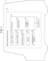
- FIG. 1 is now referred to.
- An own vehicle 1 includes a driving assistance device 10 configured to perform driving assistance of the own vehicle 1.
- the driving assistance performed by the driving assistance device 10 may include self-driving control that, based on, for example, a travel environment around the own vehicle 1, causes the own vehicle 1 to self-drive without involvement of a driver.
- An example of the self-driving control by the driving assistance device 10 may be driving control that causes the own vehicle 1 to self-travel along a preset target travel trajectory in an urban area.
- the driving assistance device 10 includes object sensors 11, vehicle sensors 12, a positioning device 13, a map database 14, a communication device 15, a controller 16, and actuators 17.
- the map database is denoted as "map DB”.
- the object sensors 11 include a plurality of object detection sensors of different types that are mounted on the own vehicle 1 and detect objects around the own vehicle 1, such as a laser radar, a millimeter-wave radar, a camera, and a light detection and ranging or laser imaging detection and ranging (LIDAR).
- object detection sensors of different types that are mounted on the own vehicle 1 and detect objects around the own vehicle 1, such as a laser radar, a millimeter-wave radar, a camera, and a light detection and ranging or laser imaging detection and ranging (LIDAR).
- LIDAR laser imaging detection and ranging
- the vehicle sensors 12 are mounted on the own vehicle 1 and detect various information (vehicle signals) that can be acquired from the own vehicle 1.
- the vehicle sensors 12 include a vehicle speed sensor to detect traveling speed (vehicle speed) of the own vehicle 1, wheel speed sensors to detect rotational speeds of respective tires that the own vehicle 1 includes, a triaxial acceleration sensor (G sensor) to detect acceleration (including deceleration) of the own vehicle 1 in three axial directions, a steering angle sensor to detect a steering angle (including a turning angle), a gyro sensor to detect angular velocity generated in the own vehicle 1, a yaw rate sensor to detect a yaw rate, an accelerator sensor to detect accelerator opening of the own vehicle, and a brake sensor to detect a brake operation amount by the driver.
- G sensor triaxial acceleration sensor
- gyro sensor to detect angular velocity generated in the own vehicle 1
- a yaw rate sensor to detect a yaw rate
- an accelerator sensor to detect accelerator opening of the own vehicle
- the positioning device 13 includes a global navigation satellite system (GNSS) receiver and, by receiving radio waves from a plurality of navigation satellites, measures a current position of the own vehicle 1.
- the GNSS receiver may be, for example, a global positioning system (GPS) receiver or the like.
- the positioning device 13 may be, for example, an inertial navigation device.
- the map database 14 may store high-definition map data (hereinafter, simply referred to as “high-definition map”), which is suitable as a map for self-driving.
- the high-definition map is map data of higher precision than map data for navigation (hereinafter, simply referred to as “navigation map”) and includes information in units of lanes, which is more detailed than information in units of roads.
- the high-definition map includes, as information in units of lanes, information of lane nodes that indicate reference points on a lane reference line (for example, a line at the center of a lane) and information of lane links that indicate forms of lane sections between lane nodes.
- Information of each lane node includes an identification number and position coordinates of the lane node, the number of connected lane links, and identification numbers of connected lane links.
- Information of each lane link includes an identification number of the lane link, the type of the lane, width of the lane, the types of lane boundary lines, a shape of the lane, a shape of a lane marking, and a shape of the lane reference line.
- the high-definition map further includes the types and position coordinates of ground objects, such as a traffic light, a stop line, a road sign, a building, a utility pole, a curb, and a crosswalk, that exist on a lane or in the vicinity of the lane and information of the ground objects, such as identification numbers of lane nodes and identification numbers of lane links that correspond to the position coordinates of the ground objects
- ground objects such as a traffic light, a stop line, a road sign, a building, a utility pole, a curb, and a crosswalk
- the high-definition map includes node information and link information in units of lanes, it is possible to specify a lane in which the own vehicle 1 travels in a travel route.
- the high-definition map has a coordinate system that can represent positions in the extending direction and width direction of each lane.
- the high-definition map has coordinates (for example, longitude, latitude, and altitude) that can represent positions in the three-dimensional space, and lanes and the above-described ground objects may be described as shapes in the three-dimensional space.
- the communication device 15 performs wireless communication with a communication device external to the own vehicle 1.
- a communication method used by the communication device 15 may be, for example, wireless communication via a public mobile telephone network, vehicle-to-vehicle communication, road-to-vehicle communication, or satellite communication.
- the controller 16 is an electronic control unit (ECU) that performs driving assistance control of the own vehicle 1.
- the controller 16 includes a processor 18 and peripheral components, such as a storage device 19.
- the processor 18 may be, for example, a central processing unit (CPU) or a micro-processing unit (MPU).
- the storage device 19 may include a semiconductor storage device, a magnetic storage device, an optical storage device, and the like.
- the storage device 19 may include, registers, a cache memory, and a memory used as a main storage device, such as a read only memory (ROM) and a random access memory (RAM) .
- ROM read only memory
- RAM random access memory
- controller 16 Functions of the controller 16, which will be described below, may be achieved by, for example, the processor 18 executing computer programs stored in the storage device 19.
- controller 16 may be formed by dedicated hardware for executing information processing that will be described below.
- the controller 16 may include a functional logic circuit that is implemented in a general-purpose semiconductor integrated circuit.
- the controller 16 may include a programmable logic device, such as a field-programmable gate array (FPGA), and the like.
- FPGA field-programmable gate array
- the actuators 17 operate a steering wheel, accelerator opening, and a braking device of the own vehicle in accordance with control signals output from the controller 16 and thereby generate vehicle behavior of the own vehicle .
- the actuators 17 include a steering actuator, an accelerator opening actuator, and brake control actuators.
- the steering actuator controls steering direction and the amount of steering of steering of the own vehicle.
- the accelerator opening actuator controls the accelerator opening of the own vehicle.
- the brake control actuators control braking action of the braking devices of the own vehicle 1.
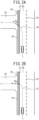
- FIGS. 2A and 2B are now referred to.
- the reference sign 20 indicates a lane in which the own vehicle 1 travels
- the reference signs 21 and 22 indicate demarcation lines indicating boundaries of the lane 20.
- the demarcation line 21 is a lane outside line of the lane 20
- the demarcation line 22 is a lane boundary line.
- the demarcation lines 21 and 22 are examples of a "travelling path boundaries" described in the claims.
- the travelling path boundary is not limited to a demarcation line and may be a ground object, such as a curb and a guardrail, or a road shoulder.
- a passage 23 is connected to the lateral side of the lane 20 so as to face the lane 20, and between the lane 20 and the passage 23, a level difference 24 extends in parallel with the lane 20.
- the passage 23 may be, for example, a passage for entering a facility or a private property.
- the passage 23 does not have to be a distinctively formed passage and may be, for example, a portion of a walkway existing between an entrance to a facility or a private property and the lane 20.
- controller 16 which executes the self-driving control, generates a target travel trajectory 25 that, as illustrated in FIG. 2A , deviates from the lane 21 and enters the passage 23.
- An angle ⁇ s formed by a traveling direction of the own vehicle 1 and an extending direction of the level difference 24 at the time of the own vehicle 1 climbing over the level difference 24 is determined by an angle formed by a straight line parallel with the level difference 24 and the target travel trajectory 25, that is, an angle formed by the intersection of the level difference 24 and the target travel trajectory 25.
- an angle ⁇ s formed by the intersection of the level difference 24 and the target travel trajectory 25 is referred to as a "level-difference climbing-over angle".
- the steered wheels mean wheels steered by a steering mechanism.
- the disturbance becomes larger as the level-difference climbing-over angle ⁇ s is further away from 90 degrees.
- large disturbance is applied to the steered wheels, there is a possibility that an actual steered angle deviates from a target steered angle that is set according to the target travel trajectory 25, the own vehicle 1 departs from the target travel trajectory 25, and the own vehicle 1 is likely to come close to an obstacle around the own vehicle 1.
- the controller 16 when generating a target travel trajectory that climbs over the level difference 24, the controller 16 generates a target travel trajectory in such a way that the level-difference climbing-over angle ⁇ s is larger than a predetermined threshold value Th.
- FIG. 2B an example of a target travel trajectory 27 generated in such a way that the level-difference climbing-over angle ⁇ s is larger than the predetermined threshold value Th is illustrated.
- Generating a target travel trajectory 27 in such a way that the level-difference climbing-over angle ⁇ s is larger than the predetermined threshold value Th enables the own vehicle 1 to climb over the level difference 24 at an angle close to 90 degrees.
- the present invention is not limited thereto.
- the present invention is widely applicable to cases where, in the self-driving control, a target travel trajectory that climbs over a level difference 24 is generated.
- the controller 16 includes an object detection unit 30, an own-vehicle position estimation unit 31, a map acquisition unit 32, a detection integration unit 33, an object tracking unit 34, a position-in-map calculation unit 35, a driving action plan determination unit 36, a travelable region determination unit 37, a target travel trajectory generation unit 38, a level-difference determination unit 39, a level-difference climbing-over angle calculation unit 40, a regeneration determination unit 41, and a vehicle control unit 42.
- the object detection unit 30 detects, based on detection signals from the object sensors 11, positions, attitudes, sizes, speeds, and the like of objects around the own vehicle 1, such as a vehicle, a motorcycle, a pedestrian, and an obstacle.
- the object detection unit 30 outputs detection results representing two-dimensional positions, attitudes, sizes, speeds, and the like of objects in, for example, a zenith view (also referred to as a plan view) in which the own vehicle 1 is viewed from the air.
- the own-vehicle position estimation unit 31 measures, based on a measurement result by the positioning device 13 and odometry using detection results from the vehicle sensors 12, an absolute position of the own vehicle 1, that is, a position of the own vehicle 1 with respect to a predetermined reference point, attitude, and speed of the own vehicle 1.
- the map acquisition unit 32 acquires map information indicating a structure of a road on which the own vehicle 1 is to travel, from the map database 14.
- the map acquisition unit 32 may acquire map information from an external map data server through the communication device 15.
- the detection integration unit 33 integrates a plurality of detection results that the object detection unit 30 respectively acquired from a plurality of object detection sensors and outputs one detection result with respect to each of the respective objects.
- the detection integration unit 33 calculates, from behavior of objects respectively acquired from the object detection sensors, the most reasonable behavior of the objects that minimizes error, in consideration of error characteristics of the respective object detection sensors.
- the detection integration unit 33 comprehensively evaluates detection results acquired by a plurality of types of sensors and acquires a more accurate detection result.
- the object tracking unit 34 tracks objects detected by the object detection unit 30. Specifically, based on the detection results integrated by the detection integration unit 33, the object tracking unit 34 performs verification of identity (association) of objects between different times from behaviors of the objects output at different times and predicts, based on the association, behavior of the objects, such as speed.
- the position-in-map calculation unit 35 estimates a position and an attitude of the own vehicle 1 on the map from the absolute position of the own vehicle 1, which was acquired by the own-vehicle position estimation unit 31, and the map information, which was acquired by the map acquisition unit 32.
- the driving action plan determination unit 36 determines, based on detection results acquired by the detection integration unit 33 and the object tracking unit 34 and the position of the own vehicle 1 identified by the position-in-map calculation unit 35, a schematic driving action of the own vehicle 1 that the driving assistance device 10 is to executes.
- Examples of the driving action that the driving action plan determination unit 36 determines include, for example, stopping of the own vehicle 1, temporary stopping, traveling speed, deceleration, acceleration, course change, right turn, left turn, traveling straight, lane change at a merging section or between a plurality of lanes, lane keeping, overtaking, response to an obstacle, and the like.
- the driving action plan determination unit 36 generates, based on the position and attitude of the own vehicle 1 that the position-in-map calculation unit 35 estimated, the positions and attitudes of objects around the own vehicle 1, and the high-definition map, a route space map that represents existence or nonexistence of a route and an object around the own vehicle 1 and a risk map in which a degree of risk of a traveling field is quantified.
- the driving action plan determination unit 36 generates, based on the route space map and the risk map, a driving action plan of the own vehicle 1.
- the travelable region determination unit 37 determines, based on a driving action plan determined by the driving action plan determination unit 36, motion characteristics of the own vehicle 1, and the route space map, a travelable region where the own vehicle 1 can be caused to travel.
- the target travel trajectory generation unit 38 generates, based on a driving action determined by the driving action plan determination unit 36 and a travelable region determined by the travelable region determination unit 37, candidates of a travel trajectory along which and a speed profile in accordance with which the own vehicle 1 is caused to travel.
- the target travel trajectory generation unit 38 evaluates future risks of the respective candidates, based on the risk map, selects an optimum travel trajectory and speed profile, and sets the selected travel trajectory and speed profile as a target travel trajectory along which and a target speed profile in accordance with which the own vehicle 1 is caused to travel, respectively.
- FIG. 2A is now referred to.
- the target travel trajectory generation unit 38 gradually increases curvature of the target travel trajectory 25 to a maximum curvature and subsequently gradually decreases the curvature of the target travel trajectory 25.
- the target travel trajectory generation unit 38 generates the target travel trajectory 25 formed according to a clothoid curve or a spline curve.
- the target travel trajectory 25 is not limited to a curve that is calculated by a known calculation formula as described above.
- the target travel trajectory 25 is only required to be a curve the curvature of which gradually increases to a maximum curvature and subsequently gradually decreases.
- the target travel trajectory generation unit 38 may determine a curvature change rate of a target travel trajectory with specific parameters. Parameters with which a curvature change rate of a target travel trajectory is determined are hereinafter referred to as "curvature relaxation parameters".
- Curvature relaxation parameters An example of the curvature relaxation parameters is clothoid parameters of a clothoid curve. As the curvature relaxation parameters become larger, a target travel trajectory 25 the curvature of which changes more gently is generated. As the curvature relaxation parameters become smaller, a target travel trajectory 25 the curvature of which changes more steeply is generated.
- the level-difference determination unit 39 acquires level-difference information of the level difference 24, which exists in parallel with the lane 20. For example, the level-difference determination unit 39 may acquire level-difference information, based on an image recognition result of an image captured by a camera. In addition, the level-difference determination unit 39 may acquire level-difference information, based on detection results by the laser radar, the millimeter-wave radar, and the LIDAR.
- the level-difference determination unit 39 may acquire, for example, the position, height, and inclination (an inclination angle of the upper surface of the level difference 24 with respect to the road surface of the lane 20 or the horizontal plane) of the level difference 24 as level-difference information.
- the level-difference determination unit 39 may, by detecting a boundary between a public road and a private property existing on the target travel trajectory 25, based on the map information in the map database 14, acquire level-difference information of the level difference 24 set in place at the boundary between the public road and the private property.
- the level-difference determination unit 39 may acquire, based on a travel history stored when the own vehicle 1 or another vehicle actually traveled, level-difference information of the level difference 24 existing on the target travel trajectory 25.
- the level-difference climbing-over angle calculation unit 40 determines whether or not the target travel trajectory 25 climbs over the level difference 24 (whether or not the target travel trajectory 25 intersects the level difference 24).
- the level-difference climbing-over angle calculation unit 40 calculates a level-difference climbing-over angle ⁇ s when the target travel trajectory 25 climbs over the level difference 24.
- FIG. 4 is now referred to.
- the reference signs 2FL and 2FR indicate the steered wheels of the own vehicle 1
- the reference signs 2RL and 2RR indicate the wheels other than the steered wheels .
- the steered wheels 2FL and 2FR are the left front wheel and the right front wheel, respectively
- the wheels 2RL and 2RR are the left rear wheel and the right rear wheel, respectively.
- the level-difference climbing-over angle calculation unit 40 uses a trajectory that a center position C of an axle 3 of the steered wheels 2FL and 2FR passes as the target travel trajectory 25, calculates a level-difference climbing-over angle ⁇ s formed by a straight line parallel with the level difference 24 and the target travel trajectory 25 (a level-difference climbing-over angle formed by the intersection of the level difference 24 and the target travel trajectory 25).
- FIG. 3 is now referred to.
- the regeneration determination unit 41 determines whether or not to regenerate a target travel trajectory depending on the level-difference climbing-over angle ⁇ s calculated with respect to the target travel trajectory 25 that the target travel trajectory generation unit 38 generated.
- the regeneration determination unit 41 determines to regenerate a target travel trajectory.
- the regeneration determination unit 41 determines not to regenerate a target travel trajectory.
- the regeneration determination unit 41 outputs a determination result to the target travel trajectory generation unit 38.
- the regeneration determination unit 41 may dynamically change the threshold value Th. For example, the regeneration determination unit 41 may set a threshold value Th that changes according to level-difference information of the level difference 24. For example, the regeneration determination unit 41 may set a larger value as the threshold value Th as the level difference 24 is higher. For example, the regeneration determination unit 41 may set a larger value as the threshold value Th as the inclination of the level difference 24 is larger.
- the regeneration determination unit 41 may set a threshold value Th that changes according to an aspect ratio or outer diameter of the tires of the own vehicle 1. For example, the regeneration determination unit 41 may set a larger value as the threshold value Th as the aspect ratio of the tires is lower. For example, the regeneration determination unit 41 may set a larger value as the threshold value Th as the outer diameter of the tires is smaller.
- the regeneration determination unit 41 may acquire obstacle information of obstacles around the own vehicle 1 from the object sensors 11. For example, in a situation illustrated in FIG. 5A , posts 40a and 40b, which are obstacles, exist.
- the regeneration determination unit 41 may set a larger value as the threshold value Th.
- the regeneration determination unit 41 may set a larger value as the threshold value Th as lane width W1 of the lane 23 in which the own vehicle 1, after climbing over the level difference 24, is to travel is narrower.
- Information of the lane width W1 may be acquired from, for example, the map database 14.
- FIG. 3 is now referred to.
- the regeneration determination unit 41 determines to regenerate a target travel trajectory
- the target travel trajectory generation unit 38 regenerates a target travel trajectory.
- the target travel trajectory generation unit 38 regenerates a target travel trajectory in such a way that the level-difference climbing-over angle ⁇ s of the regenerated target travel trajectory increases.
- the target travel trajectory generation unit 38 by reducing the curve relaxation parameters of a target travel trajectory that causes the own vehicle 1 to turn toward the level difference 24, regenerates a target travel trajectory in such a way that the level-difference climbing-over angle ⁇ s increases.
- the target travel trajectory generation unit 38 outputs the target travel trajectory and the target speed profile to the vehicle control unit 42.
- the target travel trajectory generation unit 38 repeats regeneration of a target travel trajectory until the level-difference climbing-over angle ⁇ s becomes larger than the threshold value Th, a target travel trajectory the level-difference climbing-over angle ⁇ s of which is larger than the threshold value Th is generated.
- the target travel trajectory generation unit 38 may set a target speed profile in such a way that target vehicle speed at a point of time when the own vehicle 1 passes the level difference 24 is less than or equal to a predetermined low speed (for example, 10 km/h).
- the target travel trajectory generation unit 38 may dynamically change the target vehicle speed at a point of time when the own vehicle 1 passes the level difference 24.
- the target travel trajectory generation unit 38 may set a target speed profile in such a way that the target vehicle speed at a point of time when the own vehicle 1 passes the level difference 24 changes according to the level-difference information of the level difference 24.
- the target travel trajectory generation unit 38 may set lower the target speed at a point of time when the own vehicle 1 passes the level difference 24 as the level difference 24 is higher.
- the target travel trajectory generation unit 38 may also set lower the target speed at a point of time when the own vehicle 1 passes the level difference 24 as the inclination of the level difference 24 is larger.
- the target travel trajectory generation unit 38 may set a target speed profile in such a way that the target vehicle speed at a point of time when the own vehicle 1 passes the level difference 24 changes according to the aspect ratio of the tires of the own vehicle 1 or the outer diameter of the tires. For example, the target travel trajectory generation unit 38 may set lower the target speed at a point of time when the own vehicle 1 passes the level difference 24 as the aspect ratio is lower. For example, the target travel trajectory generation unit 38 may also set lower the target speed at a point of time when the own vehicle 1 passes the level difference 24 as the outer diameter of the tires is smaller.
- the target travel trajectory generation unit 38 may acquire obstacle information of obstacles around the own vehicle 1 from the object sensors 11.
- the target travel trajectory generation unit 38 may set a target speed profile in such a way that the target speed at a point of time when the own vehicle 1 passes the level difference 24 becomes lower when the obstacles 40a and 40b exist in the vicinity of the target travel trajectory 27 along which the own vehicle 1, after climbing over the level difference 24, is to travel.
- the target travel trajectory generation unit 38 may set a target speed profile in such a way that the target speed at a point of time when the own vehicle 1 passes the level difference 24 becomes lower as the lane width W1 of the lane 23 along which the own vehicle 1, after climbing over the level difference 24, is to travel is narrower.
- the target travel trajectory generation unit 38 may set a target speed profile in such a way that the target vehicle speed at a point of time when the own vehicle 1 passes the level difference 24 changes according to the level-difference climbing-over angle ⁇ s.
- the target travel trajectory generation unit 38 may set lower the target speed at a point of time when the own vehicle 1 passes the level difference 24 as the level-difference climbing-over angle ⁇ s is smaller.
- FIG. 3 is now referred to.
- the vehicle control unit 42 drives the actuators 17 in such a way that the own vehicle 1 travels along the target travel trajectory at a speed in accordance with the target speed profile output from the target travel trajectory generation unit 38.
- step S1 the object detection unit 30, using a plurality of object detection sensors, detects positions, attitudes, sizes, speeds, and the like of objects around the own vehicle 1.
- step S2 the detection integration unit 33 integrates a plurality of detection results acquired respectively from a plurality of object detection sensors and outputs one detection result with respect to each of the respective objects.
- the object tracking unit 34 tracks the respective objects that were detected and integrated and predicts behavior of the objects around the own vehicle 1.
- step S3 the own-vehicle position estimation unit 31 measures, based on a measurement result by the positioning device 13 and odometry using detection results from the vehicle sensors 12, the position, attitude, and speed of the own vehicle 1 with respect to a predetermined reference point.
- step S4 the map acquisition unit 32 acquires map information indicating a structure of a road on which the own vehicle 1 is to travel.
- step S5 the position-in-map calculation unit 35 estimates a position and attitude of the own vehicle 1 on the map from the position of the own vehicle 1 measured in step S3 and the map data acquired in step S4.
- step S6 the driving action plan determination unit 36 determines, based on detection results (behavior of objects around the own vehicle 1) acquired in step S2 and the position of the own vehicle 1 identified in step S5, a driving action of the own vehicle 1 that the driving assistance device 10 is to execute.
- step S7 the travelable region determination unit 37, the target travel trajectory generation unit 38, the level-difference determination unit 39, the level-difference transfer angle calculation unit 40, and the regeneration determination unit 41 execute trajectory generation processing for generating a target travel trajectory of the own vehicle 1.
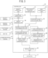
- step S10 the travelable region determination unit 37 determines, in accordance with the driving action plan determined by the driving action plan determination unit 36 and based on motion characteristics of the own vehicle 1 and a route space map, a travelable region in which the own vehicle 1 can be caused to travel.
- the target travel trajectory generation unit 38 generates, based on the driving action determined by the driving action plan determination unit 36 and the travelable region determined by the travelable region determination unit 37, a target travel trajectory and a target speed profile.
- step S11 the level-difference determination unit 39 acquires level-difference information of a level difference 24, which exists in parallel with the lane 20.
- step S12 the level-difference climbing-over angle calculation unit 40 determines whether or not a target travel trajectory 25 climbs over the level difference 24 (whether or not the target travel trajectory 25 intersects the level difference 24).
- the level-difference climbing-over angle calculation unit 40 calculates a level-difference climbing-over angle ⁇ s.
- the regeneration determination unit 41 determines whether or not the level-difference climbing-over angle ⁇ s is less than or equal to a predetermined threshold value Th. When the level-difference climbing-over angle ⁇ s is less than or equal to the predetermined threshold value Th (step S12: Y), the process proceeds to step S13.
- step S13 the target travel trajectory generation unit 38 reduces curve relaxation parameters of the target travel trajectory, which causes the own vehicle 1 to turn toward the level difference 24.
- step S14 the target travel trajectory generation unit 38, using the curve relaxation parameters set in step S13, regenerates a target travel trajectory that climbs over the level difference 24. Subsequently, the process returns to step S12.
- step S12 when, in step S12, the level-difference climbing-over angle ⁇ s is not less than or equal to the predetermined threshold value Th (step S12: N), the target travel trajectory generation unit 38 outputs the target travel trajectory and the target speed profile to the vehicle control unit 42, which finishes the trajectory generation processing, and the process proceeds to step S8 in FIG. 6 .
- step S8 the vehicle control unit 42 controls the own vehicle 1 in such a way that the own vehicle 1 travels in accordance with the target travel trajectory and the speed profile generated in step S7.
- the present invention is not limited thereto.
- the target travel trajectory generation unit 38 may generate the target travel trajectory by appropriately setting curvature relaxation parameters in such a way that the level-difference climbing-over angle ⁇ s is larger than the predetermined threshold value Th.
- the level-difference climbing-over angle calculation unit 40 and the regeneration determination unit 41, illustrated in FIG. 3 may be omitted.
- the target travel trajectory generation unit 38 may determine, based on the driving action plan generated by the driving action plan determination unit 36 and the level-difference information acquired by the level-difference determination unit 39, whether or not to generate a target travel trajectory that climbs over the level difference 24.
- the target travel trajectory generation unit 38 may generate a target travel trajectory the level-difference climbing-over angle ⁇ s of which is larger than the predetermined threshold value Th by appropriately setting smaller curvature relaxation parameters than in the case of generating a target travel trajectory that does not climb over the level difference 24.
- FIG. 8A is now referred to.
- a case is assumed where a target travel trajectory 27 that, from a lane 20, climbs over a level difference 24 and makes a lane change to a branch lane 28 is generated.
- it is necessary to, after making a lane change to the branch lane 28, steer wheels to the opposite side, and, when the level-difference climbing-over angle ⁇ s is brought close to 90 degrees, curvature relaxation parameters exceed an allowable range thereof and the own vehicle 1, after climbing over the level difference 24, becomes unable to travel within the travelling path boundaries of the branch lane 28.
- the level-difference climbing-over angle ⁇ s cannot be brought close to 90 degrees.
- FIG. 8B is now referred to.
- curvature relaxation parameters also exceed the allowable range thereof and the own vehicle 1 becomes unable to travel within the travelling path boundaries of the lane 20 before climbing over the level difference 24.
- the level-difference climbing-over angle ⁇ s also cannot be brought close to 90 degrees.
- a target travel trajectory generation unit 38 of the second embodiment determines whether or not a target travel trajectory can be generated in such a way that the own vehicle 1 travels within the travelling path boundaries and the level-difference transfer angle ⁇ s is larger than the threshold value Th.
- the target travel trajectory generation unit 38 sets a target vehicle speed at a point of time when the own vehicle 1 passes the level difference 24 to a predetermined low speed.
- steps S20 to S23 are the same as the processing in steps S10 to S13 described with reference to FIG. 7 .
- step S24 the target travel trajectory generation unit 38 determines whether or not the curve relaxation parameters reduced in step S23 are within the predetermined allowable range. For example, the target travel trajectory generation unit 38 determines whether or not a target travel trajectory along which the own vehicle 1 travels within the travelling path boundaries can be generated by using the curve relaxation parameters reduced in step S23.
- step S24: N When the curve relaxation parameters are not within the predetermined allowable range (step S24: N), the process proceeds to step S26.
- step S26 the target travel trajectory generation unit 38 sets a target speed profile in such a way that target speed at a point of time when the own vehicle 1 passes the level difference 24 becomes lower.
- the target travel trajectory generation unit 38 sets a target speed profile in such a way that the target speed at a point of time when the own vehicle 1 passes the level difference 24 is a low speed.
- the trajectory generation processing is finished, and the process proceeds to step S8 in FIG. 6 .
- step S24 When the curve relaxation parameters are within the predetermined allowable range (step S24: Y), the process proceeds to step S25. Processing in step S25 is the same as the processing in step S14 described with reference to FIG. 7 . Subsequently, the process returns to step S22.
- An object detection unit 30 detects travelling path boundaries of the lane 20 in which the own vehicle 1 travels.
- the target travel trajectory generation unit 38 sets the target vehicle speed at a point of time when the own vehicle 1 passes the level difference 24 to the low speed.
Landscapes
- Engineering & Computer Science (AREA)
- Automation & Control Theory (AREA)
- Transportation (AREA)
- Mechanical Engineering (AREA)
- Human Computer Interaction (AREA)
- Physics & Mathematics (AREA)
- Mathematical Physics (AREA)
- Chemical & Material Sciences (AREA)
- Combustion & Propulsion (AREA)
- Traffic Control Systems (AREA)
- Control Of Driving Devices And Active Controlling Of Vehicle (AREA)
Applications Claiming Priority (1)
| Application Number | Priority Date | Filing Date | Title |
|---|---|---|---|
| PCT/IB2020/000325 WO2021205191A1 (ja) | 2020-04-06 | 2020-04-06 | 運転支援方法及び運転支援装置 |
Publications (3)
| Publication Number | Publication Date |
|---|---|
| EP4134286A1 true EP4134286A1 (de) | 2023-02-15 |
| EP4134286A4 EP4134286A4 (de) | 2023-05-31 |
| EP4134286B1 EP4134286B1 (de) | 2024-02-28 |
Family
ID=78024061
Family Applications (1)
| Application Number | Title | Priority Date | Filing Date |
|---|---|---|---|
| EP20930629.9A Active EP4134286B1 (de) | 2020-04-06 | 2020-04-06 | Fahrassistenzverfahren und fahrassistenzvorrichtung |
Country Status (5)
| Country | Link |
|---|---|
| US (1) | US12091047B2 (de) |
| EP (1) | EP4134286B1 (de) |
| JP (1) | JP7346722B2 (de) |
| CN (1) | CN115397709A (de) |
| WO (1) | WO2021205191A1 (de) |
Families Citing this family (1)
| Publication number | Priority date | Publication date | Assignee | Title |
|---|---|---|---|---|
| US20220340168A1 (en) * | 2019-06-14 | 2022-10-27 | Nissan Motor Co., Ltd. | Travel Assistance Method and Travel Assistance Device |
Family Cites Families (13)
| Publication number | Priority date | Publication date | Assignee | Title |
|---|---|---|---|---|
| JP2010241320A (ja) * | 2009-04-08 | 2010-10-28 | Toyota Motor Corp | 車両の操舵装置 |
| JP2014101101A (ja) * | 2012-11-22 | 2014-06-05 | Denso Corp | 駐車支援装置 |
| US9886636B2 (en) * | 2013-05-23 | 2018-02-06 | GM Global Technology Operations LLC | Enhanced top-down view generation in a front curb viewing system |
| JP6096157B2 (ja) | 2014-09-12 | 2017-03-15 | アイシン精機株式会社 | 駐車支援装置 |
| JP6670083B2 (ja) | 2015-12-01 | 2020-03-18 | パイオニア株式会社 | 推定装置 |
| WO2018193577A1 (ja) | 2017-04-20 | 2018-10-25 | 三菱電機株式会社 | 駐車支援制御装置および駐車支援制御方法 |
| US10569651B2 (en) * | 2017-05-15 | 2020-02-25 | Baidu Usa Llc | Speed control and steering control assistant based on pitch status and roll status of autonomous driving vehicle |
| DE102017217441B4 (de) * | 2017-09-29 | 2019-06-13 | Volkswagen Ag | Verfahren zum Durchführen eines Bordsteinparkens eines Kraftfahrzeugs, Vorrichtung und Kraftfahrzeug |
| JP6554568B2 (ja) * | 2018-01-24 | 2019-07-31 | 本田技研工業株式会社 | 車両制御装置 |
| JP2019144030A (ja) | 2018-02-19 | 2019-08-29 | 株式会社ゼンリン | 走行支援装置及び地図データのデータ構造 |
| JP2020040515A (ja) | 2018-09-11 | 2020-03-19 | 本田技研工業株式会社 | 車両走行制御装置 |
| US11834058B2 (en) * | 2019-01-04 | 2023-12-05 | Toyota Research Institute, Inc. | Systems and methods for controlling a vehicle based on vehicle states and constraints of the vehicle |
| DE102019003430B3 (de) * | 2019-05-15 | 2020-06-04 | Daimler Ag | Verfahren zur Durchführung eines automatisierten oder autonomen Fahrbetriebs eines Fahrzeugs |
-
2020
- 2020-04-06 CN CN202080099456.1A patent/CN115397709A/zh active Pending
- 2020-04-06 JP JP2022514036A patent/JP7346722B2/ja active Active
- 2020-04-06 US US17/916,961 patent/US12091047B2/en active Active
- 2020-04-06 EP EP20930629.9A patent/EP4134286B1/de active Active
- 2020-04-06 WO PCT/IB2020/000325 patent/WO2021205191A1/ja unknown
Also Published As
| Publication number | Publication date |
|---|---|
| US20230166763A1 (en) | 2023-06-01 |
| WO2021205191A1 (ja) | 2021-10-14 |
| JPWO2021205191A1 (de) | 2021-10-14 |
| EP4134286A4 (de) | 2023-05-31 |
| EP4134286B1 (de) | 2024-02-28 |
| US12091047B2 (en) | 2024-09-17 |
| CN115397709A (zh) | 2022-11-25 |
| JP7346722B2 (ja) | 2023-09-19 |
Similar Documents
| Publication | Publication Date | Title |
|---|---|---|
| US11313976B2 (en) | Host vehicle position estimation device | |
| US11987245B2 (en) | Method for controlling vehicle and vehicle control device | |
| US11761787B2 (en) | Map information correction method, driving assistance method, and map information correction device | |
| US12128888B2 (en) | Behavior prediction method and behavior prediction device for mobile unit, and vehicle | |
| EP4134288B1 (de) | Verfahren zur schätzung des fahrzeugverhaltens, fahrzeugsteuerungsverfahren und vorrichtung zur schätzung des fahrzeugverhaltens | |
| US20200139981A1 (en) | Inter-Vehicle Sensor Validation using Senso-Fusion Network | |
| CN118235180A (zh) | 预测可行驶车道的方法和装置 | |
| US12033403B2 (en) | Vehicle control device, vehicle control method, and storage medium | |
| EP4134286B1 (de) | Fahrassistenzverfahren und fahrassistenzvorrichtung | |
| US20230139551A1 (en) | Lane bias maneuver for autonomous vehicles to avoid an intruding vehicle | |
| US20220306150A1 (en) | Control device, control method, and storage medium | |
| RU2803579C1 (ru) | Способ содействия при вождении и устройство содействия при вождении | |
| US20250026346A1 (en) | Vehicle Control Method and Vehicle Control Device | |
| CN115701400A (zh) | 一种无人驾驶框架车系统 | |
| EP4442526A1 (de) | Fahrzeugsteuerungsverfahren und fahrzeugsteuerungsvorrichtung | |
| US12202482B1 (en) | Vehicle control method and vehicle control device | |
| KR102581080B1 (ko) | 정밀지도 기반으로 자율주행자동차의 종방향 주행을 제어하는 방법 및 이를 이용한 자율주행 제어 장치 | |
| US20230001918A1 (en) | Vehicle control system | |
| EP4397553A1 (de) | Fahrzeugsteuerungsverfahren und fahrzeugsteuerungsvorrichtung | |
| JP7458797B2 (ja) | 走行支援方法及び走行支援装置 | |
| EP4443409A1 (de) | Einparkassistenzverfahren und einparkassistenzvorrichtung | |
| RU2788556C1 (ru) | Способ управления транспортным средством и устройство управления транспортным средством | |
| WO2024154231A1 (ja) | 環境認識装置、走行可能エリア決定方法及び電子制御装置 | |
| RU2803578C1 (ru) | Способ исправления картографической информации, способ содействия вождению и устройство исправления картографической информации | |
| WO2021074659A1 (ja) | 運転支援方法及び運転支援装置 |
Legal Events
| Date | Code | Title | Description |
|---|---|---|---|
| STAA | Information on the status of an ep patent application or granted ep patent |
Free format text: STATUS: THE INTERNATIONAL PUBLICATION HAS BEEN MADE |
|
| PUAI | Public reference made under article 153(3) epc to a published international application that has entered the european phase |
Free format text: ORIGINAL CODE: 0009012 |
|
| STAA | Information on the status of an ep patent application or granted ep patent |
Free format text: STATUS: REQUEST FOR EXAMINATION WAS MADE |
|
| 17P | Request for examination filed |
Effective date: 20221103 |
|
| AK | Designated contracting states |
Kind code of ref document: A1 Designated state(s): AL AT BE BG CH CY CZ DE DK EE ES FI FR GB GR HR HU IE IS IT LI LT LU LV MC MK MT NL NO PL PT RO RS SE SI SK SM TR |
|
| A4 | Supplementary search report drawn up and despatched |
Effective date: 20230428 |
|
| RIC1 | Information provided on ipc code assigned before grant |
Ipc: B60W 60/00 20200101ALI20230421BHEP Ipc: B60W 30/18 20120101ALI20230421BHEP Ipc: B60W 10/20 20060101ALI20230421BHEP Ipc: B60W 30/10 20060101AFI20230421BHEP |
|
| DAV | Request for validation of the european patent (deleted) | ||
| DAX | Request for extension of the european patent (deleted) | ||
| RIC1 | Information provided on ipc code assigned before grant |
Ipc: B60W 60/00 20200101ALI20231019BHEP Ipc: B60W 30/18 20120101ALI20231019BHEP Ipc: B60W 10/20 20060101ALI20231019BHEP Ipc: B60W 30/10 20060101AFI20231019BHEP |
|
| GRAP | Despatch of communication of intention to grant a patent |
Free format text: ORIGINAL CODE: EPIDOSNIGR1 |
|
| STAA | Information on the status of an ep patent application or granted ep patent |
Free format text: STATUS: GRANT OF PATENT IS INTENDED |
|
| INTG | Intention to grant announced |
Effective date: 20231124 |
|
| GRAS | Grant fee paid |
Free format text: ORIGINAL CODE: EPIDOSNIGR3 |
|
| GRAA | (expected) grant |
Free format text: ORIGINAL CODE: 0009210 |
|
| STAA | Information on the status of an ep patent application or granted ep patent |
Free format text: STATUS: THE PATENT HAS BEEN GRANTED |
|
| AK | Designated contracting states |
Kind code of ref document: B1 Designated state(s): AL AT BE BG CH CY CZ DE DK EE ES FI FR GB GR HR HU IE IS IT LI LT LU LV MC MK MT NL NO PL PT RO RS SE SI SK SM TR |
|
| REG | Reference to a national code |
Ref country code: GB Ref legal event code: FG4D |
|
| REG | Reference to a national code |
Ref country code: CH Ref legal event code: EP |
|
| REG | Reference to a national code |
Ref country code: DE Ref legal event code: R096 Ref document number: 602020026619 Country of ref document: DE |
|
| REG | Reference to a national code |
Ref country code: IE Ref legal event code: FG4D |
|
| REG | Reference to a national code |
Ref country code: LT Ref legal event code: MG9D |
|
| PG25 | Lapsed in a contracting state [announced via postgrant information from national office to epo] |
Ref country code: IS Free format text: LAPSE BECAUSE OF FAILURE TO SUBMIT A TRANSLATION OF THE DESCRIPTION OR TO PAY THE FEE WITHIN THE PRESCRIBED TIME-LIMIT Effective date: 20240628 |
|
| REG | Reference to a national code |
Ref country code: NL Ref legal event code: MP Effective date: 20240228 |
|
| PGFP | Annual fee paid to national office [announced via postgrant information from national office to epo] |
Ref country code: GB Payment date: 20240423 Year of fee payment: 5 |
|
| PG25 | Lapsed in a contracting state [announced via postgrant information from national office to epo] |
Ref country code: LT Free format text: LAPSE BECAUSE OF FAILURE TO SUBMIT A TRANSLATION OF THE DESCRIPTION OR TO PAY THE FEE WITHIN THE PRESCRIBED TIME-LIMIT Effective date: 20240228 |
|
| PGFP | Annual fee paid to national office [announced via postgrant information from national office to epo] |
Ref country code: DE Payment date: 20240425 Year of fee payment: 5 |
|
| PG25 | Lapsed in a contracting state [announced via postgrant information from national office to epo] |
Ref country code: GR Free format text: LAPSE BECAUSE OF FAILURE TO SUBMIT A TRANSLATION OF THE DESCRIPTION OR TO PAY THE FEE WITHIN THE PRESCRIBED TIME-LIMIT Effective date: 20240529 |
|
| PG25 | Lapsed in a contracting state [announced via postgrant information from national office to epo] |
Ref country code: HR Free format text: LAPSE BECAUSE OF FAILURE TO SUBMIT A TRANSLATION OF THE DESCRIPTION OR TO PAY THE FEE WITHIN THE PRESCRIBED TIME-LIMIT Effective date: 20240228 Ref country code: RS Free format text: LAPSE BECAUSE OF FAILURE TO SUBMIT A TRANSLATION OF THE DESCRIPTION OR TO PAY THE FEE WITHIN THE PRESCRIBED TIME-LIMIT Effective date: 20240528 Ref country code: NL Free format text: LAPSE BECAUSE OF FAILURE TO SUBMIT A TRANSLATION OF THE DESCRIPTION OR TO PAY THE FEE WITHIN THE PRESCRIBED TIME-LIMIT Effective date: 20240228 |
|
| PG25 | Lapsed in a contracting state [announced via postgrant information from national office to epo] |
Ref country code: ES Free format text: LAPSE BECAUSE OF FAILURE TO SUBMIT A TRANSLATION OF THE DESCRIPTION OR TO PAY THE FEE WITHIN THE PRESCRIBED TIME-LIMIT Effective date: 20240228 |
|
| PG25 | Lapsed in a contracting state [announced via postgrant information from national office to epo] |
Ref country code: RS Free format text: LAPSE BECAUSE OF FAILURE TO SUBMIT A TRANSLATION OF THE DESCRIPTION OR TO PAY THE FEE WITHIN THE PRESCRIBED TIME-LIMIT Effective date: 20240528 Ref country code: NO Free format text: LAPSE BECAUSE OF FAILURE TO SUBMIT A TRANSLATION OF THE DESCRIPTION OR TO PAY THE FEE WITHIN THE PRESCRIBED TIME-LIMIT Effective date: 20240528 Ref country code: NL Free format text: LAPSE BECAUSE OF FAILURE TO SUBMIT A TRANSLATION OF THE DESCRIPTION OR TO PAY THE FEE WITHIN THE PRESCRIBED TIME-LIMIT Effective date: 20240228 Ref country code: LT Free format text: LAPSE BECAUSE OF FAILURE TO SUBMIT A TRANSLATION OF THE DESCRIPTION OR TO PAY THE FEE WITHIN THE PRESCRIBED TIME-LIMIT Effective date: 20240228 Ref country code: IS Free format text: LAPSE BECAUSE OF FAILURE TO SUBMIT A TRANSLATION OF THE DESCRIPTION OR TO PAY THE FEE WITHIN THE PRESCRIBED TIME-LIMIT Effective date: 20240628 Ref country code: HR Free format text: LAPSE BECAUSE OF FAILURE TO SUBMIT A TRANSLATION OF THE DESCRIPTION OR TO PAY THE FEE WITHIN THE PRESCRIBED TIME-LIMIT Effective date: 20240228 Ref country code: GR Free format text: LAPSE BECAUSE OF FAILURE TO SUBMIT A TRANSLATION OF THE DESCRIPTION OR TO PAY THE FEE WITHIN THE PRESCRIBED TIME-LIMIT Effective date: 20240529 Ref country code: FI Free format text: LAPSE BECAUSE OF FAILURE TO SUBMIT A TRANSLATION OF THE DESCRIPTION OR TO PAY THE FEE WITHIN THE PRESCRIBED TIME-LIMIT Effective date: 20240228 Ref country code: ES Free format text: LAPSE BECAUSE OF FAILURE TO SUBMIT A TRANSLATION OF THE DESCRIPTION OR TO PAY THE FEE WITHIN THE PRESCRIBED TIME-LIMIT Effective date: 20240228 Ref country code: BG Free format text: LAPSE BECAUSE OF FAILURE TO SUBMIT A TRANSLATION OF THE DESCRIPTION OR TO PAY THE FEE WITHIN THE PRESCRIBED TIME-LIMIT Effective date: 20240228 |
|
| PGFP | Annual fee paid to national office [announced via postgrant information from national office to epo] |
Ref country code: FR Payment date: 20240423 Year of fee payment: 5 |
|
| PG25 | Lapsed in a contracting state [announced via postgrant information from national office to epo] |
Ref country code: PT Free format text: LAPSE BECAUSE OF FAILURE TO SUBMIT A TRANSLATION OF THE DESCRIPTION OR TO PAY THE FEE WITHIN THE PRESCRIBED TIME-LIMIT Effective date: 20240628 Ref country code: PL Free format text: LAPSE BECAUSE OF FAILURE TO SUBMIT A TRANSLATION OF THE DESCRIPTION OR TO PAY THE FEE WITHIN THE PRESCRIBED TIME-LIMIT Effective date: 20240228 |
|
| REG | Reference to a national code |
Ref country code: AT Ref legal event code: MK05 Ref document number: 1660973 Country of ref document: AT Kind code of ref document: T Effective date: 20240228 |
|
| PG25 | Lapsed in a contracting state [announced via postgrant information from national office to epo] |
Ref country code: SE Free format text: LAPSE BECAUSE OF FAILURE TO SUBMIT A TRANSLATION OF THE DESCRIPTION OR TO PAY THE FEE WITHIN THE PRESCRIBED TIME-LIMIT Effective date: 20240228 Ref country code: PT Free format text: LAPSE BECAUSE OF FAILURE TO SUBMIT A TRANSLATION OF THE DESCRIPTION OR TO PAY THE FEE WITHIN THE PRESCRIBED TIME-LIMIT Effective date: 20240628 Ref country code: PL Free format text: LAPSE BECAUSE OF FAILURE TO SUBMIT A TRANSLATION OF THE DESCRIPTION OR TO PAY THE FEE WITHIN THE PRESCRIBED TIME-LIMIT Effective date: 20240228 Ref country code: LV Free format text: LAPSE BECAUSE OF FAILURE TO SUBMIT A TRANSLATION OF THE DESCRIPTION OR TO PAY THE FEE WITHIN THE PRESCRIBED TIME-LIMIT Effective date: 20240228 |
|
| PG25 | Lapsed in a contracting state [announced via postgrant information from national office to epo] |
Ref country code: DK Free format text: LAPSE BECAUSE OF FAILURE TO SUBMIT A TRANSLATION OF THE DESCRIPTION OR TO PAY THE FEE WITHIN THE PRESCRIBED TIME-LIMIT Effective date: 20240228 |
|
| PG25 | Lapsed in a contracting state [announced via postgrant information from national office to epo] |
Ref country code: SM Free format text: LAPSE BECAUSE OF FAILURE TO SUBMIT A TRANSLATION OF THE DESCRIPTION OR TO PAY THE FEE WITHIN THE PRESCRIBED TIME-LIMIT Effective date: 20240228 |
|
| PG25 | Lapsed in a contracting state [announced via postgrant information from national office to epo] |
Ref country code: CZ Free format text: LAPSE BECAUSE OF FAILURE TO SUBMIT A TRANSLATION OF THE DESCRIPTION OR TO PAY THE FEE WITHIN THE PRESCRIBED TIME-LIMIT Effective date: 20240228 Ref country code: EE Free format text: LAPSE BECAUSE OF FAILURE TO SUBMIT A TRANSLATION OF THE DESCRIPTION OR TO PAY THE FEE WITHIN THE PRESCRIBED TIME-LIMIT Effective date: 20240228 |
|
| PG25 | Lapsed in a contracting state [announced via postgrant information from national office to epo] |
Ref country code: AT Free format text: LAPSE BECAUSE OF FAILURE TO SUBMIT A TRANSLATION OF THE DESCRIPTION OR TO PAY THE FEE WITHIN THE PRESCRIBED TIME-LIMIT Effective date: 20240228 |
|
| PG25 | Lapsed in a contracting state [announced via postgrant information from national office to epo] |
Ref country code: SK Free format text: LAPSE BECAUSE OF FAILURE TO SUBMIT A TRANSLATION OF THE DESCRIPTION OR TO PAY THE FEE WITHIN THE PRESCRIBED TIME-LIMIT Effective date: 20240228 |
|
| PG25 | Lapsed in a contracting state [announced via postgrant information from national office to epo] |
Ref country code: SM Free format text: LAPSE BECAUSE OF FAILURE TO SUBMIT A TRANSLATION OF THE DESCRIPTION OR TO PAY THE FEE WITHIN THE PRESCRIBED TIME-LIMIT Effective date: 20240228 Ref country code: SK Free format text: LAPSE BECAUSE OF FAILURE TO SUBMIT A TRANSLATION OF THE DESCRIPTION OR TO PAY THE FEE WITHIN THE PRESCRIBED TIME-LIMIT Effective date: 20240228 Ref country code: RO Free format text: LAPSE BECAUSE OF FAILURE TO SUBMIT A TRANSLATION OF THE DESCRIPTION OR TO PAY THE FEE WITHIN THE PRESCRIBED TIME-LIMIT Effective date: 20240228 Ref country code: EE Free format text: LAPSE BECAUSE OF FAILURE TO SUBMIT A TRANSLATION OF THE DESCRIPTION OR TO PAY THE FEE WITHIN THE PRESCRIBED TIME-LIMIT Effective date: 20240228 Ref country code: DK Free format text: LAPSE BECAUSE OF FAILURE TO SUBMIT A TRANSLATION OF THE DESCRIPTION OR TO PAY THE FEE WITHIN THE PRESCRIBED TIME-LIMIT Effective date: 20240228 Ref country code: CZ Free format text: LAPSE BECAUSE OF FAILURE TO SUBMIT A TRANSLATION OF THE DESCRIPTION OR TO PAY THE FEE WITHIN THE PRESCRIBED TIME-LIMIT Effective date: 20240228 Ref country code: AT Free format text: LAPSE BECAUSE OF FAILURE TO SUBMIT A TRANSLATION OF THE DESCRIPTION OR TO PAY THE FEE WITHIN THE PRESCRIBED TIME-LIMIT Effective date: 20240228 |