EP4132833B1 - Drehgestell für ein schienenfahrzeug mit wankstütze - Google Patents
Drehgestell für ein schienenfahrzeug mit wankstütze Download PDFInfo
- Publication number
- EP4132833B1 EP4132833B1 EP21716655.2A EP21716655A EP4132833B1 EP 4132833 B1 EP4132833 B1 EP 4132833B1 EP 21716655 A EP21716655 A EP 21716655A EP 4132833 B1 EP4132833 B1 EP 4132833B1
- Authority
- EP
- European Patent Office
- Prior art keywords
- torsion
- bogie
- torsion spring
- spring system
- roll stabilizer
- Prior art date
- Legal status (The legal status is an assumption and is not a legal conclusion. Google has not performed a legal analysis and makes no representation as to the accuracy of the status listed.)
- Active
Links
Images




Classifications
-
- B—PERFORMING OPERATIONS; TRANSPORTING
- B61—RAILWAYS
- B61F—RAIL VEHICLE SUSPENSIONS, e.g. UNDERFRAMES, BOGIES OR ARRANGEMENTS OF WHEEL AXLES; RAIL VEHICLES FOR USE ON TRACKS OF DIFFERENT WIDTH; PREVENTING DERAILING OF RAIL VEHICLES; WHEEL GUARDS, OBSTRUCTION REMOVERS OR THE LIKE FOR RAIL VEHICLES
- B61F5/00—Constructional details of bogies; Connections between bogies and vehicle underframes; Arrangements or devices for adjusting or allowing self-adjustment of wheel axles or bogies when rounding curves
- B61F5/02—Arrangements permitting limited transverse relative movements between vehicle underframe or bolster and bogie; Connections between underframes and bogies
- B61F5/14—Side bearings
-
- B—PERFORMING OPERATIONS; TRANSPORTING
- B61—RAILWAYS
- B61F—RAIL VEHICLE SUSPENSIONS, e.g. UNDERFRAMES, BOGIES OR ARRANGEMENTS OF WHEEL AXLES; RAIL VEHICLES FOR USE ON TRACKS OF DIFFERENT WIDTH; PREVENTING DERAILING OF RAIL VEHICLES; WHEEL GUARDS, OBSTRUCTION REMOVERS OR THE LIKE FOR RAIL VEHICLES
- B61F5/00—Constructional details of bogies; Connections between bogies and vehicle underframes; Arrangements or devices for adjusting or allowing self-adjustment of wheel axles or bogies when rounding curves
- B61F5/02—Arrangements permitting limited transverse relative movements between vehicle underframe or bolster and bogie; Connections between underframes and bogies
- B61F5/22—Guiding of the vehicle underframes with respect to the bogies
- B61F5/24—Means for damping or minimising the canting, skewing, pitching, or plunging movements of the underframes
-
- B—PERFORMING OPERATIONS; TRANSPORTING
- B61—RAILWAYS
- B61F—RAIL VEHICLE SUSPENSIONS, e.g. UNDERFRAMES, BOGIES OR ARRANGEMENTS OF WHEEL AXLES; RAIL VEHICLES FOR USE ON TRACKS OF DIFFERENT WIDTH; PREVENTING DERAILING OF RAIL VEHICLES; WHEEL GUARDS, OBSTRUCTION REMOVERS OR THE LIKE FOR RAIL VEHICLES
- B61F5/00—Constructional details of bogies; Connections between bogies and vehicle underframes; Arrangements or devices for adjusting or allowing self-adjustment of wheel axles or bogies when rounding curves
- B61F5/26—Mounting or securing axle-boxes in vehicle or bogie underframes
- B61F5/30—Axle-boxes mounted for movement under spring control in vehicle or bogie underframes
- B61F5/301—Axle-boxes mounted for movement under spring control in vehicle or bogie underframes incorporating metal springs
- B61F5/304—Torsion-bar springs
-
- B—PERFORMING OPERATIONS; TRANSPORTING
- B61—RAILWAYS
- B61F—RAIL VEHICLE SUSPENSIONS, e.g. UNDERFRAMES, BOGIES OR ARRANGEMENTS OF WHEEL AXLES; RAIL VEHICLES FOR USE ON TRACKS OF DIFFERENT WIDTH; PREVENTING DERAILING OF RAIL VEHICLES; WHEEL GUARDS, OBSTRUCTION REMOVERS OR THE LIKE FOR RAIL VEHICLES
- B61F5/00—Constructional details of bogies; Connections between bogies and vehicle underframes; Arrangements or devices for adjusting or allowing self-adjustment of wheel axles or bogies when rounding curves
- B61F5/50—Other details
- B61F5/52—Bogie frames
Definitions
- the invention relates to a bogie according to the preamble of claim 1.
- bogies in fiber composite construction are known from the state of the art, in which the primary suspension is provided by the bogie frame, as in the DE 29 52 182 A1 described, or is realized by leaf springs made of a fiber-reinforced plastic (FRP), such as from the US 2012/0279416 A1 known.
- FRP fiber-reinforced plastic
- torsion bars also known as torsion springs, torsion bars or torsion springs
- the torsional stiffness of a torsion spring made of fiber composite material includes the elastic modulus E in the longitudinal direction of the fibers and not, as is the case with metallic springs, for example, the generally smaller shear modulus G.
- bogies in which the primary suspension is implemented by means of torsion bars have high lightweight construction potential and installation space for installations.
- a bogie with torsion bar primary suspension in which the wheel axles are attached to the frame by vertically oscillating links, with each link being attached to the outer end of a torsion bar arranged transversely to the direction of travel, is known, for example, from the DE 735 080 A or from the DE 10 2016 123 784 A1
- a similar design is known in the DE 838 897 A described, whereby the control arms are height-adjustable via an adjustable anchoring of the torsion bars in the center of the bogie.
- torsion bars are also used to provide transverse stabilization of the car body, i.e. to reduce or stabilize the rolling motion of the car body around its longitudinal axis.
- the DE 28 41 769 A1 shows a torsion bar that acts as a transverse stabilizer and connects the rockers arranged on opposite sides of the vehicle.
- the upper bearing of a coil spring for cushioning the car body is attached to each rocker, which is attached to the bogie frame via a rocker bracket, in a movably manner.
- a roll support in the form of a torsion bar arranged transversely to the direction of travel with cranks at the ends is often used, which are usually pivotably mounted on the car body, with the connection between the cranks and the car body being made via pendulum supports.
- the CN 205 059 624 U shows an anti-roll torsion bar for rail transport, the anti-roll torsion bar comprising a first torsion bar assembly and a second torsion bar assembly.
- the first torsion bar assembly comprises a first torsion bar axis, a first torsion arm attached to the first torsion bar axis, and a first vertical connecting bar attached to the first torsion arm.
- the second torsion bar assembly includes a second torsion bar axle, a second torsion arm attached to the second torsion bar axle, and a second vertical connecting bar attached to the second torsion arm.
- the second torsion bar axle is attached to and coaxial with the first torsion bar axle via a torsion bar shaft coupling, the first torsion bar axle extending from both ends of the second torsion bar axle, and the first torsion arm is provided on the outside of the second torsion arm.
- the first torsion bar axle is attached to the second torsion bar axle with a mounting assembly to mount the anti-roll torsion bar for rail transportation to a bogie.
- a rail vehicle can have stronger anti-roll rigidity with a composite anti-roll torsion bar system as well as stronger anti-roll sensitivity to meet safety requirements.
- the object of the invention is to provide a bogie with anti-roll support which has a particularly large amount of installation space for additional installations.
- the bogie according to the invention has at least two wheel sets, each wheel set comprising two wheels connected to an axle.
- the wheel set is mounted in axle bearings which are connected to the frame in an articulated manner via axle guides, so that the axle guides form an H-shape with the axle bearings and the frame.
- the frame has at least two torsion spring systems arranged parallel to the axles of the wheel sets, which are firmly connected to the frame in some areas.
- the torsion spring systems have spring lever arms at the end, so that the end area of the spring lever arm not connected to the torsion spring system acts on the axle bearing.
- the primary suspension is therefore at least partially taken over by the at least two torsion spring systems.
- the bogie according to the invention also has at least one anti-roll support which has a torsion bar which is arranged in a torsionally movable manner in the inner volume of at least one of the torsion spring systems.
- the torsion bar of the anti-roll support is therefore, like the torsion spring system, arranged transversely to the direction of travel of the bogie, i.e. the central axis of the torsion bar of the anti-roll support is also arranged at least approximately parallel to the axes of the wheel sets
- Each of the at least two torsion spring systems has at least one torsion bar, which is designed as a hollow body.
- a torsion spring system can have exactly one torsion bar, which is mounted firmly in the frame in the region of half its height and whose two ends each have a spring lever.
- a torsion spring system can also have two torsion bars arranged one after the other in the axial direction. The ends of the torsion bars facing each other are then mounted firmly on the frame. The other ends of the two torsion bars each have a spring lever.
- the bogie according to the invention advantageously has a large installation space for installations.
- the torsion bar of the anti-roll bar is hinged to the torsion spring system, which is at least part of the primary suspension of the rail vehicle.
- the torsion spring systems can be arranged in corresponding recesses within the frame to save space.
- the end regions of the torsion bar of the anti-roll support protrude beyond the torsion spring system on both sides.
- At least one pendulum support arrangement is arranged on each of the two end regions of the torsion bar of the anti-roll support, the end of which is not connected to the torsion bar and is hinged to the car body of the rail vehicle, so that the two pendulum support arrangements are mechanically and energy-transmittingly hinged to opposite sides of the car body.
- the torsion bar of the anti-roll support is at least indirectly connected to the torsion spring system by force-fitting or force-fitting and form-fitting means connected, for example via an end-side press connection or an end-side toothing between the torsion bar of the anti-roll support and the torsion spring system or between the torsion bar of the anti-roll support and a transmission element connected to the torsion spring system.
- This design offers a lot of installation space and requires very few components and no additional attachments to the car body.
- the geometry and material of the torsion bars of the torsion spring system and the anti-roll support can be adapted in a defined manner to the expected loads.
- the torsion bars can, for example, have a round, oval or polygonal cross-sectional outer contour, which can be constant or variable over the length, i.e. along the central axis, of the torsion bars.
- the torsion bar of the anti-roll support is preferably designed as a hollow body, just like the at least one torsion bar of a torsion spring system.
- the wall thickness of the torsion bars designed as hollow bodies can be constant or variable over the length. The wall thickness is preferably greater in areas of the torsion bars that are subject to particularly mechanical stress, for example in the end areas, than in other areas.
- the torsion bar of the anti-roll support consists at least predominantly of a fiber-reinforced plastic.
- at least one torsion bar of the torsion spring system of the bogie is also preferably made at least predominantly of a fiber-reinforced plastic.
- at least the frame and/or the spring lever arms of the bogie are also at least predominantly made of a fiber-reinforced plastic.
- “At least predominantly" means that the components mentioned can also be designed as a hybrid structure, e.g. by using a metallic insert to introduce force, with the main function of the torsion being carried out by the fiber composite component.
- All fibres in particular carbon, glass or aramid fibres or a combination of the above, which can withstand the loads occurring during operation of the bogie are suitable as fibres.
- All resins, particularly synthetic resins, are suitable that can withstand the loads that occur during operation of the bogie. These can be easily determined by a person skilled in the art with knowledge of the inventive concept.
- the solution according to the invention is based on the fact that the torsion bar of at least one anti-roll support of the bogie arranged transversely to the direction of travel of the bogie is arranged to be torsionally movable approximately concentrically within the at least one torsion bar of a torsion spring system which is designed for at least partial primary suspension of the bogie.
- the invention is explained below by means of exemplary embodiments based on figures, without being restricted to these. In the figures, for the sake of better clarity, where identical components occur multiple times, only one is provided with a reference symbol.
- Fig. 1 shows a plan view of an embodiment of a bogie according to the invention for a rail vehicle.
- the bogie 1, 1*, 1** has two wheel sets 2, each mounted in two axle bearings 21, with two wheels 202 connected by an axle 201.
- Each axle bearing 21 is articulated to the frame 3 via an axle guide 22.
- the bogie 1, 1*, 1** has one torsion spring system per wheel set 2, which is arranged parallel to the axle 201 of the corresponding wheel set 2 in the frame 3 and is therefore not visible in the illustration shown.
- Spring lever arms 4 are arranged at the ends of the torsion spring system, with one end region of each spring lever arm 4 being supported by a damping body, e.g. B. a rubber pad 41, acts on an axle bearing 21.
- a damping body e.g. B. a rubber pad 41
- a pivot pin 5 is arranged on the frame 3; an elastic connection between the car body and the bogie 1, 1*, 1** is established by air springs 6 arranged on the frame 3 for secondary suspension.
- the bogie 1, 1*, 1** advantageously has a particularly large amount of installation space for other operationally relevant components, such as the motors 7, the gearboxes 8 and the brakes 9.
- the frame 3, the spring lever arms 4, the torsion spring systems and the torsion bar of the anti-roll support can be made at least predominantly from a FRP.
- Fig. 2 and Fig. 3 show views of a bogie according to the invention analogous to that in Fig. 1 , with the anti-roll bars hinged to the car body (not shown).
- Fig. 2 shows the side view of a bogie 1 in the Fig. 1 indicated viewing direction Y.
- the bogie 1 has wheel sets 2 mounted in axle bearings 21.
- Each axle bearing 21 is articulated to the frame 3 via an axle guide 22.
- An end region of a spring lever arm 4 acts on each axle bearing 21 via a damping body, e.g. a rubber pad 41.
- the other end region of the spring lever arm 4 is connected to the torsion spring system (not visible) via a, e.g. metallic, transmission shaft 10.
- a roll support with a torsion bar 11 is arranged, which is articulated at the end via a pendulum support arrangement having a one-sided lever 111 and a substantially vertical pendulum support 112 on opposite sides of the car body (not shown) of the rail vehicle.
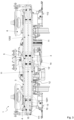
- Fig. 3 shows a representation of a bogie 1 according to the invention with anti-roll supports hinged to the car body (not shown) in section along the Fig. 1 indicated line XX, which corresponds to a longitudinal section along the axis of symmetry of that of the two torsion spring systems 12 of the bogie 1 in which the torsion bar 11 of the anti-roll support is arranged, and thus also of the torsion bar 11 of the anti-roll support.
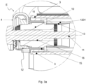
- Fig. 3a shows an enlarged view of detail E from Fig. 3 .
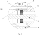
- Fig. 3b shows an enlarged view of detail F from Fig. 3 .
- Fig. 3 shows the space-saving arrangement of the torsion spring system 12 within the frame 3.
- the torsion spring system 12 comprises two torsion bars 1201 and 1202 with the same spring characteristic, which are arranged one behind the other in the axial direction, whereby the longitudinal axes, i.e. the axes with the smallest moment of inertia of both torsion bars 1201 and 1202, coincide.
- an insert 13, 13' e.g. metallic, is arranged at each end, as shown in the Fig. 3a , 3b more clearly visible.
- the torsion bar 1201, 1202 is thickened, ie the wall thickness is increased, for example, by additional fiber layers, or an additional bandage that encloses the torsion bar in this area and is preferably made of a metal.
- the mutually facing end regions of the torsion bars 1201 and 1202 comprise a common insert 13', i.e. the torsion bars 1201 and 1202 of the torsion spring system 12 are connected to one another via a common insert 13'.
- the insert 13' is connected in a rotationally fixed manner to a fixed bearing 14 attached to the frame 3, as shown in more detail in Fig. 2b.
- the inserts 13 of the other, outer end regions of the two torsion bars 1201 and 1202 are firmly connected to the transmission shaft 10, which is rotatably mounted in a radial bearing 15 attached to the frame 3 and is connected to the spring lever arm 4, as Fig. 3a shows the torsion bar 1201 in detail as an example.
- the torsion bars 1201 and 1202, the inserts 13, the fixed bearing 14 and the transmission shaft 10 of the bogie 1 are designed as essentially cylindrical hollow bodies such that the torsion bar 11 of the anti-roll support is arranged according to the invention throughout the inner volume of the elements mentioned, with its longitudinal axis essentially coinciding with the longitudinal axis of the elements.
- the torsion bar 11 of the anti-roll support projects with its two end regions over the transmission shaft 1 Q arranged there, with the torsion bar 11 of the anti-roll support being guided through the transmission shaft 10 by means of a plain bearing bush 16.
- the torsion bar 11 of the anti-roll support is thus rotatably mounted in the transmission shaft 10 in both end regions.
- the end areas of the torsion bar 11 of the anti-roll support are thickened, particularly where the torsion bar 11 is in contact with the plain bearing bush 16, but the end areas can also be designed without any thickening.
- the lever 111 is arranged on the two areas of the torsion bar 11 of the anti-roll support that protrude beyond the respective spring lever arm 4 and are designed as an axial stop. This lever is connected to the pendulum support 112, which is articulated on the car body (not shown) of the rail vehicle.
- Fig. 4 and Fig. 5 show views of a bogie 1* according to the invention analogous to that in Fig. 1 , whereby the bogie 1* has exactly one anti-roll support, which is hinged to one of the two torsion spring systems.
- This embodiment represents an alternative to the Fig. 2 and 3 shown embodiment of a bogie 1.
- Fig. 4 gives the side view of a bogie 1* in the Fig. 1 indicated viewing direction Y.
- the bogie 1* does not have a pendulum support arrangement for linking the anti-roll support 11 to the car body.
- the torsion bar 11 of the anti-roll support which is arranged within the torsion spring system to save space, is partially connected in a rotationally fixed manner to the transmission shaft 10, so that the anti-roll support is linked to the torsion spring system by means of the transmission shaft 10.
- the torsion spring system 12 arranged within the frame 3 also comprises two torsion bars 1201 and 1202 with the same spring characteristic, which are arranged one behind the other in the axial direction, whereby the longitudinal axes, i.e. the axes with the smallest moment of inertia of both torsion bars 1201 and 1202, coincide.
- an insert 13, 13' e.g. made of metal, is arranged at each end.
- the torsion bar 1201, 1202 In the area of the torsion bar 1201, 1202 in which the insert 13, 13' rests, the torsion bar 1201, 1202 is thickened, ie the wall thickness is increased, e.g. by additional fiber layers or bandages.
- the design of the bogie 1* corresponds in the area of the mutually facing end areas of the torsion bars 1201 and 1202 to that in Figure 3b illustrated version of bogie 1.
- Fig. 5a shows the torsion bar 1201 in detail as an example.
- the torsion bars 1201 and 1202, the inserts 13, the fixed bearing 14 and the transmission shaft 10 of the bogie 1* are designed as essentially cylindrical hollow bodies such that the torsion bar 11 of the anti-roll support is arranged according to the invention throughout the inner volume of the elements mentioned, with its longitudinal axis coinciding with the longitudinal axis of the elements, and with the torsion bar 11 not projecting beyond the transmission shaft 10.
- the two end regions of the torsion bar 11 of the anti-roll support which are thickened in the embodiment shown, each have an outer region in the axial direction, pointing towards the spring lever arm 4, which is connected to the transmission shaft 10 in a force-fitting or force-and-form-fitting manner, e.g.
- Fig. 6 shows the side view of a bogie 1** according to the invention in the Fig. 1 indicated viewing direction Y, whereby the bogie 1** differs from the bogie 1* only in that the torsion bar 11 of a roll support is arranged in each of its two torsion spring systems (not visible), thus it has two roll supports, each of which is articulated to a torsion spring system by means of a transmission shaft 10.
- Fig. 6a is the top view of a section in the Fig. 1 to be taken from the XY plane of the bogie 1** according to the invention with the pivot pin 5.
- a torsion bar 11 of a roll support is arranged in each torsion spring system 12 assigned to a wheel set 2.
- Each torsion spring system 12 is connected at the end via an insert 13 to an associated, rotatably mounted transmission shaft 10.
- the torsion bar 11 of the roll support is non-rotatably non-positive or non-positive and positively connected to both end-mounted transmission shafts 10 and by means of these, hinged to the torsion spring system 12 at both of its end areas.
- the bogie 1** advantageously has a particularly large amount of installation space for arranging components such as the motors 7, the gearboxes 8 and the brakes 9.
Landscapes
- Engineering & Computer Science (AREA)
- Mechanical Engineering (AREA)
- Springs (AREA)
- Vehicle Body Suspensions (AREA)
Description
- Die Erfindung betrifft ein Drehgestell nach dem Oberbegriff des Anspruchs 1.
- Konventionelle Drehgestelle für Schienenfahrzeuge in Stahlbauweise, bei denen die Primärfederung, also die Federung der Räder bzw. Radachsen gegenüber dem Drehgestell, zumeist durch Blattfedern, Schraubenfedern oder aufgebracht wird, weisen neben dem hohen Eigengewicht zusätzliche Nachteile dadurch auf, dass sie aus vielen Einzelteilen bestehen und wenig Bauraum für Einbauten wie Antriebe, Steuergeräte und Bremsen vorhanden ist.
- Um das Eigengewicht zu verringern, sind aus dem Stand der Technik Drehgestelle in Faserverbundbauweise bekannt, bei denen die Primärfederung durch den Drehgestellrahmen, wie z. B. in der
DE 29 52 182 A1 beschrieben, oder durch Blattfedern aus einem faserverstärkten Kunststoff (FVK) realisiert wird, wie z.B. aus derUS 2012/0279416 A1 bekannt. - Besondere Vorteile bietet die Verwendung von FVK bei der Gestaltung von auch als Drehstabfedern, Drehstäben oder Torsionsfedern bezeichneten Torsionsstäben aufgrund der Möglichkeit zur belastungsgerechten Faserorientierung, was dazu führt, dass in die Torsionssteifigkeit einer Torsionsfeder aus Faserverbundmaterial das Elastizitäts-Modul E in Längsrichtung der Fasern eingeht und nicht, wie beispielsweise bei metallischen Federn, das i. A. kleinere Schubmodul G.
- Unter anderem aus diesem Grund weisen Drehgestelle, bei denen die Primärfederung mittels Torsionsstäben realisiert wird, hohes Leichtbaupotenzial und Bauraum für Einbauten auf. Ein Drehgestell mit Torsionsstab-Primärfederung, bei dem die Radachsen durch in Höhenrichtung schwingende Lenker am Gestellrahmen befestigt sind, wobei jeder Lenker an dem Außenende eines quer zur Fahrtrichtung angeordneten Torsionsstabs befestigt ist, ist beispielsweise aus der
DE 735 080 A oder aus derDE 10 2016 123 784 A1 bekannt. Eine ähnliche Bauform ist in derDE 838 897 A beschrieben, wobei die Lenker hier über eine einstellbare Verankerung der Torsionsstäbe in der Drehgestellmitte höhenverstellbar sind. - In Schienenfahrzeugen finden Torsionsstäbe eine weitere Anwendung bei der Querstabilisierung des Wagenkastens, also um die Wankbewegung des Wagenkastens um seine Längsachse zu reduzieren bzw. zu stabilisieren.
- Die
DE 28 41 769 A1 zeigt einen als Querstabilisator wirkenden Torsionsstab, der an gegenüberliegenden Fahrzeugseiten angeordnete Schwingen miteinander verbindet. An jeder Schwinge, die über einen Schwingenhalter am Drehgestellrahmen angebracht ist, ist vertilelbeweglich das obere Lager einer Schraubenfeder zur Abfederung des Wagenkastens befestigt. - Zur Behinderung des einseitigen Einfederns des Wagenkastens wird auch häufig eine Wankstütze in Gestalt eines quer zur Fahrtrichtung angeordneten Torsionsstabs mit endseitigen Kurbeln eingesetzt, die zumeist schwenkbar am Wagenkasten gelagert sind, wobei die Verbindung zwischen den Kurbeln und dem Wagenkasten über Pendelstützen erfolgt.
- In der
DE 44 10 970 C1 ist eine Kombination aus einer dergestalt ausgeführten Wankstütze für ein Schienenfahrzeug, dessen Wagenkasten gefedert auf dem Drehgestell aufliegt, mit einer durch Schrägstellen der Pendelstützen der Wankstütze dargestellten passiven Querneigesteuerung beschrieben, bei der der Torsionsstab der Wankstütze aus einer im Drehgestell durch Federkraft zentrierten Mittellage quer zur Fahrzeuglängsrichtung um einen begrenzten Hub nach beiden Seiten verschiebbar gelagert ist. - In der
DE 10 2012 008 995 A1 ist ein Stabilisator aus einem FVK für die Radaufhängung eines Kraftfahrzeugs gezeigt, der mit an der Radaufhängung befestigten Längsarmen über eine kraft- und formschlüssige Verzahnung verbunden ist. - Die
CN 205 059 624 U zeigt einen Anti-Roll-Torsionsstab für den Schienenverkehr, wobei der Anti-Roll-Torsionsstab eine erste Torsionsstabanordnung und eine zweite Torsionsstabanordnung umfasst. Die erste Torsionsstabanordnung umfasst eine erste Torsionsstabachse, einen ersten Torsionsarm, der an der ersten Torsionsstabachse befestigt ist, und einen ersten vertikalen Verbindungsstab, der an dem ersten Torsionsarm befestigt ist. Die zweite Torsionsstabanordnung umfasst eine zweite Torsionsstabachse, einen zweiten Torsionsarm, der an der zweiten Torsionsstabachse befestigt ist, und einen zweiten vertikalen Verbindungsstab, der an dem zweiten Torsionsarm befestigt ist. Die zweite Torsionsstabachse ist über eine Torsionsstabwellenkupplung an der ersten Torsionsstabachse angebracht und koaxial zu dieser, wobei die erste Torsionsstabachse von beiden Enden der zweiten Torsionsstabachse absteht, und wobei der erste Torsionsarm an der Außenseite des zweiten Torsionsarms vorgesehen ist. Die erste Torsionsstabachse ist an der zweiten Torsionsstabachse mit einer Befestigungsbaugruppe angebracht, um den Anti-Roll-Torsionsstab für den Schienenverkehr an einem Drehgestell zu montieren. Ein Schienenfahrzeug kann eine stärkere Anti-Roll-Steifigkeit mit einem zusammengesetzten Anti-Roll-Torsionsstab-System sowie eine stärkere Anti-Roll-Empfindlichkeit haben, um Sicherheitsanforderungen zu erfüllen. - Aufgabe der Erfindung ist es, ein Drehgestell mit Wankstütze anzugeben, das besonders viel Bauraum für zusätzliche Einbauten aufweist.
- Die Aufgabe wird gelöst durch ein Drehgestell für ein Schienenfahrzeug mit den Merkmalen des Anspruchs 1. Weiterbildungen der Erfindung sind in untergeordneten Ansprüchen angegeben.
- Das erfindungsgemäße Drehgestell weist mindestens zwei Radsätze auf, von denen jeder Radsatz zwei mit einer Achse verbundene Räder umfasst. Der Radsatz ist in Achslagern gelagert, die über Achslenker gelenkig mit dem Rahmen verbunden sind, so dass die Achslenker mit den Achslagern und der Rahmen eine H-Form ausbilden. Der Rahmen weist mindestens zwei parallel zu den Achsen der Radsätze angeordnete Torsionsfedersysteme auf, die bereichsweise mit dem Rahmen fest verbunden sind. Weiterhin weisen die Torsionsfedersysteme endseitig Federhebelarme auf, so dass jeweils der nicht mit dem Torsionsfedersystem verbundene Endbereich des Federhebelarms auf das Achslager wirkt. In dem erfindungsgemäßen Drehgestell wird die Primärfederung demnach zumindest teilweise durch die mindestens zwei Torsionsfedersysteme übernommen. Das erfindungsgemäße Drehgestell weist außerdem mindestens eine Wankstütze auf, die einen Torsionsstab aufweist, der torsionsbeweglich im inneren Volumen mindestens eines der Torsionsfedersysteme angeordnet ist. Der Torsionsstab der Wankstütze ist demnach, ebenso wie das Torsionsfedersystem, quer zur Fahrtrichtung des Drehgestells angeordnet, das heißt, die Mittelachse des Torsionsstabs der Wankstütze ist ebenso zumindest annähernd parallel zu den Achsen der Radsätze angeordnet
- Jedes der mindestens zwei Torsionsfedersysteme weist mindestens einen Torsionsstab auf, der als Hohlkörper ausgebildet. Im Sinne dieser Anmeldung kann ein Torsionsfedersystem genau einen Torsionsstab aufweisen, der im Bereich seiner halben Höhe fest im Rahmen gelagert ist und dessen beiden Enden jeweils einen Federhebel aufweisen. Ein Torsionsfedersystem kann ebenso zwei in axialer Richtung nacheinander angeordnete Torsionsstäbe aufweisen. Dann sind die zueinander weisenden Enden der Torsionsstäbe fest am Rahmen gelagert. Die anderen Enden der beiden Torsionsstäbe weisen jeweils einen Federhebel auf.
- Aufgrund der Anordnung des Torsionsstabs der Wankstütze innerhalb des Torsionsfedersystems weist das erfindungsgemäße Drehgestell vorteilhaft einen großen Bauraum für Einbauten auf.
- Der Torsionsstab der Wankstütze wird am Torsionsfedersystem, welches zumindest Teil der Primärfederung des Schienenfahrzeugs ist, angelenkt.
- Besonders platzsparend können die Torsionsfedersysteme in entsprechenden Aussparungen innerhalb des Rahmens angeordnet werden.
- In einer Ausführungsform des erfindungsgemäßen Drehgestells überragen die Endbereiche des Torsionsstabs der Wankstütze das Torsionsfedersystem beidseitig. An jedem der beiden Endbereiche des Torsionsstabs der Wankstütze ist mindestens eine Pendelstützenanordnung angeordnet, deren jeweils nicht mit dem Torsionsstab verbundenes Ende am Wagenkasten des Schienenfahrzeugs angelenkt ist, so dass die beiden Pendelstützenanordnungen an sich gegenüberliegenden Seiten des Wagenkastens mechanisch und energieübertragend angelenkt sind.
- Bevorzugt ist der Torsionsstab der Wankstütze dazu endseitig kraftschlüssig oder kraft- und form schlüssig mit dem Torsionsfedersystem zumindest mittelbar verbunden, beispielsweise über eine endseitige Pressverbindung oder eine endseitige Verzahnung zwischen dem Torsionsstab der Wankstütze und dem Torsionsfedersystem oder zwischen dem Torsionsstab der Wankstütze und einem mit dem Torsionsfedersystem verbundenen Übertragungselement.
- Vorteilhaft bietet diese Ausführungsform besonders viel Bauraum und benötigt besonders wenige Bauteile sowie keine zusätzlichen Anbauten am Wagenkasten.
- Die Geometrie und das Material der Torsionsstäbe des Torsionsfedersystems und der Wankstütze können definiert an die zu erwartenden Lasten angepasst werden. Die Torsionsstäbe können beispielsweise eine runde, ovale oder mehreckige Querschnittsaußenkontur aufweisen, die über die Länge, also entlang der Mittelachse, der Torsionsstäbe konstant oder variabel sein kann. Zur Masseeinsparung wird der Torsionsstab der Wankstütze bevorzugt ebenso als Hohlkörper ausgeführt wie der mindestens eine Torsionsstab eines Torsionsfedersystems. Die Wanddicke der als Hohlkörper ausgeführten Torsionsstäbe kann über die Länge konstant oder variabel ausgeführt sein. Bevorzugt ist die Wanddicke in mechanisch besonders beanspruchten Bereichen der Torsionsstäbe, beispielsweise in den Endbereichen, größer als in anderen Bereichen.
- In einer weiteren Ausführungsform des erfindungsgemäßen Drehgestells besteht der Torsionsstab der Wankstütze zumindest überwiegend aus einem faserverstärkten Kunststoff. Bevorzugt ist zusätzlich zumindest der mindestens eine Torsionsstab der Torsionsfedersysteme des Drehgestells zumindest überwiegend aus einem faserverstärkten Kunststoff. Besonders bevorzugt ist zusätzlich zumindest der Rahmen und/oder die Federhebelarme des Drehgestells zumindest überwiegend aus einem faserverstärkten Kunststoff. Dabei bedeutet "zumindest überwiegend", dass die genannten Bauteile durchaus auch als Hybridstruktur ausgeführt sein können, z. B. durch Einsatz eines metallischen Inserts zur Krafteinleitung, wobei die Hauptfunktion der Torsion durch den Faserverbundanteil ausgeführt wird.
- Als Fasern sind alle Fasern, insbesondere Kohlenstoff- oder Glas- oder Aramidfasern oder eine Kombination aus den vorgenannten, geeignet, die den im Betrieb des Drehgestells auftretenden Belastungen gewachsen sind. Als Harz sind alle Harze, insbesondere Kunstharze, geeignet, die den im Betrieb des Drehgestells auftretenden Belastungen gewachsen sind. Diese sind vom Fachmann in Kenntnis des Erfindungsgedankens ohne Weiteres bestimmbar.
- Mit anderen Worten zusammenfassend basiert die erfindungsgemäße Lösung darauf, dass der quer zur Fahrtrichtung des Drehgestells angeordnete Torsionsstab mindestens einer Wankstütze des Drehgestells in etwa konzentrisch innerhalb des mindestens einen Torsionsstabs eines Torsionsfedersystems, welches zur zumindest teilweisen Primärfederung des Drehgestells ausgebildet ist, torsionsbeweglich angeordnet ist
Die Erfindung wird im Folgenden durch Ausführungsbeispiele anhand von Figuren erläutert, ohne auf diese beschränkt zu sein. In den Figuren ist zwecks besserer Übersichtlichkeit bei mehrfach vorkommenden, gleichen Komponenten jeweils nur eine mit einem Bezugszeichen versehen. - Dabei zeigt die
-
Fig. 1 eine Draufsicht auf ein erfindungsgemäßes Drehgestell für ein Schienenfahrzeug, -
Fig. 2 eine Seitenansicht in Blickrichtung Y eines erfindungsgemäßen Drehgestells mit am Wagenkasten (nicht dargestellt) angelenkter Wankstütze, -
Fig 3 eine Schnittdarstellung entlang der Linie X-X eines erfindungsgemäßen Drehgestells mit am Wagenkasten (nicht dargestellt) angelenkter Wankstütze, -
Fig. 3a das Detail E ausFigur 3 , -
Fig. 3b das Detail F ausFigur 3 , -
Fig. 4 eine Seitenansicht in Blickrichtung Y eines erfindungsgemäßen Drehgestells mit einer durch das Torsionsfedersystem angelenkten Wankstütze, -
Fig. 5 eine Schnittdarstellung entlang der Linie X-X eines erfindungsgemäßen Drehgestells mit einer durch das Torsionsfedersystem angelenkten Wankstütze, -
Fig. 5a das Detail E* ausFigur 5 , -
Fig. 6 eine Seitenansicht in Blickrichtung Y eines erfindungsgemäßen Drehgestells mit zwei jeweils durch ein Torsionsfedersystem angelenkten Wankstützen. -
Fig. 6a eine Draufsicht auf einen Schnitt in der X-Y-Ebene des erfindungsgemäßen Drehgestells ausFigur 6 . -
Fig. 1 zeigt die Draufsicht auf ein Ausführungsbeispiel eines erfindungsgemäßen Drehgestells für ein Schienenfahrzeug. Das Drehgestell 1, 1*, 1** weist zwei in je zwei Achslagern 21 gelagerte Radsätze 2 mit zwei durch eine Achse 201 verbundenen Rädern 202 auf. Jedes Achslager 21 ist über einen Achslenker 22 mit dem Rahmen 3 gelenkig verbunden. Zur Federung der Radsätze 2 gegenüber dem Rahmen 3 weist das Drehgestell 1, 1*, 1** jeweils ein Torsionsfedersystem pro Radsatz 2 auf, das parallel zur Achse 201 des entsprechenden Radsatzes 2 im Rahmen 3 angeordnet und dadurch in der gezeigten Darstellung nicht sichtbar ist. Gleiches gilt für die h1 Torsionsfedersystem angeordnete Wankstütze. Die Anlenkung der Wankstütze ist nicht dargestellt. Am Torsionsfedersystem sind endseitig Federhebelarme 4 angeordnet, wobei jeder Federhebelarm 4 mit seinem einen Endbereich mittels eines Dämpfungskörpers, z. B. eine Gummiunterlage 41, auf ein Achslager 21 wirkt. Als Verbindung zum Wagenkasten (nicht dargestellt) des Schienenfahrzeugs ist ein Drehzapfen 5 auf dem Rahmen 3 angeordnet; eine elastische Verbindung zwischen Wagenkasten und Drehgestell 1, 1*, 1** wird durch auf dem Rahmen 3 angeordnete Luftfedern 6 zur Sekundärfederung hergestellt. - Vorteilhaft weist das Drehgestell 1, 1*, 1** besonders viel Bauraum für weitere betriebsrelevante Einbauten, wie die Motoren 7, die Getriebe 8 und die Bremsen 9 auf.
- Insbesondere der Rahmen 3, die Federhebelarme 4, die Torsionsfedersysteme und der Torsionsstab der Wankstütze können zumindest überwiegend aus einem FVK gefertigt sein.
-
Fig. 2 undFig. 3 zeigen Ansichten eines erfindungsgemäßen Drehgestells analog dem inFig. 1 , wobei die Wankstützen am Wagenkasten (nicht dargestellt) angelenkt sind. -
Fig. 2 zeigt die Seitenansicht eines Drehgestells 1 in der inFig. 1 angegebenen Blickrichtung Y. Wie oben beschrieben, weist das Drehgestell 1 in Achslagern 21 gelagerte Radsätze 2 auf. Jedes Achslager 21 ist über einen Achslenker 22 mit dem Rahmen 3 gelenkig verbunden. Auf jedes Achslager 21 wirkt ein Endbereich eines Federhebelarms 4 über einen Dämpfungskörper, z. B. eine Gummiunterlage 41. Der andere Endbereich des Federhebelarms 4 ist über eine, z. B. metallische, Übertragungswelle 10 mit dem Torsionsfedersystem (nicht sichtbar) verbunden. In einem der beiden Torsionsfedersysteme des Drehgestells 1 ist eine Wankstütze mit einem Torsionsstab 11 angeordnet, der endseitig über eine Pendelstützenanordnung, aufweisend einen einseitigen Hebel 111 und eine im Wesentlichen vertikale Pendelstütze 112 an gegenüberliegenden Seiten des Wagenkastens (nicht dargestellt) des Schienenfahrzeugs, angelenkt ist. -
Fig. 3 zeigt die Darstellung eines erfindungsgemäßen Drehgestells 1 mit am Wagenkasten (nicht dargestellt) angelenkten Wankstützen im Schnitt entlang der inFig. 1 angegebenen Linie X-X, der einem Längsschnitt entlang der Symmetrieachse desjenigen der beiden Torsionsfedersysteme 12 des Drehgestells 1, in dem der Torsionsstab 11 der Wankstütze angeordnet ist, und damit auch des Torsionsstabs 11 der Wankstütze, entspricht.Fig. 3a zeigt eine vergrößerte Ansicht des Details E ausFig. 3 .Fig. 3b zeigt eine vergrößerte Ansicht des Details F ausFig. 3 . -
Fig. 3 zeigt die platzsparende Anordnung des Torsionsfedersystems 12 innerhalb des Rahmens 3. Das Torsionsfedersystem 12 umfasst im dargestellten Ausführungsbeispiel zwei Torsionsstäbe 1201 und 1202 mit gleicher Federkennlinie, die in axialer Richtung hintereinander angeordnet sind, wobei die Längsachsen, also die Achsen mit dem kleinsten Trägheitsmoment beider Torsionsstäbe 1201 und 1202, zusammenfallen. In den Torsionsstäben 1201 und 1202 ist jeweils endseitig ein, z.B. metallisches, Insert 13, 13' angeordnet, wie in denFig. 3a ,3b genauer sichtbar. In dem Bereich des Torsionsstabs 1201, 1202, in dem das Insert 13, 13' anliegt, ist der Torsionsstab 1201, 1202 aufgedickt, d.h. die Wanddicke isi z. B. durch zusätzliche Faserlagen, oder eine zusätzliche Bandage, die den Torsionsstab in diesem Bereich umschließt und vorzugsweise aus einem Metall gefertigt isi vergrößert. - Die zueinander weisenden Endbereiche der Torsionsstäbe 1201 und 1202 umfassen ein gemeinsames Insert 13', d. h., die Torsionsstäbe 1201 und 1202 des Torsionsfedersystems 12 sind über ein gemeinsames Insert 13' miteinander verbunden. Das Insert 13' ist mit einem am Rahmen 3 befestigten Festlager 14 drehfest verbunden, wie in Fig. 2b näher dargestellt. Die Inserts 13 der anderen, äußeren Endbereiche der beiden Torsionsstäbe 1201 und 1202 sind fest mit der Übertragungswelle 10 verbunden, die drehbar in einem, im Rahmen 3 befestigten Radiallager 15 gelagert ist und mit dem Federhebelarm 4 in Verbindung steht, wie
Fig. 3a beispielhaft für den Torsionsstab 1201 im Detail zeigt. - Die Torsionsstäbe 1201 und 1202, die Inserts 13, das Festlager 14 und die Übertragungswelle 10 des Drehgestells 1 sind so als im Wesentlichen zylindrische Hohlkörper ausgebildet, dass der Torsionsstab 11 der Wankstütze erfindungsgemäß durchgängig im inneren Volumen der genannten Elemente angeordnet ist, wobei seine Längsachse im Wesentlichen mit der Längsachse der Elemente zusammenfällt. Der Torsionsstab 11 der Wankstütze überragt mit seinen beiden Endbereichen jeweils die dort angeordnete Übertragungswelle 1 Q wobei der Torsionsstab 11 der Wankstütze mittels einer Gleitlagerbuchse 16 durch die Übertragungswelle 10 geführt wird. Der Torsionsstab 11 der Wankstütze ist damit in beiden Endbereichen drehbar in der Übertragungswelle 10 gelagert. Im gezeigten Ausführungsbeispiel sind die Endbereiche des Torsionsstabs 11 der Wankstütze insbesondere dort, wo der Torsionsstab 11 mit der Gleitlagerbuchse 16 in Kontakt steht, aufgedicki die Endbereiche können aber auch ohne Aufdickung ausgeführt sein. An den beiden, den jeweiligen Federhebelarm 4 überragenden Bereichen des Torsionsstabs 11 der Wankstütze, die als axialer Anschlag ausgebildet sind, ist der Hebel 111 angeordnet, der mit der Pendelstütze 112 verbunden ist, die am Wagenkasten (nicht dargestellt) des Schienenfahrzeugs angelenkt ist.
-
Fig. 4 undFig. 5 zeigen Ansichten eines erfindungsgemäßen Drehgestells 1* analog dem inFig. 1 , wobei das Drehgestell 1* genau eine Wankstütze aufweist, die an einem der beiden Torsionsfedersysteme angelenkt ist. Dieses Ausführungsbeispiel stellt eine Alternative zu dem inFig. 2 und3 gezeigten Ausführungsbeispiel eines Drehgestells 1 dar. -
Fig. 4 gibt die Seitenansicht eines Drehgestells 1* in der inFig. 1 angegebenen Blickrichtung Y wieder. Neben den bereits inFig. 2 gekennzeichneten Komponenten weist das Drehgestell 1* im Gegensatz zum Drehgestell 1 keine Pendelstützenanordnung zur Anlenkung der Wankstütze 11 am Wagenkasten auf. Stattdessen ist der platzsparend innerhalb des Torsionsfedersystems angeordnete Torsionsstab 11 der Wankstütze bereichsweise drehfest mit der Übertragungswelle 10 verbunden, so dass die Wankstütze mittels der Übertragungswelle 10 am Torsionsfedersystem angelenkt ist. - Dies ist in
Fig. 5 , der Darstellung des erfindungsgemäßen Drehgestells 1* im Schnitt entlang der inFig. 1 angegebenen Linie X-X, bzw. in Fig. Sa, die eine vergrößerte Ansicht des Details E* ausFig. 5 zeigt, genauer zu sehen. Auch in diesem Ausführungsbeispiel umfasst das innerhalb des Rahmens 3 angeordnete Torsionsfedersystem 12 zwei Torsionsstäbe 1201 und 1202 mit gleicher Federkennlinie, die in axialer Richtung hintereinander angeordnet sind, wobei die Längsachsen, also die Achsen mit dem kleinsten Trägheitsmoment beider Torsionsstäbe 1201 und 1202, zusammenfallen. In den Torsionsstäben 1201 und 1202 ist jeweils endseitig ein, z. B. metallisches, Insert 13, 13' angeordnet. In dem Bereich des Torsionsstabs 1201, 1202, in dem das Insert 13, 13' anliegt, ist der Torsionsstab 1201, 1202 aufgedickt, d.h. die Wanddicke ist, z. B. durch zusätzliche Faserlagen oder Bandagen, vergrößert. Die Ausführung des Drehgestells 1* entspricht im Bereich der zueinander weisenden Endbereiche der Torsionsstäbe 1201 und 1202 der inFigur 3b dargestellten Ausführung des Drehgestells 1. - Ebenfalls wie bei dem Drehgestell 1 sind auch im Drehgestell 1* de Inserts 13 der anderen, äußeren Endbereiche der beiden Torsionsstäbe 1201 und 1202 fest mit der Übertragungswelle 10 verbunden, die drehbar in einem im Rahmen 3 befestigten Radiallager 15 gelagert ist und mit dem Federhebelarm 4 in Verbindung steht wie
Fig. 5a beispielhaft für den Torsionsstab 1201 im Detail zeigt. - Die Torsionsstäbe 1201 und 1202, die Inserts 13, das Festlager 14 und die Übertragungswelle 10 des Drehgestells 1* sind so als im Wesentlichen zylindrische Hohlkörper ausgebildet, dass der Torsionsstab 11 der Wankstütze erfindungsgemäß durchgängig im inneren Voumen der genannten Elemente angeordnet ist, wobei seine Längsachse mit der Längsachse der Elemente zusammenfällt, und wobei der Torsionsstab 11 die Übertragungswelle 10 nicht überragt. Die beiden im gezeigten Ausführungsbeispiel aufgedickten Endbereiche des Torsionsstabs 11 der Wankstütze weisen jeweils einen in axialer Richtung äußeren, zum Federhebelarm 4 weisenden Bereich auf, der kraftschlüssig oder kraft- und formschlüssig, z. B. über eine Verzahnung 17, drehfest mit der Übertragungswelle 10 verbunden ist. An die Verzahnung 17 schließt sich in axialer Richtung weiter innenliegend ein nichtverzahnter Bereich des Torsionsstabs 11 an, der beispielsweise mittels einer Gleitlagerbuchse 16 durch die Übertragungswelle 10 geführt wird. Sowohl das Torsionsfedersystem 12 als auch der Torsionsstab 11 der Wankstütze sind dementsprechend jeweils endseitig drehfest mit der jeweiligen Übertragungswelle 10 verbunden, so dass die Wankstütze mittels der Übertragungswelle 10 am Torsionsfedersystem 12 angelenkt ist.
-
Fig. 6 zeigt die Seitenansicht eines erfindungsgemäßen Drehgestells 1** in der inFig. 1 angegebenen Blickrichtung Y, wobei sich das Drehgestell 1** nur insofern von dem Drehgestell 1* unterscheidet, als dass in jedem seiner beiden Torsionsfedersysteme (ncht sichtbar) der Torsionsstab 11 einer Wankstütze angeordnet ist, es also zwei Wankstützen aufweist, die jeweils mittels einer Übertragungswelle 10 an einem Torsionsfedersystem angelenkt sind. - In
Fig. 6a ist die Draufsicht auf einen Schnitt in derFig. 1 zu entnehmenden X-Y-Ebene des erfindungsgemäßen Drehgestells 1** mit dem Drehzapfen 5 dargestellt. In jedem, jeweils einem Radsatz 2 zugeordneten Torsionsfedersystem 12 ist jeweils ein Torsionsstab 11 einer Wankstütze angeordnet. Jedes Torsionsfedersystem 12 ist jeweils endseitig über ein Insert 13 mit einer zugehörigen, drehbar gelagerten Übertragungswelle 10 verbunden. Der Torsionsstab 11 der Wankstütze ist drehfest kraftschlüssig oder kraft- und formschlüssig mit beiden endseitig angeordneten Übertragungswellen 10 verbunden und mittels dieser an seinen beiden Endbereichen am Torsionsfedersystem 12 angelenkt. Das Drehgestell 1** verfügt vorteilhaft über besonders viel Bauraum zur Anordnung von Komponenten wie z. B. den Motoren 7, den Getrieben 8 und den Bremsen 9.
Claims (5)
- Drehgestell (1, 1*, 1**) für ein Schienenfahrzeug mit mindestens zwei in Achslagern (21) gelagerten Radsätzen (2) und wenigstens einem Rahmen (3), wobei jedes der zwei Achslager (21) eines Radsatzes (2) über einen Achslenker (22) mit dem Rahmen (3) gelenkig verbunden ist, aufweisend mindestens zwei parallel zu den Achsen (201) der Radsätze (2) angeordnete Torsionsfedersysteme (12), die jeweils mindestens einen Bereich aufweisen, in dem sie mit dem Rahmen (3) drehfest verbunden sind, wobei jedes Torsionsfedersystem (12) zwei Federhebelarme (4) derart aufweist, dass der nicht mit dem Torsionsfedersystem (12) verbundene Endbereich eines Federhebelarms (4) auf das Achslager (21) wirkt, dadurch gekennzeichnet, dass das Drehgestell (1, 1*, 1**) mindestens eine Wankstütze, aufweisend einen Torsionsstab (11), der torsionsbeweglich im inneren Volumen mindestens eines der Torsionsfedersysteme (12) angeordnet ist, aufweist und der Torsionsstab (11) der Wankstütze am Torsionsfedersystem (12) angelenkt ist, wobei in den beiden Endbereichen und im Bereich der halben Höhe des Torsionsfedersystems (12) ein Insert (13, 13') drehfest mit dem Torsionsfedersystem (12) verbunden ist, wobei das Insert (13') im Bereich der halben Höhe des Torsionsfedersystems (12) drehfest in einem Festlager (14) gelagert ist, welches im Rahmen (3) angeordnet ist, und wobei das jeweils eine Insert (13) in einem der beiden Endbereiche des Torsionsfedersystems (12) drehfest mit einer Übertragungswelle (10) verbunden ist, die ihrerseits drehbar in einem im Rahmen (3) angeordneten Radiallager (15) gelagert ist und mit dem zugehörigen Federhebelarm (4) in Verbindung steht, und wobei zumindest das Torsionsfedersystem (12), die Inserts (13, 13'), das Festlager (14) und die Übertragungswelle (10) so als Hohlkörper ausgebildet sind, dass der Torsionsstab (11) der Wankstütze durchgängig in ihrem inneren Volumen angeordnet ist, wobei der Torsionsstab (11) der Wankstütze jeweils in seinen Endbereichen mittels einer Pressverbindung oder Verzahnung drehfest mit der Übertragungswelle (10) verbunden ist, sodass die Wankstütze mittels der Übertragungswelle (10) am Torsionsfedersystem (12) angelenkt ist.
- Drehgestell (1, 1*, 1**) nach Anspruch 1, dadurch gekennzeichnet, dass die Endbereiche des Torsionsstabs (11) der Wankstütze das Torsionsfedersystem (12) überragen und der Torsionsstab (11) der Wankstütze über jeweils eine endseitig angeordnete Pendelstützenanordnung (111, 112) an einander gegenüberliegenden Außenseiten des Wagenkastens des Schienenfahrzeugs angelenkt ist.
- Drehgestell (1, 1*, 1**) nach Anspruch 1, dadurch gekennzeichnet, dass der Torsionsstab (11) der Wankstütze mit dem Torsionsfedersystem (12) zumindest mittelbar in seinen beiden Endbereichen über einen Kraftschluss oder Kraft- und Formschluss verbunden ist.
- Drehgestell (1, 1*, 1**) nach einem der vorangegangenen Ansprüche, dadurch gekennzeichnet, dass der Torsionsstab (11) der Wankstütze zumindest überwiegend aus einem faserverstärkten Kunststoff gefertigt ist.
- Drehgestell (1, 1*, 1**) nach Anspruch 4, dadurch gekennzeichnet, dass der mindestens eine Torsionsstab (1201, 1202) jedes Torsionsfedersystems (12) oder der Rahmen (3) oder die Federhebelarme (4) oder eine Kombination aus den vorgenannten zumindest überwiegend aus einem faserverstärkten Kunststoff gefertigt ist.
Applications Claiming Priority (2)
| Application Number | Priority Date | Filing Date | Title |
|---|---|---|---|
| DE102020109930.4A DE102020109930A1 (de) | 2020-04-09 | 2020-04-09 | Drehgestell für ein Schienenfahrzeug mit Wankstütze |
| PCT/EP2021/058170 WO2021204583A1 (de) | 2020-04-09 | 2021-03-29 | Drehgestell für ein schienenfahrzeug mit wankstütze |
Publications (2)
| Publication Number | Publication Date |
|---|---|
| EP4132833A1 EP4132833A1 (de) | 2023-02-15 |
| EP4132833B1 true EP4132833B1 (de) | 2024-11-20 |
Family
ID=75396738
Family Applications (1)
| Application Number | Title | Priority Date | Filing Date |
|---|---|---|---|
| EP21716655.2A Active EP4132833B1 (de) | 2020-04-09 | 2021-03-29 | Drehgestell für ein schienenfahrzeug mit wankstütze |
Country Status (6)
| Country | Link |
|---|---|
| US (1) | US12637116B2 (de) |
| EP (1) | EP4132833B1 (de) |
| JP (1) | JP7483043B2 (de) |
| DE (1) | DE102020109930A1 (de) |
| ES (1) | ES2998480T3 (de) |
| WO (1) | WO2021204583A1 (de) |
Families Citing this family (1)
| Publication number | Priority date | Publication date | Assignee | Title |
|---|---|---|---|---|
| CN119099672B (zh) * | 2024-10-22 | 2026-04-21 | 中车青岛四方机车车辆股份有限公司 | 一种转向架构架、转向架及拖车车辆 |
Family Cites Families (19)
| Publication number | Priority date | Publication date | Assignee | Title |
|---|---|---|---|---|
| US2191408A (en) * | 1937-04-10 | 1940-02-20 | James C Maris | Engine truck stabilizer |
| DE735080C (de) | 1937-06-19 | 1943-05-06 | Christoph & Unmack Ag | Drehgestell fuer Schienenfahrzeuge |
| CH252265A (de) | 1946-02-13 | 1947-12-15 | Schweiz Ind Ges | Drehgestell für Schienenfahrzeuge mit am gefederten Drehgestellrahmen befestigten Motoren. |
| DE2841769A1 (de) | 1978-09-26 | 1980-04-03 | Daimler Benz Ag | Spurgebundenes fahrzeug mit neigbarem fahrzeugaufbau |
| DE2952182C2 (de) | 1979-12-22 | 1983-02-03 | Messerschmitt-Bölkow-Blohm GmbH, 8000 München | Drehgestell für ein Schienenfahrzeug |
| JPS6117730A (ja) | 1984-07-02 | 1986-01-25 | Nhk Spring Co Ltd | ト−シヨンバ− |
| CH677763A5 (en) * | 1988-12-12 | 1991-06-28 | Inventio Ag | Anti-rocking suspension for rail vehicle - has torsion bar end levers acting against opposite ends of damper |
| US5222442A (en) * | 1992-07-30 | 1993-06-29 | Trans-Dyne Incorporated | Torsion bar railway truck |
| DE4311521C1 (de) | 1993-04-07 | 1994-04-21 | Talbot Waggonfab | Wankstütze für Schienenfahrzeuge |
| DE4410970C1 (de) | 1994-03-29 | 1995-07-20 | Talbot Waggonfab | Wankstütze für Schienenfahrzeuge mit einer Querneigeeinrichtung |
| JPH0924826A (ja) | 1995-07-14 | 1997-01-28 | Nippon Sharyo Seizo Kaisha Ltd | 鉄道車両の車体支持装置 |
| BRPI0916211B1 (pt) * | 2008-07-16 | 2020-02-18 | Electro-Motive Diesel, Inc. | Sistema autodirecional para um truque radial de um veículo ferroviário |
| JP5433080B2 (ja) | 2011-04-07 | 2014-03-05 | 川崎重工業株式会社 | 鉄道車両用台車 |
| DE102011085029A1 (de) | 2011-10-21 | 2013-04-25 | Luhn & Pulvermacher - Dittmann & Neuhaus GmbH | Stabilisator in Faserkunststoffverbund und Verfahren zu dessen Herstellung |
| DE102012008995A1 (de) | 2012-03-02 | 2013-09-05 | Audi Ag | Stabilisator für ein Kraftfahrzeug |
| CN203005448U (zh) * | 2012-12-28 | 2013-06-19 | 南车青岛四方机车车辆股份有限公司 | 无摇枕城际轨道车辆转向架 |
| CN205059624U (zh) | 2015-11-02 | 2016-03-02 | 株洲时代新材料科技股份有限公司 | 轨道交通用复合抗侧滚扭杆系统 |
| CN106627635B (zh) | 2015-11-02 | 2019-01-22 | 株洲时代新材料科技股份有限公司 | 一种复合材料车辆抗侧滚扭杆 |
| DE102016123784A1 (de) | 2016-12-08 | 2018-06-14 | CG Rail - Chinesisch-Deutsches Forschungs- und Entwicklungszentrum für Bahn- und Verkehrstechnik Dresden GmbH | Drehgestell eines Schienenfahrzeugs mit mindestens zwei in Achslagern gelagerten Radsätzen und wenigstens einem Querträger |
-
2020
- 2020-04-09 DE DE102020109930.4A patent/DE102020109930A1/de not_active Withdrawn
-
2021
- 2021-03-29 US US17/995,769 patent/US12637116B2/en active Active
- 2021-03-29 EP EP21716655.2A patent/EP4132833B1/de active Active
- 2021-03-29 WO PCT/EP2021/058170 patent/WO2021204583A1/de not_active Ceased
- 2021-03-29 JP JP2022561994A patent/JP7483043B2/ja active Active
- 2021-03-29 ES ES21716655T patent/ES2998480T3/es active Active
Also Published As
| Publication number | Publication date |
|---|---|
| WO2021204583A1 (de) | 2021-10-14 |
| US20230166777A1 (en) | 2023-06-01 |
| JP2023523699A (ja) | 2023-06-07 |
| EP4132833A1 (de) | 2023-02-15 |
| US12637116B2 (en) | 2026-05-26 |
| ES2998480T3 (en) | 2025-02-20 |
| DE102020109930A1 (de) | 2021-10-14 |
| JP7483043B2 (ja) | 2024-05-14 |
Similar Documents
| Publication | Publication Date | Title |
|---|---|---|
| EP3551519B1 (de) | Drehgestell eines schienenfahrzeugs mit mindestens zwei in achslagern gelagerten radsätzen und wenigstens einem querträger | |
| DE102014205632B4 (de) | Einzelradaufhängung sowie Hinterachse mit Einzelradaufhängungen für ein Fahrzeug und entsprechend ausgestattetes Fahrzeug | |
| DE102012005395B4 (de) | Federungsanordnung für eine Radaufhängung eines Kraftfahrzeuges | |
| EP3411278B1 (de) | Fahrwerk für ein schienenfahrzeug | |
| DE102017222487B3 (de) | Mehrlenkerachse für ein Fahrzeug | |
| EP0547188B1 (de) | Drehgestell für schnellauffähige schienenfahrzeuge | |
| WO2011072652A1 (de) | Blattfederanordnung | |
| EP1915283B1 (de) | Fahrzeug mit wankstützen | |
| DE102014205635A1 (de) | Einzelradaufhängung sowie Hinterachse mit Einzelradaufhängungen für ein Fahrzeug und entsprechend ausgestattetes Fahrzeug | |
| DE202014101432U1 (de) | Einzelradaufhängung sowie Hinterachse mit Einzelradaufhängungen für ein Fahrzeug und entsprechend ausgestattetes Fahrzeug | |
| WO2022069287A1 (de) | Fahrzeugachse und fahrzeug | |
| EP0831003A2 (de) | Drehgestellanbindung für Jacobs-Drehgestelle | |
| EP4132833A1 (de) | Drehgestell für ein schienenfahrzeug mit wankstütze | |
| DE3624537A1 (de) | Radaufhaengung fuer fahrzeuge | |
| DE102017211277A1 (de) | Radaufhängung für ein Kraftfahrzeug | |
| DE19548437C1 (de) | Zweiachsiges Schienenfahrzeug-Drehgestell | |
| EP1897777B1 (de) | Drehgestell | |
| EP4263316B1 (de) | Anordnung aus einem kinematikpaket und einem federhebel für ein drehgestell | |
| DE102014200420B4 (de) | Einzelradaufhängung sowie Hinterachsmodul mit Einzelradaufhängungen für ein Fahrzeug und entsprechend ausgestattetes Fahrzeug | |
| DE4118366C2 (de) | Drehgestell | |
| EP0689980A1 (de) | Verbindungseinrichtung zwischen benachbarten Wagenkästen eines Schienengliederzuges, insbesondere zwischen niederflurigen Strassenbahnwagen | |
| EP1897776B1 (de) | Drehgestell | |
| DE102017128598B4 (de) | Anordnung zum Dämpfen des Wankens und zum Querstabilisieren eines Wagenkastens für Landfahrzeuge | |
| DE202004013292U1 (de) | Drehgestell für Schienenfahrzeuge | |
| EP4686636A1 (de) | Wankstabilisator |
Legal Events
| Date | Code | Title | Description |
|---|---|---|---|
| STAA | Information on the status of an ep patent application or granted ep patent |
Free format text: STATUS: UNKNOWN |
|
| STAA | Information on the status of an ep patent application or granted ep patent |
Free format text: STATUS: THE INTERNATIONAL PUBLICATION HAS BEEN MADE |
|
| PUAI | Public reference made under article 153(3) epc to a published international application that has entered the european phase |
Free format text: ORIGINAL CODE: 0009012 |
|
| STAA | Information on the status of an ep patent application or granted ep patent |
Free format text: STATUS: REQUEST FOR EXAMINATION WAS MADE |
|
| 17P | Request for examination filed |
Effective date: 20221027 |
|
| AK | Designated contracting states |
Kind code of ref document: A1 Designated state(s): AL AT BE BG CH CY CZ DE DK EE ES FI FR GB GR HR HU IE IS IT LI LT LU LV MC MK MT NL NO PL PT RO RS SE SI SK SM TR |
|
| DAV | Request for validation of the european patent (deleted) | ||
| DAX | Request for extension of the european patent (deleted) | ||
| GRAP | Despatch of communication of intention to grant a patent |
Free format text: ORIGINAL CODE: EPIDOSNIGR1 |
|
| STAA | Information on the status of an ep patent application or granted ep patent |
Free format text: STATUS: GRANT OF PATENT IS INTENDED |
|
| INTG | Intention to grant announced |
Effective date: 20240617 |
|
| GRAS | Grant fee paid |
Free format text: ORIGINAL CODE: EPIDOSNIGR3 |
|
| GRAA | (expected) grant |
Free format text: ORIGINAL CODE: 0009210 |
|
| STAA | Information on the status of an ep patent application or granted ep patent |
Free format text: STATUS: THE PATENT HAS BEEN GRANTED |
|
| AK | Designated contracting states |
Kind code of ref document: B1 Designated state(s): AL AT BE BG CH CY CZ DE DK EE ES FI FR GB GR HR HU IE IS IT LI LT LU LV MC MK MT NL NO PL PT RO RS SE SI SK SM TR |
|
| REG | Reference to a national code |
Ref country code: GB Ref legal event code: FG4D Free format text: NOT ENGLISH |
|
| REG | Reference to a national code |
Ref country code: CH Ref legal event code: EP |
|
| REG | Reference to a national code |
Ref country code: DE Ref legal event code: R096 Ref document number: 502021005868 Country of ref document: DE |
|
| REG | Reference to a national code |
Ref country code: IE Ref legal event code: FG4D Free format text: LANGUAGE OF EP DOCUMENT: GERMAN |
|
| REG | Reference to a national code |
Ref country code: ES Ref legal event code: FG2A Ref document number: 2998480 Country of ref document: ES Kind code of ref document: T3 Effective date: 20250220 |
|
| REG | Reference to a national code |
Ref country code: LT Ref legal event code: MG9D |
|
| REG | Reference to a national code |
Ref country code: NL Ref legal event code: MP Effective date: 20241120 |
|
| PG25 | Lapsed in a contracting state [announced via postgrant information from national office to epo] |
Ref country code: PT Free format text: LAPSE BECAUSE OF FAILURE TO SUBMIT A TRANSLATION OF THE DESCRIPTION OR TO PAY THE FEE WITHIN THE PRESCRIBED TIME-LIMIT Effective date: 20250320 Ref country code: IS Free format text: LAPSE BECAUSE OF FAILURE TO SUBMIT A TRANSLATION OF THE DESCRIPTION OR TO PAY THE FEE WITHIN THE PRESCRIBED TIME-LIMIT Effective date: 20250320 Ref country code: HR Free format text: LAPSE BECAUSE OF FAILURE TO SUBMIT A TRANSLATION OF THE DESCRIPTION OR TO PAY THE FEE WITHIN THE PRESCRIBED TIME-LIMIT Effective date: 20241120 |
|
| PG25 | Lapsed in a contracting state [announced via postgrant information from national office to epo] |
Ref country code: FI Free format text: LAPSE BECAUSE OF FAILURE TO SUBMIT A TRANSLATION OF THE DESCRIPTION OR TO PAY THE FEE WITHIN THE PRESCRIBED TIME-LIMIT Effective date: 20241120 Ref country code: NL Free format text: LAPSE BECAUSE OF FAILURE TO SUBMIT A TRANSLATION OF THE DESCRIPTION OR TO PAY THE FEE WITHIN THE PRESCRIBED TIME-LIMIT Effective date: 20241120 |
|
| PG25 | Lapsed in a contracting state [announced via postgrant information from national office to epo] |
Ref country code: BG Free format text: LAPSE BECAUSE OF FAILURE TO SUBMIT A TRANSLATION OF THE DESCRIPTION OR TO PAY THE FEE WITHIN THE PRESCRIBED TIME-LIMIT Effective date: 20241120 |
|
| PG25 | Lapsed in a contracting state [announced via postgrant information from national office to epo] |
Ref country code: NO Free format text: LAPSE BECAUSE OF FAILURE TO SUBMIT A TRANSLATION OF THE DESCRIPTION OR TO PAY THE FEE WITHIN THE PRESCRIBED TIME-LIMIT Effective date: 20250220 |
|
| PG25 | Lapsed in a contracting state [announced via postgrant information from national office to epo] |
Ref country code: GR Free format text: LAPSE BECAUSE OF FAILURE TO SUBMIT A TRANSLATION OF THE DESCRIPTION OR TO PAY THE FEE WITHIN THE PRESCRIBED TIME-LIMIT Effective date: 20250221 Ref country code: LV Free format text: LAPSE BECAUSE OF FAILURE TO SUBMIT A TRANSLATION OF THE DESCRIPTION OR TO PAY THE FEE WITHIN THE PRESCRIBED TIME-LIMIT Effective date: 20241120 |
|
| PGFP | Annual fee paid to national office [announced via postgrant information from national office to epo] |
Ref country code: AT Payment date: 20250417 Year of fee payment: 5 |
|
| PG25 | Lapsed in a contracting state [announced via postgrant information from national office to epo] |
Ref country code: PL Free format text: LAPSE BECAUSE OF FAILURE TO SUBMIT A TRANSLATION OF THE DESCRIPTION OR TO PAY THE FEE WITHIN THE PRESCRIBED TIME-LIMIT Effective date: 20241120 |
|
| PG25 | Lapsed in a contracting state [announced via postgrant information from national office to epo] |
Ref country code: RS Free format text: LAPSE BECAUSE OF FAILURE TO SUBMIT A TRANSLATION OF THE DESCRIPTION OR TO PAY THE FEE WITHIN THE PRESCRIBED TIME-LIMIT Effective date: 20250220 |
|
| PG25 | Lapsed in a contracting state [announced via postgrant information from national office to epo] |
Ref country code: SM Free format text: LAPSE BECAUSE OF FAILURE TO SUBMIT A TRANSLATION OF THE DESCRIPTION OR TO PAY THE FEE WITHIN THE PRESCRIBED TIME-LIMIT Effective date: 20241120 |
|
| PG25 | Lapsed in a contracting state [announced via postgrant information from national office to epo] |
Ref country code: DK Free format text: LAPSE BECAUSE OF FAILURE TO SUBMIT A TRANSLATION OF THE DESCRIPTION OR TO PAY THE FEE WITHIN THE PRESCRIBED TIME-LIMIT Effective date: 20241120 |
|
| PG25 | Lapsed in a contracting state [announced via postgrant information from national office to epo] |
Ref country code: EE Free format text: LAPSE BECAUSE OF FAILURE TO SUBMIT A TRANSLATION OF THE DESCRIPTION OR TO PAY THE FEE WITHIN THE PRESCRIBED TIME-LIMIT Effective date: 20241120 |
|
| PG25 | Lapsed in a contracting state [announced via postgrant information from national office to epo] |
Ref country code: RO Free format text: LAPSE BECAUSE OF FAILURE TO SUBMIT A TRANSLATION OF THE DESCRIPTION OR TO PAY THE FEE WITHIN THE PRESCRIBED TIME-LIMIT Effective date: 20241120 |
|
| PG25 | Lapsed in a contracting state [announced via postgrant information from national office to epo] |
Ref country code: SK Free format text: LAPSE BECAUSE OF FAILURE TO SUBMIT A TRANSLATION OF THE DESCRIPTION OR TO PAY THE FEE WITHIN THE PRESCRIBED TIME-LIMIT Effective date: 20241120 |
|
| PG25 | Lapsed in a contracting state [announced via postgrant information from national office to epo] |
Ref country code: CZ Free format text: LAPSE BECAUSE OF FAILURE TO SUBMIT A TRANSLATION OF THE DESCRIPTION OR TO PAY THE FEE WITHIN THE PRESCRIBED TIME-LIMIT Effective date: 20241120 |
|
| PG25 | Lapsed in a contracting state [announced via postgrant information from national office to epo] |
Ref country code: IT Free format text: LAPSE BECAUSE OF FAILURE TO SUBMIT A TRANSLATION OF THE DESCRIPTION OR TO PAY THE FEE WITHIN THE PRESCRIBED TIME-LIMIT Effective date: 20241120 |
|
| REG | Reference to a national code |
Ref country code: DE Ref legal event code: R097 Ref document number: 502021005868 Country of ref document: DE |
|
| PG25 | Lapsed in a contracting state [announced via postgrant information from national office to epo] |
Ref country code: SE Free format text: LAPSE BECAUSE OF FAILURE TO SUBMIT A TRANSLATION OF THE DESCRIPTION OR TO PAY THE FEE WITHIN THE PRESCRIBED TIME-LIMIT Effective date: 20241120 |
|
| PLBE | No opposition filed within time limit |
Free format text: ORIGINAL CODE: 0009261 |
|
| STAA | Information on the status of an ep patent application or granted ep patent |
Free format text: STATUS: NO OPPOSITION FILED WITHIN TIME LIMIT |
|
| PG25 | Lapsed in a contracting state [announced via postgrant information from national office to epo] |
Ref country code: MC Free format text: LAPSE BECAUSE OF FAILURE TO SUBMIT A TRANSLATION OF THE DESCRIPTION OR TO PAY THE FEE WITHIN THE PRESCRIBED TIME-LIMIT Effective date: 20241120 |
|
| 26N | No opposition filed |
Effective date: 20250821 |
|
| PG25 | Lapsed in a contracting state [announced via postgrant information from national office to epo] |
Ref country code: LU Free format text: LAPSE BECAUSE OF NON-PAYMENT OF DUE FEES Effective date: 20250329 |
|
| GBPC | Gb: european patent ceased through non-payment of renewal fee |
Effective date: 20250329 |
|
| REG | Reference to a national code |
Ref country code: BE Ref legal event code: MM Effective date: 20250331 |
|
| PG25 | Lapsed in a contracting state [announced via postgrant information from national office to epo] |
Ref country code: GB Free format text: LAPSE BECAUSE OF NON-PAYMENT OF DUE FEES Effective date: 20250329 |
|
| PG25 | Lapsed in a contracting state [announced via postgrant information from national office to epo] |
Ref country code: BE Free format text: LAPSE BECAUSE OF NON-PAYMENT OF DUE FEES Effective date: 20250331 |
|
| PG25 | Lapsed in a contracting state [announced via postgrant information from national office to epo] |
Ref country code: IE Free format text: LAPSE BECAUSE OF NON-PAYMENT OF DUE FEES Effective date: 20250329 |
|
| REG | Reference to a national code |
Ref country code: CH Ref legal event code: U11 Free format text: ST27 STATUS EVENT CODE: U-0-0-U10-U11 (AS PROVIDED BY THE NATIONAL OFFICE) Effective date: 20260401 |
|
| PGFP | Annual fee paid to national office [announced via postgrant information from national office to epo] |
Ref country code: DE Payment date: 20260320 Year of fee payment: 6 |
|
| PGFP | Annual fee paid to national office [announced via postgrant information from national office to epo] |
Ref country code: FR Payment date: 20260105 Year of fee payment: 6 |
|
| PG25 | Lapsed in a contracting state [announced via postgrant information from national office to epo] |
Ref country code: CY Free format text: LAPSE BECAUSE OF FAILURE TO SUBMIT A TRANSLATION OF THE DESCRIPTION OR TO PAY THE FEE WITHIN THE PRESCRIBED TIME-LIMIT Effective date: 20241120 |
|
| PG25 | Lapsed in a contracting state [announced via postgrant information from national office to epo] |
Ref country code: LT Free format text: LAPSE BECAUSE OF FAILURE TO SUBMIT A TRANSLATION OF THE DESCRIPTION OR TO PAY THE FEE WITHIN THE PRESCRIBED TIME-LIMIT Effective date: 20241120 |
|
| PG25 | Lapsed in a contracting state [announced via postgrant information from national office to epo] |
Ref country code: TR Free format text: LAPSE BECAUSE OF FAILURE TO SUBMIT A TRANSLATION OF THE DESCRIPTION OR TO PAY THE FEE WITHIN THE PRESCRIBED TIME-LIMIT Effective date: 20241120 |
|
| PGFP | Annual fee paid to national office [announced via postgrant information from national office to epo] |
Ref country code: ES Payment date: 20260420 Year of fee payment: 6 |
|
| PGFP | Annual fee paid to national office [announced via postgrant information from national office to epo] |
Ref country code: CH Payment date: 20260401 Year of fee payment: 6 |