EP4131899B1 - Elektronische vorrichtung - Google Patents
Elektronische vorrichtung Download PDFInfo
- Publication number
- EP4131899B1 EP4131899B1 EP21782202.2A EP21782202A EP4131899B1 EP 4131899 B1 EP4131899 B1 EP 4131899B1 EP 21782202 A EP21782202 A EP 21782202A EP 4131899 B1 EP4131899 B1 EP 4131899B1
- Authority
- EP
- European Patent Office
- Prior art keywords
- fitting part
- caliper
- electronic device
- elastic member
- housing
- Prior art date
- Legal status (The legal status is an assumption and is not a legal conclusion. Google has not performed a legal analysis and makes no representation as to the accuracy of the status listed.)
- Active
Links
Images


Classifications
-
- H—ELECTRICITY
- H04—ELECTRIC COMMUNICATION TECHNIQUE
- H04M—TELEPHONIC COMMUNICATION
- H04M1/00—Substation equipment, e.g. for use by subscribers
- H04M1/02—Constructional features of telephone sets
- H04M1/0202—Portable telephone sets, e.g. cordless phones, mobile phones or bar type handsets
- H04M1/026—Details of the structure or mounting of specific components
-
- G—PHYSICS
- G06—COMPUTING OR CALCULATING; COUNTING
- G06F—ELECTRIC DIGITAL DATA PROCESSING
- G06F1/00—Details not covered by groups G06F3/00 - G06F13/00 and G06F21/00
- G06F1/16—Constructional details or arrangements
- G06F1/1613—Constructional details or arrangements for portable computers
- G06F1/1633—Constructional details or arrangements of portable computers not specific to the type of enclosures covered by groups G06F1/1615 - G06F1/1626
- G06F1/1675—Miscellaneous details related to the relative movement between the different enclosures or enclosure parts
-
- G—PHYSICS
- G06—COMPUTING OR CALCULATING; COUNTING
- G06F—ELECTRIC DIGITAL DATA PROCESSING
- G06F1/00—Details not covered by groups G06F3/00 - G06F13/00 and G06F21/00
- G06F1/16—Constructional details or arrangements
- G06F1/1613—Constructional details or arrangements for portable computers
- G06F1/1633—Constructional details or arrangements of portable computers not specific to the type of enclosures covered by groups G06F1/1615 - G06F1/1626
- G06F1/1684—Constructional details or arrangements related to integrated I/O peripherals not covered by groups G06F1/1635 - G06F1/1675
-
- H—ELECTRICITY
- H04—ELECTRIC COMMUNICATION TECHNIQUE
- H04N—PICTORIAL COMMUNICATION, e.g. TELEVISION
- H04N23/00—Cameras or camera modules comprising electronic image sensors; Control thereof
- H04N23/57—Mechanical or electrical details of cameras or camera modules specially adapted for being embedded in other devices
-
- H—ELECTRICITY
- H04—ELECTRIC COMMUNICATION TECHNIQUE
- H04M—TELEPHONIC COMMUNICATION
- H04M1/00—Substation equipment, e.g. for use by subscribers
- H04M1/02—Constructional features of telephone sets
- H04M1/0202—Portable telephone sets, e.g. cordless phones, mobile phones or bar type handsets
- H04M1/0206—Portable telephones comprising a plurality of mechanically joined movable body parts, e.g. hinged housings
- H04M1/0208—Portable telephones comprising a plurality of mechanically joined movable body parts, e.g. hinged housings characterized by the relative motions of the body parts
- H04M1/0235—Slidable or telescopic telephones, i.e. with a relative translation movement of the body parts; Telephones using a combination of translation and other relative motions of the body parts
-
- H—ELECTRICITY
- H04—ELECTRIC COMMUNICATION TECHNIQUE
- H04M—TELEPHONIC COMMUNICATION
- H04M1/00—Substation equipment, e.g. for use by subscribers
- H04M1/02—Constructional features of telephone sets
- H04M1/0202—Portable telephone sets, e.g. cordless phones, mobile phones or bar type handsets
- H04M1/026—Details of the structure or mounting of specific components
- H04M1/0264—Details of the structure or mounting of specific components for a camera module assembly
-
- H—ELECTRICITY
- H04—ELECTRIC COMMUNICATION TECHNIQUE
- H04M—TELEPHONIC COMMUNICATION
- H04M2250/00—Details of telephonic subscriber devices
- H04M2250/12—Details of telephonic subscriber devices including a sensor for measuring a physical value, e.g. temperature or motion
Definitions
- the present invention relates to the field of communication technologies, and in particular, to an electronic device.
- a camera of the current electronic device is a lifting camera.
- the lifting camera is driven by a driving mechanism arranged in the housing of the electronic device, and then enters and exits the housing.
- the driving mechanism is controlled to drive the lifting camera to extend out of the housing, and then photograph.
- the driving mechanism is controlled again to drive the lifting camera to retract into the housing, to hide the camera.
- the electronic device can prevent the camera from occupying its board space, thereby increasing the screen-to-body ratio of the electronic device.
- the driving mechanism includes a motor.
- the motor needs to be equipped with a relatively complex transmission mechanism.
- the transmission mechanism usually includes a nut guide rod, a spring guide rod, and other structures, which are used for playing a guiding role in the process of driving the functional component to move, to define a running direction of the functional component inside the electronic device.
- these devices all need to occupy space in the electronic device. As a result, the driving mechanism occupies a larger internal space within the electronic device.
- CN110839125A discloses an electronic device, including: a housing, the housing is provided with an opening; a camera mechanism, the camera mechanism is retractable into the housing or extendable out of the housing through the opening; and a driving mechanism, the driving mechanism is arranged in the housing, and the driving mechanism includes a driving source, a screw rod; the driving source is drivingly connected to the screw rod.
- CN110319167A discloses an electronic device, including a driving component, a device body, and a sliding component, the driving component includes a driving member, an output shaft, a sliding member, and an elastic member.
- the driving member is connected to the output shaft, the sliding member is threaded to the output shaft, the driving member is fixed to the device body, and the sliding component includes a sliding base fixed to the sliding member and at least one functional device fixed to the sliding base.
- the sliding base slides with the sliding member relative to the device body, to drive at least one functional device to stretch out and draw back relative to the device body.
- the two ends of the elastic member are respectively connected to the sliding member and the output shaft, to provide elastic recovery force for the sliding member to rotate towards the output shaft.
- Both CN109862222A and CN109862224A disclose a mobile terminal, including a housing component and a camera component, the camera component is located inside the housing component and can stretch out the opening at the end of the housing component.
- the camera component includes a fitting portion, a main body portion, a camera module, a screw, and a motor.
- the motor is connected to the screw, and the fitting portion is threaded to the screw.
- the main body portion is respectively connected to the fitting portion and the camera module, and the cross-sectional shape of the fitting portion is quadrilateral.
- the present invention discloses an electronic device to resolve a problem that a driving mechanism of the electronic device occupies a larger space.
- the present invention adopts the following technical solution:
- an electronic device including: a housing, which is provided with an opening; a functional module retractable into the housing or extendable out of the housing through the opening; and a driving mechanism, which is arranged in the housing.
- the driving mechanism includes a driving source, a lead screw, a nut set, and a caliper.
- the driving source is drivingly connected to the lead screw.
- the nut set includes a fitting part, and the fitting part is threadedly fitted with the lead screw.
- a first end of the caliper is in position-limiting fit with the fitting part, and a second end of the caliper is fixedly connected to the functional module.
- the cross-sectional shape of the fitting part is a polygon.
- the driving mechanism includes a driving source, a lead screw, a nut set, and a caliper.
- a first end of the caliper is in position-limiting fit with the fitting part, and the cross-sectional shape of the fitting part is a polygon. Therefore, the rotation of the fitting part will be limited by the caliper, so that the fitting part can drive the caliper to move only along the lead screw, but cannot rotate with the lead screw. Therefore, the structure can transmit the driving force and limit the rotation of the fitting part through the fit between the caliper and the fitting part.
- the electronic device can dispense with additional structures for guiding, making the driving mechanism occupy a smaller space.
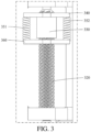
- the embodiments of the present invention disclose an electronic device, including a housing 100, a functional module 200, and a driving mechanism.
- the housing 100 may serve as a main structure of the electronic device, and may provide a mounting base for other components of the electronic device.
- the housing 100 is provided with an opening 110, and the opening 110 allows the functional module 200 to enter and exit the housing 100.
- the housing 100 may include a frame, and the opening 110 may be arranged on the frame.
- the functional module 200 may retract into the housing 100 or extend out of the housing 100 through the opening 110.
- the functional module 200 may include a bracket 210 and a functional device arranged on the bracket 210.
- the functional module 200 may be in a non-working state. In this case, the functional module 200 is hidden in the housing 100.
- the functional module 200 may be in a working state.
- the functional module 200 may retract into the housing 100 through the opening.
- the functional module 200 may not occupy the display area of the electronic device, so that a screen-to-body ratio of the electronic device may be increased.
- the housing 100 does not need to be provided with structures such as a mounting hole corresponding to the functional modules 200, making a better appearance consistency of the electronic device and a better user experience.
- the functional module 200 may include at least one of a camera, a sensor, a fingerprint recognition module, a telephone receiver, and a strobe light.
- the functional module 200 may further include other devices, which are not limited in the embodiments of the present invention.
- the driving mechanism is arranged in the housing 100.
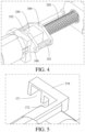
- the driving mechanism includes a driving source 310, a lead screw 320, a nut set, and a caliper 370.
- the driving source 310 is drivingly connected to the lead screw 320.
- the nut set includes a fitting part 330, and the fitting part 330 is threadedly fitted with the lead screw 320.
- a first end of the caliper 370 is in position-limiting fit with the fitting part 330, and a second end of the caliper 370 is fixedly connected to the functional module 200.
- the cross-sectional shape of the fitting part 330 is a polygon.
- the cross-sectional shape of the first end of the caliper 370 may also be a polygon, and the shapes of the two fit in with each other.
- the caliper 370 can limit the rotation of the fitting part 330, making the first end of the caliper 370 be in position-limiting fit with the fitting part 330 more reliably.
- the caliper 370 may fit in with the fitting part 330 in a snap-fit manner, thereby transmitting a force.
- the caliper 370 and the bracket 210 of the functional module 200 are arranged separately, or may be integrally formed. Relatively speaking, when the caliper 370 and the bracket 210 of the functional module 200 are integrally formed, the force may be transmitted more efficiently.
- the foregoing driving source 310 may adopt a driving motor, or may adopt a structure capable of outputting a driving force such as a piezoelectric element as long as the driving source 310 can output the driving force to drive the lead screw 320 to rotate. Therefore, the embodiments of the present invention do not limit the specific form of the driving source 310.
- the driving source 310 may be arranged between the opening 110 and the fitting part 330, making the structure of the driving mechanism more compact.
- the cross-sectional shape of the fitting part 330 may be a triangle, a rectangle, a pentagon, a hexagon, an octagon, or the like.
- the cross-sectional shape of the first end of the caliper 370 may be a triangle, a rectangle, a pentagon, a hexagon, an octagon, or the like.
- the shape of the caliper may fit in with the shape of the fitting part 330, that is, if the shape of the fitting part 330 is a quadrilateral, the shape of the caliper 370 is also a quadrilateral.
- the shape of the caliper 370 may alternatively be different from that of the fitting part 330, but it should be ensured that a position where the fitting part 330 has an edge can fit in with a corresponding edge of the caliper 370, and it is necessary to increase a friction force between the two edges to prevent the two from disengaging from each other.
- the embodiments of the present invention do not limit the cross-sectional shape of the fitting part 330 and the cross-sectional shape of the first end of the caliper 370. It should be noted that the cross-section is parallel to the thickness direction of the electronic device, and is perpendicular to a moving direction of the functional module 200.
- the driving source 310 can drive the lead screw 320 to rotate.
- the lead screw 320 is threadedly fitted with the fitting part 330, and the caliper 370 can limit the rotation of the fitting part 330. Therefore, driven by the lead screw 320, the fitting part 330 can move along the lead screw 320.
- the fitting part 330 can transmit the force to the functional module 200 through the caliper 370. Therefore, the functional module 200 can move relative to the housing 100 under the action of the driving mechanism, and then switch between different states.
- the cross-sectional shape of the fitting part 330 is a polygon. Therefore, the rotation of the fitting part 330 will be limited by the caliper 370, so that the fitting part 330 can drive the caliper 370 to move only along an extension direction of the lead screw 320, but cannot rotate with the lead screw 320. Therefore, the structure can transmit the driving force and limit the rotation of the fitting part 330 through the fit between the caliper 370 and the fitting part 330.
- the electronic device can dispense with specific devices for guiding, making the driving mechanism occupy a smaller space. In addition, the weight of the driving mechanism is reduced, thereby reducing the weight of the electronic device, which is more conducive to a light and thin design of the electronic device.
- the foregoing nut set further includes an elastic member 350 and a movable baffle 360.
- the movable baffle 360 is connected to the fitting part 330 through the elastic member 350, and the movable baffle 360 is located on a side of the fitting part 330 away from the opening 110.
- the caliper 370 is slidable relative to the fitting part 330, and the caliper 370 moves along the lead screw 320. In a case that the caliper 370 is at least partially separated from the fitting part 330, the elastic member 350 drives the movable baffle 360 to make the caliper 370 be in contact with the fitting part 330.
- the caliper 370 may slide relative to the fitting part 330 while limiting the rotation of the fitting part 330, so that a certain movement margin may be generated at a position where the two fit in with each other.
- the lead screw 320 drives the fitting part 330 to move and the fitting part 330 drives the movable baffle 360 to move.
- the caliper 370 is in contact with the movable baffle 360, the movable baffle 360 may drive the caliper 370 to move, thereby driving the functional module 200 to move.
- the external force may be transmitted to the movable baffle 360 through the caliper 370, and the movable baffle 360 moves relative to the fitting part 330.
- the elastic member 350 may be deformed, thereby reducing the movement amount of the fitting part 330, or even preventing the fitting part 330 from moving, to prevent the external force on the functional module 200 from causing damage to the driving mechanism.
- the foregoing elastic member 350 may be a spring, or another elastic part.
- the caliper 370 When the functional module 200 is subjected to the external force, the caliper 370 may be in contact with the movable baffle 360 and drive the movable baffle 360 to move. If the external force on the functional module 200 is relatively large, the movement range of the caliper 370 is relatively large. As a result, the caliper 370 is easily disengaged from the fitting part 330, and a force transmission path between the caliper 370 and the fitting part 330 is cut off. Therefore, to prevent this situation, in an optional embodiment, the electronic device may further include a detection piece 380 and a control piece. The detection piece 380 is arranged in the housing 100.
- the detection piece 380 is triggered and used for detecting a relative distance between the caliper and the fitting part.
- the relative distance may be a distance between the center of gravity of the caliper and the center of gravity of the fitting part, or a distance between a first surface of the caliper and a second surface of the fitting part.
- the first surface of the caliper and the second surface of the fitting part are coplanar.
- the control piece is arranged in the housing 100, and the control piece is electrically connected to the detection piece 380 and the driving source 310 respectively.
- the control piece controls the driving source 310 according to a detection result of the detection piece 380, to cause the driving source 310 to be in a working state.
- the detection piece 380 can be triggered to send a relevant signal.
- the control piece can control the driving source 310 to be in the working state according to the signal, to cause the fitting part 330 to move, so that the fitting part 330 can reliably fit in with the caliper 370.
- the driving source 310 may drive the functional module 200 to retract into the housing 100 through the caliper 370, thereby preventing the functional module 200 from being continuously subjected to the external force, so as to protect the functional module 200.
- the foregoing detection piece 380 may be mounted on the housing 100, and the detection piece 380 is close to the fitting part 330 and the caliper 370, so that a fitting state of the fitting part 330 and the caliper 370 may be accurately learned.
- the detection piece 380 may alternatively be mounted on the fitting part 330, so that the distance between the detection piece 380 and the fitting part 330 and the caliper 370 is smaller, thereby learning the fitting state of the fitting part 330 and the caliper 370 more accurately, and responding to the case that the functional module 200 is subjected to the external force more quickly.
- the foregoing detection piece 380 may adopt a position sensor, a proximity switch, or another device.
- the control piece may be a controller or another device.
- the embodiments of the present invention do not limit specific types of the detection piece 380 and the control piece.
- the movable baffle 360 may be entirely arranged above the lead screw 320.
- the movable baffle 360 is provided with an avoidance hole, and one end of the lead screw 320 passes through the avoidance hole.
- the size of the movable baffle 360 is larger, which can increase a contact area between the movable baffle 360 and the caliper 370, which is conducive to a more reliable transmission of the force between the two, and the movable baffle 360 does not affect the rotation of the lead screw 320.
- the shape of the avoidance hole may fit in with the structure of the lead screw 320.
- the avoidance hole may be a circular hole, and the diameter of the circular hole may be greater than the outer diameter of the lead screw 320, so that a certain gap may be formed between the two.
- the shape may alternatively be a rectangle, a triangle, or the like.
- a plurality of elastic members 350 may be arranged, and include a first elastic member 351 and a second elastic member 352. One end of the first elastic member 351 and one end of the second elastic member 352 are both connected to the movable baffle 360, and the first elastic member 351 and the second elastic member 352 are respectively located on two sides of the lead screw 320. As the number of elastic members 350 increases, the number of connection points between the movable baffle 360 and the fitting part 330 will increase, so that the reliability of the connection between the two is higher and the structure is more stable. In addition, when the functional module 200 is subjected to the external force, a plurality of elastic members 350 may absorb a larger part of the external force, preventing the functional module 200 and the driving mechanism from being damaged.
- the elastic member 350 may be directly connected to one end of the fitting part 330 close to the opening 110.
- the nut set further includes a connecting plate 340.
- the connecting plate 340 is connected to the one end of the fitting part 330 close to the opening 110; and one end of the first elastic member 351 and one end of the second elastic member 352 are both connected to the fitting part 330 through the connecting plate 340.
- the driving source 310 drives the fitting part 330 to move through the lead screw 320, and the connecting plate 340 moves accordingly and drives the caliper 370 to move in a direction away from the opening 110, thereby driving the functional module 200 to move into the housing 100.
- the connecting plate 340 appropriately increased in size can be more reliably connected to the elastic member 350 and the caliper 370, and make it more convenient for an extension direction of the elastic member 350 to be parallel to the moving direction of the functional module 200, thereby making the elastic member 350 transmit the driving force more efficiently and absorb the external force on the functional module 200 better.
- the connecting plate 340 and the fitting part 330 may be arranged separately, that is, the two may be separately formed and then assembled together, or the connecting plate 340 and the fitting part 330 are integrally formed, thereby improving the structural strength of the structure formed by the two.
- the caliper 370 may be provided with a fitting hole.
- the fitting part 330 may fit in with the fitting hole.
- the caliper 370 is provided with a linkage recess 371.
- the linkage recess 371 is in position-limiting fit with the fitting part 330.
- the linkage recess 371 may first pass through the caliper 370 in a moving direction of the functional module 200, and may further extend to a surface of the caliper 370 in a direction perpendicular to the moving direction.
- the structure of the linkage recess 371 is similar to that of a groove. Relatively speaking, the linkage recess 371 has fewer limitations on an assembling direction of the caliper 370, so it is convenient to assemble the caliper 370 and the driving mechanism, making the assembly efficiency of the electronic device higher.
- the electronic device disclosed in the embodiments of the present invention may be a smartphone, a tablet computer, an e-book reader, a wearable device (such as a smart watch), a video game console, or another device.
- the embodiments of the present invention do not limit a specific type of the electronic device.
Landscapes
- Engineering & Computer Science (AREA)
- Signal Processing (AREA)
- Computer Hardware Design (AREA)
- Theoretical Computer Science (AREA)
- General Physics & Mathematics (AREA)
- General Engineering & Computer Science (AREA)
- Physics & Mathematics (AREA)
- Human Computer Interaction (AREA)
- Multimedia (AREA)
- Transmission Devices (AREA)
- Braking Arrangements (AREA)
- Accessories Of Cameras (AREA)
- Mounting Components In General For Electric Apparatus (AREA)
- Casings For Electric Apparatus (AREA)
- Fittings On The Vehicle Exterior For Carrying Loads, And Devices For Holding Or Mounting Articles (AREA)
Claims (9)
- Elektronische Vorrichtung, umfassend:eine Aufnahme (100), wobei die Aufnahme (100) mit einer Öffnung (110) versehen ist;ein Funktionsmodul (200), wobei das Funktionsmodul (200) durch die Öffnung (110) in die Aufnahme (100) eingefahren oder aus der Aufnahme (100) ausgefahren werden kann, und einen Antriebsmechanismus, wobei der Antriebsmechanismus in der Aufnahme (100) angeordnet ist und der Antriebsmechanismus eine Antriebsquelle (310), eine Leitspindel (320) und einen Muttersatz sowie einen Messschieber (370) umfasst, wobei die Antriebsquelle (310) antriebsmäßig mit der Leitspindel (320) verbunden ist, der Muttersatz einen Anbringungsteil (330) umfasst und der Anbringungsteil (330) mittels eines Gewindes an der Leitspindel (320) angebracht ist, sich ein erstes Ende des Messschiebers (370) in positionsbegrenzender Anbringung mit dem Anbringungsteil (330) befindet und ein zweites Ende des Messschiebers (370) fix mit dem Funktionsmodul (200) verbunden ist und die Querschnittsform des Anbringungsteils (330) ein Vieleck ist,dadurch gekennzeichnet, dass der Muttersatz zudem ein elastisches Element (350) und ein bewegbares Leitblech (360) umfasst, das bewegbare Leitblech (360) mit dem Anbringungsteil (330) durch das elastische Element (350) verbunden ist und das bewegbare Leitblech (360) auf einer Seite des Anbringungsteils (330) entfernt von der Öffnung (110) befindlich ist, der Messschieber (370) relativ zum Anbringungsteil (330) verschiebbar ist und sich der Messschieber (370) entlang der Leitspindel (320) bewegt, wobei das elastische Element (350) das bewegbare Leitblech (360) antreibt, sodass der Kontakt zwischen dem Messschieber (370) und dem Anbringungsteil (330) hergestellt wird, wenn der Messchieber (370) mindestens teilweise getrennt vom Anbringungsteil (330) angeordnet ist.
- Elektronische Vorrichtung nach Anspruch 1, wobei die elektronische Vorrichtung zudem Folgendes umfasst:ein Detektionsstück (380), wobei das Detektionsstück (380) in der Aufnahme (100) angeordnet ist, das Detektionsstück (380) einen relativen Abstand zwischen dem Messschieber (370) und dem Anbringungsteil (330) detektiert, wenn der Messschieber (370) mindestens teilweise vom Anbringungsteil (330) getrennt angeordnet ist, undein Steuerungsstück, wobei das Steuerungsstück in der Aufnahme (100) angeordnet ist und das Steuerungsstück elektrisch jeweils mit dem Detektionsstück (380) und der Antriebsquelle (310) verbunden ist und das Steuerungsstück die Antriebsquelle (310) je nach einem Detektionsergebnis des Detektionsstücks (380) steuert.
- Elektronische Vorrichtung nach Anspruch 2, wobei das Detektionsstück (380) auf dem Anbringungsteil (330) montiert ist.
- Elektronische Vorrichtung nach Anspruch 1, wobei das bewegbare Leitblech (360) mit einem Umgehungsloch versehen ist und ein Ende der Leitspindel (320) durch das Umgehungsloch führt.
- Elektrische Vorrichtung nach Anspruch 1, wobei eine Vielzahl von elastischen Elementen (350) angeordnet ist und ein erstes elastisches Element (351) und ein zweites elastisches Element (352) umfasst, ein Ende des ersten elastischen Elements (351) und ein Ende des zweiten elastischen Elements (352) beide mit dem bewegbaren Leitblech (360) verbunden sind und das erste elastische Element (351) und das zweite elastische Element (352) jeweils auf zwei Seiten der Leitspindel (320) befindlich sind.
- Elektronische Vorrichtung nach Anspruch 5, wobei der Muttersatz zudem eine Verbindungsplatte (340) umfasst, die Verbindungsplatte (340) mit einem Ende des Anbringungsteils (330) in der Nähe der Öffnung (110) verbunden ist und ein Ende des ersten elastischen Elements (351) und ein Ende des zweiten elastischen Elements (352) beide mit dem Anbringungsteil (330) durch die Verbindungsplatte (340) verbunden sind.
- Elektronische Vorrichtung nach Anspruch 1, wobei der Messschieber (370) mit einer Umgehungsausnehmung (372) versehen ist und mindestens ein Teil des elastischen Elements (350) in der Umgehungsausnehmung (372) befindlich ist.
- Elektronische Vorrichtung nach Anspruch 1, wobei der Messschieber (370) mit einer Kopplungsausnehmung (371) versehen ist und sich die Kopplungsausnehmung (371) in einer positionsbegrenzenden Anbringung mit dem Anbringungsteil (330) befindet.
- Elektronische Vorrichtung nach Anspruch 1, wobei das Funktionsmodul (200) mindestens eine Kammer und/oder einen Sensor und/oder ein Fingerabdruckerkennungsmodul, einen Telefonempfänger und/oder ein Stroboskoplicht umfasst.
Applications Claiming Priority (2)
| Application Number | Priority Date | Filing Date | Title |
|---|---|---|---|
| CN202010241344.7A CN111416897B (zh) | 2020-03-30 | 2020-03-30 | 电子设备 |
| PCT/CN2021/075396 WO2021196887A1 (zh) | 2020-03-30 | 2021-02-05 | 电子设备 |
Publications (3)
| Publication Number | Publication Date |
|---|---|
| EP4131899A1 EP4131899A1 (de) | 2023-02-08 |
| EP4131899A4 EP4131899A4 (de) | 2023-10-11 |
| EP4131899B1 true EP4131899B1 (de) | 2024-10-23 |
Family
ID=71494729
Family Applications (1)
| Application Number | Title | Priority Date | Filing Date |
|---|---|---|---|
| EP21782202.2A Active EP4131899B1 (de) | 2020-03-30 | 2021-02-05 | Elektronische vorrichtung |
Country Status (7)
| Country | Link |
|---|---|
| US (1) | US12284302B2 (de) |
| EP (1) | EP4131899B1 (de) |
| JP (1) | JP7478247B2 (de) |
| KR (1) | KR102701174B1 (de) |
| CN (1) | CN111416897B (de) |
| ES (1) | ES2993676T3 (de) |
| WO (1) | WO2021196887A1 (de) |
Families Citing this family (2)
| Publication number | Priority date | Publication date | Assignee | Title |
|---|---|---|---|---|
| CN111416897B (zh) * | 2020-03-30 | 2021-04-23 | 维沃移动通信有限公司 | 电子设备 |
| CN111880609B (zh) * | 2020-07-31 | 2023-02-21 | 维沃移动通信有限公司 | 电子设备 |
Family Cites Families (20)
| Publication number | Priority date | Publication date | Assignee | Title |
|---|---|---|---|---|
| KR101003259B1 (ko) * | 2003-08-02 | 2010-12-21 | 엘지전자 주식회사 | 줌기능 카메라모듈 및 이를 구비한 이동단말기 |
| JP2014215507A (ja) | 2013-04-26 | 2014-11-17 | 株式会社ザクティ | 撮像装置 |
| CN107197133B (zh) * | 2017-07-21 | 2019-11-29 | 维沃移动通信有限公司 | 一种移动终端及摄像头组件 |
| EP3477922B1 (de) | 2017-10-31 | 2020-11-04 | Guangdong Oppo Mobile Telecommunications Corp., Ltd. | Funktionelle vorrichtung und mobiles endgerät |
| CN109862222B (zh) | 2017-11-30 | 2021-04-27 | Oppo广东移动通信有限公司 | 一种摄像头组件、移动终端及其摄像头组件的控制方法 |
| CN109862237B (zh) * | 2017-11-30 | 2021-04-27 | Oppo广东移动通信有限公司 | 一种摄像头组件、移动终端及其摄像头组件的控制方法 |
| CN109862224B (zh) * | 2017-11-30 | 2021-04-27 | Oppo广东移动通信有限公司 | 一种摄像头组件、移动终端及其摄像头组件的控制方法 |
| CN109951588B (zh) * | 2017-12-20 | 2021-03-05 | Oppo广东移动通信有限公司 | 功能组件、电子装置及电子装置的控制方法 |
| CN110072038B (zh) * | 2018-01-24 | 2020-06-12 | Oppo广东移动通信有限公司 | 摄像头组件以及电子设备 |
| CN110319167B (zh) * | 2018-03-31 | 2021-09-17 | Oppo广东移动通信有限公司 | 驱动组件、电子装置及电子装置的控制方法 |
| CN110324447B (zh) | 2018-03-31 | 2021-05-28 | Oppo广东移动通信有限公司 | 电子装置和电子装置的控制方法 |
| CN208624022U (zh) * | 2018-08-15 | 2019-03-19 | 华硕电脑股份有限公司 | 电子装置 |
| CN209419667U (zh) | 2018-12-26 | 2019-09-20 | Oppo广东移动通信有限公司 | 电子装置 |
| CN109973767A (zh) * | 2019-03-27 | 2019-07-05 | 领先科技(东台)有限公司 | 一种可分离式升降摄像头 |
| CN209839539U (zh) * | 2019-03-27 | 2019-12-24 | 领先科技(东台)有限公司 | 一种可分离式升降摄像头 |
| CN110113455B (zh) | 2019-04-29 | 2021-08-13 | 荣耀终端有限公司 | 位置检测机构、移动终端及位置检测方法 |
| CN110557482B (zh) | 2019-08-29 | 2021-06-11 | 维沃移动通信(杭州)有限公司 | 电子设备 |
| CN110839125B (zh) * | 2019-11-20 | 2021-02-19 | 诚瑞光学(常州)股份有限公司 | 电子设备及电子设备的使用方法 |
| CN110730294B (zh) * | 2019-11-22 | 2021-02-19 | 诚瑞光学(常州)股份有限公司 | 摄像头系统及移动终端 |
| CN111416897B (zh) * | 2020-03-30 | 2021-04-23 | 维沃移动通信有限公司 | 电子设备 |
-
2020
- 2020-03-30 CN CN202010241344.7A patent/CN111416897B/zh active Active
-
2021
- 2021-02-05 EP EP21782202.2A patent/EP4131899B1/de active Active
- 2021-02-05 WO PCT/CN2021/075396 patent/WO2021196887A1/zh not_active Ceased
- 2021-02-05 ES ES21782202T patent/ES2993676T3/es active Active
- 2021-02-05 JP JP2022559309A patent/JP7478247B2/ja active Active
- 2021-02-05 KR KR1020227036831A patent/KR102701174B1/ko active Active
-
2022
- 2022-09-21 US US17/949,523 patent/US12284302B2/en active Active
Also Published As
| Publication number | Publication date |
|---|---|
| CN111416897A (zh) | 2020-07-14 |
| KR20220157479A (ko) | 2022-11-29 |
| WO2021196887A1 (zh) | 2021-10-07 |
| EP4131899A1 (de) | 2023-02-08 |
| US20230016833A1 (en) | 2023-01-19 |
| CN111416897B (zh) | 2021-04-23 |
| JP7478247B2 (ja) | 2024-05-02 |
| EP4131899A4 (de) | 2023-10-11 |
| KR102701174B1 (ko) | 2024-08-29 |
| JP2023519929A (ja) | 2023-05-15 |
| US12284302B2 (en) | 2025-04-22 |
| ES2993676T3 (en) | 2025-01-03 |
Similar Documents
| Publication | Publication Date | Title |
|---|---|---|
| US11796894B2 (en) | Optical element driving mechanism | |
| EP3454542B1 (de) | Kameramodul und elektronische vorrichtung | |
| US12284302B2 (en) | Electronic device | |
| CN109803082B (zh) | 移动终端 | |
| CN207638754U (zh) | 摄像头组件及电子设备 | |
| WO2020216186A1 (zh) | 终端设备 | |
| EP4131897B1 (de) | Elektronische vorrichtung | |
| US20190124187A1 (en) | Ejection assembly, mobile terminal, and electronic device | |
| WO2020199922A1 (zh) | 终端设备 | |
| US12342063B2 (en) | Camera module and electronic device including a protection structural member, a gimbal camera and a support seat | |
| US11876919B2 (en) | Terminal device | |
| WO2020177562A1 (zh) | 终端设备 | |
| CN110087428B (zh) | 移动终端 | |
| CN207782889U (zh) | 驱动装置移动终端 | |
| CN110336900A (zh) | 摄像头模组及移动终端 | |
| WO2021143761A1 (zh) | 运动结构、开合装置及移动终端 | |
| WO2020221352A1 (zh) | 终端设备 | |
| CN210297792U (zh) | 电子设备 | |
| CN111629089B (zh) | 电子设备 | |
| CN111459229A (zh) | 伸缩模组以及电子设备 | |
| WO2020098628A1 (zh) | 移动终端 | |
| CN109962995A (zh) | 功能组件、电子装置及其控制方法 | |
| CN111050044A (zh) | 电子设备 | |
| KR20250100441A (ko) | 랙 기어 가이드 구조를 포함하는 전자 장치 | |
| KR20260027647A (ko) | 구동 모터를 포함하는 전자 장치 |
Legal Events
| Date | Code | Title | Description |
|---|---|---|---|
| STAA | Information on the status of an ep patent application or granted ep patent |
Free format text: STATUS: THE INTERNATIONAL PUBLICATION HAS BEEN MADE |
|
| PUAI | Public reference made under article 153(3) epc to a published international application that has entered the european phase |
Free format text: ORIGINAL CODE: 0009012 |
|
| STAA | Information on the status of an ep patent application or granted ep patent |
Free format text: STATUS: REQUEST FOR EXAMINATION WAS MADE |
|
| 17P | Request for examination filed |
Effective date: 20220921 |
|
| AK | Designated contracting states |
Kind code of ref document: A1 Designated state(s): AL AT BE BG CH CY CZ DE DK EE ES FI FR GB GR HR HU IE IS IT LI LT LU LV MC MK MT NL NO PL PT RO RS SE SI SK SM TR |
|
| DAV | Request for validation of the european patent (deleted) | ||
| DAX | Request for extension of the european patent (deleted) | ||
| A4 | Supplementary search report drawn up and despatched |
Effective date: 20230908 |
|
| RIC1 | Information provided on ipc code assigned before grant |
Ipc: H04N 23/57 20230101ALI20230904BHEP Ipc: H04N 23/50 20230101ALI20230904BHEP Ipc: G06F 1/16 20060101ALI20230904BHEP Ipc: H04M 1/02 20060101AFI20230904BHEP |
|
| GRAP | Despatch of communication of intention to grant a patent |
Free format text: ORIGINAL CODE: EPIDOSNIGR1 |
|
| STAA | Information on the status of an ep patent application or granted ep patent |
Free format text: STATUS: GRANT OF PATENT IS INTENDED |
|
| RIC1 | Information provided on ipc code assigned before grant |
Ipc: H04N 23/57 20230101ALI20240621BHEP Ipc: H04N 23/50 20230101ALI20240621BHEP Ipc: G06F 1/16 20060101ALI20240621BHEP Ipc: H04M 1/02 20060101AFI20240621BHEP |
|
| INTG | Intention to grant announced |
Effective date: 20240708 |
|
| GRAS | Grant fee paid |
Free format text: ORIGINAL CODE: EPIDOSNIGR3 |
|
| GRAA | (expected) grant |
Free format text: ORIGINAL CODE: 0009210 |
|
| STAA | Information on the status of an ep patent application or granted ep patent |
Free format text: STATUS: THE PATENT HAS BEEN GRANTED |
|
| AK | Designated contracting states |
Kind code of ref document: B1 Designated state(s): AL AT BE BG CH CY CZ DE DK EE ES FI FR GB GR HR HU IE IS IT LI LT LU LV MC MK MT NL NO PL PT RO RS SE SI SK SM TR |
|
| REG | Reference to a national code |
Ref country code: GB Ref legal event code: FG4D |
|
| REG | Reference to a national code |
Ref country code: CH Ref legal event code: EP |
|
| REG | Reference to a national code |
Ref country code: DE Ref legal event code: R096 Ref document number: 602021020725 Country of ref document: DE |
|
| REG | Reference to a national code |
Ref country code: NL Ref legal event code: FP Ref country code: IE Ref legal event code: FG4D |
|
| REG | Reference to a national code |
Ref country code: ES Ref legal event code: FG2A Ref document number: 2993676 Country of ref document: ES Kind code of ref document: T3 Effective date: 20250103 |
|
| REG | Reference to a national code |
Ref country code: LT Ref legal event code: MG9D |
|
| REG | Reference to a national code |
Ref country code: AT Ref legal event code: MK05 Ref document number: 1735789 Country of ref document: AT Kind code of ref document: T Effective date: 20241023 |
|
| PG25 | Lapsed in a contracting state [announced via postgrant information from national office to epo] |
Ref country code: IS Free format text: LAPSE BECAUSE OF FAILURE TO SUBMIT A TRANSLATION OF THE DESCRIPTION OR TO PAY THE FEE WITHIN THE PRESCRIBED TIME-LIMIT Effective date: 20250223 Ref country code: PT Free format text: LAPSE BECAUSE OF FAILURE TO SUBMIT A TRANSLATION OF THE DESCRIPTION OR TO PAY THE FEE WITHIN THE PRESCRIBED TIME-LIMIT Effective date: 20250224 Ref country code: HR Free format text: LAPSE BECAUSE OF FAILURE TO SUBMIT A TRANSLATION OF THE DESCRIPTION OR TO PAY THE FEE WITHIN THE PRESCRIBED TIME-LIMIT Effective date: 20241023 |
|
| PG25 | Lapsed in a contracting state [announced via postgrant information from national office to epo] |
Ref country code: FI Free format text: LAPSE BECAUSE OF FAILURE TO SUBMIT A TRANSLATION OF THE DESCRIPTION OR TO PAY THE FEE WITHIN THE PRESCRIBED TIME-LIMIT Effective date: 20241023 |
|
| PG25 | Lapsed in a contracting state [announced via postgrant information from national office to epo] |
Ref country code: BG Free format text: LAPSE BECAUSE OF FAILURE TO SUBMIT A TRANSLATION OF THE DESCRIPTION OR TO PAY THE FEE WITHIN THE PRESCRIBED TIME-LIMIT Effective date: 20241023 |
|
| PG25 | Lapsed in a contracting state [announced via postgrant information from national office to epo] |
Ref country code: NO Free format text: LAPSE BECAUSE OF FAILURE TO SUBMIT A TRANSLATION OF THE DESCRIPTION OR TO PAY THE FEE WITHIN THE PRESCRIBED TIME-LIMIT Effective date: 20250123 |
|
| PG25 | Lapsed in a contracting state [announced via postgrant information from national office to epo] |
Ref country code: AT Free format text: LAPSE BECAUSE OF FAILURE TO SUBMIT A TRANSLATION OF THE DESCRIPTION OR TO PAY THE FEE WITHIN THE PRESCRIBED TIME-LIMIT Effective date: 20241023 Ref country code: LV Free format text: LAPSE BECAUSE OF FAILURE TO SUBMIT A TRANSLATION OF THE DESCRIPTION OR TO PAY THE FEE WITHIN THE PRESCRIBED TIME-LIMIT Effective date: 20241023 Ref country code: GR Free format text: LAPSE BECAUSE OF FAILURE TO SUBMIT A TRANSLATION OF THE DESCRIPTION OR TO PAY THE FEE WITHIN THE PRESCRIBED TIME-LIMIT Effective date: 20250124 |
|
| PG25 | Lapsed in a contracting state [announced via postgrant information from national office to epo] |
Ref country code: PL Free format text: LAPSE BECAUSE OF FAILURE TO SUBMIT A TRANSLATION OF THE DESCRIPTION OR TO PAY THE FEE WITHIN THE PRESCRIBED TIME-LIMIT Effective date: 20241023 |
|
| PG25 | Lapsed in a contracting state [announced via postgrant information from national office to epo] |
Ref country code: RS Free format text: LAPSE BECAUSE OF FAILURE TO SUBMIT A TRANSLATION OF THE DESCRIPTION OR TO PAY THE FEE WITHIN THE PRESCRIBED TIME-LIMIT Effective date: 20250123 |
|
| PG25 | Lapsed in a contracting state [announced via postgrant information from national office to epo] |
Ref country code: SM Free format text: LAPSE BECAUSE OF FAILURE TO SUBMIT A TRANSLATION OF THE DESCRIPTION OR TO PAY THE FEE WITHIN THE PRESCRIBED TIME-LIMIT Effective date: 20241023 |
|
| PG25 | Lapsed in a contracting state [announced via postgrant information from national office to epo] |
Ref country code: DK Free format text: LAPSE BECAUSE OF FAILURE TO SUBMIT A TRANSLATION OF THE DESCRIPTION OR TO PAY THE FEE WITHIN THE PRESCRIBED TIME-LIMIT Effective date: 20241023 |
|
| PG25 | Lapsed in a contracting state [announced via postgrant information from national office to epo] |
Ref country code: EE Free format text: LAPSE BECAUSE OF FAILURE TO SUBMIT A TRANSLATION OF THE DESCRIPTION OR TO PAY THE FEE WITHIN THE PRESCRIBED TIME-LIMIT Effective date: 20241023 |
|
| PG25 | Lapsed in a contracting state [announced via postgrant information from national office to epo] |
Ref country code: RO Free format text: LAPSE BECAUSE OF FAILURE TO SUBMIT A TRANSLATION OF THE DESCRIPTION OR TO PAY THE FEE WITHIN THE PRESCRIBED TIME-LIMIT Effective date: 20241023 |
|
| REG | Reference to a national code |
Ref country code: DE Ref legal event code: R097 Ref document number: 602021020725 Country of ref document: DE |
|
| PG25 | Lapsed in a contracting state [announced via postgrant information from national office to epo] |
Ref country code: SK Free format text: LAPSE BECAUSE OF FAILURE TO SUBMIT A TRANSLATION OF THE DESCRIPTION OR TO PAY THE FEE WITHIN THE PRESCRIBED TIME-LIMIT Effective date: 20241023 |
|
| PG25 | Lapsed in a contracting state [announced via postgrant information from national office to epo] |
Ref country code: CZ Free format text: LAPSE BECAUSE OF FAILURE TO SUBMIT A TRANSLATION OF THE DESCRIPTION OR TO PAY THE FEE WITHIN THE PRESCRIBED TIME-LIMIT Effective date: 20241023 |
|
| PLBE | No opposition filed within time limit |
Free format text: ORIGINAL CODE: 0009261 |
|
| STAA | Information on the status of an ep patent application or granted ep patent |
Free format text: STATUS: NO OPPOSITION FILED WITHIN TIME LIMIT |
|
| PG25 | Lapsed in a contracting state [announced via postgrant information from national office to epo] |
Ref country code: SE Free format text: LAPSE BECAUSE OF FAILURE TO SUBMIT A TRANSLATION OF THE DESCRIPTION OR TO PAY THE FEE WITHIN THE PRESCRIBED TIME-LIMIT Effective date: 20241023 |
|
| PG25 | Lapsed in a contracting state [announced via postgrant information from national office to epo] |
Ref country code: MC Free format text: LAPSE BECAUSE OF FAILURE TO SUBMIT A TRANSLATION OF THE DESCRIPTION OR TO PAY THE FEE WITHIN THE PRESCRIBED TIME-LIMIT Effective date: 20241023 |
|
| REG | Reference to a national code |
Ref country code: CH Ref legal event code: PL |
|
| 26N | No opposition filed |
Effective date: 20250724 |
|
| PG25 | Lapsed in a contracting state [announced via postgrant information from national office to epo] |
Ref country code: LU Free format text: LAPSE BECAUSE OF NON-PAYMENT OF DUE FEES Effective date: 20250205 |
|
| PG25 | Lapsed in a contracting state [announced via postgrant information from national office to epo] |
Ref country code: CH Free format text: LAPSE BECAUSE OF NON-PAYMENT OF DUE FEES Effective date: 20250228 |
|
| REG | Reference to a national code |
Ref country code: BE Ref legal event code: MM Effective date: 20250228 |
|
| PGFP | Annual fee paid to national office [announced via postgrant information from national office to epo] |
Ref country code: FR Payment date: 20251231 Year of fee payment: 6 |
|
| PG25 | Lapsed in a contracting state [announced via postgrant information from national office to epo] |
Ref country code: BE Free format text: LAPSE BECAUSE OF NON-PAYMENT OF DUE FEES Effective date: 20250228 |
|
| PG25 | Lapsed in a contracting state [announced via postgrant information from national office to epo] |
Ref country code: IE Free format text: LAPSE BECAUSE OF NON-PAYMENT OF DUE FEES Effective date: 20250205 |
|
| PGFP | Annual fee paid to national office [announced via postgrant information from national office to epo] |
Ref country code: NL Payment date: 20260106 Year of fee payment: 6 |
|
| PGFP | Annual fee paid to national office [announced via postgrant information from national office to epo] |
Ref country code: GB Payment date: 20260106 Year of fee payment: 6 |
|
| PGFP | Annual fee paid to national office [announced via postgrant information from national office to epo] |
Ref country code: ES Payment date: 20260310 Year of fee payment: 6 |
|
| PGFP | Annual fee paid to national office [announced via postgrant information from national office to epo] |
Ref country code: DE Payment date: 20251230 Year of fee payment: 6 |
|
| PGFP | Annual fee paid to national office [announced via postgrant information from national office to epo] |
Ref country code: IT Payment date: 20260122 Year of fee payment: 6 |