EP4131573B1 - Batteriediagnosevorrichtung und -verfahren - Google Patents
Batteriediagnosevorrichtung und -verfahren Download PDFInfo
- Publication number
- EP4131573B1 EP4131573B1 EP21880484.7A EP21880484A EP4131573B1 EP 4131573 B1 EP4131573 B1 EP 4131573B1 EP 21880484 A EP21880484 A EP 21880484A EP 4131573 B1 EP4131573 B1 EP 4131573B1
- Authority
- EP
- European Patent Office
- Prior art keywords
- battery
- change rate
- internal gas
- criterion
- control unit
- Prior art date
- Legal status (The legal status is an assumption and is not a legal conclusion. Google has not performed a legal analysis and makes no representation as to the accuracy of the status listed.)
- Active
Links
Images

Classifications
-
- G—PHYSICS
- G01—MEASURING; TESTING
- G01R—MEASURING ELECTRIC VARIABLES; MEASURING MAGNETIC VARIABLES
- G01R31/00—Arrangements for testing electric properties; Arrangements for locating electric faults; Arrangements for electrical testing characterised by what is being tested not provided for elsewhere
- G01R31/36—Arrangements for testing, measuring or monitoring the electrical condition of accumulators or electric batteries, e.g. capacity or state of charge [SoC]
- G01R31/3644—Constructional arrangements
- G01R31/3646—Constructional arrangements for indicating electrical conditions or variables, e.g. visual or audible indicators
-
- G—PHYSICS
- G01—MEASURING; TESTING
- G01R—MEASURING ELECTRIC VARIABLES; MEASURING MAGNETIC VARIABLES
- G01R31/00—Arrangements for testing electric properties; Arrangements for locating electric faults; Arrangements for electrical testing characterised by what is being tested not provided for elsewhere
- G01R31/36—Arrangements for testing, measuring or monitoring the electrical condition of accumulators or electric batteries, e.g. capacity or state of charge [SoC]
- G01R31/382—Arrangements for monitoring battery or accumulator variables, e.g. SoC
-
- G—PHYSICS
- G01—MEASURING; TESTING
- G01R—MEASURING ELECTRIC VARIABLES; MEASURING MAGNETIC VARIABLES
- G01R31/00—Arrangements for testing electric properties; Arrangements for locating electric faults; Arrangements for electrical testing characterised by what is being tested not provided for elsewhere
- G01R31/36—Arrangements for testing, measuring or monitoring the electrical condition of accumulators or electric batteries, e.g. capacity or state of charge [SoC]
- G01R31/385—Arrangements for measuring battery or accumulator variables
- G01R31/387—Determining ampere-hour charge capacity or SoC
-
- G—PHYSICS
- G01—MEASURING; TESTING
- G01R—MEASURING ELECTRIC VARIABLES; MEASURING MAGNETIC VARIABLES
- G01R31/00—Arrangements for testing electric properties; Arrangements for locating electric faults; Arrangements for electrical testing characterised by what is being tested not provided for elsewhere
- G01R31/36—Arrangements for testing, measuring or monitoring the electrical condition of accumulators or electric batteries, e.g. capacity or state of charge [SoC]
- G01R31/389—Measuring internal impedance, internal conductance or related variables
-
- G—PHYSICS
- G01—MEASURING; TESTING
- G01R—MEASURING ELECTRIC VARIABLES; MEASURING MAGNETIC VARIABLES
- G01R31/00—Arrangements for testing electric properties; Arrangements for locating electric faults; Arrangements for electrical testing characterised by what is being tested not provided for elsewhere
- G01R31/36—Arrangements for testing, measuring or monitoring the electrical condition of accumulators or electric batteries, e.g. capacity or state of charge [SoC]
- G01R31/392—Determining battery ageing or deterioration, e.g. state of health
-
- H—ELECTRICITY
- H01—ELECTRIC ELEMENTS
- H01M—PROCESSES OR MEANS, e.g. BATTERIES, FOR THE DIRECT CONVERSION OF CHEMICAL ENERGY INTO ELECTRICAL ENERGY
- H01M10/00—Secondary cells; Manufacture thereof
- H01M10/42—Methods or arrangements for servicing or maintenance of secondary cells or secondary half-cells
- H01M10/425—Structural combination with electronic components, e.g. electronic circuits integrated to the outside of the casing
-
- H—ELECTRICITY
- H01—ELECTRIC ELEMENTS
- H01M—PROCESSES OR MEANS, e.g. BATTERIES, FOR THE DIRECT CONVERSION OF CHEMICAL ENERGY INTO ELECTRICAL ENERGY
- H01M10/00—Secondary cells; Manufacture thereof
- H01M10/42—Methods or arrangements for servicing or maintenance of secondary cells or secondary half-cells
- H01M10/44—Methods for charging or discharging
- H01M10/443—Methods for charging or discharging in response to temperature
-
- H—ELECTRICITY
- H01—ELECTRIC ELEMENTS
- H01M—PROCESSES OR MEANS, e.g. BATTERIES, FOR THE DIRECT CONVERSION OF CHEMICAL ENERGY INTO ELECTRICAL ENERGY
- H01M10/00—Secondary cells; Manufacture thereof
- H01M10/42—Methods or arrangements for servicing or maintenance of secondary cells or secondary half-cells
- H01M10/48—Accumulators combined with arrangements for measuring, testing or indicating the condition of cells, e.g. the level or density of the electrolyte
- H01M10/486—Accumulators combined with arrangements for measuring, testing or indicating the condition of cells, e.g. the level or density of the electrolyte for measuring temperature
-
- H—ELECTRICITY
- H01—ELECTRIC ELEMENTS
- H01M—PROCESSES OR MEANS, e.g. BATTERIES, FOR THE DIRECT CONVERSION OF CHEMICAL ENERGY INTO ELECTRICAL ENERGY
- H01M10/00—Secondary cells; Manufacture thereof
- H01M10/60—Heating or cooling; Temperature control
- H01M10/61—Types of temperature control
- H01M10/615—Heating or keeping warm
-
- H—ELECTRICITY
- H02—GENERATION; CONVERSION OR DISTRIBUTION OF ELECTRIC POWER
- H02J—CIRCUIT ARRANGEMENTS OR SYSTEMS FOR SUPPLYING OR DISTRIBUTING ELECTRIC POWER; SYSTEMS FOR STORING ELECTRIC ENERGY
- H02J7/00—Circuit arrangements for charging or depolarising batteries or for supplying loads from batteries
- H02J7/0047—Circuit arrangements for charging or depolarising batteries or for supplying loads from batteries with monitoring or indicating devices or circuits
- H02J7/0048—Detection of remaining charge capacity or state of charge [SOC]
-
- H—ELECTRICITY
- H02—GENERATION; CONVERSION OR DISTRIBUTION OF ELECTRIC POWER
- H02J—CIRCUIT ARRANGEMENTS OR SYSTEMS FOR SUPPLYING OR DISTRIBUTING ELECTRIC POWER; SYSTEMS FOR STORING ELECTRIC ENERGY
- H02J7/00—Circuit arrangements for charging or depolarising batteries or for supplying loads from batteries
- H02J7/0047—Circuit arrangements for charging or depolarising batteries or for supplying loads from batteries with monitoring or indicating devices or circuits
- H02J7/005—Detection of state of health [SOH]
-
- G—PHYSICS
- G01—MEASURING; TESTING
- G01R—MEASURING ELECTRIC VARIABLES; MEASURING MAGNETIC VARIABLES
- G01R31/00—Arrangements for testing electric properties; Arrangements for locating electric faults; Arrangements for electrical testing characterised by what is being tested not provided for elsewhere
- G01R31/36—Arrangements for testing, measuring or monitoring the electrical condition of accumulators or electric batteries, e.g. capacity or state of charge [SoC]
- G01R31/385—Arrangements for measuring battery or accumulator variables
- G01R31/387—Determining ampere-hour charge capacity or SoC
- G01R31/388—Determining ampere-hour charge capacity or SoC involving voltage measurements
-
- H—ELECTRICITY
- H01—ELECTRIC ELEMENTS
- H01M—PROCESSES OR MEANS, e.g. BATTERIES, FOR THE DIRECT CONVERSION OF CHEMICAL ENERGY INTO ELECTRICAL ENERGY
- H01M10/00—Secondary cells; Manufacture thereof
- H01M10/42—Methods or arrangements for servicing or maintenance of secondary cells or secondary half-cells
- H01M10/425—Structural combination with electronic components, e.g. electronic circuits integrated to the outside of the casing
- H01M2010/4271—Battery management systems including electronic circuits, e.g. control of current or voltage to keep battery in healthy state, cell balancing
-
- Y—GENERAL TAGGING OF NEW TECHNOLOGICAL DEVELOPMENTS; GENERAL TAGGING OF CROSS-SECTIONAL TECHNOLOGIES SPANNING OVER SEVERAL SECTIONS OF THE IPC; TECHNICAL SUBJECTS COVERED BY FORMER USPC CROSS-REFERENCE ART COLLECTIONS [XRACs] AND DIGESTS
- Y02—TECHNOLOGIES OR APPLICATIONS FOR MITIGATION OR ADAPTATION AGAINST CLIMATE CHANGE
- Y02E—REDUCTION OF GREENHOUSE GAS [GHG] EMISSIONS, RELATED TO ENERGY GENERATION, TRANSMISSION OR DISTRIBUTION
- Y02E60/00—Enabling technologies; Technologies with a potential or indirect contribution to GHG emissions mitigation
- Y02E60/10—Energy storage using batteries
Definitions
- the present disclosure relates to a battery diagnosing apparatus and method, and more particularly, to a battery diagnosing apparatus and method capable of diagnosing an internal gas generation level and an internal gas generation cause of a battery.
- Batteries commercially available at present include nickel-cadmium batteries, nickel hydrogen batteries, nickel-zinc batteries, lithium batteries and the like.
- the lithium batteries are in the limelight since they have almost no memory effect compared to nickel-based batteries and also have very low self-charging rate and high energy density.
- US 2017/123013 A1 describes a post-deterioration performance estimating apparatus indicating performance of an energy storage device.
- a post-deterioration performance estimator is configured to electronically estimate the post-deterioration performance value at a deterioration point using a relation between a cumulative operating period and a resistance value, a relation between the resistance value and energy storage capacity, and the cumulative operating period at the deterioration point.
- the post-deterioration performance estimator is configured to electronically estimate the post-deterioration performance value at a deterioration point using a relation between an equilibrial capacity decreased amount, a kinetic capacity decreased amount, and a cumulative operating period at the deterioration point.
- the present disclosure is designed to solve the problems of the related art, and therefore the present disclosure is directed to providing a battery diagnosing apparatus and method for diagnosing an internal gas generation level and an internal gas generation cause of a battery in a non-destructive manner based on an impedance profile of the battery.
- a battery diagnosing apparatus may comprise: a measuring unit configured to measure discharge capacity and temperature of a battery; an ohmic resistance determining unit configured to determine an ohmic resistance of the battery based on an impedance profile generated for the battery; and a control unit configured to calculate a capacity change rate by comparing the discharge capacity of the battery measured by the measuring unit with a reference capacity, calculate a resistance change rate by comparing the ohmic resistance determined by the ohmic resistance determining unit with a reference resistance, judge an internal gas generation level of the battery by comparing magnitudes of the calculated resistance change rate and a criterion resistance change rate, and judge an internal gas generation cause of the battery by comparing magnitudes of the calculated capacity change rate and a criterion capacity change rate.
- the ohmic resistance determining unit may be configured to determine the ohmic resistance based on the impedance profile generated for the battery, when the temperature of the battery measured by the measuring unit is equal to or greater than a criterion temperature during a predetermined period.
- the battery may be configured to be maintained at the criterion temperature or above during the predetermined period, and then to be fully charged at a first time point and then fully discharged at a second time point.
- the measuring unit may be configured to measure a discharge capacity of the battery until the battery fully charged at the first time point is fully discharged at the second time point.
- the control unit may be configured to judge that an internal gas of the battery equal to or greater than a criterion amount is generated, when the calculated resistance change rate is equal to or greater than the criterion resistance change rate.
- the control unit may be configured to judge that an internal gas of the battery less than the criterion amount is generated, when the calculated resistance change rate is less than the criterion resistance change rate.
- the control unit may be configured to judge that the internal gas generation cause is a side reaction of a negative electrode of the battery, when the calculated capacity change rate is equal to or greater than the criterion capacity change rate.
- the control unit may be configured to judge that the internal gas generation cause is another cause other than the side reaction of the negative electrode, when the calculated capacity change rate is less than the criterion capacity change rate.
- the control unit may be configured to diagnose a state of the battery based on the internal gas generation level and the internal gas generation cause.
- the control unit may be configured to diagnose that the state of the battery is a normal state, when it is judged that the internal gas less than the criterion amount is generated.
- control unit may be configured to diagnose that the state of the battery is a first warning state and reduce an upper limit temperature for the battery.
- control unit may be configured to diagnose that the state of the battery is a second warning state and reduce at least one of an upper limit temperature and an upper limit C-rate for the battery.
- a battery diagnosing system may comprise: the battery diagnosing apparatus according to an aspect of the present disclosure; and an EIS unit configured to output an AC current to the battery, generate an impedance profile representing an impedance of the battery according to an output result of the AC current as a corresponding relationship between a real part and an imaginary part, and output the generated impedance profile to the battery diagnosing apparatus.
- a battery diagnosing system may further comprise a heating unit configured to raise temperature of the battery such that the temperature of the battery becomes equal to or greater than a criterion temperature; and a charging and discharging unit configured to charge and discharge the battery.
- a battery pack according to still another aspect of the present disclosure may comprise the battery diagnosing apparatus according to an aspect of the present disclosure.
- a battery diagnosing method may comprise: a temperature measuring step of measuring temperature of a battery; an ohmic resistance determining step of determining an ohmic resistance of the battery based on an impedance profile generated for the battery; a discharge capacity measuring step of measuring a discharge capacity of the battery; a capacity change rate calculating step of calculating a capacity change rate by comparing the discharge capacity of the battery measured in the measuring step with a reference capacity; a resistance change rate calculating step of calculating a resistance change rate by comparing the ohmic resistance determined in the ohmic resistance determining step with a reference resistance; an internal gas generation level judging step of judging an internal gas generation level of the battery by comparing magnitudes of the calculated resistance change rate and a criterion resistance change rate; and an internal gas generation cause judging step of judging an internal gas generation cause of the battery by comparing magnitudes of the calculated capacity change rate and a criterion capacity change rate.
- an internal gas generation level and an internal gas generation cause of a battery may be diagnosed in a non-destructive manner.
- control unit described in the specification mean a unit that processes at least one function or operation, which may be implemented as hardware or software, or a combination of hardware and software.
- FIG. 1 is a diagram schematically showing a battery diagnosing apparatus 100 according to an embodiment of the present disclosure.
- the battery diagnosing apparatus 100 may include a measuring unit 110, an ohmic resistance determining unit 120, and a control unit 130.
- the measuring unit 110 may be configured to measure discharge capacity and temperature of a battery.
- the battery means a single independent cell that has a negative electrode terminal and a positive electrode terminal and is physically separable.
- one pouch-type lithium polymer cell may be regarded as a battery.
- the battery may be a battery module in which one or more batteries are connected in series and/or in parallel.
- a battery will be described as meaning an independent cell.
- the measuring unit 110 may measure the discharge capacity of the battery for a predetermined time by measuring a discharge current of the battery.
- the measuring unit 110 may be connected to the battery to measure a current temperature of the battery.
- the ohmic resistance determining unit 120 may be configured to determine an ohmic resistance of the battery based on an impedance profile generated for the battery.
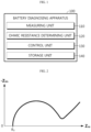
- FIG. 2 is a diagram schematically showing an impedance profile according to an embodiment of the present disclosure.
- the impedance profile may be expressed as an X-Y plane graph when X is set as a real part (Zre) and Y is set as an imaginary part (-Zim).
- the ohmic resistance (Ro) of the battery may be a starting resistance value of the impedance profile.
- the resistance value of the real part (Zre) when the value of the imaginary part (-Zim) is 0 may be the ohmic resistance (Ro) of the battery. Since the ohmic resistance (Ro) is a widely known factor, it should be noted that a description of the ohmic resistance (Ro) will be omitted.
- the impedance profile of the battery may be generated outside the battery diagnosing apparatus 100.
- the ohmic resistance determining unit 120 may directly receive the impedance profile of the battery generated in the outside or may acquire the impedance profile by accessing a memory in which the impedance profile of the battery is stored.
- the ohmic resistance determining unit 120 may determine a starting resistance value from the received impedance profile, and determine the determined starting resistance value as the ohmic resistance of the battery.
- the reference capacity may be a discharge capacity of a battery until the battery in a BOL (Beginning Of Life) state is shifted from a fully charged state to a fully discharged battery.
- the reference capacity may be the discharge capacity of the battery measured while the battery in the BOL state is discharged from 100% SOC (State Of Charge) to 0% SOC.
- control unit 130 may calculate a capacity change rate for the battery by calculating a ratio of a difference between the reference capacity and the measured discharge capacity of the battery for the reference capacity. For example, the control unit 130 may calculate a capacity change rate for the battery by calculating the formula "(reference capacity - measured discharge capacity of a battery) ⁇ reference capacity ⁇ 100".
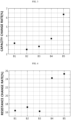
- FIG. 3 is a diagram showing an example of the capacity change rate calculated by the battery diagnosing apparatus 100 according to an embodiment of the present disclosure.
- the control unit 130 may calculate a capacity change rate for first to fifth batteries B1 to B5.
- the reference capacity may be preset for each of the first to fifth batteries B1 to B5. That is, a first reference capacity for the first battery B1 and a second reference capacity for the second battery B2 may be preset.
- a third reference capacity for the third battery B3 and a fourth reference capacity for the fourth battery B4 may be preset.
- a fifth reference capacity for the fifth battery B5 may be preset.
- control unit 130 does not calculate the capacity change rate of the first to fifth batteries B1 to B5 by using one preset reference capacity, but may calculate the capacity change rate for each of the first to fifth batteries B1 to B5 by calculating the difference between the corresponding reference capacity and the measured discharge capacity of the battery. Accordingly, the degree of degradation of each battery may be reflected in the capacity change rate of the battery calculated by the control unit 130.
- the capacity change rate of the first battery B1 may be 3.17%, and the capacity change rate of the second battery B2 may be 2.5%.
- the capacity change rate of the third battery B3 may be 2.83%, and the capacity change rate of the fourth battery B4 may be 3.67%.
- the capacity change rate of the fifth battery B5 may be 6.33%.
- the control unit 130 may be configured to calculate a resistance change rate by comparing the ohmic resistance determined by the ohmic resistance determining unit 120 with a reference resistance.
- control unit 130 may calculate a resistance change rate for the battery by calculating a ratio of a difference between the reference resistance and the measured ohmic resistance of the battery for the reference resistance. For example, the control unit 130 may calculate the resistance change rate for the battery by calculating the formula "(measured ohmic resistance of the battery - reference resistance) ⁇ reference resistance ⁇ 100".
- FIG. 4 is a diagram showing an example of the resistance change rate calculated by the battery diagnosing apparatus 100 according to an embodiment of the present disclosure.
- the control unit 130 may calculate a resistance change rate of the first to fifth batteries B1 to B5.
- the reference resistance may also be preset for each of the first to sixth fifth batteries B1 to B5. That is, a first reference resistance for the first battery B1 and a second reference resistance for the second battery B2 may be preset.
- a third reference resistance for the third battery B3 and a fourth reference resistance for the fourth battery B4 may be preset.
- a fifth reference resistance for the fifth battery B5 may be preset.
- the control unit 130 may calculate a resistance change rate of each of the first to fifth batteries B1 to B5 based on the corresponding reference resistance and the ohmic resistance of the battery.
- the resistance change rate of the first battery B1 may be 16.4%, and the resistance change rate of the second battery B2 may be 17.1%.
- the resistance change rate of the third battery B3 may be 16.1%, and the resistance change rate of the fourth battery B4 may be 24.2%.
- the resistance change rate of the fifth battery B5 may be 25.2%.
- the control unit 130 may be configured to judge an internal gas generation level of the battery by comparing magnitudes of the calculated resistance change rate and a criterion resistance change rate.
- control unit 130 may be configured to judge that an internal gas of the battery equal to or greater than a criterion amount is generated, when the calculated resistance change rate is equal to or greater than the criterion resistance change rate.
- control unit 130 may be configured to judge that an internal gas of the battery less than the criterion amount is generated, when the calculated resistance change rate is less than the criterion resistance change rate.
- the case where the internal gas of the battery less than the criterion amount is generated may include both the case where the internal gas of the battery less than the criterion amount is generated and the case where the internal gas is not generated.
- the criterion resistance change rate is preset to 20%. Since the resistance change rates of the first to third batteries B1 to B3 are smaller than the criterion resistance change rate, the control unit 130 may judge that the internal gas of the first to third batteries B1 to B3 less than the criterion amount is generated. In addition, since the resistance change rates of the fourth and fifth batteries B4, B5 are greater than the criterion resistance change rate, the control unit 130 may judge that the internal gas of the fourth and fifth batteries B4, B5 greater than the criterion amount is generated.
- the control unit 130 may be configured to judge an internal gas generation cause of the battery by comparing magnitudes of the calculated capacity change rate and a criterion capacity change rate.
- control unit 130 may be configured to judge that the internal gas generation cause is a side reaction of the negative electrode of the battery, when the calculated capacity change rate is greater than or equal to the criterion capacity change rate. More preferably, the control unit 130 may be configured to judge that the internal gas generation cause is a side reaction of the negative electrode and an electrolyte of the battery, when the calculated capacity change rate is greater than or equal to the criterion capacity change rate.
- control unit 130 may be configured to judge that the internal gas generation cause is another cause other than the side reaction of the negative electrode, when the calculated capacity change rate is less than the criterion capacity change rate.
- another cause may include a side reaction of the positive electrode of the battery.
- the criterion capacity change rate is preset to 5%. Since the capacity change rates of the first to fourth batteries B1 to B4 are smaller than the criterion capacity change rate, the control unit 130 may judge that the internal gases of the first to fourth batteries B1 to B4 are caused by another cause. In addition, since the capacity change rate of the fifth battery B5 is greater than the criterion capacity change rate, the control unit 130 may judge that the internal gas of the fifth battery B5 is generated by the side reaction of the negative electrode of the corresponding battery.
- the battery diagnosing apparatus 100 may judge whether the internal gas of the battery equal to or greater than the criterion amount is generated and whether the internal gas of the battery is generated due to any side reaction.
- the battery diagnosing apparatus 100 has an advantage of diagnosing in a non-destructive manner whether the internal gas of the battery is generated due to the side reaction of the negative electrode of the battery.
- the battery diagnosing apparatus 100 when diagnosing the state of one or more batteries collected for reuse, the battery diagnosing apparatus 100 according to an embodiment of the present disclosure may be used.
- the battery diagnosing apparatus 100 may diagnose the internal gas generation level and the internal gas generation cause for each of one or more batteries in a non-destructive manner. Therefore, according to an embodiment of the present disclosure, because the internal gas generation level and the internal gas generation cause of the battery may be quickly and easily diagnosed based on the ohmic resistance and the discharge capacity of the battery, it may be judged quickly and accurately whether the collected batteries are reusable.
- control unit 130 provided to the battery diagnosing apparatus 100 may optionally include a processor, an application-specific integrated circuit (ASIC), another chipset, a logic circuit, a register, a communication modem, and a data processing device, and the like, known in the art to execute various control logics performed in the present disclosure.
- control logic when the control logic is implemented in software, the control unit 130 may be implemented as a set of program modules.
- the program module may be stored in a memory and executed by the control unit 130.
- the memory may be provided in or out of the control unit 130, and may be connected to the control unit 130 by various well-known means.
- the battery diagnosing apparatus 100 may further include a storage unit 140.
- the storage unit 140 may store data or programs necessary for operation and function of each component of the battery diagnosing apparatus 100, data generated in the process of performing the operation or function, or the like.
- the storage unit 140 is not particularly limited in its kind as long as it is a known information storage means that can record, erase, update and read data.
- the information storage means may include RAM, flash memory, ROM, EEPROM, registers, and the like.
- the storage unit 140 may store program codes in which processes executable by the control unit 130 are defined.
- the storage unit 140 may store a reference capacity and a reference resistance for each battery.
- the storage unit 140 may store the impedance profile of the battery.
- the ohmic resistance determining unit 120 may access the storage unit 140 to obtain the impedance profile of the battery.
- the ohmic resistance determining unit 120 may be configured to determine the ohmic resistance based on the impedance profile generated for the battery, when a temperature of the battery measured by the measuring unit 110 is equal to or greater than a criterion temperature during a predetermined period.
- the predetermined period may be a minimum period in which the temperature of the battery must be maintained at the criterion temperature or above so that the change in the ohmic resistance of the battery may be related to the generation of internal gas of the battery. That is, if the temperature of the battery is maintained at the criterion temperature or above only during too short a period, the generated internal gas of the battery may not be significantly related to the change in the ohmic resistance of the battery. Therefore, in the present disclosure, by maintaining the temperature of the battery at the criterion temperature or above during a predetermined period, it is possible to make judgment by correlating the change in the ohmic resistance of the battery and the internal gas generation level of the battery.
- the criterion temperature may be set to any one of 40°C to 60°C.
- the criterion temperature may be set to 40°C.
- the predetermined period may be set to any one of 3 days to 8 days.
- the predetermined period may be set to 3 days.
- the criterion temperature is set to 40°C and the predetermined period is set to 3 days.
- the ohmic resistance determining unit 120 may determine the ohmic resistance for the corresponding battery by acquiring the impedance profile for the corresponding battery.
- the battery diagnosing apparatus 100 may perform diagnosis for a battery that is maintained at the criterion temperature or above during a predetermined period.
- the battery may be initially fully charged to the SOC 100% state.
- the fully charged battery may be maintained at the criterion temperature or above for a predetermined period. That is, during the predetermined period, the fully charged battery may be gradually discharged naturally, but the temperature of the battery may be configured to be maintained at the criterion temperature or above.
- the measuring unit 110 may also measure the discharge capacity only for a battery whose temperature is maintained at the criterion temperature or above for a predetermined period, and the control unit 130 may diagnose the internal gas generation level and the internal gas generation cause only for the corresponding battery.
- the battery may be fully charged again at a first time point after the battery is maintained at the criterion temperature or above for the predetermined period, and may be configured to be fully discharged at a second time point after the battery is fully charged at the first time point.
- the measuring unit 110 may be configured to measure the discharge capacity of the battery until the battery fully charged at the first time point is fully discharged at the second time point.
- the battery may be fully charged to SOC 100% at the first time point.
- the battery may be fully discharged to SOC 0%.
- the measuring unit 110 may measure the discharge capacity of the battery from the first time point to the second time point.
- the control unit 130 may calculate a capacity change rate of the battery based on the discharge capacity measured by the measuring unit 110. That is, the control unit 130 may calculate a loss rate of the irreversible capacity of the battery.
- the battery diagnosing apparatus 100 may judge whether the internal gas of the battery is generated, and, if generated, due to which cause the internal gas of the battery is generated, only when the fully charged battery is maintained at the criterion temperature or above for a predetermined period, in order to create a test environment in which the internal gas of the battery may be generated.
- the battery diagnosing apparatus 100 diagnoses the state of the battery according to the diagnosed internal gas generation level and the internal gas generation cause of the battery will be described in detail.
- the control unit 130 may be configured to diagnose the state of the battery based on the internal gas generation level and the internal gas generation cause.
- the state of the battery that may be judged by the control unit 130 is divided into a normal state, a first warning state, and a second warning state.
- the state of the battery that may be judged by the control unit 130 may be further subdivided according to the internal gas generation level and the internal gas generation cause of the battery.
- the control unit 130 may specifically subdivide and diagnose the internal gas generation level of the battery by comparing the calculated resistance change rate of the battery with a criterion resistance range divided into a plurality of sections.
- the control unit 130 may compare the calculated capacity change rate of the battery with a criterion capacity range divided into a plurality of capacity sections to subdivide and diagnose the internal gas generation cause of the battery in more detail.
- the state of the battery may be specifically diagnosed in more various aspects by the internal gas generation level and the internal gas generation cause that are subdivided and diagnosed.
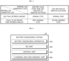
- FIG. 5 is a diagram schematically showing a state of a battery diagnosed by the battery diagnosing apparatus 100 according to an embodiment of the present disclosure.
- control unit 130 may be configured to diagnose that the state of the battery is a normal state, when it is judged that the internal gas less than the criterion amount is generated.
- control unit 130 may diagnose that the state of the battery is a normal state. In addition, the control unit 130 may classify the battery as a reusable battery.
- control unit 130 may be configured to diagnose that the state of the battery is a first warning state, when it is judged that the internal gas equal to or greater than the criterion amount is generated due to another cause.
- control unit 130 may classify the battery as a reusable battery.
- control unit 130 may be configured to decrease an upper limit temperature of the battery in order to reduce the internal gas generation amount of the battery diagnosed as the first warning state. That is, the battery diagnosed as the first warning state may be set by the control unit 130 so that the allowable upper limit temperature is reduced. That is, when the battery diagnosed as the first warning state is reused, the allowable upper limit temperature for the battery may be limited to the temperature set by the control unit 130.
- control unit 130 may be configured to diagnose that the state of the battery is a second warning state, when it is judged that the internal gas equal to or greater than the criterion amount is generated by the side reaction of the negative electrode. In addition, the control unit 130 may classify the battery as a reusable battery.
- control unit 130 may be configured to decrease at least one of an upper limit temperature and an upper limit C-rate for the battery in order to decrease the internal gas generation amount of the battery diagnosed as the second warning state. That is, the battery diagnosed as the second warning state may be set by the control unit 130 such that at least one of the allowable upper limit temperature and the allowable upper limit C-rate is reduced.
- the control unit 130 may reduce both the upper limit temperature and the upper limit C-rate of the battery in order to effectively reduce the internal gas generation amount of the battery diagnosed as the second warning state. That is, when the battery diagnosed as the second warning state is reused, at least one of the upper limit temperature and the upper limit C-rate allowable for the corresponding battery may be limited to a value set by the control unit 130.
- control unit 130 may diagnose that the state of the battery having the internal gas generation level equal to or greater than the criterion amount is a warning state, and decrease the upper limit temperature and/or the upper limit C-rate in order to reduce the internal gas generation amount.
- control unit 130 may classify a battery diagnosed as the normal state, the first warning state or the second warning state as a reusable battery. In addition, the control unit 130 may reduce the internal gas generation amount of the battery when the battery is reused by appropriately restricting the operation of the battery diagnosed as the first warning state or the second warning state.
- the battery diagnosing apparatus 100 may diagnose the state of the battery by focusing on whether the battery is reusable based on the internal gas generation level and the internal gas generation cause of the battery.
- the operation of each battery may be limited based on the diagnosed state. Therefore, the battery diagnosing apparatus 100 has an advantage of not only judging whether to the battery is reusable, but also setting appropriate control conditions so that the battery may be used for a longer period.
- FIG. 6 is a diagram schematically showing a battery diagnosing system 10 according to another embodiment of the present disclosure.
- the battery diagnosing system 10 may include a battery diagnosing apparatus 100 according to an embodiment of the present disclosure and an EIS unit 200.
- the EIS unit 200 may be configured to output an AC current to the battery and generate an impedance profile representing the impedance of the battery as a corresponding relationship between the real part (Zre) and the imaginary part (-Zim) according to the output result of the AC current.
- the EIS unit 200 may be configured to perform EIS (Electrochemical Impedance Spectroscopy). Therefore, the EIS unit 200 may apply a minute AC current to the battery to measure the impedance of the battery, and generate an impedance profile representing the impedance as a corresponding relationship between the real part (Zre) and the imaginary part (-Zim).
- EIS Electrochemical Impedance Spectroscopy
- the EIS unit 200 may measure the impedance of the battery when the temperature of the battery becomes close to room temperature.
- the EIS unit 200 may be configured to output the generated impedance profile to the battery diagnosing apparatus 100.
- the EIS unit 200 may transmit the generated impedance profile to the ohmic resistance determining unit 120 of the battery diagnosing apparatus 100.
- the EIS unit 200 may transmit the generated impedance profile to the storage unit 140 of the battery diagnosing apparatus 100.
- the ohmic resistance determining unit 120 may access the storage unit 140 to acquire the impedance profile generated by the EIS unit 200.
- the battery diagnosing system 10 may further include a heating unit 300 and a charging and discharging unit 400.
- the heating unit 300 may be configured to increase the temperature of the battery so that the temperature of the battery is equal to or higher than a criterion temperature. That is, the heating unit 300 may raise and maintain the temperature of the battery so that the temperature of the battery may be maintained at the criterion temperature or above for a predetermined period.
- the charging and discharging unit 400 may be configured to be connected to a battery to charge or discharge the battery.
- the battery may be fully charged by the charging and discharging unit 400 at an initial time point.
- the temperature of the battery may be maintained at the criterion temperature or above by the heating unit 300 for a predetermined period.
- the charging and discharging unit 400 may fully charge the battery again at a first time point after a predetermined period has elapsed. That is, the SOC of the battery at the first time point may be 100%.
- the charging and discharging unit 400 may fully discharge the battery. That is, the SOC of the battery at the second time point may be 0%.
- the measuring unit 110 may measure the discharge capacity of the battery from the first time point to the second time point.
- the control unit 130 may diagnose the internal gas generation level, the internal gas generation cause and the state of the battery.
- the battery diagnosing system 10 has an advantage of diagnosing whether the battery is reusable by satisfying the test conditions in which the internal gas of the battery may be generated.
- the battery diagnosing apparatus 100 may perform additional diagnosis to specifically identify the internal gas generation cause of the battery. That is, the battery diagnosing apparatus 100 may perform additional diagnosis in order to specifically diagnose the internal gas generation cause of the battery in preparation for judging that the state of the battery as the first warning state.
- the measuring unit 110 may be configured to further measure a voltage of the battery.
- the measuring unit 110 may measure the voltage of a battery that is maintained at the criterion temperature or above for a predetermined period. More preferably, the measuring unit 110 may measure an OCV (Open Circuit Voltage) of the battery.
- OCV Open Circuit Voltage
- the control unit 130 may be configured to calculate a voltage change amount by comparing the voltage of the battery measured by the measuring unit 110 with a reference voltage.
- the reference voltage may be a voltage value measured in advance for a battery in the BOL state. More preferably, the reference voltage may be an OCV value measured when the SOC of the battery in the BOL state is 100%.
- control unit 130 may calculate the voltage change amount for the battery by calculating a difference between the reference voltage and the measured voltage of the battery. For example, the control unit 130 may calculate the voltage change amount for the battery by calculating the formula "reference voltage - measured voltage of the battery".
- control unit 130 may be configured to judge that the internal gas generation cause of the battery is a side reaction of the positive electrode.
- control unit 130 may be configured to diagnose that the state of the battery is a third warning state, when it is judged that the internal gas of the battery equal to or greater than the criterion amount is generated by the side reaction of the positive electrode. In addition, the control unit 130 may classify the battery as a reusable battery.
- control unit 130 may be configured to reduce at least one of the upper limit temperature and the upper limit SOC for the battery in order to reduce the internal gas generation amount of the battery diagnosed as the third warning state. That is, the battery diagnosed as the third warning state may be set by the control unit 130 such that at least one of the allowable upper limit temperature and the upper limit SOC is reduced. That is, when a battery diagnosed as the third warning state is reused, the allowable upper limit temperature and/or the upper limit SOC for the battery may be limited to a value set by the control unit 130.
- the battery diagnosing apparatus 100 according to the present disclosure may be applied to a BMS (Battery Management System). That is, the BMS according to the present disclosure may include the battery diagnosing apparatus 100 described above. In this configuration, at least some components of the battery diagnosing apparatus 100 may be implemented by supplementing or adding functions of the configuration included in the conventional BMS.
- BMS Battery Management System
- the battery diagnosing apparatus 100 may be provided to a battery pack. That is, the battery pack according to the present disclosure may include the above-described battery diagnosing apparatus 100 and at least one battery. In addition, the battery pack may further include electrical equipment (a relay, a fuse, etc.) and a case.
- electrical equipment a relay, a fuse, etc.
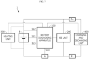
- FIG. 7 is a diagram schematically showing an exemplary configuration of a battery pack 1 according to still another embodiment of the present disclosure.
- the battery pack 1 may include a battery diagnosing apparatus 100, an EIS unit 200, a heating unit 300, and a charging and discharging unit 400. That is, the battery pack 1 may include the battery diagnosing system 10.
- the battery diagnosing apparatus 100 may be connected to first to fourth sensing lines SL1 to SL4.
- the first to fourth sensing lines SL1 to SL4 may be connected to the measuring unit 110 of the battery diagnosing apparatus 100.
- the measuring unit 110 may measure the temperature of the battery B through the first sensing line SL1.
- the measuring unit 110 may measure a positive electrode discharge capacity of the battery B through the second sensing line SL2 and measure a negative electrode discharge capacity of the battery B through the third sensing line SL3. In addition, the measuring unit 110 may measure the discharge capacity of the battery B by calculating a difference between the measured positive electrode discharge capacity and negative electrode discharge capacity of the battery B.
- the measuring unit 110 may be connected to a current measuring element A through the fourth sensing line SL4.
- the current measuring element A may be a current system or a shunt resistor. Therefore, the measuring unit 110 may measure the current of the battery B through the fourth sensing line SL4.
- FIG. 7 shows an embodiment in which the current measuring element A is provided between a negative electrode of the battery B and a negative electrode terminal P- of the battery pack 1 as a preferred embodiment, but the current measuring element A may also be provided between a positive electrode of the battery B and a positive electrode terminal P+ of the battery pack 1.
- One end of the EIS unit 200 may be connected between the positive electrode terminal P+ of the battery pack 1 and the positive electrode of the battery B, and the other end may be connected between the negative electrode terminal P- of the battery pack 1 and the negative electrode of the battery B.
- the EIS unit 200 may measure the impedance of the battery B after outputting a minute AC current. Thereafter, the EIS unit 200 may generate an impedance profile of the battery B and transmit it to the battery diagnosing apparatus 100.
- One end of the heating unit 300 may be connected to the positive electrode of the battery B, and the other end may be connected to the negative electrode of the battery cell B.
- the operation of the heating unit 300 is controlled by the battery diagnosing apparatus 100 (particularly, the control unit 130), and when the heating unit 300 is operated, the temperature of the battery B may increase.
- One end of the charging and discharging unit 400 may be connected to the positive electrode terminal P+ of the battery pack 1, and the other end may be connected to the negative electrode terminal P- of the battery pack 1.
- one end of the charging and discharging unit 400 may be directly connected to the positive electrode of the battery B, and the other end may be directly connected to the negative electrode of the battery B, similarly to the heating unit 300.
- the operation of the charging and discharging unit 400 may be controlled by the battery diagnosing apparatus 100 (particularly, the control unit 130), and when the charging and discharging unit 400 is operated, the battery B may be charged or discharged.
- the battery B may be fully charged by the charging and discharging unit 400.
- the temperature of the battery B may be maintained at the criterion temperature or above for a predetermined period. Thereafter, the internal gas generation level, the internal gas generation cause and the state of the battery B may be diagnosed by the battery diagnosing apparatus 100.
- FIG. 8 is a diagram showing a battery diagnosing method according to still another embodiment of the present disclosure.
- each step of the battery diagnosing method may be performed by the battery diagnosing apparatus 100.
- the battery diagnosing apparatus 100 For convenience of explanation, content overlapping with the previously described content will be briefly described or omitted.
- the battery diagnosing method may include a temperature measuring step (S100), an ohmic resistance determining step (S200), a discharge capacity measuring step (S300), a capacity change rate calculating step (S400), a resistance change rate calculating step (S500), an internal gas generation level judging step (S600), and an internal gas generation cause judging step (S700).
- S100 temperature measuring step
- S200 ohmic resistance determining step
- S300 discharge capacity measuring step
- S400 capacity change rate calculating step
- S500 resistance change rate calculating step
- S600 internal gas generation level judging step
- S700 internal gas generation cause judging step
- the temperature measuring step (S100) is a step of measuring the temperature of the battery, and may be performed by the measuring unit 110.
- the measuring unit 110 may be connected to a battery through a first sensing line SL1.
- the measuring unit 110 may measure the temperature of the battery through the first sensing line SL1.
- the ohmic resistance determining step (S200) is a step of determining the ohmic resistance of the battery based on the impedance profile generated for the battery, and may be performed by the ohmic resistance determining unit 120.
- the ohmic resistance determining unit 120 may determine the ohmic resistance only for a battery in which the temperature of the battery measured by the measuring unit 110 is equal to or greater than the criterion temperature and this state is maintained for a predetermined period.
- the discharge capacity measuring step (S300) is a step of measuring a discharge capacity of the battery, and may be performed by the measuring unit 110.
- the battery whose temperature is maintained at the criterion temperature or above for a predetermined period may be fully charged again after the predetermined period has elapsed. Thereafter, the fully charged battery may be fully discharged.
- the measuring unit 110 may measure the discharge capacity of the battery while the fully charged battery is fully discharged.
- the measuring unit 110 may be connected to a current measuring element A through a fourth sensing line SL4.
- the measuring unit 110 may measure the discharge capacity of the battery through the current measuring element A.
- the capacity change rate calculating step (S400) is a step of calculating a capacity change rate by comparing the discharge capacity of the battery measured in the discharge capacity measuring step (S300) with a reference capacity, and may be performed by the control unit 130.
- control unit 130 may calculate the capacity change rate of the battery by calculating the formula "(reference capacity - measured discharge capacity of the battery) ⁇ reference capacity ⁇ 100".
- the resistance change rate calculating step (S500) is a step of calculating a resistance change rate by comparing the ohmic resistance determined in the ohmic resistance determining step (S200) with a reference resistance, and may be performed by the control unit 130.
- control unit 130 may calculate the resistance change rate of the battery by calculating the formula "(determined ohmic resistance - reference resistance) ⁇ reference resistance ⁇ 100".
- the internal gas generation level judging step (S600) is a step of judging an internal gas generation level of the battery by comparing magnitudes of the calculated resistance change rate and a criterion resistance change rate, and may be performed by the control unit 130.
- the control unit 130 may judge that the internal gas of the battery equal to or greater than the criterion amount is generated. Conversely, if the calculated resistance change rate is less than the criterion resistance change rate, the control unit 130 may judge that the internal gas of the battery less than the criterion amount is generated.
- the internal gas generation cause judging step (S700) is a step of judging the internal gas generation cause of the battery by comparing the magnitudes of the calculated capacity change rate and the criterion capacity change rate, and may be performed by the control unit 130.
- the control unit 130 may judge that the internal gas of the battery is generated by a side reaction of the negative electrode of the battery. Conversely, if the calculated capacity change rate is less than the criterion capacity change rate, the control unit 130 may judge that the internal gas of the battery is caused by another cause other than the side reaction of the negative electrode of the battery.
- the battery diagnosing method may further include a battery state diagnosing step after the internal gas generation cause judging step (S700).
- the battery state diagnosing step is a step of diagnosing the state of the battery based on the internal gas generation level and the internal gas generation cause, and may be performed by the control unit 130.
- control unit 130 may diagnose the state of the battery as a normal state, a first warning state, or a second warning state based on the internal gas generation level and the internal gas generation cause.
- control unit 130 may classify a battery diagnosed as the normal state, the first warning state or the second warning state as a reusable battery.
- control unit 130 may reduce the internal gas generation amount of the battery when the battery is reused by appropriately restricting the operation of the battery diagnosed as the first warning state or the second warning state.
- an additional diagnosing step may be performed to more specifically confirm the internal gas generation cause of the battery.
- the additional diagnosing step is a step of diagnosing whether the internal gas generation cause of the battery is the side reaction of the positive electrode, and may be performed by the control unit 130.
- the embodiments of the present disclosure described above may not be implemented only through an apparatus and a method, but may be implemented through a program that realizes a function corresponding to the configuration of the embodiments of the present disclosure or a recording medium on which the program is recorded.
- the program or recording medium may be easily implemented by those skilled in the art from the above description of the embodiments.
Landscapes
- Engineering & Computer Science (AREA)
- Manufacturing & Machinery (AREA)
- Chemical & Material Sciences (AREA)
- Chemical Kinetics & Catalysis (AREA)
- Electrochemistry (AREA)
- General Chemical & Material Sciences (AREA)
- General Physics & Mathematics (AREA)
- Physics & Mathematics (AREA)
- Microelectronics & Electronic Packaging (AREA)
- Power Engineering (AREA)
- Health & Medical Sciences (AREA)
- General Health & Medical Sciences (AREA)
- Medical Informatics (AREA)
- Secondary Cells (AREA)
- Tests Of Electric Status Of Batteries (AREA)
- Charge And Discharge Circuits For Batteries Or The Like (AREA)
Claims (13)
- Batteriediagnosevorrichtung (100) aufweisend:eine Messeinheit (110) Eingerichtet zum Messen einer Entladekapazität und eine Temperatur einer Batterie; undeine Ohmscher-Widerstand-Bestimmungseinheit (120) eingerichtet zum Bestimmen eines ohmschen Widerstands der Batterie basierend auf einem für die Batterie erzeugten Impedanzprofil,gekennzeichnet durcheine Steuereinheit (130) eingerichtet zum Berechnen einer Kapazitätsänderungsrate durch Vergleichen der durch die Messeinheit (110) gemessenen Entladekapazität der Batterie mit einer Referenzkapazität, Berechnen einer Widerstandsänderungsrate durch Vergleichen des durch die Ohmscher-Widerstand-Bestimmungseinheit (120) bestimmten ohmschen Widerstands mit einem Referenzwiderstand, Beurteilen eines internen Gaserzeugungspegels der Batterie durch Vergleichen von Größen der berechneten Widerstandsänderungsrate und einer Kriterium-Widerstandsänderungsrate, und Beurteilen einer internen Gaserzeugungsursache der Batterie durch Vergleichen von Größen der berechneten Kapazitätsänderungsrate und einer Kriterium-Kapazitätsänderungsrate.
- Batteriediagnosevorrichtung nach Anspruch 1,
wobei die Ohmscher-Widerstand-Bestimmungseinheit (120) eingerichtet ist zum Bestimmen des ohmschen Widerstands basierend auf dem für die Batterie erzeugten Impedanzprofil, wenn die durch die Messeinheit (110) gemessene Temperatur der Batterie gleich oder größer als eine Kriterium-Temperatur während eines vorbestimmten Zeitraums ist. - Batteriediagnosevorrichtung nach Anspruch 2,wobei die Batterie eingerichtet ist, während des vorbestimmten Zeitraums bei der Kriterium-Temperatur oder darüber gehalten zu werden, und dann zu einem ersten Zeitpunkt vollständig geladen und dann zu einem zweiten Zeitpunkt vollständig entladen zu werden, undwobei die Messeinheit (110) eingerichtet ist zum Messen einer Entladekapazität der Batterie, bis die zum ersten Zeitpunkt vollständig geladene Batterie zum zweiten Zeitpunkt vollständig entladen ist.
- Batteriediagnosevorrichtung nach Anspruch 1,wobei die Steuereinheit (130) eingerichtet ist zum Beurteilen, dass ein internes Gas der Batterie gleich oder größer als ein Kriterium-Betrag erzeugt wird, wenn die berechnete Widerstandsänderungsrate gleich oder größer als die Kriterium-Widerstandsänderungsrate ist, undwobei die Steuereinheit (130) eingerichtet ist zum Beurteilen, dass ein internes Gas der Batterie kleiner als der Kriterium-Betrag erzeugt wird, wenn die berechnete Widerstandsänderungsrate kleiner als die Kriterium-Widerstandsänderungsrate ist.
- Batteriediagnosevorrichtung nach Anspruch 4,wobei die Steuereinheit (130) eingerichtet ist zum Beurteilen, dass die interne Gaserzeugungsursache eine Seitenreaktion einer negativen Elektrode der Batterie ist, wenn die berechnete Kapazitätsänderungsrate gleich oder größer als die Kriterium-Kapazitätsänderungsrate ist, undwobei die Steuereinheit (130) eingerichtet ist zum Beurteilen, dass die interne Gaserzeugungsursache eine andere Ursache als die Seitenreaktion der negativen Elektrode ist, wenn die berechnete Kapazitätsänderungsrate kleiner als die Kriterium-Kapazitätsänderungsrate ist.
- Batteriediagnosevorrichtung nach Anspruch 5,
wobei die Steuereinheit (130) eingerichtet ist zum Diagnostizieren eines Zustands der Batterie basierend auf dem internen Gaserzeugungspegel und der internen Gaserzeugungsursache. - Batteriediagnosevorrichtung nach Anspruch 6,
wobei die Steuereinheit (130) eingerichtet ist zum Diagnostizieren, dass der Zustand der Batterie ein normaler Zustand ist, wenn beurteilt wird, dass das interne Gas kleiner als der Kriterium-Betrag erzeugt wird. - Batteriediagnosevorrichtung nach Anspruch 6,
wobei, wenn beurteilt wird, dass das interne Gas gleich oder größer als der Kriterium-Betrag aufgrund der anderen Ursache erzeugt wird, die Steuereinheit (130) eingerichtet ist zum Diagnostizieren, dass der Zustand der Batterie ein erster Warnzustand ist, und zum Reduzieren einer oberen Grenztemperatur für die Batterie. - Batteriediagnosevorrichtung nach Anspruch 6,
wobei, wenn beurteilt wird, dass das interne Gas gleich oder größer als der Kriterium-Betrag aufgrund der Seitenreaktion der negativen Elektrode erzeugt wird, die Steuereinheit (130) eingerichtet ist zum Diagnostizieren, dass der Zustand der Batterie ein zweiter Warnzustand ist, und zum Reduzieren einer oberen Grenztemperatur und/oder einer oberen Grenz-C-Rate für die Batterie. - Batteriediagnosesystem (10) aufweisend:
die Batteriediagnosevorrichtung (100) nach einem der Ansprüche 1 bis 9; und
eine EIS-Einheit (200) eingerichtet zum Ausgeben eines Wechselstroms an die Batterie, zum Erzeugen eines Impedanzprofils, das eine Impedanz der Batterie repräsentiert, gemäß einem Ausgabeergebnis des Wechselstroms als eine entsprechende Beziehung zwischen einem Realteil und einem Imaginärteil, und zum Ausgeben des erzeugten Impedanzprofils an die Batteriediagnosevorrichtung. - Batteriediagnosesystem nach Anspruch 10, ferner aufweisend:eine Heizeinheit (300) eingerichtet zum Erhöhen einer Temperatur der Batterie, so dass die Temperatur der Batterie gleich oder größer als eine Kriterium-Temperatur wird; undeine Lade- und Entladeeinheit (400) eingerichtet zum Laden und Entladen der Batterie.
- Batteriepack aufweisend die Batteriediagnosevorrichtung nach einem der Ansprüche 1 bis 9.
- Batteriediagnoseverfahren aufweisend:einen Temperaturmessschritt (S100) zum Messen einer Temperatur einer Batterie;einen Ohmscher-Widerstand-Bestimmungsschritt (S200) zum Bestimmen eines ohmschen Widerstands der Batterie basierend auf einem für die Batterie erzeugten Impedanzprofil; undeinen Entladekapazitätsmessschritt (S300) zum Messen einer Entladekapazität der Batterie,gekennzeichnet durcheinen Kapazitätsänderungsratenberechnungsschritt (S400) zum Berechnen einer Kapazitätsänderungsrate durch Vergleichen der im Messschritt (S300) gemessenen Entladekapazität der Batterie mit einer Referenzkapazität;einen Widerstandsänderungsratenberechnungsschritt (S500) zum Berechnen einer Widerstandsänderungsrate durch Vergleichen des im Ohmscher-Widerstand-Bestimmungsschritt (S200) bestimmten ohmschen Widerstands mit einem Referenzwiderstand;einen Interner-Gaserzeugungspegel-Beurteilungsschritt (S600) zum Beurteilen eines internen Gaserzeugungspegels der Batterie durch Vergleichen von Größen der berechneten Widerstandsänderungsrate und einer Kriterium-Widerstandsänderungsrate; undeinen Interner-Gaserzeugungsursache-Beurteilungsschritt (S700) zum Beurteilen einer internen Gaserzeugungsursache der Batterie durch Vergleichen von Größen der berechneten Kapazitätsänderungsrate und einer Kriterium-Kapazitätsänderungsrate.
Applications Claiming Priority (2)
| Application Number | Priority Date | Filing Date | Title |
|---|---|---|---|
| KR1020200131451A KR102759313B1 (ko) | 2020-10-12 | 2020-10-12 | 배터리 진단 장치 및 방법 |
| PCT/KR2021/014053 WO2022080837A1 (ko) | 2020-10-12 | 2021-10-12 | 배터리 진단 장치 및 방법 |
Publications (3)
| Publication Number | Publication Date |
|---|---|
| EP4131573A1 EP4131573A1 (de) | 2023-02-08 |
| EP4131573A4 EP4131573A4 (de) | 2023-12-06 |
| EP4131573B1 true EP4131573B1 (de) | 2024-09-25 |
Family
ID=81208508
Family Applications (1)
| Application Number | Title | Priority Date | Filing Date |
|---|---|---|---|
| EP21880484.7A Active EP4131573B1 (de) | 2020-10-12 | 2021-10-12 | Batteriediagnosevorrichtung und -verfahren |
Country Status (9)
| Country | Link |
|---|---|
| US (1) | US11929472B2 (de) |
| EP (1) | EP4131573B1 (de) |
| JP (1) | JP7404612B2 (de) |
| KR (1) | KR102759313B1 (de) |
| CN (1) | CN115428230B (de) |
| ES (1) | ES2998683T3 (de) |
| HU (1) | HUE069101T2 (de) |
| PL (1) | PL4131573T3 (de) |
| WO (1) | WO2022080837A1 (de) |
Families Citing this family (6)
| Publication number | Priority date | Publication date | Assignee | Title |
|---|---|---|---|---|
| KR20230166599A (ko) | 2022-05-31 | 2023-12-07 | 충북대학교 산학협력단 | 배터리 상태를 고려한 충전 지령 생성장치 및 이를 포함하는 충전 시스템 |
| KR20250020199A (ko) * | 2023-08-03 | 2025-02-11 | 주식회사 엘지에너지솔루션 | 배터리 진단 장치 및 방법 |
| KR102703316B1 (ko) * | 2023-11-09 | 2024-09-05 | 주식회사 민테크 | 배터리 진단 장치 및 이를 이용한 배터리 진단 방법 |
| CN117347869B (zh) * | 2023-12-04 | 2024-03-01 | 深圳三晖能源科技有限公司 | 储能电池管理系统数据分析方法、装置、电子设备及介质 |
| KR102815154B1 (ko) * | 2023-12-08 | 2025-06-02 | 주식회사 엘지에너지솔루션 | 서버 및 배터리 셀의 활성 영역을 진단하는 방법 |
| KR20250162217A (ko) * | 2024-05-10 | 2025-11-18 | 주식회사 엘지에너지솔루션 | 배터리 진단 방법 및 장치 |
Family Cites Families (20)
| Publication number | Priority date | Publication date | Assignee | Title |
|---|---|---|---|---|
| KR20070020322A (ko) * | 2003-06-23 | 2007-02-20 | 야자키 소교 가부시키가이샤 | 배터리의 열화 판정 방법 및 장치 |
| CN100511781C (zh) | 2004-12-22 | 2009-07-08 | 松下电器产业株式会社 | 复合负极活性材料及其制备方法以及非水电解质二次电池 |
| JP2007103351A (ja) | 2005-09-06 | 2007-04-19 | Denso Corp | 蓄電池の劣化判定方法及びその装置 |
| US7507497B2 (en) | 2005-09-06 | 2009-03-24 | Denso Corporation | Method and apparatus for judging degradation of storage battery |
| KR101583373B1 (ko) | 2010-11-11 | 2016-01-07 | 주식회사 엘지화학 | 이차전지 내부 발생 가스의 실시간 분석 장치 |
| US8877370B2 (en) * | 2010-11-12 | 2014-11-04 | Samsung Sdi Co., Ltd. | Battery pack having a sensor a gas sensor in the cap assembly |
| JP2013089423A (ja) | 2011-10-17 | 2013-05-13 | Nissan Motor Co Ltd | 電池制御装置 |
| US9933491B2 (en) * | 2012-02-03 | 2018-04-03 | Toyota Jidosha Kabushiki Kaisha | Electric storage system |
| JP2013253991A (ja) | 2012-11-30 | 2013-12-19 | Gs Yuasa Corp | 蓄電素子の劣化後容量推定装置、劣化後容量推定方法及び蓄電システム |
| JP6148879B2 (ja) | 2013-02-28 | 2017-06-14 | 旭化成株式会社 | 二次電池の電池状態推定装置及び電池パックの製造方法並びにセルバランス確認方法 |
| KR102082866B1 (ko) * | 2013-04-18 | 2020-04-14 | 삼성에스디아이 주식회사 | 배터리 관리 시스템 및 그 구동방법 |
| CN104865536B (zh) * | 2015-06-16 | 2018-01-02 | 天津力神电池股份有限公司 | 一种锂离子电池性能衰减原因的测试及诊断方法 |
| KR102130724B1 (ko) | 2016-01-08 | 2020-07-06 | 주식회사 엘지화학 | 코인셀을 이용한 내부 가스 발생량 측정 장치 |
| KR102240161B1 (ko) | 2016-08-30 | 2021-04-13 | 삼성에스디아이 주식회사 | 배터리 관리 시스템 |
| KR102258833B1 (ko) | 2017-09-28 | 2021-05-31 | 주식회사 엘지에너지솔루션 | 리튬 이온 배터리 셀의 퇴화 정보를 획득하는 장치 |
| KR102343422B1 (ko) | 2018-04-10 | 2021-12-24 | 주식회사 엘지에너지솔루션 | 배터리 진단 장치 및 방법 |
| US10502791B1 (en) | 2018-09-04 | 2019-12-10 | Lg Chem, Ltd. | System for determining an accurate ohmic resistance value associated with a battery cell |
| JP6991616B2 (ja) | 2018-10-30 | 2022-01-12 | エンネット株式会社 | 電流パルス法による電池診断装置及び電池診断方法 |
| KR102152572B1 (ko) * | 2019-03-22 | 2020-09-07 | 영남대학교 산학협력단 | 이차 전지의 팽창 센싱 시스템 |
| KR102307109B1 (ko) | 2019-05-14 | 2021-09-30 | 이기철 | 원료 이송용 튜브형 디스크 컨베이어 |
-
2020
- 2020-10-12 KR KR1020200131451A patent/KR102759313B1/ko active Active
-
2021
- 2021-10-12 WO PCT/KR2021/014053 patent/WO2022080837A1/ko not_active Ceased
- 2021-10-12 PL PL21880484.7T patent/PL4131573T3/pl unknown
- 2021-10-12 US US17/922,410 patent/US11929472B2/en active Active
- 2021-10-12 ES ES21880484T patent/ES2998683T3/es active Active
- 2021-10-12 JP JP2022554333A patent/JP7404612B2/ja active Active
- 2021-10-12 CN CN202180026830.XA patent/CN115428230B/zh active Active
- 2021-10-12 HU HUE21880484A patent/HUE069101T2/hu unknown
- 2021-10-12 EP EP21880484.7A patent/EP4131573B1/de active Active
Also Published As
| Publication number | Publication date |
|---|---|
| HUE069101T2 (hu) | 2025-02-28 |
| KR20220048371A (ko) | 2022-04-19 |
| WO2022080837A1 (ko) | 2022-04-21 |
| PL4131573T3 (pl) | 2025-01-20 |
| KR102759313B1 (ko) | 2025-01-22 |
| ES2998683T3 (en) | 2025-02-21 |
| EP4131573A1 (de) | 2023-02-08 |
| JP7404612B2 (ja) | 2023-12-26 |
| EP4131573A4 (de) | 2023-12-06 |
| JP2023517587A (ja) | 2023-04-26 |
| US20230198038A1 (en) | 2023-06-22 |
| US11929472B2 (en) | 2024-03-12 |
| CN115428230A (zh) | 2022-12-02 |
| CN115428230B (zh) | 2025-02-21 |
Similar Documents
| Publication | Publication Date | Title |
|---|---|---|
| EP4131573B1 (de) | Batteriediagnosevorrichtung und -verfahren | |
| US12210065B2 (en) | Battery diagnosing apparatus and method | |
| EP3989330B1 (de) | Vorrichtung und verfahren zur diagnose des verschleissgrades einer batterie | |
| US20240044995A1 (en) | Battery Management Apparatus and Method | |
| US12379418B2 (en) | Apparatus and method for diagnosing state of battery | |
| EP4163655B1 (de) | Batterieverwaltungsvorrichtung und -verfahren | |
| EP4199182B1 (de) | Batteriediagnosevorrichtung und -verfahren | |
| EP4206707B1 (de) | Vorrichtung und verfahren zur batterieüberwachung | |
| EP4471444A1 (de) | Batteriediagnosevorrichtung und -verfahren | |
| EP4376161A1 (de) | Vorrichtung und verfahren zur verwaltung einer batterie | |
| EP4239347B1 (de) | Batteriediagnosesystem und batteriediagnoseverfahren | |
| EP4141461B1 (de) | Vorrichtung, verfahren und system zur batteriediagnose | |
| EP4167345B1 (de) | Batteriediagnosevorrichtung und verfahren | |
| EP4152025A1 (de) | Batteriediagnosevorrichtung und -verfahren | |
| EP4318005B1 (de) | Vorrichtung und verfahren zur schätzung des batteriezustands | |
| EP4468003A1 (de) | Batteriediagnosevorrichtung und -verfahren |
Legal Events
| Date | Code | Title | Description |
|---|---|---|---|
| STAA | Information on the status of an ep patent application or granted ep patent |
Free format text: STATUS: THE INTERNATIONAL PUBLICATION HAS BEEN MADE |
|
| PUAI | Public reference made under article 153(3) epc to a published international application that has entered the european phase |
Free format text: ORIGINAL CODE: 0009012 |
|
| STAA | Information on the status of an ep patent application or granted ep patent |
Free format text: STATUS: REQUEST FOR EXAMINATION WAS MADE |
|
| 17P | Request for examination filed |
Effective date: 20221103 |
|
| AK | Designated contracting states |
Kind code of ref document: A1 Designated state(s): AL AT BE BG CH CY CZ DE DK EE ES FI FR GB GR HR HU IE IS IT LI LT LU LV MC MK MT NL NO PL PT RO RS SE SI SK SM TR |
|
| REG | Reference to a national code |
Ref country code: DE Ref legal event code: R079 Free format text: PREVIOUS MAIN CLASS: H01M0010480000 Ipc: G01R0031389000 Ref country code: DE Ref legal event code: R079 Ref document number: 602021019458 Country of ref document: DE Free format text: PREVIOUS MAIN CLASS: H01M0010480000 Ipc: G01R0031389000 |
|
| A4 | Supplementary search report drawn up and despatched |
Effective date: 20231107 |
|
| RIC1 | Information provided on ipc code assigned before grant |
Ipc: H02J 7/00 20060101ALI20231031BHEP Ipc: H01M 10/615 20140101ALI20231031BHEP Ipc: H01M 10/48 20060101ALI20231031BHEP Ipc: H01M 10/44 20060101ALI20231031BHEP Ipc: H01M 10/42 20060101ALI20231031BHEP Ipc: G01R 31/387 20190101ALI20231031BHEP Ipc: G01R 31/382 20190101ALI20231031BHEP Ipc: G01R 31/392 20190101ALI20231031BHEP Ipc: G01R 31/389 20190101AFI20231031BHEP |
|
| DAV | Request for validation of the european patent (deleted) | ||
| DAX | Request for extension of the european patent (deleted) | ||
| GRAP | Despatch of communication of intention to grant a patent |
Free format text: ORIGINAL CODE: EPIDOSNIGR1 |
|
| STAA | Information on the status of an ep patent application or granted ep patent |
Free format text: STATUS: GRANT OF PATENT IS INTENDED |
|
| RIC1 | Information provided on ipc code assigned before grant |
Ipc: H02J 7/00 20060101ALI20240606BHEP Ipc: H01M 10/615 20140101ALI20240606BHEP Ipc: H01M 10/48 20060101ALI20240606BHEP Ipc: H01M 10/44 20060101ALI20240606BHEP Ipc: H01M 10/42 20060101ALI20240606BHEP Ipc: G01R 31/387 20190101ALI20240606BHEP Ipc: G01R 31/382 20190101ALI20240606BHEP Ipc: G01R 31/392 20190101ALI20240606BHEP Ipc: G01R 31/389 20190101AFI20240606BHEP |
|
| INTG | Intention to grant announced |
Effective date: 20240624 |
|
| GRAS | Grant fee paid |
Free format text: ORIGINAL CODE: EPIDOSNIGR3 |
|
| GRAA | (expected) grant |
Free format text: ORIGINAL CODE: 0009210 |
|
| STAA | Information on the status of an ep patent application or granted ep patent |
Free format text: STATUS: THE PATENT HAS BEEN GRANTED |
|
| AK | Designated contracting states |
Kind code of ref document: B1 Designated state(s): AL AT BE BG CH CY CZ DE DK EE ES FI FR GB GR HR HU IE IS IT LI LT LU LV MC MK MT NL NO PL PT RO RS SE SI SK SM TR |
|
| P01 | Opt-out of the competence of the unified patent court (upc) registered |
Free format text: CASE NUMBER: APP_47544/2024 Effective date: 20240819 |
|
| REG | Reference to a national code |
Ref country code: GB Ref legal event code: FG4D |
|
| REG | Reference to a national code |
Ref country code: CH Ref legal event code: EP |
|
| REG | Reference to a national code |
Ref country code: DE Ref legal event code: R096 Ref document number: 602021019458 Country of ref document: DE |
|
| REG | Reference to a national code |
Ref country code: IE Ref legal event code: FG4D |
|
| REG | Reference to a national code |
Ref country code: NL Ref legal event code: FP |
|
| REG | Reference to a national code |
Ref country code: SE Ref legal event code: TRGR |
|
| PGFP | Annual fee paid to national office [announced via postgrant information from national office to epo] |
Ref country code: DE Payment date: 20241105 Year of fee payment: 4 |
|
| REG | Reference to a national code |
Ref country code: LT Ref legal event code: MG9D |
|
| PG25 | Lapsed in a contracting state [announced via postgrant information from national office to epo] |
Ref country code: NO Free format text: LAPSE BECAUSE OF FAILURE TO SUBMIT A TRANSLATION OF THE DESCRIPTION OR TO PAY THE FEE WITHIN THE PRESCRIBED TIME-LIMIT Effective date: 20241225 |
|
| PG25 | Lapsed in a contracting state [announced via postgrant information from national office to epo] |
Ref country code: GR Free format text: LAPSE BECAUSE OF FAILURE TO SUBMIT A TRANSLATION OF THE DESCRIPTION OR TO PAY THE FEE WITHIN THE PRESCRIBED TIME-LIMIT Effective date: 20241226 Ref country code: FI Free format text: LAPSE BECAUSE OF FAILURE TO SUBMIT A TRANSLATION OF THE DESCRIPTION OR TO PAY THE FEE WITHIN THE PRESCRIBED TIME-LIMIT Effective date: 20240925 |
|
| PG25 | Lapsed in a contracting state [announced via postgrant information from national office to epo] |
Ref country code: BG Free format text: LAPSE BECAUSE OF FAILURE TO SUBMIT A TRANSLATION OF THE DESCRIPTION OR TO PAY THE FEE WITHIN THE PRESCRIBED TIME-LIMIT Effective date: 20240925 |
|
| PG25 | Lapsed in a contracting state [announced via postgrant information from national office to epo] |
Ref country code: LV Free format text: LAPSE BECAUSE OF FAILURE TO SUBMIT A TRANSLATION OF THE DESCRIPTION OR TO PAY THE FEE WITHIN THE PRESCRIBED TIME-LIMIT Effective date: 20240925 |
|
| PG25 | Lapsed in a contracting state [announced via postgrant information from national office to epo] |
Ref country code: RS Free format text: LAPSE BECAUSE OF FAILURE TO SUBMIT A TRANSLATION OF THE DESCRIPTION OR TO PAY THE FEE WITHIN THE PRESCRIBED TIME-LIMIT Effective date: 20241225 |
|
| PGFP | Annual fee paid to national office [announced via postgrant information from national office to epo] |
Ref country code: ES Payment date: 20241114 Year of fee payment: 4 |
|
| PG25 | Lapsed in a contracting state [announced via postgrant information from national office to epo] |
Ref country code: RS Free format text: LAPSE BECAUSE OF FAILURE TO SUBMIT A TRANSLATION OF THE DESCRIPTION OR TO PAY THE FEE WITHIN THE PRESCRIBED TIME-LIMIT Effective date: 20241225 Ref country code: NO Free format text: LAPSE BECAUSE OF FAILURE TO SUBMIT A TRANSLATION OF THE DESCRIPTION OR TO PAY THE FEE WITHIN THE PRESCRIBED TIME-LIMIT Effective date: 20241225 Ref country code: LV Free format text: LAPSE BECAUSE OF FAILURE TO SUBMIT A TRANSLATION OF THE DESCRIPTION OR TO PAY THE FEE WITHIN THE PRESCRIBED TIME-LIMIT Effective date: 20240925 Ref country code: GR Free format text: LAPSE BECAUSE OF FAILURE TO SUBMIT A TRANSLATION OF THE DESCRIPTION OR TO PAY THE FEE WITHIN THE PRESCRIBED TIME-LIMIT Effective date: 20241226 Ref country code: FI Free format text: LAPSE BECAUSE OF FAILURE TO SUBMIT A TRANSLATION OF THE DESCRIPTION OR TO PAY THE FEE WITHIN THE PRESCRIBED TIME-LIMIT Effective date: 20240925 Ref country code: BG Free format text: LAPSE BECAUSE OF FAILURE TO SUBMIT A TRANSLATION OF THE DESCRIPTION OR TO PAY THE FEE WITHIN THE PRESCRIBED TIME-LIMIT Effective date: 20240925 |
|
| REG | Reference to a national code |
Ref country code: AT Ref legal event code: MK05 Ref document number: 1727064 Country of ref document: AT Kind code of ref document: T Effective date: 20240925 |
|
| REG | Reference to a national code |
Ref country code: ES Ref legal event code: FG2A Ref document number: 2998683 Country of ref document: ES Kind code of ref document: T3 Effective date: 20250221 |
|
| REG | Reference to a national code |
Ref country code: HU Ref legal event code: AG4A Ref document number: E069101 Country of ref document: HU |
|
| PG25 | Lapsed in a contracting state [announced via postgrant information from national office to epo] |
Ref country code: PT Free format text: LAPSE BECAUSE OF FAILURE TO SUBMIT A TRANSLATION OF THE DESCRIPTION OR TO PAY THE FEE WITHIN THE PRESCRIBED TIME-LIMIT Effective date: 20250127 Ref country code: IS Free format text: LAPSE BECAUSE OF FAILURE TO SUBMIT A TRANSLATION OF THE DESCRIPTION OR TO PAY THE FEE WITHIN THE PRESCRIBED TIME-LIMIT Effective date: 20250125 |
|
| PG25 | Lapsed in a contracting state [announced via postgrant information from national office to epo] |
Ref country code: SM Free format text: LAPSE BECAUSE OF FAILURE TO SUBMIT A TRANSLATION OF THE DESCRIPTION OR TO PAY THE FEE WITHIN THE PRESCRIBED TIME-LIMIT Effective date: 20240925 Ref country code: RO Free format text: LAPSE BECAUSE OF FAILURE TO SUBMIT A TRANSLATION OF THE DESCRIPTION OR TO PAY THE FEE WITHIN THE PRESCRIBED TIME-LIMIT Effective date: 20240925 |
|
| PG25 | Lapsed in a contracting state [announced via postgrant information from national office to epo] |
Ref country code: EE Free format text: LAPSE BECAUSE OF FAILURE TO SUBMIT A TRANSLATION OF THE DESCRIPTION OR TO PAY THE FEE WITHIN THE PRESCRIBED TIME-LIMIT Effective date: 20240925 Ref country code: AT Free format text: LAPSE BECAUSE OF FAILURE TO SUBMIT A TRANSLATION OF THE DESCRIPTION OR TO PAY THE FEE WITHIN THE PRESCRIBED TIME-LIMIT Effective date: 20240925 |
|
| PG25 | Lapsed in a contracting state [announced via postgrant information from national office to epo] |
Ref country code: CZ Free format text: LAPSE BECAUSE OF FAILURE TO SUBMIT A TRANSLATION OF THE DESCRIPTION OR TO PAY THE FEE WITHIN THE PRESCRIBED TIME-LIMIT Effective date: 20240925 |
|
| PG25 | Lapsed in a contracting state [announced via postgrant information from national office to epo] |
Ref country code: SK Free format text: LAPSE BECAUSE OF FAILURE TO SUBMIT A TRANSLATION OF THE DESCRIPTION OR TO PAY THE FEE WITHIN THE PRESCRIBED TIME-LIMIT Effective date: 20240925 |
|
| REG | Reference to a national code |
Ref country code: CH Ref legal event code: PL |
|
| REG | Reference to a national code |
Ref country code: DE Ref legal event code: R097 Ref document number: 602021019458 Country of ref document: DE |
|
| PG25 | Lapsed in a contracting state [announced via postgrant information from national office to epo] |
Ref country code: MC Free format text: LAPSE BECAUSE OF FAILURE TO SUBMIT A TRANSLATION OF THE DESCRIPTION OR TO PAY THE FEE WITHIN THE PRESCRIBED TIME-LIMIT Effective date: 20240925 |
|
| PG25 | Lapsed in a contracting state [announced via postgrant information from national office to epo] |
Ref country code: DK Free format text: LAPSE BECAUSE OF FAILURE TO SUBMIT A TRANSLATION OF THE DESCRIPTION OR TO PAY THE FEE WITHIN THE PRESCRIBED TIME-LIMIT Effective date: 20240925 |
|
| PG25 | Lapsed in a contracting state [announced via postgrant information from national office to epo] |
Ref country code: LU Free format text: LAPSE BECAUSE OF NON-PAYMENT OF DUE FEES Effective date: 20241012 |
|
| PG25 | Lapsed in a contracting state [announced via postgrant information from national office to epo] |
Ref country code: CH Free format text: LAPSE BECAUSE OF NON-PAYMENT OF DUE FEES Effective date: 20241031 |
|
| PLBE | No opposition filed within time limit |
Free format text: ORIGINAL CODE: 0009261 |
|
| STAA | Information on the status of an ep patent application or granted ep patent |
Free format text: STATUS: NO OPPOSITION FILED WITHIN TIME LIMIT |
|
| 26N | No opposition filed |
Effective date: 20250626 |
|
| PGFP | Annual fee paid to national office [announced via postgrant information from national office to epo] |
Ref country code: TR Payment date: 20250924 Year of fee payment: 5 Ref country code: PL Payment date: 20250924 Year of fee payment: 5 Ref country code: NL Payment date: 20250922 Year of fee payment: 5 Ref country code: IT Payment date: 20250924 Year of fee payment: 5 |
|
| PGFP | Annual fee paid to national office [announced via postgrant information from national office to epo] |
Ref country code: BE Payment date: 20250922 Year of fee payment: 5 Ref country code: GB Payment date: 20250922 Year of fee payment: 5 |
|
| PGFP | Annual fee paid to national office [announced via postgrant information from national office to epo] |
Ref country code: FR Payment date: 20250925 Year of fee payment: 5 |
|
| PGFP | Annual fee paid to national office [announced via postgrant information from national office to epo] |
Ref country code: SE Payment date: 20250923 Year of fee payment: 5 |
|
| PG25 | Lapsed in a contracting state [announced via postgrant information from national office to epo] |
Ref country code: IE Free format text: LAPSE BECAUSE OF NON-PAYMENT OF DUE FEES Effective date: 20241012 |
|
| PGFP | Annual fee paid to national office [announced via postgrant information from national office to epo] |
Ref country code: HU Payment date: 20251029 Year of fee payment: 5 |