EP4131306B1 - Kontaktelement, verbinder, zusammensetzung und verfahren zur herstellung eines kontaktelements - Google Patents
Kontaktelement, verbinder, zusammensetzung und verfahren zur herstellung eines kontaktelements Download PDFInfo
- Publication number
- EP4131306B1 EP4131306B1 EP21774380.6A EP21774380A EP4131306B1 EP 4131306 B1 EP4131306 B1 EP 4131306B1 EP 21774380 A EP21774380 A EP 21774380A EP 4131306 B1 EP4131306 B1 EP 4131306B1
- Authority
- EP
- European Patent Office
- Prior art keywords
- metal particles
- metal
- contact
- connector
- coating
- Prior art date
- Legal status (The legal status is an assumption and is not a legal conclusion. Google has not performed a legal analysis and makes no representation as to the accuracy of the status listed.)
- Active
Links
Images


Classifications
-
- B—PERFORMING OPERATIONS; TRANSPORTING
- B22—CASTING; POWDER METALLURGY
- B22F—WORKING METALLIC POWDER; MANUFACTURE OF ARTICLES FROM METALLIC POWDER; MAKING METALLIC POWDER; APPARATUS OR DEVICES SPECIALLY ADAPTED FOR METALLIC POWDER
- B22F1/00—Metallic powder; Treatment of metallic powder, e.g. to facilitate working or to improve properties
- B22F1/06—Metallic powder characterised by the shape of the particles
- B22F1/068—Flake-like particles
-
- B—PERFORMING OPERATIONS; TRANSPORTING
- B22—CASTING; POWDER METALLURGY
- B22F—WORKING METALLIC POWDER; MANUFACTURE OF ARTICLES FROM METALLIC POWDER; MAKING METALLIC POWDER; APPARATUS OR DEVICES SPECIALLY ADAPTED FOR METALLIC POWDER
- B22F1/00—Metallic powder; Treatment of metallic powder, e.g. to facilitate working or to improve properties
- B22F1/10—Metallic powder containing lubricating or binding agents; Metallic powder containing organic material
- B22F1/102—Metallic powder coated with organic material
-
- C—CHEMISTRY; METALLURGY
- C10—PETROLEUM, GAS OR COKE INDUSTRIES; TECHNICAL GASES CONTAINING CARBON MONOXIDE; FUELS; LUBRICANTS; PEAT
- C10M—LUBRICATING COMPOSITIONS; USE OF CHEMICAL SUBSTANCES EITHER ALONE OR AS LUBRICATING INGREDIENTS IN A LUBRICATING COMPOSITION
- C10M169/00—Lubricating compositions characterised by containing as components a mixture of at least two types of ingredient selected from base-materials, thickeners or additives, covered by the preceding groups, each of these compounds being essential
- C10M169/04—Mixtures of base-materials and additives
-
- C—CHEMISTRY; METALLURGY
- C23—COATING METALLIC MATERIAL; COATING MATERIAL WITH METALLIC MATERIAL; CHEMICAL SURFACE TREATMENT; DIFFUSION TREATMENT OF METALLIC MATERIAL; COATING BY VACUUM EVAPORATION, BY SPUTTERING, BY ION IMPLANTATION OR BY CHEMICAL VAPOUR DEPOSITION, IN GENERAL; INHIBITING CORROSION OF METALLIC MATERIAL OR INCRUSTATION IN GENERAL
- C23C—COATING METALLIC MATERIAL; COATING MATERIAL WITH METALLIC MATERIAL; SURFACE TREATMENT OF METALLIC MATERIAL BY DIFFUSION INTO THE SURFACE, BY CHEMICAL CONVERSION OR SUBSTITUTION; COATING BY VACUUM EVAPORATION, BY SPUTTERING, BY ION IMPLANTATION OR BY CHEMICAL VAPOUR DEPOSITION, IN GENERAL
- C23C22/00—Chemical surface treatment of metallic material by reaction of the surface with a reactive liquid, leaving reaction products of surface material in the coating, e.g. conversion coatings, passivation of metals
- C23C22/02—Chemical surface treatment of metallic material by reaction of the surface with a reactive liquid, leaving reaction products of surface material in the coating, e.g. conversion coatings, passivation of metals using non-aqueous solutions
-
- C—CHEMISTRY; METALLURGY
- C23—COATING METALLIC MATERIAL; COATING MATERIAL WITH METALLIC MATERIAL; CHEMICAL SURFACE TREATMENT; DIFFUSION TREATMENT OF METALLIC MATERIAL; COATING BY VACUUM EVAPORATION, BY SPUTTERING, BY ION IMPLANTATION OR BY CHEMICAL VAPOUR DEPOSITION, IN GENERAL; INHIBITING CORROSION OF METALLIC MATERIAL OR INCRUSTATION IN GENERAL
- C23C—COATING METALLIC MATERIAL; COATING MATERIAL WITH METALLIC MATERIAL; SURFACE TREATMENT OF METALLIC MATERIAL BY DIFFUSION INTO THE SURFACE, BY CHEMICAL CONVERSION OR SUBSTITUTION; COATING BY VACUUM EVAPORATION, BY SPUTTERING, BY ION IMPLANTATION OR BY CHEMICAL VAPOUR DEPOSITION, IN GENERAL
- C23C24/00—Coating starting from inorganic powder
- C23C24/08—Coating starting from inorganic powder by application of heat or pressure and heat
- C23C24/10—Coating starting from inorganic powder by application of heat or pressure and heat with intermediate formation of a liquid phase in the layer
-
- C—CHEMISTRY; METALLURGY
- C23—COATING METALLIC MATERIAL; COATING MATERIAL WITH METALLIC MATERIAL; CHEMICAL SURFACE TREATMENT; DIFFUSION TREATMENT OF METALLIC MATERIAL; COATING BY VACUUM EVAPORATION, BY SPUTTERING, BY ION IMPLANTATION OR BY CHEMICAL VAPOUR DEPOSITION, IN GENERAL; INHIBITING CORROSION OF METALLIC MATERIAL OR INCRUSTATION IN GENERAL
- C23C—COATING METALLIC MATERIAL; COATING MATERIAL WITH METALLIC MATERIAL; SURFACE TREATMENT OF METALLIC MATERIAL BY DIFFUSION INTO THE SURFACE, BY CHEMICAL CONVERSION OR SUBSTITUTION; COATING BY VACUUM EVAPORATION, BY SPUTTERING, BY ION IMPLANTATION OR BY CHEMICAL VAPOUR DEPOSITION, IN GENERAL
- C23C26/00—Coating not provided for in groups C23C2/00 - C23C24/00
-
- H—ELECTRICITY
- H01—ELECTRIC ELEMENTS
- H01B—CABLES; CONDUCTORS; INSULATORS; SELECTION OF MATERIALS FOR THEIR CONDUCTIVE, INSULATING OR DIELECTRIC PROPERTIES
- H01B1/00—Conductors or conductive bodies characterised by the conductive materials; Selection of materials as conductors
- H01B1/20—Conductive material dispersed in non-conductive organic material
- H01B1/22—Conductive material dispersed in non-conductive organic material the conductive material comprising metals or alloys
-
- H—ELECTRICITY
- H01—ELECTRIC ELEMENTS
- H01H—ELECTRIC SWITCHES; RELAYS; SELECTORS; EMERGENCY PROTECTIVE DEVICES
- H01H1/00—Contacts
- H01H1/02—Contacts characterised by the material thereof
- H01H1/021—Composite material
- H01H1/025—Composite material having copper as the basic material
-
- H—ELECTRICITY
- H01—ELECTRIC ELEMENTS
- H01R—ELECTRICALLY-CONDUCTIVE CONNECTIONS; STRUCTURAL ASSOCIATIONS OF A PLURALITY OF MUTUALLY-INSULATED ELECTRICAL CONNECTING ELEMENTS; COUPLING DEVICES; CURRENT COLLECTORS
- H01R13/00—Details of coupling devices of the kinds covered by groups H01R12/70 or H01R24/00 - H01R33/00
- H01R13/02—Contact members
- H01R13/03—Contact members characterised by the material, e.g. plating, or coating materials
-
- B—PERFORMING OPERATIONS; TRANSPORTING
- B60—VEHICLES IN GENERAL
- B60L—PROPULSION OF ELECTRICALLY-PROPELLED VEHICLES; SUPPLYING ELECTRIC POWER FOR AUXILIARY EQUIPMENT OF ELECTRICALLY-PROPELLED VEHICLES; ELECTRODYNAMIC BRAKE SYSTEMS FOR VEHICLES IN GENERAL; MAGNETIC SUSPENSION OR LEVITATION FOR VEHICLES; MONITORING OPERATING VARIABLES OF ELECTRICALLY-PROPELLED VEHICLES; ELECTRIC SAFETY DEVICES FOR ELECTRICALLY-PROPELLED VEHICLES
- B60L53/00—Methods of charging batteries, specially adapted for electric vehicles; Charging stations or on-board charging equipment therefor; Exchange of energy storage elements in electric vehicles
- B60L53/10—Methods of charging batteries, specially adapted for electric vehicles; Charging stations or on-board charging equipment therefor; Exchange of energy storage elements in electric vehicles characterised by the energy transfer between the charging station and the vehicle
- B60L53/14—Conductive energy transfer
- B60L53/16—Connectors, e.g. plugs or sockets, specially adapted for charging electric vehicles
-
- C—CHEMISTRY; METALLURGY
- C10—PETROLEUM, GAS OR COKE INDUSTRIES; TECHNICAL GASES CONTAINING CARBON MONOXIDE; FUELS; LUBRICANTS; PEAT
- C10L—FUELS NOT OTHERWISE PROVIDED FOR; NATURAL GAS; SYNTHETIC NATURAL GAS OBTAINED BY PROCESSES NOT COVERED BY SUBCLASSES C10G OR C10K; LIQUIFIED PETROLEUM GAS; USE OF ADDITIVES TO FUELS OR FIRES; FIRE-LIGHTERS
- C10L1/00—Liquid carbonaceous fuels
- C10L1/10—Liquid carbonaceous fuels containing additives
- C10L1/14—Organic compounds
- C10L1/20—Organic compounds containing halogen
- C10L1/206—Organic compounds containing halogen macromolecular compounds
-
- C—CHEMISTRY; METALLURGY
- C10—PETROLEUM, GAS OR COKE INDUSTRIES; TECHNICAL GASES CONTAINING CARBON MONOXIDE; FUELS; LUBRICANTS; PEAT
- C10M—LUBRICATING COMPOSITIONS; USE OF CHEMICAL SUBSTANCES EITHER ALONE OR AS LUBRICATING INGREDIENTS IN A LUBRICATING COMPOSITION
- C10M147/00—Lubricating compositions characterised by the additive being a macromolecular compound containing halogen
-
- C—CHEMISTRY; METALLURGY
- C10—PETROLEUM, GAS OR COKE INDUSTRIES; TECHNICAL GASES CONTAINING CARBON MONOXIDE; FUELS; LUBRICANTS; PEAT
- C10M—LUBRICATING COMPOSITIONS; USE OF CHEMICAL SUBSTANCES EITHER ALONE OR AS LUBRICATING INGREDIENTS IN A LUBRICATING COMPOSITION
- C10M2201/00—Inorganic compounds or elements as ingredients in lubricant compositions
- C10M2201/04—Elements
- C10M2201/05—Metals; Alloys
-
- C—CHEMISTRY; METALLURGY
- C10—PETROLEUM, GAS OR COKE INDUSTRIES; TECHNICAL GASES CONTAINING CARBON MONOXIDE; FUELS; LUBRICANTS; PEAT
- C10M—LUBRICATING COMPOSITIONS; USE OF CHEMICAL SUBSTANCES EITHER ALONE OR AS LUBRICATING INGREDIENTS IN A LUBRICATING COMPOSITION
- C10M2211/00—Organic non-macromolecular compounds containing halogen as ingredients in lubricant compositions
- C10M2211/04—Organic non-macromolecular compounds containing halogen as ingredients in lubricant compositions containing carbon, hydrogen, halogen, and oxygen
- C10M2211/0406—Organic non-macromolecular compounds containing halogen as ingredients in lubricant compositions containing carbon, hydrogen, halogen, and oxygen used as base material
-
- C—CHEMISTRY; METALLURGY
- C10—PETROLEUM, GAS OR COKE INDUSTRIES; TECHNICAL GASES CONTAINING CARBON MONOXIDE; FUELS; LUBRICANTS; PEAT
- C10M—LUBRICATING COMPOSITIONS; USE OF CHEMICAL SUBSTANCES EITHER ALONE OR AS LUBRICATING INGREDIENTS IN A LUBRICATING COMPOSITION
- C10M2211/00—Organic non-macromolecular compounds containing halogen as ingredients in lubricant compositions
- C10M2211/06—Perfluorinated compounds
- C10M2211/063—Perfluorinated compounds used as base material
-
- C—CHEMISTRY; METALLURGY
- C10—PETROLEUM, GAS OR COKE INDUSTRIES; TECHNICAL GASES CONTAINING CARBON MONOXIDE; FUELS; LUBRICANTS; PEAT
- C10M—LUBRICATING COMPOSITIONS; USE OF CHEMICAL SUBSTANCES EITHER ALONE OR AS LUBRICATING INGREDIENTS IN A LUBRICATING COMPOSITION
- C10M2213/00—Organic macromolecular compounds containing halogen as ingredients in lubricant compositions
- C10M2213/06—Perfluoro polymers
- C10M2213/0606—Perfluoro polymers used as base material
-
- C—CHEMISTRY; METALLURGY
- C10—PETROLEUM, GAS OR COKE INDUSTRIES; TECHNICAL GASES CONTAINING CARBON MONOXIDE; FUELS; LUBRICANTS; PEAT
- C10N—INDEXING SCHEME ASSOCIATED WITH SUBCLASS C10M RELATING TO LUBRICATING COMPOSITIONS
- C10N2010/00—Metal present as such or in compounds
- C10N2010/02—Groups 1 or 11
-
- C—CHEMISTRY; METALLURGY
- C10—PETROLEUM, GAS OR COKE INDUSTRIES; TECHNICAL GASES CONTAINING CARBON MONOXIDE; FUELS; LUBRICANTS; PEAT
- C10N—INDEXING SCHEME ASSOCIATED WITH SUBCLASS C10M RELATING TO LUBRICATING COMPOSITIONS
- C10N2020/00—Specified physical or chemical properties or characteristics, i.e. function, of component of lubricating compositions
- C10N2020/01—Physico-chemical properties
- C10N2020/055—Particles related characteristics
- C10N2020/06—Particles of special shape or size
-
- C—CHEMISTRY; METALLURGY
- C10—PETROLEUM, GAS OR COKE INDUSTRIES; TECHNICAL GASES CONTAINING CARBON MONOXIDE; FUELS; LUBRICANTS; PEAT
- C10N—INDEXING SCHEME ASSOCIATED WITH SUBCLASS C10M RELATING TO LUBRICATING COMPOSITIONS
- C10N2020/00—Specified physical or chemical properties or characteristics, i.e. function, of component of lubricating compositions
- C10N2020/01—Physico-chemical properties
- C10N2020/055—Particles related characteristics
- C10N2020/061—Coated particles
-
- C—CHEMISTRY; METALLURGY
- C10—PETROLEUM, GAS OR COKE INDUSTRIES; TECHNICAL GASES CONTAINING CARBON MONOXIDE; FUELS; LUBRICANTS; PEAT
- C10N—INDEXING SCHEME ASSOCIATED WITH SUBCLASS C10M RELATING TO LUBRICATING COMPOSITIONS
- C10N2030/00—Specified physical or chemical properties which is improved by the additive characterising the lubricating composition, e.g. multifunctional additives
- C10N2030/06—Oiliness; Film-strength; Anti-wear; Resistance to extreme pressure
-
- C—CHEMISTRY; METALLURGY
- C10—PETROLEUM, GAS OR COKE INDUSTRIES; TECHNICAL GASES CONTAINING CARBON MONOXIDE; FUELS; LUBRICANTS; PEAT
- C10N—INDEXING SCHEME ASSOCIATED WITH SUBCLASS C10M RELATING TO LUBRICATING COMPOSITIONS
- C10N2030/00—Specified physical or chemical properties which is improved by the additive characterising the lubricating composition, e.g. multifunctional additives
- C10N2030/28—Anti-static
-
- C—CHEMISTRY; METALLURGY
- C10—PETROLEUM, GAS OR COKE INDUSTRIES; TECHNICAL GASES CONTAINING CARBON MONOXIDE; FUELS; LUBRICANTS; PEAT
- C10N—INDEXING SCHEME ASSOCIATED WITH SUBCLASS C10M RELATING TO LUBRICATING COMPOSITIONS
- C10N2040/00—Specified use or application for which the lubricating composition is intended
- C10N2040/14—Electric or magnetic purposes
- C10N2040/17—Electric or magnetic purposes for electric contacts
-
- C—CHEMISTRY; METALLURGY
- C10—PETROLEUM, GAS OR COKE INDUSTRIES; TECHNICAL GASES CONTAINING CARBON MONOXIDE; FUELS; LUBRICANTS; PEAT
- C10N—INDEXING SCHEME ASSOCIATED WITH SUBCLASS C10M RELATING TO LUBRICATING COMPOSITIONS
- C10N2050/00—Form in which the lubricant is applied to the material being lubricated
- C10N2050/015—Dispersions of solid lubricants
- C10N2050/02—Dispersions of solid lubricants dissolved or suspended in a carrier which subsequently evaporates to leave a lubricant coating
-
- C—CHEMISTRY; METALLURGY
- C10—PETROLEUM, GAS OR COKE INDUSTRIES; TECHNICAL GASES CONTAINING CARBON MONOXIDE; FUELS; LUBRICANTS; PEAT
- C10N—INDEXING SCHEME ASSOCIATED WITH SUBCLASS C10M RELATING TO LUBRICATING COMPOSITIONS
- C10N2070/00—Specific manufacturing methods for lubricant compositions
-
- C—CHEMISTRY; METALLURGY
- C10—PETROLEUM, GAS OR COKE INDUSTRIES; TECHNICAL GASES CONTAINING CARBON MONOXIDE; FUELS; LUBRICANTS; PEAT
- C10N—INDEXING SCHEME ASSOCIATED WITH SUBCLASS C10M RELATING TO LUBRICATING COMPOSITIONS
- C10N2080/00—Special pretreatment of the material to be lubricated, e.g. phosphatising or chromatising of a metal
-
- C—CHEMISTRY; METALLURGY
- C22—METALLURGY; FERROUS OR NON-FERROUS ALLOYS; TREATMENT OF ALLOYS OR NON-FERROUS METALS
- C22C—ALLOYS
- C22C1/00—Making non-ferrous alloys
- C22C1/04—Making non-ferrous alloys by powder metallurgy
- C22C1/0466—Alloys based on noble metals
-
- C—CHEMISTRY; METALLURGY
- C23—COATING METALLIC MATERIAL; COATING MATERIAL WITH METALLIC MATERIAL; CHEMICAL SURFACE TREATMENT; DIFFUSION TREATMENT OF METALLIC MATERIAL; COATING BY VACUUM EVAPORATION, BY SPUTTERING, BY ION IMPLANTATION OR BY CHEMICAL VAPOUR DEPOSITION, IN GENERAL; INHIBITING CORROSION OF METALLIC MATERIAL OR INCRUSTATION IN GENERAL
- C23C—COATING METALLIC MATERIAL; COATING MATERIAL WITH METALLIC MATERIAL; SURFACE TREATMENT OF METALLIC MATERIAL BY DIFFUSION INTO THE SURFACE, BY CHEMICAL CONVERSION OR SUBSTITUTION; COATING BY VACUUM EVAPORATION, BY SPUTTERING, BY ION IMPLANTATION OR BY CHEMICAL VAPOUR DEPOSITION, IN GENERAL
- C23C22/00—Chemical surface treatment of metallic material by reaction of the surface with a reactive liquid, leaving reaction products of surface material in the coating, e.g. conversion coatings, passivation of metals
-
- H—ELECTRICITY
- H01—ELECTRIC ELEMENTS
- H01R—ELECTRICALLY-CONDUCTIVE CONNECTIONS; STRUCTURAL ASSOCIATIONS OF A PLURALITY OF MUTUALLY-INSULATED ELECTRICAL CONNECTING ELEMENTS; COUPLING DEVICES; CURRENT COLLECTORS
- H01R12/00—Structural associations of a plurality of mutually-insulated electrical connecting elements, specially adapted for printed circuits, e.g. printed circuit boards [PCB], flat or ribbon cables, or like generally planar structures, e.g. terminal strips, terminal blocks; Coupling devices specially adapted for printed circuits, flat or ribbon cables, or like generally planar structures; Terminals specially adapted for contact with, or insertion into, printed circuits, flat or ribbon cables, or like generally planar structures
- H01R12/50—Fixed connections
- H01R12/51—Fixed connections for rigid printed circuits or like structures
- H01R12/55—Fixed connections for rigid printed circuits or like structures characterised by the terminals
-
- H—ELECTRICITY
- H01—ELECTRIC ELEMENTS
- H01R—ELECTRICALLY-CONDUCTIVE CONNECTIONS; STRUCTURAL ASSOCIATIONS OF A PLURALITY OF MUTUALLY-INSULATED ELECTRICAL CONNECTING ELEMENTS; COUPLING DEVICES; CURRENT COLLECTORS
- H01R12/00—Structural associations of a plurality of mutually-insulated electrical connecting elements, specially adapted for printed circuits, e.g. printed circuit boards [PCB], flat or ribbon cables, or like generally planar structures, e.g. terminal strips, terminal blocks; Coupling devices specially adapted for printed circuits, flat or ribbon cables, or like generally planar structures; Terminals specially adapted for contact with, or insertion into, printed circuits, flat or ribbon cables, or like generally planar structures
- H01R12/70—Coupling devices
- H01R12/71—Coupling devices for rigid printing circuits or like structures
- H01R12/72—Coupling devices for rigid printing circuits or like structures coupling with the edge of the rigid printed circuits or like structures
- H01R12/73—Coupling devices for rigid printing circuits or like structures coupling with the edge of the rigid printed circuits or like structures connecting to other rigid printed circuits or like structures
-
- H—ELECTRICITY
- H01—ELECTRIC ELEMENTS
- H01R—ELECTRICALLY-CONDUCTIVE CONNECTIONS; STRUCTURAL ASSOCIATIONS OF A PLURALITY OF MUTUALLY-INSULATED ELECTRICAL CONNECTING ELEMENTS; COUPLING DEVICES; CURRENT COLLECTORS
- H01R13/00—Details of coupling devices of the kinds covered by groups H01R12/70 or H01R24/00 - H01R33/00
- H01R13/02—Contact members
- H01R13/04—Pins or blades for co-operation with sockets
-
- H—ELECTRICITY
- H01—ELECTRIC ELEMENTS
- H01R—ELECTRICALLY-CONDUCTIVE CONNECTIONS; STRUCTURAL ASSOCIATIONS OF A PLURALITY OF MUTUALLY-INSULATED ELECTRICAL CONNECTING ELEMENTS; COUPLING DEVICES; CURRENT COLLECTORS
- H01R13/00—Details of coupling devices of the kinds covered by groups H01R12/70 or H01R24/00 - H01R33/00
- H01R13/02—Contact members
- H01R13/10—Sockets for co-operation with pins or blades
- H01R13/11—Resilient sockets
- H01R13/111—Resilient sockets co-operating with pins having a circular transverse section
-
- H—ELECTRICITY
- H01—ELECTRIC ELEMENTS
- H01R—ELECTRICALLY-CONDUCTIVE CONNECTIONS; STRUCTURAL ASSOCIATIONS OF A PLURALITY OF MUTUALLY-INSULATED ELECTRICAL CONNECTING ELEMENTS; COUPLING DEVICES; CURRENT COLLECTORS
- H01R13/00—Details of coupling devices of the kinds covered by groups H01R12/70 or H01R24/00 - H01R33/00
- H01R13/02—Contact members
- H01R13/10—Sockets for co-operation with pins or blades
- H01R13/11—Resilient sockets
- H01R13/113—Resilient sockets co-operating with pins or blades having a rectangular transverse section
-
- H—ELECTRICITY
- H01—ELECTRIC ELEMENTS
- H01R—ELECTRICALLY-CONDUCTIVE CONNECTIONS; STRUCTURAL ASSOCIATIONS OF A PLURALITY OF MUTUALLY-INSULATED ELECTRICAL CONNECTING ELEMENTS; COUPLING DEVICES; CURRENT COLLECTORS
- H01R43/00—Apparatus or processes specially adapted for manufacturing, assembling, maintaining, or repairing of line connectors or current collectors or for joining electric conductors
- H01R43/16—Apparatus or processes specially adapted for manufacturing, assembling, maintaining, or repairing of line connectors or current collectors or for joining electric conductors for manufacturing contact members, e.g. by punching and by bending
Definitions
- the present invention relates to a contact member, a connector, a composition, and a method for producing the contact member.
- Patent Literature 1 discloses a technique for reducing friction resistance wherein a layer of silver plating is formed in electrical contact portions of a connecter terminal, on which a coating layer is further formed, the coating layer consisting of a film formed by contact with a solution containing thiol and benzotriazole.
- Patent Literature 2 discloses a technique for forming a coating of a mixture of fluororesin fine particles and fluorinated oil on electrical contact portions. Aside from that, it is known that wear of contacts caused by sliding can be minimized when the contacts are brought in contact at a low load, while in this case, it is difficult to keep contact resistance low.
- Patent Literature 3 discloses a technique for providing a projection projecting from a contact surface that is to contact a contact object, as a method for reducing contact resistance even at a low contact pressure, specifically, at a load as low as about 0.1 N.
- US 2004/142604 A1 discloses a high temperature inhibitor material and methods of making an using same.
- contact members that allow easy insertion and extraction or easy mounting
- contact members that are low in resistance both at the start of sliding and during sliding even with a small insertion force or a low contact pressure (low load). More specifically, it is desired for contact members to be low in resistance under the condition of load as low as about 0.1 N both at the start of sliding and during sliding. Being low in resistance both at the start of sliding and during sliding as noted above is herein referred to also as showing low electrical resistance.
- Patent Literatures 1, 2 and 3 looked into the techniques described in Patent Literatures 1, 2 and 3 and found that no investigation was conducted on the electrical resistance at the start of sliding as well as during sliding, and it was not clear if these techniques were able to achieve low resistance both at the start of sliding and during sliding, particularly under the condition of load as low as about 0.1 N.
- the phrase "showing sliding durability", as used herein, is intended to mean having a low friction coefficient during sliding, as well as withstanding a large number of sliding cycles until a metal base in the contact member becomes exposed during sliding.
- an object of the present invention is to provide a contact member that strikes a balance between low electrical resistance and sliding durability under the condition of load as low as about 0.1 N.
- a contact member according to the present invention includes a metal base and a coating disposed on at least part of the metal base.
- the coating contains fluorinated oil having a polar group, and metal particles surface-treated with a fluorine-based compound having a polar group.
- the metal base may have a single-layer structure, or a multilayer structure.
- the metal base may have a base material (metal support) and a plating layer disposed on a surface of the base material.
- metals for the plating layer particularly low in electrical resistance are gold, silver, and copper
- materials constituting the plating layer are not limited in particular and may be other metals such as, for example, tin, nickel, platinum, rhodium, and various alloys made by adding other metals to these metals to adjust hardness or corrosion resistance, i.e., any metal having electrical conductivity and useable as plating metal.
- the surface of the metal base may be treated in various ways.
- the metal base may be surface-treated to prevent discoloration.
- One example of surface treatment for preventing discoloration is a treatment of forming a film of alkanethiol on the surface of the metal base (if the metal base has a plating layer, on the surface of the plating layer).
- the metal base has surface roughness, in most cases with a maximum height Ry (maximum height Ry of surface roughness of the surface on a coated side of the metal base) of 0.1 um to 5.0 um, but not particularly limited thereto.
- the maximum height Ry is preferably 0.5 um to 1.7 um for better sliding durability of the contact member.
- the maximum height Ry of the surface roughness of the metal base can be controlled by a known method.
- the maximum height of surface roughness can be controlled by machining conditions of a cutting operation such as cutting depth and feed pitch, or by surface treatment such as blasting or chemical etching after the cutting operation.
- the maximum height of surface roughness can also be controlled by plating conditions such as deposition speed and temperature.
- a perfluoroether skeleton is a skeleton configured with a repeating unit represented by Formula (A).
- L 2 , R 1 , and m in Formula (2) are the same as the definitions of respective groups in Formula (1) .
- Commercially available products may also be used as the specified oil.
- Commercially available products include, for example, MORESCO PHOSFAROL A-20H (manufactured by MORESCO Corporation), DEMNUM (registered trademark) S-65 (manufactured by DAIKIN Industries, Ltd.), and FOMBLIN (registered trademark) ZDOL (manufactured by Solvay).
- the specified metal particles contain a fluorine-based compound having a polar group (hereinafter also referred to simply as "specified compound").
- the specified compound functions as a surface modifier of the metal particles.
- One type of specified metal particles may be used alone, or two or more types may be used in combination.
- Adhesion occurs when the metal particles 14 dispersed in the fluidized layer of the fluorinated oil 15 are pressed against a surface of the metal base 11 by a terminal 100 and deformed, which establishes electrical connection. Low electrical resistance is thus achieved.
- A-12 represents a front end, A-14 a receiving part, A-100 a housing, A-120 a second retaining part, A-122 a second press-fitted part, A-200 a retaining member, A-300 a first signal contact (signal contact), A-400 a second signal contact, A-410 a base, A-420 a front lateral base part, A-430 a rear lateral base part, A-432 a press-fitting part, A-440 an opposite support, A-442 an opposite contact part, A-450 a rising part, A-460 a pressed part, A-470 a support, A-480 a projection, A-490 a contact part, and A-500 an actuator.
- FIG. 6 is a diagram showing another example of configuration of a connector to be used under the condition of load as low as about 0.1 N.
- a connector B-1 as illustrated is a connector structure composed of a connector and a frame B-5 retaining the connector B-1, and the diagram is a perspective view showing a connection object using the connector structure and a counter connection object before being connected.
- FIG. 7 is a perspective view showing the connector structure of FIG. 6 .
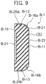
- FIG. 8 is a perspective view showing the connector B-1 of FIG. 7 .
- FIG. 9 is a cross-sectional view of the connector B-1 of FIG. 8 taken along line V-V. The particulars of the connector B-1 of FIGs. 6 to 9 are described in JP 2009-176474 A . In the connector B-1 of FIGs.
- FIG. 10 is a diagram showing still another example of configuration of a connector to be used under the condition of load as low as about 0.1 N.
- a connector C-11 is accommodated in a socket C-1.
- This diagram is a perspective view showing, in an exploded state, the socket C-1 as well as a first connection object C-51 and a second connection object C-61 that are connected by the socket C-1.
- FIG. 11 is an enlarged perspective view of the connector C-11 shown in FIG. 10 .
- FIG. 12 is an enlarged cross-sectional view of a part of the connector C-11 shown in FIG. 11 .
- the particulars of the connector C-11 of FIGs. 10 to 12 are described in JP 2008-108453 A . In C-1 and the connector C-11 of FIGs.
- FIG. 13 is an exploded perspective view showing still another example of configuration of a connector to be used under the condition of load as low as about 0.1 N.
- FIG. 14 is a perspective view of a connector D-1 for flexible printed circuit (FPC) connection shown in FIG. 13 .
- FIG. 15 is a plan view of an FPC D-80 inserted into the connector D-1 of FIG. 13 .
- FIG. 16 is a cross-sectional view of the connector D-1 of FIG. 13 taken along line A-A.
- the particulars of the connector D-1 for flexible printed circuit (FPC) connection of FIGs. 13 to 16 are described in JP 2015-204227 A . In the connector D-1 of FIGs.
- D-10 represents a housing, D-11 a bottom part, D-12 a lateral wall part, D-13 a rear wall, D-14 a through-hole, D-15 a front end part, D-16 a guide part, D-17 a stop part, D-20 a contact, D-21 a terminal part, D-23 a fixing part, D-24 a connection part, D-30 a contact, D-31 a terminal part, D-33 an extension part, D-34 a folding part, D-35 a connection part, D-40 a cover, D-41 a locking part, D-42 an abutment part, D-50 an opening, D-60 an insertion hole, D-70 a projection, D-71 a ridge part, D-72 a slope part, and D-73 a slope part.
- D-81 represents a connection part
- D-82 a connection part
- D-83 an insulating part
- D-84 an engagement recess part.
- metals may be indicated by element symbols instead of names, for example Ag for silver and Cu for copper.
- Silver particles 1 (flake shape): Silbest reduction silver G-1 (manufactured by Tokuriki Honten, Co., Ltd.) was pulverized using a ball mill and classified with Turbo Classifier (manufactured by Nisshin Engineering Inc.).
- Silver particles 3 (flake shape): YFS-02 (commercial name) (manufactured by YAMAKIN Co., Ltd.)
- Silver particles 4 (spheroidal shape): Silbest reduction silver G-1 (commercial name) (manufactured by Tokuriki Honten, Co., Ltd.)
- the aspect ratio of silver particles was calculated by observing the silver particles with an electron microscope (JSM-6301F, manufactured by JEOL Ltd.) in a field of view at 2,000X to 50,000X and analyzing the particle shape.
- Silver particles 1 have an average aspect ratio of 50 (average maximum length a 2 : 5.1 pm); Silver particles 2 have an average aspect ratio of 30 (average maximum length a 2 : 4.8 um); and Silver particles 3 have an average aspect ratio of 15 (average maximum length a 2 : 3.9 um).
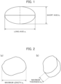
- Silver particles 4 having a spheroidal shape For Silver particles 4 having a spheroidal shape (see FIG. 1 ), the length a 1 of the long axis and the length b 1 of the short axis passing the middle of the long axis were measured for each of 50 particles in the observation field of view, the ratio between a 1 and b 1 (a 1 /b 1 ) was calculated as the aspect ratio, and the median (the value of D(50)) of the distribution of such ratios was taken as the average aspect ratio. Silver particles 4 have an average aspect ratio of 1 (average length a 1 of long axis: 4.2 um). Thus, the particle shape of Silver particles 4 is a perfect sphere.
- compositions were prepared by mixing the above components in proportions listed in Table 1 shown below.
- Each composition contains a specified oil and metal particles that interact with each other and form the specified metal particles described above, while part of the specified oil remains as is in the composition.
- the obtained Compositions 1 to 4 contained specified oil and specified metal particles.
- the obtained compositions 1 to 4 each contain silver particles as shown in Table 2.
- Component Composition (unit: mass%) 1 2 3 4 Silver particles 1 1 1 1 1 1H,1H-perfluoro(2,5,8,11,14-pentamethyl-3,6,9,12,15-oxaoctadecan-1-ol) 2 2 2 2 2 Vertrel XF 97 97 97 97 Total 100 100 100 100 [Table 2] Component Composition 1 2 3 4 Silver particles (type) 1 2 3 4 Silver particles (average aspect ratio) 50 30 15 1
- the probes and the plates were coated by dipping with each type of compositions. After the coating, the probes and the plates were let dry naturally at normal temperature for one hour, and thus probes having a predetermined coating and plates having a predetermined coating were prepared.
- Friction and wear tester with simultaneous measurement of electrical contact resistance FPR-2300 (RHESCA Co., Ltd.) 0024
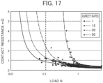
- the W-R curves in FIG. 17 reveal that the contact resistance decreases at a low load as the aspect ratio is closer to 1. Further, it is revealed that when the aspect ratio is 30 or less, the contact resistance can achieve a value of less than 5 mQ even at a load lower than 0.1 N.
Landscapes
- Chemical & Material Sciences (AREA)
- Engineering & Computer Science (AREA)
- Organic Chemistry (AREA)
- Materials Engineering (AREA)
- Chemical Kinetics & Catalysis (AREA)
- Mechanical Engineering (AREA)
- Metallurgy (AREA)
- General Chemical & Material Sciences (AREA)
- Physics & Mathematics (AREA)
- Dispersion Chemistry (AREA)
- Spectroscopy & Molecular Physics (AREA)
- Composite Materials (AREA)
- Oil, Petroleum & Natural Gas (AREA)
- Nanotechnology (AREA)
- Lubricants (AREA)
- Electroplating Methods And Accessories (AREA)
- Other Surface Treatments For Metallic Materials (AREA)
- Manufacturing Of Electrical Connectors (AREA)
Claims (6)
- Kontaktelement (10), aufweisend:eine Metallbasis (11); undeine Beschichtung (12), die auf mindestens einem Teil der Metallbasis (11) angeordnet ist,dadurch gekennzeichnet, dass die Beschichtung (12) fluoriertes Öl mit einer polaren Gruppe und Metallteilchen (14), die mit einer Verbindung auf Fluorbasis (15) mit einer polaren Gruppe oberflächenbehandelt sind, enthält,die Metallteilchen (14) ein durchschnittliches Aspektverhältnis (Länge der langen Achse/Länge der kurzen Achse) von 30 oder weniger haben,die Metallteilchen (14) eine durchschnittliche Primärteilchengröße von 0,2 um bis 10,0 µm haben, unddie durchschnittliche Primärteilchengröße der Metallteilchen (14) ein arithmetischer Durchschnittswert ist, der durch Messen der Durchmesser von 20 oder mehr Metallteilchen (14) unter Verwendung eines Elektronenmikroskops erhalten wird.
- Kontaktelement nach Anspruch 1, wobei ein Metall der Metallbasis (11) identisch mit dem der Metallpartikel (14) ist.
- Kontaktelement nach Anspruch 1 oder 2, wobei die polare Gruppe eine Hydroxylgruppe ist.
- Verbinder (A-10, B-1, C-11, D-1), der das Kontaktelement (10) nach einem der Ansprüche 1 bis 3 aufweist.
- Verwendung einer Zusammensetzung zur Bildung einer Beschichtung (12) eines Kontaktelements (10), das eine Metallbasis (11) und die auf mindestens einem Teil der Metallbasis (11) angeordnete Beschichtung (12) einschließt, wobei die Zusammensetzung aufweist: fluoriertes Öl mit einer polaren Gruppe; und Metallteilchen (14), die mit einer Verbindung (15) mit einer Verbindung auf Fluorbasis mit einer polaren Gruppe oberflächenbehandelt sind, wobei die Metallteilchen (14) ein durchschnittliches Aspektverhältnis (Länge der langen Achse/Länge der kurzen Achse) von 30 oder weniger aufweisen,die Metallteilchen (14) eine durchschnittliche Primärteilchengröße von 0,2 um bis 10,0 µm haben undwobei die durchschnittliche Primärteilchengröße der Metallteilchen (14) ein arithmetischer Durchschnittswert ist, der durch Messung der Durchmesser von 20 oder mehr Metallteilchen (14) unter Verwendung eines Elektronenmikroskops erhalten wird.
- Verfahren zur Herstellung des Kontaktelements (10) nach einem der Ansprüche 1 bis 3, aufweisend den Schritt des Bildens der Beschichtung (12) durch Aufbringen einer Zusammensetzung auf die Metallbasis (11),wobei die Zusammensetzung aufweist: fluoriertes Öl mit einer polaren Gruppe; und Metallteilchen (14), die mit einer Verbindung (15) auf Fluorbasis mit einer polaren Gruppe oberflächenbehandelt sind, wobei die Metallteilchen (14) ein durchschnittliches Aspektverhältnis (Länge der langen Achse/Länge der kurzen Achse) von 30 oder weniger aufweisen,die Metallteilchen (14) eine durchschnittliche Primärteilchengröße von 0,2 um bis 10,0 µm haben unddie durchschnittliche Primärteilchengröße der Metallteilchen (14) ein arithmetischer Durchschnittswert ist, der durch Messung der Durchmesser von 20 oder mehr Metallteilchen (14) unter Verwendung eines Elektronenmikroskops erhalten wird.
Applications Claiming Priority (3)
| Application Number | Priority Date | Filing Date | Title |
|---|---|---|---|
| JP2020057814 | 2020-03-27 | ||
| JP2021009500A JP6872088B1 (ja) | 2020-03-27 | 2021-01-25 | 接点部材、コネクタ、組成物、接点部材の製造方法 |
| PCT/JP2021/006325 WO2021192759A1 (ja) | 2020-03-27 | 2021-02-19 | 接点部材、コネクタ、組成物、接点部材の製造方法 |
Publications (3)
| Publication Number | Publication Date |
|---|---|
| EP4131306A1 EP4131306A1 (de) | 2023-02-08 |
| EP4131306A4 EP4131306A4 (de) | 2023-09-06 |
| EP4131306B1 true EP4131306B1 (de) | 2024-07-10 |
Family
ID=75896300
Family Applications (2)
| Application Number | Title | Priority Date | Filing Date |
|---|---|---|---|
| EP21776627.8A Active EP4131307B1 (de) | 2020-03-27 | 2021-02-19 | Kontaktelement, verbinder, zusammensetzung und verfahren zur herstellung eines kontaktelements |
| EP21774380.6A Active EP4131306B1 (de) | 2020-03-27 | 2021-02-19 | Kontaktelement, verbinder, zusammensetzung und verfahren zur herstellung eines kontaktelements |
Family Applications Before (1)
| Application Number | Title | Priority Date | Filing Date |
|---|---|---|---|
| EP21776627.8A Active EP4131307B1 (de) | 2020-03-27 | 2021-02-19 | Kontaktelement, verbinder, zusammensetzung und verfahren zur herstellung eines kontaktelements |
Country Status (5)
| Country | Link |
|---|---|
| US (2) | US12355172B2 (de) |
| EP (2) | EP4131307B1 (de) |
| JP (2) | JP6872089B1 (de) |
| CN (2) | CN115104227A (de) |
| WO (2) | WO2021192759A1 (de) |
Families Citing this family (1)
| Publication number | Priority date | Publication date | Assignee | Title |
|---|---|---|---|---|
| DE102022118078A1 (de) * | 2022-07-19 | 2024-01-25 | Weidmüller Interface GmbH & Co. KG | Anordnung aus zumindest einer Klemmfeder und eine Haltefeder und eine Federkraftklemme für Leiter |
Family Cites Families (21)
| Publication number | Priority date | Publication date | Assignee | Title |
|---|---|---|---|---|
| JPH10223290A (ja) * | 1997-02-07 | 1998-08-21 | Sumitomo Wiring Syst Ltd | 接続用端子 |
| JP3948642B2 (ja) * | 1998-08-21 | 2007-07-25 | 信越化学工業株式会社 | 熱伝導性グリース組成物及びそれを使用した半導体装置 |
| US7004799B2 (en) * | 2003-01-21 | 2006-02-28 | Tyco Electronics Corporation | High temperature inhibitor material and methods of making and using the same |
| JP4083084B2 (ja) * | 2003-06-24 | 2008-04-30 | 株式会社神戸製鋼所 | コネクタ接点材料および多極端子 |
| JP4348288B2 (ja) | 2004-12-20 | 2009-10-21 | 株式会社神戸製鋼所 | コネクタ接点材料 |
| JP4246707B2 (ja) * | 2005-01-27 | 2009-04-02 | 日本航空電子工業株式会社 | 潤滑剤 |
| JP4286278B2 (ja) | 2006-10-23 | 2009-06-24 | 日本航空電子工業株式会社 | ソケット |
| WO2009005041A1 (ja) * | 2007-06-29 | 2009-01-08 | The Furukawa Electric Co., Ltd. | 耐フレッティング性コネクタおよびその製造方法 |
| JP2009176474A (ja) | 2008-01-22 | 2009-08-06 | Japan Aviation Electronics Industry Ltd | コネクタ |
| JP2012018869A (ja) | 2010-07-09 | 2012-01-26 | Tyco Electronics Japan Kk | 電気コンタクト |
| JP2012099398A (ja) * | 2010-11-04 | 2012-05-24 | Auto Network Gijutsu Kenkyusho:Kk | 電気接点及びコネクタ端子 |
| JP2012172713A (ja) * | 2011-02-18 | 2012-09-10 | Nsk Ltd | 転がり軸受 |
| JP5732327B2 (ja) | 2011-06-23 | 2015-06-10 | 日本航空電子工業株式会社 | 電気コンタクト、及び、電気コネクタ |
| CN103620447B (zh) * | 2011-07-11 | 2016-12-21 | 东丽株式会社 | 成型材料、涂料组合物及成型材料的制造方法 |
| JP6150370B2 (ja) | 2012-04-06 | 2017-06-21 | 日本航空電子工業株式会社 | コネクタ |
| JP5464284B1 (ja) | 2013-01-10 | 2014-04-09 | 株式会社オートネットワーク技術研究所 | コネクタ端子及びコネクタ端子の製造方法 |
| JP5624191B2 (ja) | 2013-08-27 | 2014-11-12 | 日本航空電子工業株式会社 | コネクタ |
| JP6187374B2 (ja) | 2014-04-15 | 2017-08-30 | Smk株式会社 | フレキシブル基板接続用コネクタ |
| JP6806546B2 (ja) * | 2016-11-30 | 2021-01-06 | 日本航空電子工業株式会社 | 超撥水表面構造 |
| JP6410163B1 (ja) * | 2017-06-22 | 2018-10-24 | 日立金属株式会社 | 端子付き電線 |
| JP6892120B2 (ja) * | 2017-11-28 | 2021-06-18 | 協立化学産業株式会社 | 被覆金属粒子、導電性組成物、導電体、接合用積層体、回路形成物及び焼結体の製造方法 |
-
2021
- 2021-01-25 JP JP2021009589A patent/JP6872089B1/ja active Active
- 2021-01-25 JP JP2021009500A patent/JP6872088B1/ja active Active
- 2021-02-19 CN CN202180014671.1A patent/CN115104227A/zh active Pending
- 2021-02-19 WO PCT/JP2021/006325 patent/WO2021192759A1/ja not_active Ceased
- 2021-02-19 EP EP21776627.8A patent/EP4131307B1/de active Active
- 2021-02-19 CN CN202180014655.2A patent/CN115088138A/zh active Pending
- 2021-02-19 WO PCT/JP2021/006313 patent/WO2021192757A1/ja not_active Ceased
- 2021-02-19 EP EP21774380.6A patent/EP4131306B1/de active Active
-
2022
- 2022-08-25 US US17/895,614 patent/US12355172B2/en active Active
- 2022-08-25 US US17/895,695 patent/US12362510B2/en active Active
Also Published As
| Publication number | Publication date |
|---|---|
| EP4131307A4 (de) | 2023-09-06 |
| JP6872089B1 (ja) | 2021-05-19 |
| US20220416460A1 (en) | 2022-12-29 |
| CN115088138A (zh) | 2022-09-20 |
| EP4131306A1 (de) | 2023-02-08 |
| JP2021155706A (ja) | 2021-10-07 |
| WO2021192759A1 (ja) | 2021-09-30 |
| EP4131307A1 (de) | 2023-02-08 |
| EP4131307B1 (de) | 2024-07-17 |
| US12355172B2 (en) | 2025-07-08 |
| JP6872088B1 (ja) | 2021-05-19 |
| US12362510B2 (en) | 2025-07-15 |
| US20230006386A1 (en) | 2023-01-05 |
| WO2021192757A1 (ja) | 2021-09-30 |
| JP2021155707A (ja) | 2021-10-07 |
| EP4131306A4 (de) | 2023-09-06 |
| CN115104227A (zh) | 2022-09-23 |
Similar Documents
| Publication | Publication Date | Title |
|---|---|---|
| KR102058344B1 (ko) | 전자 부품용 금속 재료 및 그 제조 방법, 그것을 사용한 커넥터 단자, 커넥터 및 전자 부품 | |
| JP6224090B2 (ja) | 電子部品 | |
| CN104471113B (zh) | 电子部件用金属材料及其制造方法、使用其的连接器端子、连接器及电子部件 | |
| JP2014029007A (ja) | 電子部品用金属材料及びその製造方法、それを用いたコネクタ端子、コネクタ及び電子部品 | |
| EP3575446B1 (de) | Oberflächenbehandeltes plattiertes material, verbinderanschluss, verbinder, ffc-anschluss, ffc, fpc und elektronisches bauelement | |
| JP4348288B2 (ja) | コネクタ接点材料 | |
| EP4131306B1 (de) | Kontaktelement, verbinder, zusammensetzung und verfahren zur herstellung eines kontaktelements | |
| CN103178370A (zh) | 部件 | |
| Noël et al. | Influence of contact interface composition on the electrical and tribological properties of nickel electrodeposits during fretting tests | |
| Antler | Fretting corrosion of solder-coated electrical contacts | |
| JP4083084B2 (ja) | コネクタ接点材料および多極端子 | |
| KR20060101275A (ko) | 저마찰 전기 접촉부 | |
| US7104850B2 (en) | Low insertion-force connector terminal, method of producing the same and substrate for the same | |
| TWI905580B (zh) | 金屬材料及滑動零件 | |
| JP2006086113A (ja) | 低挿入力コネクタ端子、その製造方法、及び、低挿入力コネクタ端子用基板 | |
| JP2011210479A (ja) | 嵌合型端子用Snめっき付き銅又は銅合金板材 | |
| JP2015045046A (ja) | 電子部品用金属材料及びその製造方法、それを用いたコネクタ端子、コネクタ及び電子部品 |
Legal Events
| Date | Code | Title | Description |
|---|---|---|---|
| STAA | Information on the status of an ep patent application or granted ep patent |
Free format text: STATUS: THE INTERNATIONAL PUBLICATION HAS BEEN MADE |
|
| PUAI | Public reference made under article 153(3) epc to a published international application that has entered the european phase |
Free format text: ORIGINAL CODE: 0009012 |
|
| STAA | Information on the status of an ep patent application or granted ep patent |
Free format text: STATUS: REQUEST FOR EXAMINATION WAS MADE |
|
| 17P | Request for examination filed |
Effective date: 20220817 |
|
| AK | Designated contracting states |
Kind code of ref document: A1 Designated state(s): AL AT BE BG CH CY CZ DE DK EE ES FI FR GB GR HR HU IE IS IT LI LT LU LV MC MK MT NL NO PL PT RO RS SE SI SK SM TR |
|
| DAV | Request for validation of the european patent (deleted) | ||
| DAX | Request for extension of the european patent (deleted) | ||
| A4 | Supplementary search report drawn up and despatched |
Effective date: 20230803 |
|
| RIC1 | Information provided on ipc code assigned before grant |
Ipc: C23C 24/10 20060101ALN20230728BHEP Ipc: C22C 1/04 20230101ALN20230728BHEP Ipc: C10N 80/00 20060101ALN20230728BHEP Ipc: C10N 50/00 20060101ALN20230728BHEP Ipc: C10N 40/14 20060101ALN20230728BHEP Ipc: C10N 30/00 20060101ALN20230728BHEP Ipc: C10N 30/06 20060101ALN20230728BHEP Ipc: C10N 20/00 20060101ALN20230728BHEP Ipc: C10N 20/06 20060101ALN20230728BHEP Ipc: C10N 70/00 20060101ALN20230728BHEP Ipc: C10N 50/02 20060101ALN20230728BHEP Ipc: C10N 10/02 20060101ALN20230728BHEP Ipc: H01R 12/73 20110101ALI20230728BHEP Ipc: H01B 1/22 20060101ALI20230728BHEP Ipc: B22F 1/102 20220101ALI20230728BHEP Ipc: B22F 1/068 20220101ALI20230728BHEP Ipc: C10M 169/04 20060101ALI20230728BHEP Ipc: H01R 13/03 20060101ALI20230728BHEP Ipc: H01R 43/16 20060101ALI20230728BHEP Ipc: C23C 26/00 20060101ALI20230728BHEP Ipc: H01H 1/025 20060101AFI20230728BHEP |
|
| GRAP | Despatch of communication of intention to grant a patent |
Free format text: ORIGINAL CODE: EPIDOSNIGR1 |
|
| STAA | Information on the status of an ep patent application or granted ep patent |
Free format text: STATUS: GRANT OF PATENT IS INTENDED |
|
| RIC1 | Information provided on ipc code assigned before grant |
Ipc: C23C 24/10 20060101ALN20240308BHEP Ipc: C22C 1/04 20060101ALN20240308BHEP Ipc: C10N 80/00 20060101ALN20240308BHEP Ipc: C10N 50/00 20060101ALN20240308BHEP Ipc: C10N 40/14 20060101ALN20240308BHEP Ipc: C10N 30/00 20060101ALN20240308BHEP Ipc: C10N 30/06 20060101ALN20240308BHEP Ipc: C10N 20/00 20060101ALN20240308BHEP Ipc: C10N 20/06 20060101ALN20240308BHEP Ipc: C10N 70/00 20060101ALN20240308BHEP Ipc: C10N 50/02 20060101ALN20240308BHEP Ipc: C10N 10/02 20060101ALN20240308BHEP Ipc: H01R 12/73 20110101ALI20240308BHEP Ipc: H01B 1/22 20060101ALI20240308BHEP Ipc: B22F 1/102 20220101ALI20240308BHEP Ipc: B22F 1/068 20220101ALI20240308BHEP Ipc: C10M 169/04 20060101ALI20240308BHEP Ipc: H01R 13/03 20060101ALI20240308BHEP Ipc: H01R 43/16 20060101ALI20240308BHEP Ipc: C23C 26/00 20060101ALI20240308BHEP Ipc: H01H 1/025 20060101AFI20240308BHEP |
|
| INTG | Intention to grant announced |
Effective date: 20240327 |
|
| RAP3 | Party data changed (applicant data changed or rights of an application transferred) |
Owner name: JAPAN AVIATION ELECTRONICS INDUSTRY, LIMITED |
|
| GRAS | Grant fee paid |
Free format text: ORIGINAL CODE: EPIDOSNIGR3 |
|
| GRAA | (expected) grant |
Free format text: ORIGINAL CODE: 0009210 |
|
| STAA | Information on the status of an ep patent application or granted ep patent |
Free format text: STATUS: THE PATENT HAS BEEN GRANTED |
|
| AK | Designated contracting states |
Kind code of ref document: B1 Designated state(s): AL AT BE BG CH CY CZ DE DK EE ES FI FR GB GR HR HU IE IS IT LI LT LU LV MC MK MT NL NO PL PT RO RS SE SI SK SM TR |
|
| REG | Reference to a national code |
Ref country code: CH Ref legal event code: EP |
|
| REG | Reference to a national code |
Ref country code: DE Ref legal event code: R096 Ref document number: 602021015581 Country of ref document: DE |
|
| REG | Reference to a national code |
Ref country code: LT Ref legal event code: MG9D |
|
| REG | Reference to a national code |
Ref country code: NL Ref legal event code: MP Effective date: 20240710 |
|
| PG25 | Lapsed in a contracting state [announced via postgrant information from national office to epo] |
Ref country code: PT Free format text: LAPSE BECAUSE OF FAILURE TO SUBMIT A TRANSLATION OF THE DESCRIPTION OR TO PAY THE FEE WITHIN THE PRESCRIBED TIME-LIMIT Effective date: 20241111 |
|
| REG | Reference to a national code |
Ref country code: AT Ref legal event code: MK05 Ref document number: 1702799 Country of ref document: AT Kind code of ref document: T Effective date: 20240710 |
|
| PG25 | Lapsed in a contracting state [announced via postgrant information from national office to epo] |
Ref country code: NL Free format text: LAPSE BECAUSE OF FAILURE TO SUBMIT A TRANSLATION OF THE DESCRIPTION OR TO PAY THE FEE WITHIN THE PRESCRIBED TIME-LIMIT Effective date: 20240710 |
|
| PG25 | Lapsed in a contracting state [announced via postgrant information from national office to epo] |
Ref country code: PT Free format text: LAPSE BECAUSE OF FAILURE TO SUBMIT A TRANSLATION OF THE DESCRIPTION OR TO PAY THE FEE WITHIN THE PRESCRIBED TIME-LIMIT Effective date: 20241111 Ref country code: NL Free format text: LAPSE BECAUSE OF FAILURE TO SUBMIT A TRANSLATION OF THE DESCRIPTION OR TO PAY THE FEE WITHIN THE PRESCRIBED TIME-LIMIT Effective date: 20240710 |
|
| PG25 | Lapsed in a contracting state [announced via postgrant information from national office to epo] |
Ref country code: NO Free format text: LAPSE BECAUSE OF FAILURE TO SUBMIT A TRANSLATION OF THE DESCRIPTION OR TO PAY THE FEE WITHIN THE PRESCRIBED TIME-LIMIT Effective date: 20241010 |
|
| PG25 | Lapsed in a contracting state [announced via postgrant information from national office to epo] |
Ref country code: GR Free format text: LAPSE BECAUSE OF FAILURE TO SUBMIT A TRANSLATION OF THE DESCRIPTION OR TO PAY THE FEE WITHIN THE PRESCRIBED TIME-LIMIT Effective date: 20241011 Ref country code: FI Free format text: LAPSE BECAUSE OF FAILURE TO SUBMIT A TRANSLATION OF THE DESCRIPTION OR TO PAY THE FEE WITHIN THE PRESCRIBED TIME-LIMIT Effective date: 20240710 Ref country code: PL Free format text: LAPSE BECAUSE OF FAILURE TO SUBMIT A TRANSLATION OF THE DESCRIPTION OR TO PAY THE FEE WITHIN THE PRESCRIBED TIME-LIMIT Effective date: 20240710 |
|
| PG25 | Lapsed in a contracting state [announced via postgrant information from national office to epo] |
Ref country code: BG Free format text: LAPSE BECAUSE OF FAILURE TO SUBMIT A TRANSLATION OF THE DESCRIPTION OR TO PAY THE FEE WITHIN THE PRESCRIBED TIME-LIMIT Effective date: 20240710 |
|
| PG25 | Lapsed in a contracting state [announced via postgrant information from national office to epo] |
Ref country code: LV Free format text: LAPSE BECAUSE OF FAILURE TO SUBMIT A TRANSLATION OF THE DESCRIPTION OR TO PAY THE FEE WITHIN THE PRESCRIBED TIME-LIMIT Effective date: 20240710 |
|
| PG25 | Lapsed in a contracting state [announced via postgrant information from national office to epo] |
Ref country code: IS Free format text: LAPSE BECAUSE OF FAILURE TO SUBMIT A TRANSLATION OF THE DESCRIPTION OR TO PAY THE FEE WITHIN THE PRESCRIBED TIME-LIMIT Effective date: 20241110 Ref country code: AT Free format text: LAPSE BECAUSE OF FAILURE TO SUBMIT A TRANSLATION OF THE DESCRIPTION OR TO PAY THE FEE WITHIN THE PRESCRIBED TIME-LIMIT Effective date: 20240710 |
|
| PG25 | Lapsed in a contracting state [announced via postgrant information from national office to epo] |
Ref country code: HR Free format text: LAPSE BECAUSE OF FAILURE TO SUBMIT A TRANSLATION OF THE DESCRIPTION OR TO PAY THE FEE WITHIN THE PRESCRIBED TIME-LIMIT Effective date: 20240710 |
|
| PG25 | Lapsed in a contracting state [announced via postgrant information from national office to epo] |
Ref country code: ES Free format text: LAPSE BECAUSE OF FAILURE TO SUBMIT A TRANSLATION OF THE DESCRIPTION OR TO PAY THE FEE WITHIN THE PRESCRIBED TIME-LIMIT Effective date: 20240710 Ref country code: RS Free format text: LAPSE BECAUSE OF FAILURE TO SUBMIT A TRANSLATION OF THE DESCRIPTION OR TO PAY THE FEE WITHIN THE PRESCRIBED TIME-LIMIT Effective date: 20241010 |
|
| PG25 | Lapsed in a contracting state [announced via postgrant information from national office to epo] |
Ref country code: RS Free format text: LAPSE BECAUSE OF FAILURE TO SUBMIT A TRANSLATION OF THE DESCRIPTION OR TO PAY THE FEE WITHIN THE PRESCRIBED TIME-LIMIT Effective date: 20241010 Ref country code: PL Free format text: LAPSE BECAUSE OF FAILURE TO SUBMIT A TRANSLATION OF THE DESCRIPTION OR TO PAY THE FEE WITHIN THE PRESCRIBED TIME-LIMIT Effective date: 20240710 Ref country code: NO Free format text: LAPSE BECAUSE OF FAILURE TO SUBMIT A TRANSLATION OF THE DESCRIPTION OR TO PAY THE FEE WITHIN THE PRESCRIBED TIME-LIMIT Effective date: 20241010 Ref country code: LV Free format text: LAPSE BECAUSE OF FAILURE TO SUBMIT A TRANSLATION OF THE DESCRIPTION OR TO PAY THE FEE WITHIN THE PRESCRIBED TIME-LIMIT Effective date: 20240710 Ref country code: IS Free format text: LAPSE BECAUSE OF FAILURE TO SUBMIT A TRANSLATION OF THE DESCRIPTION OR TO PAY THE FEE WITHIN THE PRESCRIBED TIME-LIMIT Effective date: 20241110 Ref country code: HR Free format text: LAPSE BECAUSE OF FAILURE TO SUBMIT A TRANSLATION OF THE DESCRIPTION OR TO PAY THE FEE WITHIN THE PRESCRIBED TIME-LIMIT Effective date: 20240710 Ref country code: GR Free format text: LAPSE BECAUSE OF FAILURE TO SUBMIT A TRANSLATION OF THE DESCRIPTION OR TO PAY THE FEE WITHIN THE PRESCRIBED TIME-LIMIT Effective date: 20241011 Ref country code: FI Free format text: LAPSE BECAUSE OF FAILURE TO SUBMIT A TRANSLATION OF THE DESCRIPTION OR TO PAY THE FEE WITHIN THE PRESCRIBED TIME-LIMIT Effective date: 20240710 Ref country code: ES Free format text: LAPSE BECAUSE OF FAILURE TO SUBMIT A TRANSLATION OF THE DESCRIPTION OR TO PAY THE FEE WITHIN THE PRESCRIBED TIME-LIMIT Effective date: 20240710 Ref country code: BG Free format text: LAPSE BECAUSE OF FAILURE TO SUBMIT A TRANSLATION OF THE DESCRIPTION OR TO PAY THE FEE WITHIN THE PRESCRIBED TIME-LIMIT Effective date: 20240710 Ref country code: AT Free format text: LAPSE BECAUSE OF FAILURE TO SUBMIT A TRANSLATION OF THE DESCRIPTION OR TO PAY THE FEE WITHIN THE PRESCRIBED TIME-LIMIT Effective date: 20240710 |
|
| PGFP | Annual fee paid to national office [announced via postgrant information from national office to epo] |
Ref country code: DE Payment date: 20250212 Year of fee payment: 5 |
|
| REG | Reference to a national code |
Ref country code: DE Ref legal event code: R097 Ref document number: 602021015581 Country of ref document: DE |
|
| PG25 | Lapsed in a contracting state [announced via postgrant information from national office to epo] |
Ref country code: SM Free format text: LAPSE BECAUSE OF FAILURE TO SUBMIT A TRANSLATION OF THE DESCRIPTION OR TO PAY THE FEE WITHIN THE PRESCRIBED TIME-LIMIT Effective date: 20240710 Ref country code: DK Free format text: LAPSE BECAUSE OF FAILURE TO SUBMIT A TRANSLATION OF THE DESCRIPTION OR TO PAY THE FEE WITHIN THE PRESCRIBED TIME-LIMIT Effective date: 20240710 Ref country code: RO Free format text: LAPSE BECAUSE OF FAILURE TO SUBMIT A TRANSLATION OF THE DESCRIPTION OR TO PAY THE FEE WITHIN THE PRESCRIBED TIME-LIMIT Effective date: 20240710 |
|
| PG25 | Lapsed in a contracting state [announced via postgrant information from national office to epo] |
Ref country code: EE Free format text: LAPSE BECAUSE OF FAILURE TO SUBMIT A TRANSLATION OF THE DESCRIPTION OR TO PAY THE FEE WITHIN THE PRESCRIBED TIME-LIMIT Effective date: 20240710 |
|
| PG25 | Lapsed in a contracting state [announced via postgrant information from national office to epo] |
Ref country code: CZ Free format text: LAPSE BECAUSE OF FAILURE TO SUBMIT A TRANSLATION OF THE DESCRIPTION OR TO PAY THE FEE WITHIN THE PRESCRIBED TIME-LIMIT Effective date: 20240710 |
|
| PG25 | Lapsed in a contracting state [announced via postgrant information from national office to epo] |
Ref country code: IT Free format text: LAPSE BECAUSE OF FAILURE TO SUBMIT A TRANSLATION OF THE DESCRIPTION OR TO PAY THE FEE WITHIN THE PRESCRIBED TIME-LIMIT Effective date: 20240710 Ref country code: SK Free format text: LAPSE BECAUSE OF FAILURE TO SUBMIT A TRANSLATION OF THE DESCRIPTION OR TO PAY THE FEE WITHIN THE PRESCRIBED TIME-LIMIT Effective date: 20240710 |
|
| PLBE | No opposition filed within time limit |
Free format text: ORIGINAL CODE: 0009261 |
|
| STAA | Information on the status of an ep patent application or granted ep patent |
Free format text: STATUS: NO OPPOSITION FILED WITHIN TIME LIMIT |
|
| 26N | No opposition filed |
Effective date: 20250411 |
|
| PG25 | Lapsed in a contracting state [announced via postgrant information from national office to epo] |
Ref country code: SE Free format text: LAPSE BECAUSE OF FAILURE TO SUBMIT A TRANSLATION OF THE DESCRIPTION OR TO PAY THE FEE WITHIN THE PRESCRIBED TIME-LIMIT Effective date: 20240710 |
|
| PG25 | Lapsed in a contracting state [announced via postgrant information from national office to epo] |
Ref country code: MC Free format text: LAPSE BECAUSE OF FAILURE TO SUBMIT A TRANSLATION OF THE DESCRIPTION OR TO PAY THE FEE WITHIN THE PRESCRIBED TIME-LIMIT Effective date: 20240710 |
|
| REG | Reference to a national code |
Ref country code: CH Ref legal event code: PL |
|
| PG25 | Lapsed in a contracting state [announced via postgrant information from national office to epo] |
Ref country code: LU Free format text: LAPSE BECAUSE OF NON-PAYMENT OF DUE FEES Effective date: 20250219 |
|
| PG25 | Lapsed in a contracting state [announced via postgrant information from national office to epo] |
Ref country code: CH Free format text: LAPSE BECAUSE OF NON-PAYMENT OF DUE FEES Effective date: 20250228 |
|
| GBPC | Gb: european patent ceased through non-payment of renewal fee |
Effective date: 20250219 |
|
| REG | Reference to a national code |
Ref country code: BE Ref legal event code: MM Effective date: 20250228 |
|
| PG25 | Lapsed in a contracting state [announced via postgrant information from national office to epo] |
Ref country code: GB Free format text: LAPSE BECAUSE OF NON-PAYMENT OF DUE FEES Effective date: 20250219 |
|
| PGFP | Annual fee paid to national office [announced via postgrant information from national office to epo] |
Ref country code: FR Payment date: 20251231 Year of fee payment: 6 |
|
| PG25 | Lapsed in a contracting state [announced via postgrant information from national office to epo] |
Ref country code: BE Free format text: LAPSE BECAUSE OF NON-PAYMENT OF DUE FEES Effective date: 20250228 |
|
| PG25 | Lapsed in a contracting state [announced via postgrant information from national office to epo] |
Ref country code: IE Free format text: LAPSE BECAUSE OF NON-PAYMENT OF DUE FEES Effective date: 20250219 |