EP4130918A1 - Traveling vehicle system - Google Patents
Traveling vehicle system Download PDFInfo
- Publication number
- EP4130918A1 EP4130918A1 EP21775864.8A EP21775864A EP4130918A1 EP 4130918 A1 EP4130918 A1 EP 4130918A1 EP 21775864 A EP21775864 A EP 21775864A EP 4130918 A1 EP4130918 A1 EP 4130918A1
- Authority
- EP
- European Patent Office
- Prior art keywords
- traveling vehicle
- traveling
- detector
- detectable part
- rail
- Prior art date
- Legal status (The legal status is an assumption and is not a legal conclusion. Google has not performed a legal analysis and makes no representation as to the accuracy of the status listed.)
- Granted
Links
Images




Classifications
-
- B—PERFORMING OPERATIONS; TRANSPORTING
- B65—CONVEYING; PACKING; STORING; HANDLING THIN OR FILAMENTARY MATERIAL
- B65G—TRANSPORT OR STORAGE DEVICES, e.g. CONVEYORS FOR LOADING OR TIPPING, SHOP CONVEYOR SYSTEMS OR PNEUMATIC TUBE CONVEYORS
- B65G1/00—Storing articles, individually or in orderly arrangement, in warehouses or magazines
- B65G1/02—Storage devices
- B65G1/04—Storage devices mechanical
- B65G1/0407—Storage devices mechanical using stacker cranes
- B65G1/0421—Storage devices mechanical using stacker cranes with control for stacker crane operations
-
- G—PHYSICS
- G05—CONTROLLING; REGULATING
- G05D—SYSTEMS FOR CONTROLLING OR REGULATING NON-ELECTRIC VARIABLES
- G05D1/00—Control of position, course, altitude or attitude of land, water, air or space vehicles, e.g. using automatic pilots
- G05D1/60—Intended control result
- G05D1/69—Coordinated control of the position or course of two or more vehicles
-
- B—PERFORMING OPERATIONS; TRANSPORTING
- B65—CONVEYING; PACKING; STORING; HANDLING THIN OR FILAMENTARY MATERIAL
- B65G—TRANSPORT OR STORAGE DEVICES, e.g. CONVEYORS FOR LOADING OR TIPPING, SHOP CONVEYOR SYSTEMS OR PNEUMATIC TUBE CONVEYORS
- B65G1/00—Storing articles, individually or in orderly arrangement, in warehouses or magazines
- B65G1/02—Storage devices
- B65G1/04—Storage devices mechanical
-
- B—PERFORMING OPERATIONS; TRANSPORTING
- B66—HOISTING; LIFTING; HAULING
- B66F—HOISTING, LIFTING, HAULING OR PUSHING, NOT OTHERWISE PROVIDED FOR, e.g. DEVICES WHICH APPLY A LIFTING OR PUSHING FORCE DIRECTLY TO THE SURFACE OF A LOAD
- B66F9/00—Devices for lifting or lowering bulky or heavy goods for loading or unloading purposes
- B66F9/06—Devices for lifting or lowering bulky or heavy goods for loading or unloading purposes movable, with their loads, on wheels or the like, e.g. fork-lift trucks
- B66F9/07—Floor-to-roof stacking devices, e.g. "stacker cranes", "retrievers"
-
- B—PERFORMING OPERATIONS; TRANSPORTING
- B65—CONVEYING; PACKING; STORING; HANDLING THIN OR FILAMENTARY MATERIAL
- B65G—TRANSPORT OR STORAGE DEVICES, e.g. CONVEYORS FOR LOADING OR TIPPING, SHOP CONVEYOR SYSTEMS OR PNEUMATIC TUBE CONVEYORS
- B65G1/00—Storing articles, individually or in orderly arrangement, in warehouses or magazines
- B65G1/02—Storage devices
- B65G1/04—Storage devices mechanical
- B65G1/0407—Storage devices mechanical using stacker cranes
-
- B—PERFORMING OPERATIONS; TRANSPORTING
- B65—CONVEYING; PACKING; STORING; HANDLING THIN OR FILAMENTARY MATERIAL
- B65G—TRANSPORT OR STORAGE DEVICES, e.g. CONVEYORS FOR LOADING OR TIPPING, SHOP CONVEYOR SYSTEMS OR PNEUMATIC TUBE CONVEYORS
- B65G1/00—Storing articles, individually or in orderly arrangement, in warehouses or magazines
- B65G1/02—Storage devices
- B65G1/04—Storage devices mechanical
- B65G1/137—Storage devices mechanical with arrangements or automatic control means for selecting which articles are to be removed
-
- G—PHYSICS
- G05—CONTROLLING; REGULATING
- G05D—SYSTEMS FOR CONTROLLING OR REGULATING NON-ELECTRIC VARIABLES
- G05D1/00—Control of position, course, altitude or attitude of land, water, air or space vehicles, e.g. using automatic pilots
- G05D1/60—Intended control result
- G05D1/646—Following a predefined trajectory, e.g. a line marked on the floor or a flight path
-
- G—PHYSICS
- G05—CONTROLLING; REGULATING
- G05D—SYSTEMS FOR CONTROLLING OR REGULATING NON-ELECTRIC VARIABLES
- G05D2107/00—Specific environments of the controlled vehicles
- G05D2107/70—Industrial sites, e.g. warehouses or factories
Definitions
- An aspect of the present invention relates to a traveling vehicle system.
- Patent Literature 1 discloses an automated warehouse in which two vehicles of a first traveling vehicle and a second traveling vehicle travel on a single traveling rail, and traveling areas in each of which the corresponding one of the two traveling vehicles travels and a shared area that both of the two traveling vehicles can enter are provided therein. In this shared area, in order to prevent one of the first traveling vehicle and the second traveling vehicle from entering the traveling area of the other of the first traveling vehicle and the second traveling vehicle, it is necessary to detect their own traveling positions.
- these traveling vehicles are provided with rotary encoders to detect their own traveling positions.
- the article storage facility in Patent Literature 1 is provided with a chain (detectable part) on the traveling rail, and each traveling vehicle travels with a sprocket of the corresponding rotary encoder (detector) meshing with the chain, and detects its own traveling position by detecting the rotation of the sprocket during traveling.
- Patent Literature 1 Japanese Patent No. 4089154
- traveling rail on which traveling vehicles travel as described above is installed at a site such as a factory, it is more preferable to connect a plurality of divided traveling rails rather than to install a single traveling rail, because a gap between the traveling rails can absorb errors between dimensions of the site where the traveling rails are installed and product dimensions.
- detectable parts such as chains extending in one direction along the traveling rail are installed with a gap formed therebetween in the traveling direction, each own position cannot be detected because the meshing with the corresponding rotary encoder disengages.
- the traveling rail on which the traveling vehicles travel is formed of a plurality of traveling rail members, certain measures are required for the first traveling vehicle and the second traveling vehicle to properly detect their own positions.
- the traveling vehicle system includes: a traveling rail including a first rail member and a second rail member extending horizontally; a first traveling vehicle and a second traveling vehicle configured to travel on the traveling rail; a first detectable part provided with the first rail member and extending along an extending direction of the traveling rail; a second detectable part provided with the second rail member and extending along the extending direction of the traveling rail; a first detector provided with the first traveling vehicle and configured to detect the first detectable part; and a second detector provided with the second traveling vehicle and configured to detect the second detectable part.
- a connecting portion in which the first rail member and the second rail member are connected with a gap therebetween or in a manner being in contact with each other is provided.
- the first detectable part is disposed at a position detectable by the first detector and the second detectable part is disposed at a position undetectable by the first detector when the first traveling vehicle is located in a first position being at an end of the first rail member closer to the connecting portion in the shared area.
- the second detectable part is disposed at a position detectable by the second detector and the first detectable part is disposed at a position undetectable by the second detector when the second traveling vehicle is located in a second position being at an end of the second rail member closer to the connecting portion in the shared area.
- the traveling rail is formed by the first rail member and the second rail member. This allows the gap to be formed between the first rail member and the second rail member in a manner adjusted to dimensions of the site when the traveling rail is disposed, and thus errors with respect to product dimensions can be absorbed. Furthermore, in this configuration, it is possible to detect whether the first traveling vehicle is located at the end of the first rail member and whether the second traveling vehicle is located at the end of the second rail member in the shared area. Errors between the dimensions of the site where the traveling rail is installed and the product dimensions can be absorbed, and also the first traveling vehicle and the second traveling vehicle can properly detect their own positions.
- the first detectable part and the second detectable part may be disposed so as not to overlap each other in the extending direction of the traveling rail.
- the first detectable part and the second detectable part may be disposed in a line along the extending direction of the traveling rail.
- the first detector and the second detector may be encoders, and the first detectable part and the second detectable part may be racks configured to mesh with gears attached to the encoders.
- the first detector, the second detector, the first detectable part, and the second detectable part can be easily configured.
- the traveling vehicle system may further include a first control unit configured to determine, whether the first traveling vehicle is located in the first position and to determine based on a detection result of the first detector, whether the second traveling vehicle is located in the second position based on a detection result of the second detector.
- the first control unit may control the first traveling vehicle so as not to enter the second area beyond the first position, and may control the second traveling vehicle so as not to enter the connecting portion beyond the second position.
- the traveling vehicle system may further include a third detector configured to detect a third detectable part and a fourth detector configured to detect a fourth detectable part.
- One of the third detector and the third detectable part may be provided with one of the first traveling vehicle and the shared area, and the other of the third detector and the third detectable part may be provided with the other of the first traveling vehicle and the shared area.
- One of the fourth detector and the fourth detectable part may be provided with one of the second traveling vehicle and the shared area, and the other of the fourth detector and the fourth detectable part may be provided with the other of the second traveling vehicle and the shared area.
- the third detectable part may be disposed at a position detectable by the third detector and also the fourth detectable part may be disposed at a position undetectable by the third detector when the first traveling vehicle is located in the first position being at the end of the first rail member closer to the connecting portion in the shared area.
- the fourth detectable part may be disposed at a position detectable by the fourth detector and also the third detectable part may be disposed at a position undetectable by the fourth detector when the first traveling vehicle is located in the second position being at the end of the second rail member closer to the connecting portion in the shared area.
- a traveling vehicle system includes: a traveling rail including a first rail member and a second rail member extending horizontally; a first traveling vehicle and a second traveling vehicle configured to travel on the traveling rail; a third detector configured to detect a third detectable part; and a fourth detector configured to detect a fourth detectable part.
- a traveling rail including a first rail member and a second rail member extending horizontally; a first traveling vehicle and a second traveling vehicle configured to travel on the traveling rail; a third detector configured to detect a third detectable part; and a fourth detector configured to detect a fourth detectable part.
- a first area where the first traveling vehicle is able to travel and the second traveling vehicle is unable to travel; a second area where the second traveling vehicle is able to travel and the first traveling vehicle is unable to travel; and a shared area, provided between the first area and the second area, where both the first traveling vehicle and the second traveling vehicle are able to travel are formed.
- a connecting portion in which the first rail member and the second rail member are connected with a gap therebetween or so as to be in contact with each other is provided.
- One of the third detector and the third detectable part is provided with one of the first traveling vehicle and the shared area, and the other of the third detector and the third detectable part is provided with the other of the first traveling vehicle and the shared area.
- One of the fourth detector and the fourth detectable part is provided with one of the second traveling vehicle and the shared area, and the other of the fourth detector and the fourth detectable part is provided with the other of the second traveling vehicle and the shared area.
- the third detectable part is disposed at a position detectable by the third detector and the fourth detectable part is disposed at a position undetectable by the third detector when the first traveling vehicle is located in a first position being at an end of the first rail member closer to the connecting portion in the shared area.
- the fourth detectable part is disposed at a position detectable by the fourth detector and the third detectable part is disposed at a position undetectable by the fourth detector when the first traveling vehicle is located in a second position being at an end of the second rail member closer to the connecting portion in the shared area.
- the traveling rail is formed by the first rail member and the second rail member. This allows the gap to be formed between the first rail member and the second rail member in a manner adjusted to the dimensions of the site when the traveling rail is disposed, and thus errors with respect to the product dimensions can be absorbed.
- travel of the first traveling vehicle in the shared area, travel of the first traveling vehicle can be stopped at the end of the first rail member, and travel of the second traveling vehicle can be stopped at the end of the second rail member.
- errors between the dimensions of the site where the traveling rail is installed and the product dimensions can be absorbed, and also the first traveling vehicle and the second traveling vehicle can properly detect their own positions.
- the third detector may be provided with the first traveling vehicle, the third detectable part may be provided in the shared area, the fourth detector may be provided with the second traveling vehicle, and the fourth detectable part may be provided in the shared area.
- the travel can be controlled by transmitting detection results of the detectors provided with the traveling vehicles directly to the first control unit provided with a traveling vehicle. Furthermore, each traveling vehicle detects the state of its own traveling vehicle, and thus the detection results cannot be mistaken for those of other traveling vehicles.
- the first detector and the second detector may be sensors, and the first detectable part and the second detectable part may be dogs configured to be detected by the sensors.
- the third detector, the fourth detector, the third detectable part, and the fourth detectable part can be easily configured.
- the traveling vehicle system may further include a second control unit configured to, based on a detection result of the third detector, stop travel of the first traveling vehicle and, based on a detection result of the fourth detector, stop travel of the second traveling vehicle.
- a second control unit configured to, based on a detection result of the third detector, stop travel of the first traveling vehicle and, based on a detection result of the fourth detector, stop travel of the second traveling vehicle.
- a stocker system includes: the traveling vehicle system described above; a first stocker provided such that an article is able to be loaded and unloaded between the first stocker and the first traveling vehicle traveling in the first area; a second stocker provided such that an article is able to be loaded and unloaded between the second stocker and the second traveling vehicle traveling in the second area; and a maintenance area disposed between the first stocker and the second stocker along the extending direction of the traveling rail and capable of accommodating the first traveling vehicle and the second traveling vehicles located in the shared area.
- the traveling vehicle system is applied to an automated warehouse, for example, that includes a plurality of the stockers and a plurality of the traveling vehicles.
- errors between the dimensions of the site where the traveling rail is installed and the product dimensions can be absorbed, and the first traveling vehicle and the second traveling vehicle can properly detect their own positions.
- a stocker system 1 includes: two stockers of a stocker (first stocker) 2A and a stocker (second stocker) 2B; and a traveling vehicle system 10 according to the embodiment.
- articles conveyed by a conveying device are stored in the stockers 2A, 2B.
- the articles include containers such as a front-opening unified pod (FOUP) configured to accommodate wafers to be processed in a semiconductor manufacturing device or a liquid crystal manufacturing device, for example, and a reticle pod configured to accommodate reticles to be used in the semiconductor manufacturing device or the liquid crystal manufacturing device, for example.
- the stockers 2A, 2B each include a stocker body 3 and racks 4A, 4B.
- the two stockers 2A, 2B are arranged in the traveling direction of stacker cranes 7 (a first stacker crane 7A and a second stacker crane 7B).
- the stocker body 3 is formed in a housing shape (e.g., a hollow rectangular shape) surrounding a certain area extending in one direction.
- the external shape of the stocker body 3 is formed with frames and panels (not illustrated).
- an under-floor area 3S that is part of the interior area of the stocker body 3 is formed at a lower position than a floor GL outside the stocker body 3.
- the stocker body 3 of the stocker 2A forms an article storage area (first area) 11A accommodating the racks 4A, 4B and maintenance areas 12A, 12B at both ends of the stocker 2A in the traveling direction of the stacker cranes 7.
- the stocker body 3 of the stocker 2B forms an article storage area (second area) 11B accommodating the racks 4A, 4B and maintenance areas 12B, 12C at both ends of the stocker 2B in the traveling direction of the stacker cranes 7.
- the maintenance area (shared area) 12B in FIG. 1 is used as both the rightmost maintenance area of the stocker 2A and the leftmost maintenance area of the stocker 2B.
- the article storage area 11A is an area where the first stacker crane 7A can travel and the second stacker crane 7B cannot travel.
- the article storage area 11B is an area where the second stacker crane 7B can travel and the first stacker crane 7A cannot travel.
- the maintenance area 12B is an area, formed between the article storage area 11A and the article storage area 11B, where both the first stacker crane 7A and the second stacker crane 7B can travel.
- the traveling vehicle system 10 includes: a lower traveling rail (traveling rail) 31; an upper traveling rail (traveling rail) 32; the first stacker crane (first traveling vehicle) 7A; the second stacker crane (second traveling vehicle) 7B; a first lower rack (first detectable part) 35A and a first upper rack (first detectable part) 35B; a second lower rack (second detectable part) 36A and a second upper rack (second detectable part) 36B; a first lower encoder (first detector) 85A and a first upper encoder (first detector) 85B; and a second lower encoder (second detector) 87A and a second upper encoder (second detector) 87B.
- the lower traveling rail 31 includes a first rail member 31A and a second rail member 31B extending horizontally.
- the lower traveling rail 31 may be installed directly on the ground or installed thereon with a support member interposed therebetween.
- the upper traveling rail 32 includes a first rail member 32A and a second rail member 32B extending horizontally.
- the upper traveling rail 32 may be installed directly on a ceiling, for example, or installed thereon with a suspending member interposed therebetween.
- the lower traveling rail 31 and the upper traveling rail 32 are disposed inside the stocker bodies 3, and are vertically opposed to each other.
- first rail member 31A and the second rail member 31B are connected with a gap G therebetween or so as to be in contact with each other.
- the first rail member 32A and the second rail member 32B are connected with a gap G therebetween or so as to be in contact with each other.
- These connecting portions are provided in the maintenance area 12B.
- each stacker crane 7 includes a traveling unit 71, a mast 72, a lifting platform 75, and an auxiliary traveling unit 90.
- the traveling unit 71 includes a traveling motor 78 and a lifting motor 82.
- the traveling unit 71 travels along the lower traveling rail 31.
- the traveling unit 71 includes a pair of driving wheels 71A, 71A and a pair of driven wheels 71B, 71B configured to roll while sandwiching side surfaces of the lower traveling rail 31 therebetween.
- the traveling motor 78 is a driving source of the driving wheels 71A, 71A.
- the lifting motor 82 is a driving source of the lifting platform 75.
- the mast 72 is vertically provided with an upper portion of traveling unit 71.
- the lifting platform 75 is equipped with a transfer device (not illustrated) and, using this transfer device, transfers an article to and from a shelf S and also transfers an article to and from a loading-and-unloading port.
- the auxiliary traveling unit 90 travels along the upper traveling rail 32.
- the auxiliary traveling unit 90 includes a pair of driving wheels 90A, 90A and a pair of driven wheels 90B, 90B configured to roll while sandwiching the upper traveling rail 32 therebetween.
- the traveling vehicle system 10 includes: the first stacker crane (first traveling vehicle) 7A configured to travel on the first rail member 31A and the first rail member 32A; the second stacker crane (second traveling vehicle) 7B configured to travel on the second rail member 31B and the second rail member 32B; a third stacker crane 7C configured to travel on the first rail member 31A and the first rail member 32A; and a fourth stacker crane 7D configured to travel on the second rail member 31B and the second rail member 32B.
- first stacker crane first traveling vehicle
- second traveling vehicle second traveling vehicle
- third stacker crane 7C configured to travel on the first rail member 31A and the first rail member 32A
- a fourth stacker crane 7D configured to travel on the second rail member 31B and the second rail member 32B.
- first stacker crane 7A and the third stacker crane 7C travel inside the stocker 2A
- second stacker crane 7B and the fourth stacker crane 7D travel inside the stocker 2B.
- Each of the first stacker crane 7A and the third stacker crane 7C travels along the first rail member 31A and the first rail member 32A, conveys an article between a shelf S and the loading-and-unloading port, and transfers (loads and unloads) the article to and from the shelf S.
- Each of the second stacker crane 7B and the fourth stacker crane 7D travels along the second rail member 31B and the second rail member 32B, conveys an article between a shelf S and the loading-and-unloading port, and transfers the article to and from the shelf S.
- the first lower rack 35A is provided with the first rail member 31A and extends along the extending direction of the lower traveling rail 31.
- teeth are formed that mesh with a sprocket (gear) (not illustrated) attached to the first lower encoder 85A (see FIG. 5(C) ).
- the first upper rack 35B is provided with the first rail member 32A and extends along the extending direction of the upper traveling rail 32.
- teeth are formed that mesh with a sprocket (gear) (not illustrated) attached to the first upper encoder 85B (see FIG. 5(C) ).
- the second lower rack 36A is provided with the second rail member 31B and extends along the extending direction of the lower traveling rail 31.
- teeth are formed that mesh with a sprocket (gear) 88A attached to the second lower encoder 87A (see FIG. 6 ).
- the second upper rack 36B is provided with the second rail member 32B and extends along the extending direction of the upper traveling rail 32.
- teeth are formed that mesh with a sprocket (gear) 88B attached to the second upper encoder 87B (see FIG. 7 ).
- the first lower rack 35A and the second lower rack 36A are disposed so as not to overlap each other in the extending direction of the lower traveling rail 31.
- the first lower rack 35A and the second lower rack 36A are disposed in a line along the extending direction of the lower traveling rail 31.
- the first upper rack 35B and the second upper rack 36B are disposed so as not to overlap each other in the extending direction of the upper traveling rail 32.
- the first upper rack 35B and the second upper rack 36B are disposed in a line along the extending direction of the upper traveling rail 32.
- the first lower encoder 85A is provided with the first stacker crane 7A and detects the first lower rack 35A. More specifically, the first lower encoder 85A detects the number of rotations of the sprocket (not illustrated) meshing with the first lower rack 35A.
- the first upper encoder 85B is provided with the first stacker crane 7A and detects the first upper rack 35B. More specifically, the first upper encoder 85B detects the number of rotations of the sprocket (not illustrated) meshing with the first upper rack 35B.
- the second lower encoder 87A is provided with the second stacker crane 7B and detects the second lower rack 36A. More specifically, the second lower encoder 87A detects the number of rotations of the sprocket 88A meshing with the second lower rack 36A.
- the second upper encoder 87B is provided with the second stacker crane 7B and detects the second upper rack 36B. More specifically, the second upper encoder 87B detects the number of rotations of the sprocket 88B meshing with the second upper rack 36B.
- the first lower rack 35A is disposed at a position detectable by the first lower encoder 85A
- the first upper rack 35B is disposed at a position detectable by the first upper encoder 85B
- the second lower rack 36A is disposed at a position undetectable by the first lower encoder 85A
- the second upper rack 36B is disposed at a position undetectable by the first upper encoder 85B when the first stacker crane 7A is located in a first position P1 being at ends of the first rail member 31A and the first rail member 32A closer to the respective connecting portions (ends facing the connecting portions) in the maintenance area 12B.
- the second lower rack 36A is disposed at a position detectable by the second lower encoder 87A
- the second upper rack 36B is disposed at a position detectable by the second upper encoder 87B
- the first lower rack 35A is disposed at a position undetectable by the second lower encoder 87A
- the first upper rack 35B is disposed at a position undetectable by the second upper encoder 87B when the second stacker crane 7B is located in a second position P2 being at ends of the second rail member 31B and the second rail member 32B closer to the respective connecting portions (ends facing the connecting portions) in the maintenance area 12B.
- shutters 13 are provided at the boundary between the stocker 2A and the maintenance area 12B and the boundary between the stocker 2B and the maintenance area 12B.
- One of the shutters 13 can be opened and closed so as to be set in an open state in which the first stacker crane 7A can come and go between the article storage area 11A and the maintenance area 12B, or in a closed state in which the article storage area 11A and the maintenance area 12B are shielded from each other and the first stacker crane 7A cannot come and go between the article storage area 11A and the maintenance area 12B.
- the other shutter 13 can be opened and closed so as to be set in an open state in which the second stacker crane 7B can come and go between the article storage area 11B and the maintenance area 12B, or in a closed state in which the article storage area 11B and the maintenance area 12B are shielded from each other and the second stacker crane 7B cannot come and go between the article storage area 11B and the maintenance area 12B.
- the stocker system 1 includes a controller (first control unit, second control unit) 10A configured to control the travel of the four stacker cranes 7, for example, provided inside the respective stockers 2A, 2B. Controlled by the controller, the four stacker cranes 7 provided inside the stockers 2A, 2B place articles on shelves S of the racks 4A, 4B and retrieve the articles from the shelves S.
- a controller first control unit, second control unit 10A configured to control the travel of the four stacker cranes 7, for example, provided inside the respective stockers 2A, 2B.
- the four stacker cranes 7 provided inside the stockers 2A, 2B place articles on shelves S of the racks 4A, 4B and retrieve the articles from the shelves S.
- the controller 10A in the present embodiment determines, based on detection results of the first lower encoder 85A and the first upper encoder 85B, whether the first stacker crane 7A is located in the first position P1 and to determines, based on detection results of the second lower encoder 87A and the second upper encoder 87B, whether the second stacker crane 7B is located in the second position P2.
- the controller 10A determines that the first stacker crane 7A is located in the first position P1, based on the number of rotations of the first lower encoder 85A and/or the first upper encoder 85B that is detected when it is located in the first position P1.
- the controller 10A also determines that the second stacker crane 7B is located in the second position P2, based on the number of rotations of the second lower encoder 87A and/or the second upper encoder 87B that is detected when it is located in the second position P2.
- the controller 10A further controls the first stacker crane 7A so as not to enter the stocker 2B beyond the first position P1 and also controls the second stacker crane 7B so as not to enter the stocker 2A beyond the second position P2, based on the above-described determinations that they are located in the first position P1 and the second position P2.
- the lower traveling rail 31 is formed by the first rail member 31A and the second rail member 31B
- the upper traveling rail 32 is formed by the first rail member 32A and the second rail member 32B. This allows the gap G to be formed between the first rail member 31A and the second rail member 31B and between the first rail member 32A and the second rail member 32B in a manner adjusted to dimensions of the site when the lower traveling rail 31 and the upper traveling rail 32 are disposed, and thus errors with respect to product dimensions can be absorbed.
- the traveling vehicle system 10 it is possible to detect whether the first stacker crane 7A is located at the ends of the first rail member 31A and the first rail member 32A and whether the second stacker crane 7B is located at the ends of the second rail member 31B and the second rail member 32B in the maintenance area 12B.
- the first stacker crane 7A and second stacker crane 7B can properly detect their own positions.
- the first lower rack 35A and the second lower rack 36A are disposed and the first upper rack 35B and the second upper rack 36B are disposed so as not to overlap each other in the extending direction of the lower traveling rail 31 and the upper traveling rail 32. This can reduce the installation space for the first lower rack 35A, the second lower rack 36A, the first upper rack 35B, and the second upper rack 36B.
- the first lower rack 35A and the second lower rack 36A are disposed in a line along the extending direction of the lower traveling rail 31, and the first upper rack 35B and the second upper rack 36B are disposed in a line along the extending direction of the upper traveling rail 32.
- a unit including the first lower rack 35A to be attached to the first rail member 31A and a unit including the second lower rack 36A to be attached to the second rail member 31B can be standardized.
- a unit including the first upper rack 35B to be attached to the first rail member 32A and a unit including the second upper rack 36B to be attached to the second rail member 32B can be standardized.
- the traveling vehicle system 10 is applied to the stocker system 1 including the stockers 2A, 2B and the stacker cranes 7.
- This allows the gap G to be formed between the first rail member 31A and the second rail member 31B and between the first rail member 32A and the second rail member 32B in a manner adjusted to the dimensions of the site when the lower traveling rail 31 and the upper traveling rail 32 are disposed, and thus errors with respect to the product dimensions can be absorbed.
- the first stacker crane 7A can be prevented from entering the traveling area (stocker 2B) of the second stacker crane 7B from the maintenance area 12B
- the second stacker crane 7B can be prevented from entering the traveling area (stocker 2A) of the first stacker crane 7A from the maintenance area 12B.
- a first lower dog (third detectable part) 37A and a first upper dog (third detectable part) 38A; a second lower dog (fourth detectable part) 37B and a second upper dog (fourth detectable part) 38B; a first lower sensor (not illustrated) (third detector) and a first upper sensor (third detector) (not illustrated); and a second lower sensor (fourth detector) 93 and a second upper sensor (fourth detector) 94 are provided in a modification.
- the first lower dog 37A is fixed to the first rail member 31A
- the second lower dog 37B is fixed to the second rail member 31B
- the first upper dog 38A is fixed to the first rail member 32A
- the second upper dog 38B is fixed to the second rail member 32B.
- the first lower sensor is attached to the traveling unit 71 of the first stacker crane 7A with a bracket interposed therebetween
- the second lower sensor 93 is attached to the traveling unit 71 of the second stacker crane 7B with a bracket 93A interposed therebetween.
- the first upper sensor is fixed to the auxiliary traveling unit 90 of the first stacker crane 7A
- the second upper sensor 94 is fixed to the auxiliary traveling unit 90 of the second stacker crane 7B.
- Examples of the first lower sensor configured to detect the first lower dog 37A, the first upper sensor configured to detect the first upper dog 38A, the second lower sensor 93 configured to detect the second lower dog 37B, and the second upper sensor 94 configured to detect the second upper dog 38B include proximity sensors and optical sensors.
- the controller (first control unit, second control unit) 10A based on detection results of the first lower sensor and the first upper sensor, stops the travel of the first stacker crane 7A and, based on detection results of the second lower sensor 93 and the second upper sensor 94, stops the travel of the second stacker crane 7B.
- first lower dog 37A and the first upper dog 38A, the second lower dog 37B and the second upper dog 38B, the first lower sensor and the first upper sensor, and the second lower sensor 93 and the second upper sensor 94 are provided instead of the configuration in the above embodiment, it is possible to detect whether the first stacker crane 7A is located at the ends of the first rail member 31A and the first rail member 32A and whether the second stacker crane 7B is located at the ends of the second rail member 31B and the second rail member 32B in the maintenance area 12B.
- the travel of the first stacker crane 7A can be stopped at the ends of the first rail member 31A and the first rail member 32A
- the travel of the second stacker crane 7B can be stopped at the ends of the second rail member 31B and the second rail member 32B.
- the first stacker crane 7A can be prevented from entering the traveling area (stocker 2B) of the second stacker crane 7B from the maintenance area 12B
- the second stacker crane 7B can be prevented from entering the traveling area (stocker 2A) of the first stacker crane 7A from the maintenance area 12B.
- the first stacker crane 7A can be prevented from entering the traveling area (stocker 2B) of the second stacker crane 7B from the maintenance area 12B and the second stacker crane 7B can be prevented from entering the traveling area (stocker 2A) of the first stacker crane 7A from the maintenance area 12B.
- first lower rack 35A and the first upper rack 35B are provided and the second lower rack 36A and the second upper rack 36B are provided with both the lower traveling rail 31 and the upper traveling rail 32, respectively.
- the present invention is not limited to this configuration.
- the first lower rack 35A and the first upper rack 35B, or the second lower rack 36A and the second upper rack 36B may be provided with one of the lower traveling rail 31 and the upper traveling rail 32.
- only the first lower encoder 85A may be provided with the first stacker crane 7A and only the second lower encoder 87A may be provided with the second stacker crane 7B.
- first upper encoder 85B may be provided with the first stacker crane 7A and only the second upper encoder 87B may be provided with the second stacker crane 7B.
- the gap G is formed between the first rail member 31A and the second rail member 31B and between the first rail member 32A and the second rail member 32B.
- these rails may be provided so as to be in contact with each other without providing the gap G.
- the first rail member 31A may be divided into a plurality of members with gaps formed between the members.
- the first rail member 32A, the second rail member 31B, and the second rail member 32B may be divided into a plurality of members with gaps formed between the members.
- the first lower rack 35A is attached so as to extend across the members after the members are installed on the site.
- the first upper rack 35B, the second lower rack 36A, and the second upper rack 36B each are also attached to their respective members in the same manner.
- each of the ends (the first position P1) of the first rail members 31A, 32A closer to the respective connecting portions in the maintenance area 12B is an end facing the corresponding one gap G described above, and is also an end of a range in which the first stacker crane 7A can travel on the first rail members 31A, 32A.
- Each of the ends (second position P2) of the second rail members 31B, 32B closer to the respective connecting portions in the maintenance area 12B is an end facing the corresponding one gap G described above, and is also an end of a range in which the second stacker crane 7B can travel on the second rail members 31B, 32B.
- the second lower sensor 93 and the second upper sensor 94 that are detectors are provided with the first stacker crane 7A and the second stacker crane 7B, and the first lower dog 37A, the second lower dog 37B, the first upper dog 38A, and the second upper dog 38B that are detectable parts are provided with the lower traveling rail 31 and the upper traveling rail 32.
- the detectable parts may be provided with the first stacker crane 7A and the second stacker crane 7B, and the detectors may be provided with the lower traveling rail 31 and the upper traveling rail 32.
Landscapes
- Engineering & Computer Science (AREA)
- Mechanical Engineering (AREA)
- Transportation (AREA)
- Structural Engineering (AREA)
- Civil Engineering (AREA)
- Life Sciences & Earth Sciences (AREA)
- Geology (AREA)
- Radar, Positioning & Navigation (AREA)
- Aviation & Aerospace Engineering (AREA)
- Remote Sensing (AREA)
- Physics & Mathematics (AREA)
- General Physics & Mathematics (AREA)
- Automation & Control Theory (AREA)
- Warehouses Or Storage Devices (AREA)
- Control Of Position, Course, Altitude, Or Attitude Of Moving Bodies (AREA)
- Forklifts And Lifting Vehicles (AREA)
- Harvester Elements (AREA)
- Transplanting Machines (AREA)
Abstract
Description
- An aspect of the present invention relates to a traveling vehicle system.
- Automated warehouses including traveling vehicles (stacker cranes) for conveying articles are known. For example, Patent Literature 1 discloses an automated warehouse in which two vehicles of a first traveling vehicle and a second traveling vehicle travel on a single traveling rail, and traveling areas in each of which the corresponding one of the two traveling vehicles travels and a shared area that both of the two traveling vehicles can enter are provided therein. In this shared area, in order to prevent one of the first traveling vehicle and the second traveling vehicle from entering the traveling area of the other of the first traveling vehicle and the second traveling vehicle, it is necessary to detect their own traveling positions.
- Thus, these traveling vehicles are provided with rotary encoders to detect their own traveling positions. For example, the article storage facility in Patent Literature 1 is provided with a chain (detectable part) on the traveling rail, and each traveling vehicle travels with a sprocket of the corresponding rotary encoder (detector) meshing with the chain, and detects its own traveling position by detecting the rotation of the sprocket during traveling.
- [Patent Literature 1]
Japanese Patent No. 4089154 - When a traveling rail on which traveling vehicles travel as described above is installed at a site such as a factory, it is more preferable to connect a plurality of divided traveling rails rather than to install a single traveling rail, because a gap between the traveling rails can absorb errors between dimensions of the site where the traveling rails are installed and product dimensions. However, when detectable parts such as chains extending in one direction along the traveling rail are installed with a gap formed therebetween in the traveling direction, each own position cannot be detected because the meshing with the corresponding rotary encoder disengages. Thus, when the traveling rail on which the traveling vehicles travel is formed of a plurality of traveling rail members, certain measures are required for the first traveling vehicle and the second traveling vehicle to properly detect their own positions.
- In view of this, it is an object of an aspect of the present invention to provide a traveling vehicle system that can absorb errors between dimensions of a site where a traveling rail is installed and product dimensions, and in which a first traveling vehicle and a second traveling vehicle can properly detect their own positions.
- The traveling vehicle system according to an aspect of the present invention includes: a traveling rail including a first rail member and a second rail member extending horizontally; a first traveling vehicle and a second traveling vehicle configured to travel on the traveling rail; a first detectable part provided with the first rail member and extending along an extending direction of the traveling rail; a second detectable part provided with the second rail member and extending along the extending direction of the traveling rail; a first detector provided with the first traveling vehicle and configured to detect the first detectable part; and a second detector provided with the second traveling vehicle and configured to detect the second detectable part. Along the traveling rail, a first area where the first traveling vehicle is able to travel and the second traveling vehicle is unable to travel; a second area where the second traveling vehicle is able to travel and the first traveling vehicle is unable to travel; and a shared area, provided between the first area and the second area, where both the first traveling vehicle and the second traveling vehicle are able to travel are formed. In the shared area, a connecting portion in which the first rail member and the second rail member are connected with a gap therebetween or in a manner being in contact with each other is provided. The first detectable part is disposed at a position detectable by the first detector and the second detectable part is disposed at a position undetectable by the first detector when the first traveling vehicle is located in a first position being at an end of the first rail member closer to the connecting portion in the shared area. The second detectable part is disposed at a position detectable by the second detector and the first detectable part is disposed at a position undetectable by the second detector when the second traveling vehicle is located in a second position being at an end of the second rail member closer to the connecting portion in the shared area.
- In this configuration, the traveling rail is formed by the first rail member and the second rail member. This allows the gap to be formed between the first rail member and the second rail member in a manner adjusted to dimensions of the site when the traveling rail is disposed, and thus errors with respect to product dimensions can be absorbed. Furthermore, in this configuration, it is possible to detect whether the first traveling vehicle is located at the end of the first rail member and whether the second traveling vehicle is located at the end of the second rail member in the shared area. Errors between the dimensions of the site where the traveling rail is installed and the product dimensions can be absorbed, and also the first traveling vehicle and the second traveling vehicle can properly detect their own positions.
- In the traveling vehicle system according to an aspect of the present invention, the first detectable part and the second detectable part may be disposed so as not to overlap each other in the extending direction of the traveling rail. By this configuration, the installation space for the first detectable part and the second detectable part can be reduced.
- In the traveling vehicle system according to an aspect of the present invention, the first detectable part and the second detectable part may be disposed in a line along the extending direction of the traveling rail. By this configuration, a unit including the first detectable part to be attached to the first rail member and a unit including the second detectable part to be attached to the second rail member can be standardized.
- In the traveling vehicle system according to an aspect of the present invention, the first detector and the second detector may be encoders, and the first detectable part and the second detectable part may be racks configured to mesh with gears attached to the encoders. In this traveling vehicle system, the first detector, the second detector, the first detectable part, and the second detectable part can be easily configured.
- The traveling vehicle system according to an aspect of the present invention may further include a first control unit configured to determine, whether the first traveling vehicle is located in the first position and to determine based on a detection result of the first detector, whether the second traveling vehicle is located in the second position based on a detection result of the second detector. The first control unit may control the first traveling vehicle so as not to enter the second area beyond the first position, and may control the second traveling vehicle so as not to enter the connecting portion beyond the second position. By this configuration, one of the first traveling vehicle and the second traveling vehicle can be prevented from entering the traveling area of the other of the first traveling vehicle and the second traveling vehicle from the shared area.
- The traveling vehicle system according to an aspect of the present invention may further include a third detector configured to detect a third detectable part and a fourth detector configured to detect a fourth detectable part. One of the third detector and the third detectable part may be provided with one of the first traveling vehicle and the shared area, and the other of the third detector and the third detectable part may be provided with the other of the first traveling vehicle and the shared area. One of the fourth detector and the fourth detectable part may be provided with one of the second traveling vehicle and the shared area, and the other of the fourth detector and the fourth detectable part may be provided with the other of the second traveling vehicle and the shared area. The third detectable part may be disposed at a position detectable by the third detector and also the fourth detectable part may be disposed at a position undetectable by the third detector when the first traveling vehicle is located in the first position being at the end of the first rail member closer to the connecting portion in the shared area. The fourth detectable part may be disposed at a position detectable by the fourth detector and also the third detectable part may be disposed at a position undetectable by the fourth detector when the first traveling vehicle is located in the second position being at the end of the second rail member closer to the connecting portion in the shared area.
- By this configuration, it is possible to detect whether the first traveling vehicle is located at the end of the first rail member and whether the second traveling vehicle is located at the end of the second rail member in the shared area. Thus, errors between the dimensions of the site where the traveling rail is installed and the product dimensions can be absorbed, and also the first traveling vehicle and the second traveling vehicle can more properly detect their own positions.
- A traveling vehicle system according to an aspect of the present invention includes: a traveling rail including a first rail member and a second rail member extending horizontally; a first traveling vehicle and a second traveling vehicle configured to travel on the traveling rail; a third detector configured to detect a third detectable part; and a fourth detector configured to detect a fourth detectable part. Along the traveling rail, a first area where the first traveling vehicle is able to travel and the second traveling vehicle is unable to travel; a second area where the second traveling vehicle is able to travel and the first traveling vehicle is unable to travel; and a shared area, provided between the first area and the second area, where both the first traveling vehicle and the second traveling vehicle are able to travel are formed. In the shared area, a connecting portion in which the first rail member and the second rail member are connected with a gap therebetween or so as to be in contact with each other is provided. One of the third detector and the third detectable part is provided with one of the first traveling vehicle and the shared area, and the other of the third detector and the third detectable part is provided with the other of the first traveling vehicle and the shared area. One of the fourth detector and the fourth detectable part is provided with one of the second traveling vehicle and the shared area, and the other of the fourth detector and the fourth detectable part is provided with the other of the second traveling vehicle and the shared area. The third detectable part is disposed at a position detectable by the third detector and the fourth detectable part is disposed at a position undetectable by the third detector when the first traveling vehicle is located in a first position being at an end of the first rail member closer to the connecting portion in the shared area. The fourth detectable part is disposed at a position detectable by the fourth detector and the third detectable part is disposed at a position undetectable by the fourth detector when the first traveling vehicle is located in a second position being at an end of the second rail member closer to the connecting portion in the shared area.
- In this configuration, the traveling rail is formed by the first rail member and the second rail member. This allows the gap to be formed between the first rail member and the second rail member in a manner adjusted to the dimensions of the site when the traveling rail is disposed, and thus errors with respect to the product dimensions can be absorbed. In this configuration, in the shared area, travel of the first traveling vehicle can be stopped at the end of the first rail member, and travel of the second traveling vehicle can be stopped at the end of the second rail member. Thus, errors between the dimensions of the site where the traveling rail is installed and the product dimensions can be absorbed, and also the first traveling vehicle and the second traveling vehicle can properly detect their own positions.
- In the traveling vehicle system according to an aspect of the present invention, the third detector may be provided with the first traveling vehicle, the third detectable part may be provided in the shared area, the fourth detector may be provided with the second traveling vehicle, and the fourth detectable part may be provided in the shared area. In this configuration, the travel can be controlled by transmitting detection results of the detectors provided with the traveling vehicles directly to the first control unit provided with a traveling vehicle. Furthermore, each traveling vehicle detects the state of its own traveling vehicle, and thus the detection results cannot be mistaken for those of other traveling vehicles.
- In the traveling vehicle system according to an aspect of the present invention, the first detector and the second detector may be sensors, and the first detectable part and the second detectable part may be dogs configured to be detected by the sensors. In this traveling vehicle system, the third detector, the fourth detector, the third detectable part, and the fourth detectable part can be easily configured.
- The traveling vehicle system according to an aspect of the present invention may further include a second control unit configured to, based on a detection result of the third detector, stop travel of the first traveling vehicle and, based on a detection result of the fourth detector, stop travel of the second traveling vehicle. By this configuration, one of the first traveling vehicle and the second traveling vehicle can be prevented from entering the traveling area of the other of the first traveling vehicle and the second traveling vehicle from the shared area.
- A stocker system according to an aspect of the present invention includes: the traveling vehicle system described above; a first stocker provided such that an article is able to be loaded and unloaded between the first stocker and the first traveling vehicle traveling in the first area; a second stocker provided such that an article is able to be loaded and unloaded between the second stocker and the second traveling vehicle traveling in the second area; and a maintenance area disposed between the first stocker and the second stocker along the extending direction of the traveling rail and capable of accommodating the first traveling vehicle and the second traveling vehicles located in the shared area. In this configuration, the traveling vehicle system is applied to an automated warehouse, for example, that includes a plurality of the stockers and a plurality of the traveling vehicles. Thus, errors between the dimensions of the site where the traveling rail is installed and the product dimensions can be absorbed, and also the first traveling vehicle and the second traveling vehicle can properly detect their own positions.
- According to an aspect of the present invention, errors between the dimensions of the site where the traveling rail is installed and the product dimensions can be absorbed, and the first traveling vehicle and the second traveling vehicle can properly detect their own positions.
-
- [
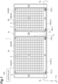
FIG. 1] FIG. 1 is a sectional view of a stocker system according to an embodiment when viewed from the front. - [
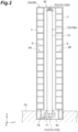
FIG. 2] FIG. 2 is a sectional view of an article storage area of a stocker illustrated inFIG. 1 when viewed from the traveling direction of stacker cranes. - [
FIG. 3] FIG. 3 is a perspective view of a stacker crane included in each stocker inFIG. 1 . - [
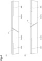
FIG. 4] FIG. 4(A) is an enlarged side view of a connecting portion and its surroundings of an upper traveling rail, andFIG. 4(B) is an enlarged side view of a connecting portion and its surroundings of a lower traveling rail. - [
FIG. 5] FIG. 5(A) to FIG. 5(C) are explanatory diagrams for explaining a configuration to detect the traveling position of the stacker crane. - [
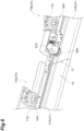
FIG. 6] FIG. 6 is a perspective view of a traveling unit of the stacker crane when viewed from below. - [
FIG. 7] FIG. 7 is a perspective view of an auxiliary traveling unit of the stacker crane when viewed from above. - [
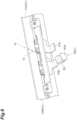
FIG. 8] FIG. 8 is a perspective view illustrating a first lower dog and a second lower dog that are fixed to the lower traveling rail. - [
FIG. 9] FIG. 9 is a perspective view illustrating a first upper dog and a second upper dog that are fixed to the upper traveling rail. - An embodiment will now be described in detail with reference to the drawings. Herein, like or equivalent elements are designated by like reference signs, and duplicate description is omitted.
- As illustrated in
FIG. 1 , a stocker system 1 includes: two stockers of a stocker (first stocker) 2A and a stocker (second stocker) 2B; and a travelingvehicle system 10 according to the embodiment. - As illustrated in
FIG. 1 andFIG. 2 , articles conveyed by a conveying device, for example, are stored in thestockers stockers stocker body 3 and racks 4A, 4B. - In the stocker system 1, the two
stockers first stacker crane 7A and asecond stacker crane 7B). Thestocker body 3 is formed in a housing shape (e.g., a hollow rectangular shape) surrounding a certain area extending in one direction. The external shape of thestocker body 3 is formed with frames and panels (not illustrated). In thestocker body 3, an under-floor area 3S that is part of the interior area of thestocker body 3 is formed at a lower position than a floor GL outside thestocker body 3. - The
stocker body 3 of thestocker 2A forms an article storage area (first area) 11A accommodating theracks maintenance areas stocker 2A in the traveling direction of thestacker cranes 7. Thestocker body 3 of thestocker 2B forms an article storage area (second area) 11B accommodating theracks maintenance areas stocker 2B in the traveling direction of thestacker cranes 7. The maintenance area (shared area) 12B inFIG. 1 is used as both the rightmost maintenance area of thestocker 2A and the leftmost maintenance area of thestocker 2B. - The
article storage area 11A is an area where thefirst stacker crane 7A can travel and thesecond stacker crane 7B cannot travel. Thearticle storage area 11B is an area where thesecond stacker crane 7B can travel and thefirst stacker crane 7A cannot travel. Themaintenance area 12B is an area, formed between thearticle storage area 11A and thearticle storage area 11B, where both thefirst stacker crane 7A and thesecond stacker crane 7B can travel. - As illustrated in
FIG. 4 to FIG. 7 , the travelingvehicle system 10 includes: a lower traveling rail (traveling rail) 31; an upper traveling rail (traveling rail) 32; the first stacker crane (first traveling vehicle) 7A; the second stacker crane (second traveling vehicle) 7B; a first lower rack (first detectable part) 35A and a first upper rack (first detectable part) 35B; a second lower rack (second detectable part) 36A and a second upper rack (second detectable part) 36B; a first lower encoder (first detector) 85A and a first upper encoder (first detector) 85B; and a second lower encoder (second detector) 87A and a second upper encoder (second detector) 87B. - As illustrated in
FIG. 1 , the lower travelingrail 31 includes afirst rail member 31A and asecond rail member 31B extending horizontally. The lower travelingrail 31 may be installed directly on the ground or installed thereon with a support member interposed therebetween. The upper travelingrail 32 includes afirst rail member 32A and asecond rail member 32B extending horizontally. The upper travelingrail 32 may be installed directly on a ceiling, for example, or installed thereon with a suspending member interposed therebetween. The lower travelingrail 31 and the upper travelingrail 32 are disposed inside thestocker bodies 3, and are vertically opposed to each other. - As illustrated in
FIG. 1 andFIG. 4 , thefirst rail member 31A and thesecond rail member 31B are connected with a gap G therebetween or so as to be in contact with each other. Thefirst rail member 32A and thesecond rail member 32B are connected with a gap G therebetween or so as to be in contact with each other. These connecting portions are provided in themaintenance area 12B. - As illustrated in
FIG. 3 andFIG. 6 , eachstacker crane 7 includes a travelingunit 71, amast 72, alifting platform 75, and anauxiliary traveling unit 90. The travelingunit 71 includes a travelingmotor 78 and a liftingmotor 82. - The traveling
unit 71 travels along the lower travelingrail 31. The travelingunit 71 includes a pair of drivingwheels wheels rail 31 therebetween. The travelingmotor 78 is a driving source of thedriving wheels motor 82 is a driving source of thelifting platform 75. Themast 72 is vertically provided with an upper portion of travelingunit 71. Thelifting platform 75 is equipped with a transfer device (not illustrated) and, using this transfer device, transfers an article to and from a shelf S and also transfers an article to and from a loading-and-unloading port. - The
auxiliary traveling unit 90 travels along the upper travelingrail 32. Theauxiliary traveling unit 90 includes a pair of drivingwheels wheels rail 32 therebetween. - As illustrated in
FIG. 1 , the travelingvehicle system 10 according to the present embodiment includes: the first stacker crane (first traveling vehicle) 7A configured to travel on thefirst rail member 31A and thefirst rail member 32A; the second stacker crane (second traveling vehicle) 7B configured to travel on thesecond rail member 31B and thesecond rail member 32B; athird stacker crane 7C configured to travel on thefirst rail member 31A and thefirst rail member 32A; and afourth stacker crane 7D configured to travel on thesecond rail member 31B and thesecond rail member 32B. - As illustrated in
FIG. 1 andFIG. 2 , twostacker cranes 7 travel inside each of thestockers first stacker crane 7A and thethird stacker crane 7C travel inside thestocker 2A, and thesecond stacker crane 7B and thefourth stacker crane 7D travel inside thestocker 2B. Each of thefirst stacker crane 7A and thethird stacker crane 7C travels along thefirst rail member 31A and thefirst rail member 32A, conveys an article between a shelf S and the loading-and-unloading port, and transfers (loads and unloads) the article to and from the shelf S. Each of thesecond stacker crane 7B and thefourth stacker crane 7D travels along thesecond rail member 31B and thesecond rail member 32B, conveys an article between a shelf S and the loading-and-unloading port, and transfers the article to and from the shelf S. - As illustrated in
FIG. 4(B) , the firstlower rack 35A is provided with thefirst rail member 31A and extends along the extending direction of the lower travelingrail 31. On the firstlower rack 35A, teeth are formed that mesh with a sprocket (gear) (not illustrated) attached to the firstlower encoder 85A (seeFIG. 5(C) ). As illustrated inFIG. 4(A) , the firstupper rack 35B is provided with thefirst rail member 32A and extends along the extending direction of the upper travelingrail 32. On the firstupper rack 35B, teeth are formed that mesh with a sprocket (gear) (not illustrated) attached to the firstupper encoder 85B (seeFIG. 5(C) ). - As illustrated in
FIG. 4(B) , the secondlower rack 36A is provided with thesecond rail member 31B and extends along the extending direction of the lower travelingrail 31. On the secondlower rack 36A, teeth are formed that mesh with a sprocket (gear) 88A attached to the secondlower encoder 87A (seeFIG. 6 ). As illustrated inFIG. 4(A) , the secondupper rack 36B is provided with thesecond rail member 32B and extends along the extending direction of the upper travelingrail 32. On the secondupper rack 36B, teeth are formed that mesh with a sprocket (gear) 88B attached to the secondupper encoder 87B (seeFIG. 7 ). - As illustrated in
FIG. 6 , the firstlower rack 35A and the secondlower rack 36A are disposed so as not to overlap each other in the extending direction of the lower travelingrail 31. The firstlower rack 35A and the secondlower rack 36A are disposed in a line along the extending direction of the lower travelingrail 31. As illustrated inFIG. 7 , the firstupper rack 35B and the secondupper rack 36B are disposed so as not to overlap each other in the extending direction of the upper travelingrail 32. The firstupper rack 35B and the secondupper rack 36B are disposed in a line along the extending direction of the upper travelingrail 32. - As illustrated in
FIG. 5(C) , the firstlower encoder 85A is provided with thefirst stacker crane 7A and detects the firstlower rack 35A. More specifically, the firstlower encoder 85A detects the number of rotations of the sprocket (not illustrated) meshing with the firstlower rack 35A. The firstupper encoder 85B is provided with thefirst stacker crane 7A and detects the firstupper rack 35B. More specifically, the firstupper encoder 85B detects the number of rotations of the sprocket (not illustrated) meshing with the firstupper rack 35B. - As illustrated in
FIG. 6 , the secondlower encoder 87A is provided with thesecond stacker crane 7B and detects the secondlower rack 36A. More specifically, the secondlower encoder 87A detects the number of rotations of thesprocket 88A meshing with the secondlower rack 36A. As illustrated inFIG. 7 , the secondupper encoder 87B is provided with thesecond stacker crane 7B and detects the secondupper rack 36B. More specifically, the secondupper encoder 87B detects the number of rotations of thesprocket 88B meshing with the secondupper rack 36B. - As illustrated in
FIG. 5(C) , in the travelingvehicle system 10 according to the present embodiment, the firstlower rack 35A is disposed at a position detectable by the firstlower encoder 85A, the firstupper rack 35B is disposed at a position detectable by the firstupper encoder 85B, the secondlower rack 36A is disposed at a position undetectable by the firstlower encoder 85A, and the secondupper rack 36B is disposed at a position undetectable by the firstupper encoder 85B when thefirst stacker crane 7A is located in a first position P1 being at ends of thefirst rail member 31A and thefirst rail member 32A closer to the respective connecting portions (ends facing the connecting portions) in themaintenance area 12B. - As illustrated in
FIG. 5(B) , in the travelingvehicle system 10 according to the present embodiment, the secondlower rack 36A is disposed at a position detectable by the secondlower encoder 87A, the secondupper rack 36B is disposed at a position detectable by the secondupper encoder 87B, the firstlower rack 35A is disposed at a position undetectable by the secondlower encoder 87A, and the firstupper rack 35B is disposed at a position undetectable by the secondupper encoder 87B when thesecond stacker crane 7B is located in a second position P2 being at ends of thesecond rail member 31B and thesecond rail member 32B closer to the respective connecting portions (ends facing the connecting portions) in themaintenance area 12B. - As illustrated in
FIG. 1 ,shutters 13 are provided at the boundary between thestocker 2A and themaintenance area 12B and the boundary between thestocker 2B and themaintenance area 12B. One of theshutters 13 can be opened and closed so as to be set in an open state in which thefirst stacker crane 7A can come and go between thearticle storage area 11A and themaintenance area 12B, or in a closed state in which thearticle storage area 11A and themaintenance area 12B are shielded from each other and thefirst stacker crane 7A cannot come and go between thearticle storage area 11A and themaintenance area 12B. Similarly, theother shutter 13 can be opened and closed so as to be set in an open state in which thesecond stacker crane 7B can come and go between thearticle storage area 11B and themaintenance area 12B, or in a closed state in which thearticle storage area 11B and themaintenance area 12B are shielded from each other and thesecond stacker crane 7B cannot come and go between thearticle storage area 11B and themaintenance area 12B. - As illustrated in
FIG. 1 , the stocker system 1 includes a controller (first control unit, second control unit) 10A configured to control the travel of the fourstacker cranes 7, for example, provided inside therespective stockers stacker cranes 7 provided inside thestockers racks - The
controller 10A in the present embodiment determines, based on detection results of the firstlower encoder 85A and the firstupper encoder 85B, whether thefirst stacker crane 7A is located in the first position P1 and to determines, based on detection results of the secondlower encoder 87A and the secondupper encoder 87B, whether thesecond stacker crane 7B is located in the second position P2. - More specifically, the
controller 10A determines that thefirst stacker crane 7A is located in the first position P1, based on the number of rotations of the firstlower encoder 85A and/or the firstupper encoder 85B that is detected when it is located in the first position P1. Thecontroller 10A also determines that thesecond stacker crane 7B is located in the second position P2, based on the number of rotations of the secondlower encoder 87A and/or the secondupper encoder 87B that is detected when it is located in the second position P2. - More specifically, the
controller 10A further controls thefirst stacker crane 7A so as not to enter thestocker 2B beyond the first position P1 and also controls thesecond stacker crane 7B so as not to enter thestocker 2A beyond the second position P2, based on the above-described determinations that they are located in the first position P1 and the second position P2. - The following describes functional effects of the stocker system 1 according to the present embodiment. In the stocker system 1 according to the present embodiment, the lower traveling
rail 31 is formed by thefirst rail member 31A and thesecond rail member 31B, and the upper travelingrail 32 is formed by thefirst rail member 32A and thesecond rail member 32B. This allows the gap G to be formed between thefirst rail member 31A and thesecond rail member 31B and between thefirst rail member 32A and thesecond rail member 32B in a manner adjusted to dimensions of the site when the lower travelingrail 31 and the upper travelingrail 32 are disposed, and thus errors with respect to product dimensions can be absorbed. - In the traveling
vehicle system 10 according to the present embodiment, it is possible to detect whether thefirst stacker crane 7A is located at the ends of thefirst rail member 31A and thefirst rail member 32A and whether thesecond stacker crane 7B is located at the ends of thesecond rail member 31B and thesecond rail member 32B in themaintenance area 12B. Thus, thefirst stacker crane 7A andsecond stacker crane 7B can properly detect their own positions. - In the traveling
vehicle system 10 according to the present embodiment, the firstlower rack 35A and the secondlower rack 36A are disposed and the firstupper rack 35B and the secondupper rack 36B are disposed so as not to overlap each other in the extending direction of the lower travelingrail 31 and the upper travelingrail 32. This can reduce the installation space for the firstlower rack 35A, the secondlower rack 36A, the firstupper rack 35B, and the secondupper rack 36B. - In the traveling
vehicle system 10 according to the present embodiment, the firstlower rack 35A and the secondlower rack 36A are disposed in a line along the extending direction of the lower travelingrail 31, and the firstupper rack 35B and the secondupper rack 36B are disposed in a line along the extending direction of the upper travelingrail 32. In this configuration, a unit including the firstlower rack 35A to be attached to thefirst rail member 31A and a unit including the secondlower rack 36A to be attached to thesecond rail member 31B can be standardized. Furthermore, a unit including the firstupper rack 35B to be attached to thefirst rail member 32A and a unit including the secondupper rack 36B to be attached to thesecond rail member 32B can be standardized. - In the present embodiment, the traveling
vehicle system 10 is applied to the stocker system 1 including thestockers stacker cranes 7. This allows the gap G to be formed between thefirst rail member 31A and thesecond rail member 31B and between thefirst rail member 32A and thesecond rail member 32B in a manner adjusted to the dimensions of the site when the lower travelingrail 31 and the upper travelingrail 32 are disposed, and thus errors with respect to the product dimensions can be absorbed. Furthermore, thefirst stacker crane 7A can be prevented from entering the traveling area (stocker 2B) of thesecond stacker crane 7B from themaintenance area 12B, and thesecond stacker crane 7B can be prevented from entering the traveling area (stocker 2A) of thefirst stacker crane 7A from themaintenance area 12B. - Although an embodiment of the present invention has been described above, the present invention is not limited to the embodiment described above, and various modifications may be made without departing from the gist thereof.
- In the above embodiment, an example has been described in which the first
lower rack 35A and the firstupper rack 35B; the secondlower rack 36A and the secondupper rack 36B; the firstlower encoder 85A and the firstupper encoder 85B; and the secondlower encoder 87A and the secondupper encoder 87B are provided. However, instead of or in addition to this configuration, as illustrated inFIG. 8 andFIG. 9 , a first lower dog (third detectable part) 37A and a first upper dog (third detectable part) 38A; a second lower dog (fourth detectable part) 37B and a second upper dog (fourth detectable part) 38B; a first lower sensor (not illustrated) (third detector) and a first upper sensor (third detector) (not illustrated); and a second lower sensor (fourth detector) 93 and a second upper sensor (fourth detector) 94 are provided in a modification. - As illustrated in
FIG. 8 , the firstlower dog 37A is fixed to thefirst rail member 31A, and the secondlower dog 37B is fixed to thesecond rail member 31B. As illustrated inFIG. 9 , the firstupper dog 38A is fixed to thefirst rail member 32A, and the secondupper dog 38B is fixed to thesecond rail member 32B. The first lower sensor is attached to the travelingunit 71 of thefirst stacker crane 7A with a bracket interposed therebetween, and the secondlower sensor 93 is attached to the travelingunit 71 of thesecond stacker crane 7B with abracket 93A interposed therebetween. The first upper sensor is fixed to the auxiliary travelingunit 90 of thefirst stacker crane 7A, and the secondupper sensor 94 is fixed to the auxiliary travelingunit 90 of thesecond stacker crane 7B. Examples of the first lower sensor configured to detect the firstlower dog 37A, the first upper sensor configured to detect the firstupper dog 38A, the secondlower sensor 93 configured to detect the secondlower dog 37B, and the secondupper sensor 94 configured to detect the secondupper dog 38B include proximity sensors and optical sensors. - In a stocker system 1 according to a modification, the controller (first control unit, second control unit) 10A, based on detection results of the first lower sensor and the first upper sensor, stops the travel of the
first stacker crane 7A and, based on detection results of the secondlower sensor 93 and the secondupper sensor 94, stops the travel of thesecond stacker crane 7B. - In a configuration in which the first
lower dog 37A and the firstupper dog 38A, the secondlower dog 37B and the secondupper dog 38B, the first lower sensor and the first upper sensor, and the secondlower sensor 93 and the secondupper sensor 94 are provided instead of the configuration in the above embodiment, it is possible to detect whether thefirst stacker crane 7A is located at the ends of thefirst rail member 31A and thefirst rail member 32A and whether thesecond stacker crane 7B is located at the ends of thesecond rail member 31B and thesecond rail member 32B in themaintenance area 12B. - Furthermore, in the configuration according to this modification, in the
maintenance area 12B, the travel of thefirst stacker crane 7A can be stopped at the ends of thefirst rail member 31A and thefirst rail member 32A, and the travel of thesecond stacker crane 7B can be stopped at the ends of thesecond rail member 31B and thesecond rail member 32B. Thus, thefirst stacker crane 7A can be prevented from entering the traveling area (stocker 2B) of thesecond stacker crane 7B from themaintenance area 12B, and thesecond stacker crane 7B can be prevented from entering the traveling area (stocker 2A) of thefirst stacker crane 7A from themaintenance area 12B. - In the configuration in which the first
lower dog 37A and the firstupper dog 38A, the secondlower dog 37B and the secondupper dog 38B, the first lower sensor and the first upper sensor, the secondlower sensor 93 and the secondupper sensor 94 are provided in addition to the configuration in the above embodiment, even when the traveling position of thefirst stacker crane 7A or thesecond stacker crane 7B cannot be acquired accurately for some reason, thefirst stacker crane 7A can be prevented from entering the traveling area (stocker 2B) of thesecond stacker crane 7B from themaintenance area 12B and thesecond stacker crane 7B can be prevented from entering the traveling area (stocker 2A) of thefirst stacker crane 7A from themaintenance area 12B. - In the embodiment and the modifications above, an example has been described in which the first
lower rack 35A and the firstupper rack 35B are provided and the secondlower rack 36A and the secondupper rack 36B are provided with both the lower travelingrail 31 and the upper travelingrail 32, respectively. However, the present invention is not limited to this configuration. For example, the firstlower rack 35A and the firstupper rack 35B, or the secondlower rack 36A and the secondupper rack 36B may be provided with one of the lower travelingrail 31 and the upper travelingrail 32. In a configuration in which the firstlower rack 35A and the secondlower rack 36A are provided with the lower travelingrail 31, only the firstlower encoder 85A may be provided with thefirst stacker crane 7A and only the secondlower encoder 87A may be provided with thesecond stacker crane 7B. In a configuration in which the firstupper rack 35B and the secondupper rack 36B are provided with the upper travelingrail 32, only the firstupper encoder 85B may be provided with thefirst stacker crane 7A and only the secondupper encoder 87B may be provided with thesecond stacker crane 7B. - In the embodiment and the modifications above, an example has been described in which the gap G is formed between the
first rail member 31A and thesecond rail member 31B and between thefirst rail member 32A and thesecond rail member 32B. However, these rails may be provided so as to be in contact with each other without providing the gap G. Thefirst rail member 31A may be divided into a plurality of members with gaps formed between the members. Similarly, thefirst rail member 32A, thesecond rail member 31B, and thesecond rail member 32B may be divided into a plurality of members with gaps formed between the members. By this configuration, errors between the dimensions of the site where the traveling rails are installed and the product dimensions can be more flexibly absorbed. - When the
first rail member 31A is divided into a plurality of members, the firstlower rack 35A is attached so as to extend across the members after the members are installed on the site. The same applies to the cases when thefirst rail member 32A, thesecond rail member 31B, and thesecond rail member 32B are divided into a plurality of members, and the firstupper rack 35B, the secondlower rack 36A, and the secondupper rack 36B each are also attached to their respective members in the same manner. - Even when the gaps are formed in each of the
first rail members second rail members first rail member 31A and thesecond rail member 31B and the gap G corresponding to the connecting portion between thefirst rail member 32A and thesecond rail member 32B are formed each at one location. More specifically, each of the ends (the first position P1) of thefirst rail members maintenance area 12B is an end facing the corresponding one gap G described above, and is also an end of a range in which thefirst stacker crane 7A can travel on thefirst rail members second rail members maintenance area 12B is an end facing the corresponding one gap G described above, and is also an end of a range in which thesecond stacker crane 7B can travel on thesecond rail members - In the above modifications, an example has been described in which the second
lower sensor 93 and the secondupper sensor 94 that are detectors are provided with thefirst stacker crane 7A and thesecond stacker crane 7B, and the firstlower dog 37A, the secondlower dog 37B, the firstupper dog 38A, and the secondupper dog 38B that are detectable parts are provided with the lower travelingrail 31 and the upper travelingrail 32. However, the detectable parts may be provided with thefirst stacker crane 7A and thesecond stacker crane 7B, and the detectors may be provided with the lower travelingrail 31 and the upper travelingrail 32. -
- 1
- stocker system
- 2A
- stocker (first stocker)
- 2B
- stocker (first stocker)
- 7A
- first stacker crane
- 7B
- second stacker crane
- 10
- traveling vehicle system
- 10A
- controller (first control unit, second control unit)
- 11A
- article storage area (first area)
- 11B
- article storage area (second area)
- 12B
- maintenance area (shared area)
- 31
- lower traveling rail (traveling rail)
- 31A, 32A
- first rail member
- 31B, 32B
- second rail member
- 32
- upper traveling rail (traveling rail)
- 35A
- first lower rack (first detectable part)
- 35B
- first upper rack (first detectable part)
- 36A
- second lower rack (second detectable part)
- 36B
- second upper rack (second detectable part)
- 37A
- first lower dog (third detectable part)
- 37B
- second lower dog (fourth detectable part)
- 38A
- first upper dog (third detectable part)
- 38B
- second upper dog (fourth detectable part)
- 85A
- first lower encoder (first detector)
- 85B
- first upper encoder (first detector)
- 87A
- second lower encoder (second detector)
- 87B
- second upper encoder (second detector)
- 93
- second lower sensor (fourth detector)
- 94
- second upper sensor (fourth detector)
- G
- gap
- P1
- first position
- P2
- second position
Claims (11)
- A traveling vehicle system comprising:a traveling rail including a first rail member and a second rail member extending horizontally;a first traveling vehicle and a second traveling vehicle configured to travel on the traveling rail;a first detectable part provided with the first rail member and extending along an extending direction of the traveling rail;a second detectable part provided with the second rail member and extending along the extending direction of the traveling rail;a first detector provided with the first traveling vehicle and configured to detect the first detectable part; anda second detector provided with the second traveling vehicle and configured to detect the second detectable part, whereinalong the traveling rail, a first area where the first traveling vehicle is able to travel and the second traveling vehicle is unable to travel; a second area where the second traveling vehicle is able to travel and the first traveling vehicle is unable to travel; and a shared area, provided between the first area and the second area, where both the first traveling vehicle and the second traveling vehicle are able to travel are formed,the shared area is provided with a connecting portion in which the first rail member and the second rail member are connected with a gap therebetween or so as to be in contact with each other,the first detectable part is disposed at a position detectable by the first detector and the second detectable part is disposed at a position undetectable by the first detector when the first traveling vehicle is located in a first position being at an end of the first rail member closer to the connecting portion in the shared area, andthe second detectable part is disposed at a position detectable by the second detector and the first detectable part is disposed at a position undetectable by the second detector when the second traveling vehicle is located in a second position being at an end of the second rail member closer to the connecting portion in the shared area.
- The traveling vehicle system according to claim 1, wherein the first detectable part and the second detectable part are disposed so as not to overlap each other in the extending direction of the traveling rail.
- The traveling vehicle system according to claim 1 or 2, wherein the first detectable part and the second detectable part are disposed in a line along the extending direction of the traveling rail.
- The traveling vehicle system according to any one of claims 1 to 3, wherein
the first detector and the second detector are encoders, and the first detectable part and the second detectable part are racks configured to mesh with gears attached to the encoders. - The traveling vehicle system according to any one of claims 1 to 4, further comprising a first control unit configured to determine whether the first traveling vehicle is located in the first position based on a detection result of the first detector and to determine whether the second traveling vehicle is located in the second position based on a detection result of the second detector, wherein
the first control unit controls the first traveling vehicle so as not to enter the second area beyond the first position and controls the second traveling vehicle so as not to enter the connecting portion beyond the second position. - The traveling vehicle system according to any one of claims 1 to 5, further comprising:a third detector configured to detect a third detectable part; anda fourth detector configured to detect a fourth detectable part, whereinone of the third detector and the third detectable part is provided with one of the first traveling vehicle and the shared area and the other of the third detector and the third detectable part is provided with the other of the first traveling vehicle and the shared area,one of the fourth detector and the fourth detectable part is provided with one of the second traveling vehicle and the shared area and the other of the fourth detector and the fourth detectable part is provided with the other of the second traveling vehicle and the shared area,the third detectable part is disposed at a position detectable by the third detector and the fourth detectable part is disposed at a position undetectable by the third detector when the first traveling vehicle is located in the first position being at the end of the first rail member closer to the connecting portion in the shared area, andthe fourth detectable part is disposed at a position detectable by the fourth detector and the third detectable part is disposed at a position undetectable by the fourth detector when the first traveling vehicle is located in the second position being at the end of the second rail member closer to the connecting portion in the shared area.
- A traveling vehicle system comprising:a traveling rail including a first rail member and a second rail member extending horizontally;a first traveling vehicle and a second traveling vehicle configured to travel on the traveling rail;a third detector configured to detect a third detectable part; anda fourth detector configured to detect a fourth detectable part, whereinalong the traveling rail, a first area where the first traveling vehicle is able to travel and the second traveling vehicle is unable to travel, a second area where the second traveling vehicle is able to travel and the first traveling vehicle is unable to travel, and a shared area provided between the first area and the second area where both the first traveling vehicle and the second traveling vehicle are able to travel are formed,the shared area is provided with a connecting portion in which the first rail member and the second rail member are connected with a gap therebetween or so as to be in contact with each other,one of the third detector and the third detectable part is provided with one of the first traveling vehicle and the shared area and the other of the third detector and the third detectable part is provided with the other of the first traveling vehicle and the shared area,one of the fourth detector and the fourth detectable part is provided with one of the second traveling vehicle and the shared area, and the other of the fourth detector and the fourth detectable part is provided with the other of the second traveling vehicle and the shared area,the third detectable part is disposed at a position detectable by the third detector and the fourth detectable part is disposed at a position undetectable by the third detector when the first traveling vehicle is located in a first position being at an end of the first rail member closer to the connecting portion in the shared area, andthe fourth detectable part is disposed at a position detectable by the fourth detector and the third detectable part is disposed at a position undetectable by the fourth detector when the first traveling vehicle is located in a second position being at an end of the second rail member closer to the connecting portion in the shared area.
- The traveling vehicle system according to claim 7, whereinthe third detector is provided with the first traveling vehicle and the third detectable part is provided in the shared area, andthe fourth detector is provided with the second traveling vehicle and the fourth detectable part is provided in the shared area.
- The traveling vehicle system according to any one of claims 6 to 8, whereinthe third detector and the fourth detector are sensors, andthe third detectable part and the fourth detectable part are dogs configured to be detected by the sensors.
- The traveling vehicle system according to any one of claims 6 to 9, further comprising a second control unit configured to stop travel of the first traveling vehicle based on a detection result of the third detector and to stop travel of the second traveling vehicle based on a detection result of the fourth detector.
- A stocker system comprising:the traveling vehicle system according to any one of claims 1 to 10;a first stocker provided such that an article is able to be loaded and unloaded between the first stocker and the first traveling vehicle traveling in the first area;a second stocker provided such that an article is able to be loaded and unloaded between the second stocker and the second traveling vehicle traveling in the second area; anda maintenance area disposed between the first stocker and the second stocker along the extending direction of the traveling rail and capable of accommodating the first traveling vehicle and the second traveling vehicles located in the shared area.
Applications Claiming Priority (2)
| Application Number | Priority Date | Filing Date | Title |
|---|---|---|---|
| JP2020056010 | 2020-03-26 | ||
| PCT/JP2021/004822 WO2021192675A1 (en) | 2020-03-26 | 2021-02-09 | Traveling vehicle system |
Publications (3)
| Publication Number | Publication Date |
|---|---|
| EP4130918A1 true EP4130918A1 (en) | 2023-02-08 |
| EP4130918A4 EP4130918A4 (en) | 2024-08-14 |
| EP4130918B1 EP4130918B1 (en) | 2025-08-06 |
Family
ID=77891372
Family Applications (1)
| Application Number | Title | Priority Date | Filing Date |
|---|---|---|---|
| EP21775864.8A Active EP4130918B1 (en) | 2020-03-26 | 2021-02-09 | Traveling vehicle system |
Country Status (8)
| Country | Link |
|---|---|
| US (1) | US12421030B2 (en) |
| EP (1) | EP4130918B1 (en) |
| JP (1) | JP7367851B2 (en) |
| KR (1) | KR102768812B1 (en) |
| CN (1) | CN115349113B (en) |
| IL (1) | IL296655B2 (en) |
| TW (1) | TWI834958B (en) |
| WO (1) | WO2021192675A1 (en) |
Families Citing this family (2)
| Publication number | Priority date | Publication date | Assignee | Title |
|---|---|---|---|---|
| JP7201076B2 (en) * | 2019-05-14 | 2023-01-10 | 村田機械株式会社 | Stocker system |
| IL301798B2 (en) * | 2020-10-06 | 2025-11-01 | Murata Machinery Ltd | Goods sorter |
Family Cites Families (21)
| Publication number | Priority date | Publication date | Assignee | Title |
|---|---|---|---|---|
| JPH08192904A (en) * | 1995-01-13 | 1996-07-30 | Toyota Autom Loom Works Ltd | Method of stopping crane device, and stopping device, and corrctive data making device |
| JP4089154B2 (en) * | 2000-12-07 | 2008-05-28 | 株式会社ダイフク | Travel control method for moving body |
| FI20031259L (en) * | 2003-09-04 | 2005-03-05 | Fastems Oy Ab | Multi-rack elevator system and method for controlling the same |
| EP1728738B1 (en) * | 2005-05-31 | 2008-09-17 | Daifuku Co., Ltd. | Article transport facility and a method of operating the facility |
| JP2007323112A (en) | 2006-05-30 | 2007-12-13 | Ishikawajima Transport Machinery Co Ltd | Collision prevention control device and method for transfer device |
| JP4775650B2 (en) | 2006-09-05 | 2011-09-21 | 株式会社ダイフク | Mobile equipment |
| JP4756371B2 (en) * | 2006-09-05 | 2011-08-24 | 株式会社ダイフク | Goods storage equipment |
| JP2010247931A (en) * | 2009-04-14 | 2010-11-04 | Toyota Industries Corp | Automatic warehouse system |
| WO2011070869A1 (en) * | 2009-12-07 | 2011-06-16 | 国立大学法人東京大学 | Mobile body system |
| JP5527283B2 (en) * | 2011-05-23 | 2014-06-18 | 村田機械株式会社 | Traveling vehicle system |
| JP5810928B2 (en) * | 2012-01-11 | 2015-11-11 | 村田機械株式会社 | Tracked vehicle system |
| JP2013166620A (en) * | 2012-02-15 | 2013-08-29 | Murata Machinery Ltd | Stacker crane |
| WO2014038370A1 (en) * | 2012-09-06 | 2014-03-13 | 村田機械株式会社 | Transfer device |
| EP3015401B1 (en) * | 2013-06-28 | 2018-07-04 | Murata Machinery, Ltd. | Automated warehouse and operation method for same |
| CN106660702B (en) * | 2014-08-25 | 2019-03-08 | 村田机械株式会社 | Automatic warehouse and control method of automatic warehouse |
| JP6201977B2 (en) * | 2014-12-19 | 2017-09-27 | 村田機械株式会社 | Automatic warehouse and its operation method |
| JP6693481B2 (en) * | 2017-06-26 | 2020-05-13 | 株式会社ダイフク | Article transport equipment and article transport vehicle |
| US11999563B2 (en) * | 2018-08-06 | 2024-06-04 | Murata Machinery, Ltd. | Automated warehouse and conveyance device |
| JP7201076B2 (en) * | 2019-05-14 | 2023-01-10 | 村田機械株式会社 | Stocker system |
| IL301798B2 (en) * | 2020-10-06 | 2025-11-01 | Murata Machinery Ltd | Goods sorter |
| JP7314916B2 (en) * | 2020-11-04 | 2023-07-26 | 株式会社ダイフク | Goods transport equipment |
-
2021
- 2021-02-09 JP JP2022509372A patent/JP7367851B2/en active Active
- 2021-02-09 CN CN202180024215.5A patent/CN115349113B/en active Active
- 2021-02-09 IL IL296655A patent/IL296655B2/en unknown
- 2021-02-09 US US17/906,907 patent/US12421030B2/en active Active
- 2021-02-09 WO PCT/JP2021/004822 patent/WO2021192675A1/en not_active Ceased
- 2021-02-09 KR KR1020227021462A patent/KR102768812B1/en active Active
- 2021-02-09 EP EP21775864.8A patent/EP4130918B1/en active Active
- 2021-03-19 TW TW110109906A patent/TWI834958B/en active
Also Published As
| Publication number | Publication date |
|---|---|
| IL296655B2 (en) | 2025-08-01 |
| CN115349113A (en) | 2022-11-15 |
| KR102768812B1 (en) | 2025-02-18 |
| JPWO2021192675A1 (en) | 2021-09-30 |
| KR20220104039A (en) | 2022-07-25 |
| WO2021192675A1 (en) | 2021-09-30 |
| EP4130918B1 (en) | 2025-08-06 |
| US20230294916A1 (en) | 2023-09-21 |
| EP4130918A4 (en) | 2024-08-14 |
| JP7367851B2 (en) | 2023-10-24 |
| IL296655B1 (en) | 2025-04-01 |
| TWI834958B (en) | 2024-03-11 |
| TW202140354A (en) | 2021-11-01 |
| IL296655A (en) | 2022-11-01 |
| CN115349113B (en) | 2025-09-23 |
| US12421030B2 (en) | 2025-09-23 |
Similar Documents
| Publication | Publication Date | Title |
|---|---|---|
| EP4130918B1 (en) | Traveling vehicle system | |
| KR102659882B1 (en) | Ceiling carrier and ceiling carrier system | |
| US6791074B2 (en) | Light curtain system for establishing a protective light curtain, tool and system for processing objects and method for loading/unloading a tool | |
| WO2022135140A1 (en) | Cargo loading and unloading control method and apparatus, cargo loading and unloading apparatus, and warehousing system | |
| JP7283640B2 (en) | Stocker | |
| CN106660702A (en) | Automated warehouse and automated warehouse control method | |
| JP5983855B2 (en) | Transport system | |
| KR20230095152A (en) | Cross Rail Structure for OHT System and OHT System using thereof | |
| KR101564543B1 (en) | Safety guide system and wafer box horizontal and vertical transfer system with the same | |
| JP4465415B2 (en) | Ceiling traveling transfer device | |
| KR101539316B1 (en) | Overhead hoist trasporter controll sensor system | |
| JP4358085B2 (en) | Mechanical parking device safety device | |
| JP4314521B2 (en) | Article conveying device | |
| US20250296773A1 (en) | Stacker | |
| JP2006290177A (en) | Overhead traveling vehicle system | |
| US20230138966A1 (en) | Automated Warehouse | |
| KR100636601B1 (en) | Transfer robot driving at a ceiling | |
| JP2011032069A (en) | Carrying device | |
| KR100690019B1 (en) | Unmanned Cargo Transport System using Monorail | |
| KR101893980B1 (en) | Inter-layer transfer system | |
| JP2663045B2 (en) | Self-failure detection method of detection device in mechanical parking device | |
| JPH11314890A (en) | Elevating mechanism and carrier transport device | |
| JP3957426B2 (en) | Stop position detection device for mechanical parking equipment | |
| JP2006298565A (en) | Overhead traveling vehicle system | |
| KR20060131407A (en) | Stocker system and its driving method |
Legal Events
| Date | Code | Title | Description |
|---|---|---|---|
| STAA | Information on the status of an ep patent application or granted ep patent |
Free format text: STATUS: THE INTERNATIONAL PUBLICATION HAS BEEN MADE |
|
| PUAI | Public reference made under article 153(3) epc to a published international application that has entered the european phase |
Free format text: ORIGINAL CODE: 0009012 |
|
| STAA | Information on the status of an ep patent application or granted ep patent |
Free format text: STATUS: REQUEST FOR EXAMINATION WAS MADE |
|
| 17P | Request for examination filed |
Effective date: 20221013 |
|
| AK | Designated contracting states |
Kind code of ref document: A1 Designated state(s): AL AT BE BG CH CY CZ DE DK EE ES FI FR GB GR HR HU IE IS IT LI LT LU LV MC MK MT NL NO PL PT RO RS SE SI SK SM TR |
|
| DAV | Request for validation of the european patent (deleted) | ||
| DAX | Request for extension of the european patent (deleted) | ||
| REG | Reference to a national code |
Ref legal event code: R079 Ipc: B65G0001040000 Ref country code: DE Ref legal event code: R079 Ref document number: 602021035697 Country of ref document: DE Free format text: PREVIOUS MAIN CLASS: G05D0001020000 Ipc: B65G0001040000 |
|
| A4 | Supplementary search report drawn up and despatched |
Effective date: 20240712 |
|
| RIC1 | Information provided on ipc code assigned before grant |
Ipc: B66F 9/07 20060101ALI20240708BHEP Ipc: B65G 1/04 20060101AFI20240708BHEP |
|
| GRAP | Despatch of communication of intention to grant a patent |
Free format text: ORIGINAL CODE: EPIDOSNIGR1 |
|
| STAA | Information on the status of an ep patent application or granted ep patent |
Free format text: STATUS: GRANT OF PATENT IS INTENDED |
|
| INTG | Intention to grant announced |
Effective date: 20250407 |
|
| GRAS | Grant fee paid |
Free format text: ORIGINAL CODE: EPIDOSNIGR3 |
|
| GRAA | (expected) grant |
Free format text: ORIGINAL CODE: 0009210 |
|
| STAA | Information on the status of an ep patent application or granted ep patent |
Free format text: STATUS: THE PATENT HAS BEEN GRANTED |
|
| AK | Designated contracting states |
Kind code of ref document: B1 Designated state(s): AL AT BE BG CH CY CZ DE DK EE ES FI FR GB GR HR HU IE IS IT LI LT LU LV MC MK MT NL NO PL PT RO RS SE SI SK SM TR |
|
| REG | Reference to a national code |
Ref country code: GB Ref legal event code: FG4D |
|
| REG | Reference to a national code |
Ref country code: CH Ref legal event code: EP |
|
| REG | Reference to a national code |
Ref country code: IE Ref legal event code: FG4D |
|
| REG | Reference to a national code |
Ref country code: DE Ref legal event code: R096 Ref document number: 602021035697 Country of ref document: DE |
|
| REG | Reference to a national code |
Ref country code: NL Ref legal event code: MP Effective date: 20250806 |
|
| PG25 | Lapsed in a contracting state [announced via postgrant information from national office to epo] |
Ref country code: IS Free format text: LAPSE BECAUSE OF FAILURE TO SUBMIT A TRANSLATION OF THE DESCRIPTION OR TO PAY THE FEE WITHIN THE PRESCRIBED TIME-LIMIT Effective date: 20251206 |
|
| PG25 | Lapsed in a contracting state [announced via postgrant information from national office to epo] |
Ref country code: NO Free format text: LAPSE BECAUSE OF FAILURE TO SUBMIT A TRANSLATION OF THE DESCRIPTION OR TO PAY THE FEE WITHIN THE PRESCRIBED TIME-LIMIT Effective date: 20251106 |
|
| REG | Reference to a national code |
Ref country code: LT Ref legal event code: MG9D |
|
| PG25 | Lapsed in a contracting state [announced via postgrant information from national office to epo] |
Ref country code: PT Free format text: LAPSE BECAUSE OF FAILURE TO SUBMIT A TRANSLATION OF THE DESCRIPTION OR TO PAY THE FEE WITHIN THE PRESCRIBED TIME-LIMIT Effective date: 20251209 |
|
| PG25 | Lapsed in a contracting state [announced via postgrant information from national office to epo] |
Ref country code: FI Free format text: LAPSE BECAUSE OF FAILURE TO SUBMIT A TRANSLATION OF THE DESCRIPTION OR TO PAY THE FEE WITHIN THE PRESCRIBED TIME-LIMIT Effective date: 20250806 |
|
| PG25 | Lapsed in a contracting state [announced via postgrant information from national office to epo] |
Ref country code: HR Free format text: LAPSE BECAUSE OF FAILURE TO SUBMIT A TRANSLATION OF THE DESCRIPTION OR TO PAY THE FEE WITHIN THE PRESCRIBED TIME-LIMIT Effective date: 20250806 Ref country code: NL Free format text: LAPSE BECAUSE OF FAILURE TO SUBMIT A TRANSLATION OF THE DESCRIPTION OR TO PAY THE FEE WITHIN THE PRESCRIBED TIME-LIMIT Effective date: 20250806 |
|
| PG25 | Lapsed in a contracting state [announced via postgrant information from national office to epo] |
Ref country code: GR Free format text: LAPSE BECAUSE OF FAILURE TO SUBMIT A TRANSLATION OF THE DESCRIPTION OR TO PAY THE FEE WITHIN THE PRESCRIBED TIME-LIMIT Effective date: 20251107 |
|
| PG25 | Lapsed in a contracting state [announced via postgrant information from national office to epo] |
Ref country code: SE Free format text: LAPSE BECAUSE OF FAILURE TO SUBMIT A TRANSLATION OF THE DESCRIPTION OR TO PAY THE FEE WITHIN THE PRESCRIBED TIME-LIMIT Effective date: 20250806 |
|
| PG25 | Lapsed in a contracting state [announced via postgrant information from national office to epo] |
Ref country code: LV Free format text: LAPSE BECAUSE OF FAILURE TO SUBMIT A TRANSLATION OF THE DESCRIPTION OR TO PAY THE FEE WITHIN THE PRESCRIBED TIME-LIMIT Effective date: 20250806 |
|
| PG25 | Lapsed in a contracting state [announced via postgrant information from national office to epo] |
Ref country code: BG Free format text: LAPSE BECAUSE OF FAILURE TO SUBMIT A TRANSLATION OF THE DESCRIPTION OR TO PAY THE FEE WITHIN THE PRESCRIBED TIME-LIMIT Effective date: 20250806 Ref country code: PL Free format text: LAPSE BECAUSE OF FAILURE TO SUBMIT A TRANSLATION OF THE DESCRIPTION OR TO PAY THE FEE WITHIN THE PRESCRIBED TIME-LIMIT Effective date: 20250806 |
|
| PG25 | Lapsed in a contracting state [announced via postgrant information from national office to epo] |
Ref country code: RS Free format text: LAPSE BECAUSE OF FAILURE TO SUBMIT A TRANSLATION OF THE DESCRIPTION OR TO PAY THE FEE WITHIN THE PRESCRIBED TIME-LIMIT Effective date: 20251106 |
|
| PG25 | Lapsed in a contracting state [announced via postgrant information from national office to epo] |
Ref country code: ES Free format text: LAPSE BECAUSE OF FAILURE TO SUBMIT A TRANSLATION OF THE DESCRIPTION OR TO PAY THE FEE WITHIN THE PRESCRIBED TIME-LIMIT Effective date: 20250806 |
|
| REG | Reference to a national code |
Ref country code: AT Ref legal event code: MK05 Ref document number: 1821630 Country of ref document: AT Kind code of ref document: T Effective date: 20250806 |
|
| PG25 | Lapsed in a contracting state [announced via postgrant information from national office to epo] |
Ref country code: SM Free format text: LAPSE BECAUSE OF FAILURE TO SUBMIT A TRANSLATION OF THE DESCRIPTION OR TO PAY THE FEE WITHIN THE PRESCRIBED TIME-LIMIT Effective date: 20250806 |
|
| PG25 | Lapsed in a contracting state [announced via postgrant information from national office to epo] |
Ref country code: DK Free format text: LAPSE BECAUSE OF FAILURE TO SUBMIT A TRANSLATION OF THE DESCRIPTION OR TO PAY THE FEE WITHIN THE PRESCRIBED TIME-LIMIT Effective date: 20250806 |
|
| PGFP | Annual fee paid to national office [announced via postgrant information from national office to epo] |
Ref country code: DE Payment date: 20260121 Year of fee payment: 6 |
|
| PG25 | Lapsed in a contracting state [announced via postgrant information from national office to epo] |
Ref country code: AT Free format text: LAPSE BECAUSE OF FAILURE TO SUBMIT A TRANSLATION OF THE DESCRIPTION OR TO PAY THE FEE WITHIN THE PRESCRIBED TIME-LIMIT Effective date: 20250806 |
|
| PG25 | Lapsed in a contracting state [announced via postgrant information from national office to epo] |
Ref country code: IT Free format text: LAPSE BECAUSE OF FAILURE TO SUBMIT A TRANSLATION OF THE DESCRIPTION OR TO PAY THE FEE WITHIN THE PRESCRIBED TIME-LIMIT Effective date: 20250806 |
|
| PG25 | Lapsed in a contracting state [announced via postgrant information from national office to epo] |
Ref country code: CZ Free format text: LAPSE BECAUSE OF FAILURE TO SUBMIT A TRANSLATION OF THE DESCRIPTION OR TO PAY THE FEE WITHIN THE PRESCRIBED TIME-LIMIT Effective date: 20250806 |
|
| PG25 | Lapsed in a contracting state [announced via postgrant information from national office to epo] |
Ref country code: EE Free format text: LAPSE BECAUSE OF FAILURE TO SUBMIT A TRANSLATION OF THE DESCRIPTION OR TO PAY THE FEE WITHIN THE PRESCRIBED TIME-LIMIT Effective date: 20250806 Ref country code: SK Free format text: LAPSE BECAUSE OF FAILURE TO SUBMIT A TRANSLATION OF THE DESCRIPTION OR TO PAY THE FEE WITHIN THE PRESCRIBED TIME-LIMIT Effective date: 20250806 |