JP4465415B2 - Ceiling traveling transfer device - Google Patents
Ceiling traveling transfer device Download PDFInfo
- Publication number
- JP4465415B2 JP4465415B2 JP2000073163A JP2000073163A JP4465415B2 JP 4465415 B2 JP4465415 B2 JP 4465415B2 JP 2000073163 A JP2000073163 A JP 2000073163A JP 2000073163 A JP2000073163 A JP 2000073163A JP 4465415 B2 JP4465415 B2 JP 4465415B2
- Authority
- JP
- Japan
- Prior art keywords
- obstacle detection
- obstacle
- overhead traveling
- path
- load port
- Prior art date
- Legal status (The legal status is an assumption and is not a legal conclusion. Google has not performed a legal analysis and makes no representation as to the accuracy of the status listed.)
- Expired - Fee Related
Links
- 238000012546 transfer Methods 0.000 title description 16
- 238000001514 detection method Methods 0.000 claims abstract description 110
- 238000004519 manufacturing process Methods 0.000 claims abstract description 56
- 238000012544 monitoring process Methods 0.000 claims description 45
- 230000003287 optical effect Effects 0.000 claims description 8
- 230000001174 ascending effect Effects 0.000 claims description 5
- 239000004065 semiconductor Substances 0.000 abstract description 47
- 230000003028 elevating effect Effects 0.000 abstract description 6
- 230000032258 transport Effects 0.000 description 31
- 235000012431 wafers Nutrition 0.000 description 30
- 239000000725 suspension Substances 0.000 description 8
- 230000000694 effects Effects 0.000 description 6
- 238000000034 method Methods 0.000 description 4
- 230000006870 function Effects 0.000 description 3
- 238000012545 processing Methods 0.000 description 3
- 238000009434 installation Methods 0.000 description 2
- 238000012423 maintenance Methods 0.000 description 2
- 230000007257 malfunction Effects 0.000 description 2
- WWYNJERNGUHSAO-XUDSTZEESA-N (+)-Norgestrel Chemical compound O=C1CC[C@@H]2[C@H]3CC[C@](CC)([C@](CC4)(O)C#C)[C@@H]4[C@@H]3CCC2=C1 WWYNJERNGUHSAO-XUDSTZEESA-N 0.000 description 1
- 230000005856 abnormality Effects 0.000 description 1
- 230000001678 irradiating effect Effects 0.000 description 1
- 239000000463 material Substances 0.000 description 1
- 230000002093 peripheral effect Effects 0.000 description 1
- 230000002265 prevention Effects 0.000 description 1
- 229910052710 silicon Inorganic materials 0.000 description 1
- 239000010703 silicon Substances 0.000 description 1
- 238000004381 surface treatment Methods 0.000 description 1
Images


Landscapes
- Warehouses Or Storage Devices (AREA)
- Carriers, Traveling Bodies, And Overhead Traveling Cranes (AREA)
- Control And Safety Of Cranes (AREA)
- Container, Conveyance, Adherence, Positioning, Of Wafer (AREA)
Abstract
Description
【0001】
【発明の属する技術分野】
本発明は、天井に配設された軌道を走行し、搬送物を吊り下げ状態でクリーンルーム内等に配置された各半導体製造装置間で搬送する天井走行搬送装置に関するものである。
【0002】
【従来の技術】
半導体デバイスの製造を行う製造設備にあっては、種々装置間において半導体ウェーハの搬送を自動的に行う搬送装置が用いられているが、この種の搬送装置の一つとして軌道式の搬送装置がある。一般的な軌道式の搬送装置は、天井または床面に設置された軌道にて搬送台車を走行させるよう構成されており、通常、軌道の側方に各種半導体ウェーハの加工を行う製造装置を備えている。
一般に半導体デバイスは、シリコンなどの半導体ウエーハが、様々な半導体製造装置(ウエーハ処理装置、保管装置、作業台、バッファ装置等)の間を往来して何百工程という工程処理を経て製造される。
【0003】
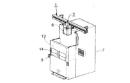
軌道を天井に配した天井走行搬送装置の一例について、図17を参照しながら、以下に説明する。例えば、クリーンルームにおける半導体製造装置用の天井走行搬送装置においては、天井側の軌道1を走行するホイスト付台車3を用い、半導体ウェーハ2の入ったウェーハキャリア6を半導体製造装置7同志の間または半導体製造装置7とストッカ7Aとの間で搬送しながら処理することが行われている。
同図に示すホイスト付台車3は、軌道1に沿って走行する走行部3a、この走行部3aに設けられたハンド吊り下げ部4により昇降自在に吊り下げられたハンド5からなり、半導体製造装置7のロードポート8に置かれたウェーハキャリア6をハンド5で把持し、ハンド吊り下げ部4がハンド5を上昇させた後、走行部3aにより軌道1に沿って走行する構造となっている。
ところで、前記クリーンルーム内には、同図に示すように、前記天井側に設けられた軌道1に沿って複数の半導体製造装置7が並設されており、複数のホイスト付台車3により各半導体製造装置7のロードポート8上からウェーハキャリア6を把持して、他の半導体製造装置7に搬送するようになっている。
【0004】
上記説明の天井走行搬送装置による半導体ウェーハ2の搬送は、以下のように行われる。まず、軌道1に沿ってホイスト付台車3を走行させ、これから搬送を行うウェーハキャリア6のあるロードポート8の上方にて停止させる。そして、ハンド吊り下げ部4を巻下げてハンド5を下降させ、該ハンド5によってウェーハキャリア6を保持する。そして、ハンド吊り下げ部4を巻き上げてウェーハキャリア6をロードポート8から取り上げ、最上位高さに巻き上げた後、再びホイスト付台車3は走行を開始する。
そして、次工程を行う他の半導体製造装置7やストッカ7Aのロードポート8などの上方にて停止する。ハンド吊り下げ部4を巻下げてハンド5を下降させ、このロードポート8上にウェーハキャリア6が完全に載置された後、ハンド5はウェーハキャリア6を放してハンド吊り下げ部4の巻き上げとともに上昇し、次の搬送作業へと移る。
【0005】
ところで、天井走行搬送装置は、ウェーハキャリア6等の搬送物をロードポート8上で上げ下げする関係上、搬送物の落下や、搬送物の吊り下げ時における、人や不用意に置かれた物などの障害物(図示せず)との接触などの不具合を避けるために、様々な対策が検討されている。
【0006】
この従来の対策案の例について、図18から図21を参照しながら、以下に説明する。
これら対策案は、J300(Japan 300mm Semiconductor Technology Confer-ence)とI300I(International 300mm Initiative)とのジョイントガイダンスで発表されたものである。なお、図17に説明したものと同一構成要素には、同一符号を付し、その説明を省略する。
【0007】
図18は、非常停止スイッチ9を半導体製造装置7の近傍(例えば、この図では、ロードポート8の上面)に設け、不具合が発生する前、または発生後に図示されない運転者がこれを押すことで、ハンド5やウェーハキャリア6の昇降動作を停止させるものである。なお、説明のために、以降この案を対策案Aと呼ぶ。
図19は、ロードポート8の手前側に、光センサによる光のカーテン10を巡らせ、人などの障害物がこの光のカーテン10を遮った場合に、半導体製造装置7が異常を検知してウェーハキャリア6の昇降動作を停止させるものである。なお、説明のために、以降この案を対策案Bと呼ぶ。
【0008】
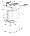
図20は、ロードポート8の上部に壁部11と手動扉12とを設けて、ロードポート8の上方の空間を覆ったものである。メンテナンスなどのためにロードポート8内にアクセスする必要がある場合には、手動扉12を手動で開いて行うが、この手動扉12には、その開状態を感知するセンサー13が設けられており、手動扉12が開かれた状態では、センサー13が感知してウェーハキャリア6の昇降動作を停止させるものである。なお、説明のために、以降この案を対策案Cと呼ぶ。
図21は、対策案Cにおける手動扉12の代わりに、自動的に開閉する自動扉14を設けたものである。この案においても、対策案Cと同様にセンサー13が設けられている。なお、説明のために、以降、この案を対策案Dと呼ぶ。
【0009】
【発明が解決しようとする課題】
ところで、上記説明の従来の対策案A、B、C、Dは、以下のような問題を有しているため、現実的なものではなかった。
すなわち、対策案Aは、多数有る各半導体製造装置7の全てを前記運転者が監視していなければならず、この運転者の咄嗟の判断を必要とすることから、常時適切に対応できるものではなかった。
また、対策案B、C、Dは、多数(一般的には、300台〜400台。ちなみに、この場合のホイスト付台車3は、数十台程度)有る半導体製造装置7の各ロードポート8(一般的には、1台あたり2〜4個)全てに対応するには、1000箇所以上に対策を講じる必要があり、半導体製造装置7の製造コストや保守費用が高くなるという問題を起こすことになる。
【0010】
本発明は、上記事情を鑑みてなされたものであって、下記をその目的としている。すなわち、吊り下げ時の搬送物が、人や不用意に置かれた物などの障害物と接触する前にこれを検知してこれを避ける対策を、安価かつ確実に講じることができる天井走行搬送装置の提供を目的とする。
【0011】
【課題を解決するための手段】
本発明の天井走行搬送装置は、上記課題を解決するために以下の手段を採用した。すなわち、請求項1記載の天井走行搬送装置は、天井に設置された軌道と、該軌道に沿って走行するホイスト付台車とを備えた天井走行搬送装置において、前記ホイスト付台車は、その複数の側壁のそれぞれに、当台車と各製造装置のロードポート間との昇降経路を光探索し障害物の有無を検知する障害物検知センサを備え、前記障害物検知センサは、前記側壁に直交する方向から見て当該障害物検知センサを中心とする扇形形状を有するスキャン範囲をスキャンする光学式センサであり、前記スキャン範囲のそれぞれにおいて前記側壁の幅方向に関して当該側壁より外側の少なくとも一部を除いた範囲を監視することにより、前記昇降経路の周囲を複数面で監視することを特徴とする。また、請求項3記載の天井走行搬送装置は、天井に設置された軌道と、該軌道に沿って走行するホイスト付台車とを備えた天井走行搬送装置において、前記ホイスト付台車は、その複数の側壁のそれぞれに、当台車と各製造装置のロードポート間との昇降経路を光探索し障害物の有無を検知する複数の障害物検知センサを備え、前記複数の障害物検知センサの検出範囲は、前記複数の側壁のそれぞれにおいて当該側壁の幅方向に関して互いに異なる位置に配置され、前記検出範囲のそれぞれを監視することにより前記昇降経路の周囲を複数面で監視することを特徴とする。上記請求項1又は3記載の天井走行搬送装置によれば、障害物検知センサにより、ホイスト付台車及びロードポート間における障害物の有無が監視され、障害物を発見した場合には、搬送物がこれと干渉する前に、搬送物の吊り下げ動作が停止される。この障害物検知センサは、製造装置よりも台数の少ないホイスト付台車側に設けることで、その所要台数が少なくされている。
【0012】
また、請求項5記載の天井走行搬送装置は、請求項1〜4のいずれか1項記載の天井走行搬送装置において、前記複数面が、前記ホイスト付台車側から前記ロードポート側を向く視線で前記昇降経路を見た場合に、該昇降経路を前記ホイスト付台車の走行方向両側から挟み込む位置に配された第1側面及び第2側面と、これら第1側面及び第2側面間位置に配された第3側面との少なくとも3側面で形成されていることを特徴とする。上記請求項5記載の天井走行搬送装置によれば、昇降経路は、第1側面及び第2側面及び第3側面の少なくとも3側面によって覆われるように周囲から監視されるので、障害物が昇降経路内に入り込む恐れを効果的に取り除くことができる。
【0013】
また、請求項6記載の天井走行搬送装置は、請求項1〜4のいずれか1項記載の天井走行搬送装置において、前記複数面が、前記ホイスト付台車の走行方向前進側に位置する前進側側面及び、前記昇降経路を挟んで前記前進側側面と反対側に位置する後退側側面のいずれか1側面と、前記製造装置を正面視した場合に前記昇降経路より手前側に位置する1側面との少なくとも2側面で形成されていることを特徴とする。上記請求項6記載の天井走行搬送装置によれば、例えば、平面視した場合のロードポートが横に長い形状で、かつ該ロードポート上の長手方向一端側に偏った位置で搬送物の昇降作業を行うような場合には、前記前進側側面または前記後退側側面のいずれか1側面と、前記手前側の1側面との少なくとも2側面で十分に昇降経路周囲を監視することができる。すなわち、前記前進側側面もしくは前記後退側側面のいずれかの内、前記長手方向一端側に面する1側面を監視面の一部として選ぶことで、この1側面と前記手前側の1側面とによって形成される平面視略L字状の監視領域で昇降経路の半分が覆われて障害物侵入の有無が監視される。このとき、ロードポートの長手方向他端側から昇降経路までは所定距離が有るので、この方向からの障害物侵入の恐れを無視することができる。したがって、このような場合には、設置すべき障害物検知センサの個数を減らして、天井走行搬送装置の製造コストを下げることが可能となる。なお、請求項1記載の天井走行搬送装置においては、前記複数の側壁のそれぞれに1つずつ前記障害物検知センサが設けられており、前記監視する範囲のそれぞれが、前記側壁に直交する方向から見て五角形の形状を有していることが好ましい。また、請求項3記載の天井走行搬送装置においては、前記複数の障害物検知センサは、前記複数の側壁のそれぞれにおいて当該側壁の幅方向に沿って配列されていることが好ましい。
【0014】
【発明の実施の形態】
図1〜図3を参照しながら、本発明の第1の実施の形態について以下に説明する。なお、従来の技術で説明した図17と同一構成要素には、同一符号を付し、その説明を省略する。
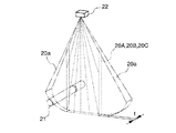
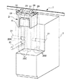
本発明の天井走行搬送装置は、図1に示すように、天井に設置された軌道1と、該軌道1に沿って走行するホイスト付台車3とを備えた天井走行搬送装置において、ホイスト付台車3が、各半導体製造装置7のロードポート8へのウェーハキャリア6の吊り下げ時における、当台車3と各半導体製造装置7のロードポート8間の昇降経路を光探索し、障害物21の有無を検知する複数(本実施の形態では3個の)の障害物検知センサ22を各側壁3aに備え、これら障害物検知センサ22が、前記昇降経路の周囲の複数面(本実施の形態では3面)で監視する構成となっている。
【0015】
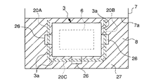
そして、図2に示すように、前記複数面は、ホイスト付台車3側からロードポート8側を向く平面視で前記昇降経路を見た場合に、該昇降経路をホイスト付台車3の走行方向両側から挟み込む位置に配された第1側面20A及び第2側面20Bと、これら第1側面20A及び第2側面20B間位置に配された第3側面20Cとの3側面で形成されている。したがって、前記昇降経路は、これら第1側面20A及び第2側面20B及び第3側面20Cの3側面で、周囲から覆われて監視されるようになっている。なお、前記昇降経路の、前記半導体製造装置7側を向いた側面部分は、半導体製造装置7の盤面7aが面しており、ここからは障害物が昇降経路内に入り込む恐れがない。
以上により、前記昇降経路(同図のウェーハキャリア6が紙面垂直方向に移動する経路)は、第1側面20A及び第2側面20B及び第3側面20Cからなる平面視コ字状の監視面によって周囲から監視される上に、該監視面の開口側面部分は、前記盤面7aによって遮蔽されているので、外部から障害物21が侵入しようとしても、漏れなく検知可能となっている。
【0016】
前記各障害物検知センサ22は、図示されない発光部と受光部とが一体となった光学式の距離センサであり、図3に示すように、該障害物検知センサ22を中心に扇型形状のスキャン範囲20aをスキャンするとともに、そのスキャン範囲20aを2枚の互いに平行な鉛直方向仮想平面(図示せず)で区切るようにして監視範囲20Aとし、この監視範囲20A内のデータをメモリに取り込み、その他の範囲のデータは除去するものである。
このような調整により、障害物検知センサ22とロードポート8との間に形成される略五角形状の光の膜が、監視範囲20Aとして形成される。なお、監視範囲20Aの幅tは、前記発光部からの光線の径で決められるものであり、レーザービームを使用すれば、非常に薄くすることが可能となる。
なお、監視範囲20B及び監視範囲20Cを形成する障害物検知センサ22,22も、監視範囲20Aの障害物検知センサ22と同じ物である。
【0017】
さらに、各監視範囲20A,20B,20Cは、各半導体製造装置7のロードポート8の高さに応じて可変とされている。すなわち、図1に示す各障害物検知センサ22が検知を行う範囲である監視範囲20A,20B,20Cの鉛直方向最大長さLmaxは、障害物検知センサ22から各ロードポート8の上面までの鉛直方向長さLaに応じて各半導体製造装置7毎に可変とされており、いずれの半導体製造装置7にも対応できるようになっている。
【0018】
以上に説明した本実施の形態の天井走行搬送装置によるウェーハキャリア6の吊り下げ時には、各障害物検知センサ22によりそれぞれの監視範囲20A,20B,20C内において障害物21の有無が非接触で監視され、各監視範囲20A,20B,20Cの内のいずれかひとつでも障害物21を発見した場合には、ウェーハキャリア6がこれと干渉する前に、ウェーハキャリア6の吊り下げ動作を停止させる。なお、各障害物検知センサ22は、半導体製造装置7よりも台数の少ないホイスト付台車3側に設けることで、その所要台数が少なくされている。
【0019】
したがって、本実施の形態の天井走行搬送装置によれば、半導体製造装置7よりもはるかに台数の少ないホイスト付台車3側に各障害物検知センサ22を設けたことで、吊り下げ時のウェーハキャリア6が、人や不用意に置かれた物などの障害物21と接触する前にこれを検知して避ける対策を、安価かつ確実に講じることが可能となる。
また、本実施の形態の天井走行搬送装置によれば、前記昇降経路を、第1側面20A及び第2側面20B及び第3側面20Cの少なくとも3側面によって覆うように周囲から監視するので、障害物21が前記昇降経路内に入り込む恐れを効果的に取り除くことも可能である。
【0020】
また、各障害物検知センサ22として光学式のセンサを採用することで、非接触で障害物21の有無の確認がなされるので、障害物21を傷つけることなく監視を行うことも可能となっている。
また、各監視範囲20A,20B,20Cの設定において、これら監視範囲20A,20B,20Cの鉛直方向最大長さLmaxが、各半導体製造装置7のロードポート8と障害物検知センサ22との間の鉛直方向長さLaに合うように予め設定しておくことで、床面Fからの高さHが異なるロードポート8を有する全ての半導体製造装置7に適用することも可能となっている。
【0021】
次に、図4〜図6を参照しながら本発明の第2の実施の形態について以下に説明する。なお、上記第1の実施の形態で説明した図1〜図3と同一構成要素には、同一符号を付し、その説明を省略する。
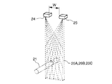
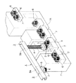
本実施の形態では、図4に示すように、上記第1の実施の形態における単一の障害物検知センサ22の代わりに、一対のスキャン式の障害物検知センサ24及び25を一定間隔Wを置いて各側壁3aにそれぞれ設けたものである。そして、これら障害物検知センサ24及び25が一対となって各側壁3aそれぞれに設けられることで、前記昇降経路を、周囲の複数面(本実施の形態では3面)で監視する構成となっている。
【0022】
そして、図5に示すように、前記複数面は、ホイスト付台車3側からロードポート8側を向く平面視で前記昇降経路を見た場合に、該昇降経路をホイスト付台車3の走行方向両側から挟み込む位置に配された第1側面20A及び第2側面20Bと、これら第1側面20A及び第2側面20B間位置に配された第3側面20Cとの3側面で形成されている。したがって、前記昇降経路は、これら第1側面20A及び第2側面20B及び第3側面20Cの3側面で、周囲から覆われて監視されるようになっている。なお、前記昇降経路の、前記半導体製造装置7側を向いた側面部分は、半導体製造装置7の盤面7aが面しており、ここからは障害物21が昇降経路内に入り込む恐れがない。
以上により、前記昇降経路(同図のウェーハキャリア6が紙面垂直方向に移動する経路)は、第1側面20A及び第2側面20B及び第3側面20Cからなる平面視コ字状の監視面によって周囲から監視される上に、該監視面の開口側面部分は、前記盤面7aによって遮蔽されているので、外部から障害物21が侵入しようとしても、漏れなく検知可能となっている。
【0023】
前記各障害物検知センサ24及び25は、図6に示すように、スキャニングビームと位置検出素子(PSD)により網目状の検出エリアを持つ障害物検知用光電センサであり、光学的三角側距離検出により検知を行うものである。
本実施の形態においても、上記第1の実施の形態と同様の作用効果を得ることが可能である。
【0024】
次に、図7〜図9を参照しながら本発明の第3の実施の形態について以下に説明する。なお、上記第1の実施の形態で説明した図1〜図3と同一構成要素には、同一符号を付し、その説明を省略する。
本実施の形態では、上記第1の実施の形態におけるスキャニング式の障害物検知センサ22の代わりに、図示されない光源や受光素子やレンズの形状によって発光及び受光範囲が下方に向かって広い放物線外形となるように各監視範囲20を形成できる障害物検知センサ26を各側壁3aに1個づつ備えたものである。そして、これら障害物検知センサ6が各側壁3aにそれぞれ設けられることで、前記昇降経路を、周囲の複数面(本実施の形態では3面)で監視する構成となっている。
【0025】
そして、図8に示すように、前記複数面は、ホイスト付台車3側からロードポート8側を向く平面視で前記昇降経路を見た場合に、該昇降経路をホイスト付台車3の走行方向両側から挟み込む位置に配された第1側面20A及び第2側面20Bと、これら第1側面20A及び第2側面20B間位置に配された第3側面20Cとの3側面で形成されている。したがって、前記昇降経路は、これら第1側面20A及び第2側面20B及び第3側面20Cの3側面で、周囲から覆われて監視されるようになっている。なお、前記昇降経路の、前記半導体製造装置7側を向いた側面部分は、半導体製造装置7の盤面7aが面しており、ここからは障害物21が昇降経路内に入り込む恐れがない。
以上により、前記昇降経路(同図のウェーハキャリア6が紙面垂直方向に移動する経路)は、第1側面20A及び第2側面20B及び第3側面20Cからなる平面視コ字状の監視面によって周囲から監視される上に、該監視面の開口側面部分が、前記盤面7aによって遮蔽されているので、外部から障害物21が侵入しようとしても、漏れなく検知可能となっている。
【0026】
前記各障害物検知センサ26は、反射光量を見る反射型であり、ロードポート8の上面で光が反射して誤作動を引き起こさないように、該ロードポート8の上面には、艶消し黒の表面処理27が施されている。
本実施の形態においても、上記第1の実施の形態と同様の作用効果を得ることが可能である。
【0027】
次に、図10〜図12を参照しながら本発明の第4の実施の形態について以下に説明する。なお、上記第1の実施の形態で説明した図1〜図3と同一構成要素には、同一符号を付し、その説明を省略する。
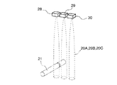
本実施の形態では、上記第1の実施の形態における単一のスキャニング式の障害物検知センサ22の代わりに、3個の測距タイプの障害物検知センサ28、29、30を一組として各側壁3aにそれぞれ一列に設けたものである。そして、これら障害物検知センサ28,29,30が一組として各側壁3aにそれぞれ設けられることで、前記昇降経路を、周囲の複数面(本実施の形態では3面)で監視する構成となっている。
【0028】
そして、図11に示すように、前記複数面は、ホイスト付台車3側からロードポート8側を向く平面視で前記昇降経路を見た場合に、該昇降経路をホイスト付台車3の走行方向両側から挟み込む位置に配された第1側面20A及び第2側面20Bと、これら第1側面20A及び第2側面20B間位置に配された第3側面20Cとの3側面で形成されている。したがって、前記昇降経路は、これら第1側面20A及び第2側面20B及び第3側面20Cの3側面で、周囲から覆われて監視されるようになっている。なお、前記昇降経路の、前記半導体製造装置7側を向いた側面部分は、半導体製造装置7の盤面7aが面しており、ここからは障害物21が昇降経路内に入り込む恐れがない。
以上により、前記昇降経路(同図のウェーハキャリア6が紙面垂直方向に移動する経路)は、第1側面20A及び第2側面20B及び第3側面20Cからなる平面視コ字状の監視面によって周囲から監視される上に、該監視面の開口側面部分は、前記盤面7aによって遮蔽されているので、外部から障害物21が侵入しようとしても、漏れなく検知可能となっている。
【0029】
なお、前記各障害物検知センサ28、29、30は、それぞれの監視エリアの和により、ひとつの監視範囲20A,20B,20Cをそれぞれ形成するものである。
本実施の形態においても、上記第1の実施の形態と同様の作用効果を得ることが可能である。
【0030】
次に、図13〜図15を参照しながら本発明の第5の実施の形態について以下に説明する。なお、上記第1の実施の形態で説明した図1〜図3と同一構成要素には、同一符号を付し、その説明を省略する。
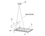
本実施の形態では、図13に示すように、上記第1の実施の形態におけるスキャニング式の障害物検知センサ22の代わりに、各半導体製造装置7のロードポート8上にリフレクタ反射板41を設けると共に、ホイスト付台車3の3つの側壁3aに、リフレクタ反射板41上面の所定の検出エリア42に光を照射して該検出エリア42からの反射光を受光する回帰反射型の障害物検知センサ40をそれぞれ取り付けた構成を採用している。そして、これら障害物検知センサ40を各側壁3aにそれぞれ設けることで、前記昇降経路を、周囲の複数面(本実施の形態では3面)で監視する構成となっている。
【0031】
そして、図14に示すように、前記複数面は、ホイスト付台車3側からロードポート8側を向く平面視で前記昇降経路を見た場合に、該昇降経路をホイスト付台車3の走行方向両側から挟み込む位置に配された第1側面20A及び第2側面20Bと、これら第1側面20A及び第2側面20B間位置に配された第3側面20Cとの3側面で形成されている。したがって、前記昇降経路は、これら第1側面20A及び第2側面20B及び第3側面20Cの3側面で、周囲から覆われて監視されるようになっている。なお、前記昇降経路の、前記半導体製造装置7側を向いた側面部分は、半導体製造装置7の盤面7aが面しており、ここからは障害物21が昇降経路内に入り込む恐れがない。
以上により、前記昇降経路(同図のウェーハキャリア6が紙面垂直方向に移動する経路)は、第1側面20A及び第2側面20B及び第3側面20Cからなる平面視コ字状の監視面によって周囲から監視される上に、該監視面の開口側面部分は、前記盤面7aによって遮蔽されているので、外部から障害物21が侵入しようとしても、漏れなく検知可能となっている。
【0032】
図5に示す前記各障害物検知センサ40は、図示されない制御手段に接続されている。この制御手段は、障害物検知センサ40が検出エリア42の全面から反射光を受光した場合には、出力をONとし、「リフレクタ反射板41の全面の存在が確認できたので、キャリア6が移載可能である」と判断する。逆に、障害物検知センサ40において検出エリア42の全面から反射光が得られない場合(すなわち、障害物検知センサ40側から見て、検出エリア42のどこか一箇所でも障害物21が遮ったり、リフレクタ反射板41が真下に存在しない場合)には、出力をOFFとし、「キャリア6の移載は不可能である」と判断する。
【0033】
なお、これら障害物検知センサ40は、各半導体製造装置7の構造により検出したい範囲が狭くなってしまう場合には、これに備えられている検出エリア選択機能を使用することにより、検出エリア幅を制限させることも可能となっている。逆に、大型の天井走行搬送装置など、検出エリアを広げる必要がある場合には、各障害物検知センサ40に備えられている相互干渉防止機能(投光周波数の切り替え機能)を使用することによって、各側壁3a毎に複数の障害物検知センサ40を用いて広い検出エリアをカバーすることも可能となる。
また、本実施の形態ではリフレクタ反射板41をロードポート8上に設ける構成を採用しているが、このロードポート8上への設置が難しい場合には、このロードポート8を平面視した場合の該ロードポート8周囲部分の床面F上(図13に二点鎖線で示す設置場所45)に設けるようにしても良い。
本実施の形態においても、上記第1の実施の形態と同様の作用効果を得ることが可能である。
【0034】
なお、上記説明の第1から第5の実施の形態においては、前記昇降経路を周囲から監視する前記複数面を、図16(a)の平面図に示すように3側面で監視する構成としたが、これに限らず、4側面以上で監視する構成を採用しても良い。さらには、例えば図16(b)または図16(c)に示すように、前記ホイスト付台車3の走行方向前進側に位置する前進側側面20D及び、前記昇降経路を挟んで前進側側面20Dと反対側に位置する後退側側面20Eのいずれか1側面と、製造装置7を正面視した場合に前記昇降経路より手前側に位置する1側面(手前側側面20F)との少なくとも2側面で監視する構成を採用しても良い。
【0035】
この構成によれば、例えば図16(b)及び図16(c)に示すように、平面視した場合のロードポート8が横に長い形状で、かつ該ロードポート8上の長手方向一端側(図16(b)では紙面右端側。図16(c)では紙面左端側)に偏った位置でキャリア6の昇降作業を行うような場合には、前進側側面20Dまたは後退側側面20Eのいずれか1側面と、手前側側面20Fの1側面との少なくとも2側面で十分に昇降経路周囲を監視することができる。すなわち、前進側側面20Dもしくは後退側側面20Eのいずれかの内、前記長手方向一端側に面する1側面を監視面の一部として選ぶことで、この1側面と手前側側面20Fの1側面とによって形成される平面視略L字状の監視領域で昇降経路周囲側面の半分が覆われて障害物侵入の有無が監視される。このとき、ロードポート8の長手方向他端側から昇降経路までは所定距離が有るので、この方向からの障害物侵入の恐れを無視することができる。したがって、このような場合には、設置すべき障害物検知センサの個数を減らして、天井走行搬送装置の製造コストをより下げることが可能となる。
【0036】
また、上記説明の第1から第5の実施の形態に示した各障害物検知センサ22、24、25、26、28、29、30、40は、ホイスト付台車3の3つの側壁3aにそれぞれ設けた構成としたが、これに限らず、平面視した場合に前記昇降経路を複数面で監視できれば良く、前記ウェーハキャリア6及びこの昇降経路を避けるようにした上で、ホイスト付台車3の下端に設ける構成を採用しても良い。
【0037】
また、上記説明の第1から第5の実施の形態に示した各障害物検知センサ22、24、25、26、28、29、30、40のタイプに限らず、その他のタイプの光学式センサを採用しても良い。
また、上記説明の第4の実施の形態においては、3個の測距タイプの障害物検知センサ28、29、30を一組として各側壁3aに設ける構成を採用したが、この代わりに、上記第5の実施の形態で説明した回帰反射型の障害物検知センサ40と同様のものを各側壁3aに複数個(例えば3個)設けると共に、ロードポート8上に前記リフレクタ反射板41と同様のものを設けて(図示せず)、これら障害物検知センサの監視エリアの和によって、各監視範囲20を形成する構成を採用しても良い。この場合においても、上記第1の実施の形態と同様の作用効果を得ることが可能である。なお、この場合のリフレクタ反射板41の配置としては、ロードポート8上への設置が難しい場合には、このロードポート8を平面した場合の周囲部分に位置する床面F上に設けるようにしても良い。
【0038】
また、上記説明の第4の実施の形態において、各側壁3a毎の障害物検知センサ28、29、30の個数は3個としたが、これに限らず、必要十分な広さまたは大きさの監視範囲20を形成できれば良く、2個または4個以上としても良い。
また、上記説明の第1から第5の実施の形態においては、本発明の天井走行搬送装置を、半導体ウェーハを処理して半導体デバイスの製造を行う半導体製造設備に設けた場合を例に説明を行ったが、これに限らず、工場におけるファクトリーオートメーションライン等、その他の設備にも適用可能である。
【0039】
【発明の効果】
本発明の請求項1記載の天井走行搬送装置は、ホイスト付台車が、当台車と各製造装置のロードポート間との昇降経路を光探索し障害物の有無を検知する障害物検知センサを備え、障害物検知センサが、昇降経路の周囲を複数面で監視する構成を採用した。この構成によれば、製造装置よりもはるかに台数の少ないホイスト付台車側に障害物検知センサを設けることで、吊り下げ時の搬送物が、人や不用意に置かれた物等の障害物と接触する前にこれを検知して避ける対策を、安価かつ確実に講じることが可能となる。
【0040】
また、請求項2記載の天井走行搬送装置は、前記複数面が、ホイスト付台車側からロードポート側を向く視線で昇降経路を見た場合に、該昇降経路をホイスト付台車の走行方向両側から挟み込む位置に配された第1側面及び第2側面と、これら第1側面及び第2側面間位置に配された第3側面との少なくとも3側面で形成されている構成を採用した。この構成によれば、昇降経路は、第1側面及び第2側面及び第3側面の少なくとも3側面によって覆われるように周囲から監視されるので、障害物が昇降経路内に入り込む恐れを効果的に取り除くことが可能となる。
【0041】
また、請求項3記載の天井走行搬送装置は、前記複数面が、前記ホイスト付台車の走行方向前進側に位置する前進側側面及び、前記昇降経路を挟んで前記前進側側面と反対側に位置する後退側側面のいずれか1側面と、前記製造装置を正面視した場合に前記昇降経路より手前側に位置する1側面との少なくとも2側面で形成されている構成を採用した。この構成によれば、例えば、平面視した場合のロードポートが横に長い形状で、かつ該ロードポート上の長手方向一端側に偏った位置で搬送物の昇降作業を行うような場合には、前記前進側側面または前記後退側側面のいずれか1側面と、前記手前側の1側面との少なくとも2側面で十分に昇降経路周囲を監視することができる。すなわち、前記前進側側面もしくは前記後退側側面のいずれかの内、前記長手方向一端側に面する1側面を監視面の一部として選ぶことで、この1側面と前記手前側の1側面とによって形成される平面視略L字状の監視領域で昇降経路の半分が覆われて障害物侵入の有無が監視される。このとき、ロードポートの長手方向他端側から昇降経路までは所定距離が有るので、この方向からの障害物侵入の恐れを無視することができる。したがって、このような場合には、設置すべき障害物検知センサの個数を減らして、天井走行搬送装置の製造コストをより下げることが可能となる。
【図面の簡単な説明】
【図1】 本発明の天井走行搬送装置の第1の実施の形態を示す図であって、斜視図である。
【図2】 同天井走行搬送装置における各障害物検知センサの検知範囲を示す平面図である。
【図3】 同天井走行搬送装置における障害物検知センサ単体の検知範囲を説明する斜視図である。
【図4】 本発明の天井走行搬送装置の第2の実施の形態を示す図であって、斜視図である。
【図5】 同天井走行搬送装置における各障害物検知センサの検知範囲を示す平面図である。
【図6】 同天井走行搬送装置における障害物検知センサ単体の検知範囲を説明する斜視図である。
【図7】 本発明の天井走行搬送装置の第3の実施の形態を示す図であって、斜視図である。
【図8】 同天井走行搬送装置における各障害物検知センサの検知範囲を示す平面図である。
【図9】 同天井走行搬送装置における障害物検知センサ単体の検知範囲を説明する斜視図である。
【図10】 本発明の天井走行搬送装置の第4の実施の形態を示す図であって、斜視図である。
【図11】 同天井走行搬送装置における各障害物検知センサの検知範囲を示す平面図である。
【図12】 同天井走行搬送装置における障害物検知センサ単体の検知範囲を説明する斜視図である。
【図13】 本発明の天井走行搬送装置の第5の実施の形態を示す図であって、斜視図である。
【図14】 同天井走行搬送装置における各障害物検知センサの検知範囲を示す平面図である。
【図15】 同天井走行搬送装置における障害物検知センサ単体の検知範囲を説明する斜視図である。
【図16】 (a)は本発明の天井走行搬送装置の第1〜第5の実施の形態における監視範囲を示す平面図であり、(b)及び(c)は、その変形例を示す平面図である。
【図17】 従来の天井走行搬送装置を示す図であって、斜視図である。
【図18】 従来の他の天井走行搬送装置を示す図であって、斜視図である。
【図19】 従来の他の天井走行搬送装置を示す図であって、斜視図である。
【図20】 従来の他の天井走行搬送装置を示す図であって、斜視図である。
【図21】 従来の他の天井走行搬送装置を示す図であって、斜視図である。
【符号の説明】
1・・・軌道
3・・・ホイスト付台車
7・・・半導体製造装置(製造装置)
8・・・ロードポート
20A・・・第1側面
20B・・・第2側面
20C・・・第3側面
20D・・・前進側側面
20E・・・後退側側面
20F・・・手前側側面(手前側に位置する1側面)
21・・・障害物
22、24、25、26、28、29、30、40・・・障害物検知センサ[0001]
BACKGROUND OF THE INVENTION
The present invention relates to a ceiling traveling transport apparatus that travels on a track disposed on a ceiling and transports a transported object between semiconductor manufacturing apparatuses disposed in a clean room or the like in a suspended state.
[0002]
[Prior art]
In a manufacturing facility for manufacturing semiconductor devices, a transfer device that automatically transfers a semiconductor wafer between various devices is used. As one of this type of transfer device, an orbital transfer device is used. is there. A general track-type transfer device is configured to run a transfer carriage on a track installed on a ceiling or a floor, and usually includes a manufacturing device for processing various semiconductor wafers on the side of the track. ing.
In general, a semiconductor device is manufactured through a process of hundreds of processes in which a semiconductor wafer such as silicon is transferred between various semiconductor manufacturing apparatuses (wafer processing apparatus, storage apparatus, work table, buffer apparatus, etc.).
[0003]
An example of the overhead traveling transport device in which the track is arranged on the ceiling will be described below with reference to FIG. For example, in a ceiling traveling transport apparatus for a semiconductor manufacturing apparatus in a clean room, a
A
By the way, in the clean room, as shown in the figure, a plurality of
[0004]
The
And it stops above other
[0005]
By the way, the overhead traveling transfer device raises or lowers the transfer object such as the
[0006]
An example of this conventional countermeasure plan will be described below with reference to FIGS.
These countermeasure proposals were announced in a joint guidance between J300 (Japan 300mm Semiconductor Technology Conference) and I300I (International 300mm Initiative). In addition, the same code | symbol is attached | subjected to the same component as what was demonstrated in FIG. 17, and the description is abbreviate | omitted.
[0007]
FIG. 18 shows that an
In FIG. 19, when a
[0008]
In FIG. 20, the
FIG. 21 is provided with an
[0009]
[Problems to be solved by the invention]
By the way, the conventional countermeasures A, B, C, and D described above are not realistic because they have the following problems.
In other words, the countermeasure plan A is that the driver must monitor all of the
Further, there are many countermeasure plans B, C, and D (generally, 300 to 400 units. Incidentally, in this case, the hoist-equipped
[0010]
The present invention has been made in view of the above circumstances, and has the following objects. In other words, it is possible to take cheap and reliable measures for overhead traveling so that the suspended material can be detected before it comes into contact with an obstacle such as a person or a careless object. The purpose is to provide a device.
[0011]
[Means for Solving the Problems]
The overhead traveling transport apparatus of the present invention employs the following means in order to solve the above problems. That is, the overhead traveling transport device according to
[0012]
Claims5The overhead traveling conveyance device according to claim 1.Any one of -4In the above-described overhead traveling transport device, when the hoisting path is viewed from a line of sight toward the load port side from the hoisted carriage side, the hoisting path is sandwiched from both sides in the running direction of the hoisted carriage. The first side surface and the second side surface arranged at positions, and the third side surface arranged at a position between the first side surface and the second side surface, are formed. Claims above5According to the described overhead traveling transport device, the lifting path is monitored from the surroundings so as to be covered by at least three side surfaces of the first side surface, the second side surface, and the third side surface, and therefore an obstacle may enter the lifting route. Can be effectively removed.
[0013]
Claims6The overhead traveling conveyance device according to claim 1.Any one of -4In the above-described overhead traveling transport device, the plurality of surfaces include a forward side surface located on the forward side in the traveling direction of the carriage with the hoist, and a backward side surface located on the opposite side of the forward side surface across the lifting path. It is formed by at least two side surfaces of any one side surface and one side surface located on the near side of the lifting path when the manufacturing apparatus is viewed from the front. Claims above6According to the above described overhead traveling conveyance device, for example, the load port in a plan view has a horizontally long shape and lifts and lowers the conveyed object at a position biased to one end side in the longitudinal direction on the load port. In this case, it is possible to sufficiently monitor the periphery of the lifting path on at least two side surfaces of either the forward side surface or the backward side surface and the one side surface on the near side. That is, by selecting one of the forward side surface and the backward side surface facing one end in the longitudinal direction as a part of the monitoring surface, the one side surface and the one side surface on the near side Half of the elevating path is covered with the monitoring area formed in a substantially L shape in plan view, and the presence or absence of an obstacle is monitored. At this time, since there is a predetermined distance from the other longitudinal end side of the load port to the lifting path, the risk of obstacle intrusion from this direction can be ignored. Therefore, in such a case, the number of obstacle detection sensors to be installed can be reduced, and the manufacturing cost of the overhead traveling transport device can be reduced.In addition, in the overhead traveling transport apparatus according to
[0014]
DETAILED DESCRIPTION OF THE INVENTION
A first embodiment of the present invention will be described below with reference to FIGS. In addition, the same code | symbol is attached | subjected to the same component as FIG. 17 demonstrated by the prior art, and the description is abbreviate | omitted.
As shown in FIG. 1, the overhead traveling transport apparatus according to the present invention is an overhead traveling transport apparatus including a
[0015]
As shown in FIG. 2, when the hoisting path is viewed in plan view from the
As described above, the up / down path (the path along which the
[0016]
Each
By such adjustment, a substantially pentagonal light film formed between the
The
[0017]
Furthermore, each of the monitoring ranges 20A, 20B, and 20C is variable according to the height of the
[0018]
When the
[0019]
Therefore, according to the overhead traveling transfer device of the present embodiment, the obstacle
Further, according to the overhead traveling transport device of the present embodiment, since the lifting path is monitored from the surroundings so as to be covered by at least three side surfaces of the
[0020]
In addition, by employing an optical sensor as each
Further, in the setting of each
[0021]
Next, a second embodiment of the present invention will be described below with reference to FIGS. In addition, the same code | symbol is attached | subjected to the same component as FIGS. 1-3 demonstrated in the said 1st Embodiment, and the description is abbreviate | omitted.
In the present embodiment, as shown in FIG. 4, instead of the single
[0022]
And as shown in FIG. 5, when the said raising / lowering path | route is seen in the planar view which faces the
As described above, the up / down path (the path along which the
[0023]
As shown in FIG. 6, each of the
Also in this embodiment, it is possible to obtain the same effect as that of the first embodiment.
[0024]
Next, a third embodiment of the present invention will be described below with reference to FIGS. In addition, the same code | symbol is attached | subjected to the same component as FIGS. 1-3 demonstrated in the said 1st Embodiment, and the description is abbreviate | omitted.
In the present embodiment, instead of the scanning-type
[0025]
And as shown in FIG. 8, when the said raising / lowering path | route is seen in the planar view which faces the
As described above, the up / down path (the path along which the
[0026]
Each of the
Also in this embodiment, it is possible to obtain the same effect as that of the first embodiment.
[0027]
Next, a fourth embodiment of the present invention will be described below with reference to FIGS. In addition, the same code | symbol is attached | subjected to the same component as FIGS. 1-3 demonstrated in the said 1st Embodiment, and the description is abbreviate | omitted.
In this embodiment, instead of the single scanning type
[0028]
And as shown in FIG. 11, when the said raising / lowering path | route sees the said raising / lowering path | route in planar view which faces the
As described above, the up / down path (the path along which the
[0029]
Each of the
Also in this embodiment, it is possible to obtain the same effect as that of the first embodiment.
[0030]
Next, a fifth embodiment of the present invention will be described below with reference to FIGS. In addition, the same code | symbol is attached | subjected to the same component as FIGS. 1-3 demonstrated in the said 1st Embodiment, and the description is abbreviate | omitted.
In the present embodiment, as shown in FIG. 13, a
[0031]
And as shown in FIG. 14, when the said raising / lowering path | route is seen by the planar view which faces the
As described above, the up / down path (the path along which the
[0032]
Each
[0033]
In addition, when the range which wants to detect these
Further, in the present embodiment, a configuration in which the
Also in this embodiment, it is possible to obtain the same effect as that of the first embodiment.
[0034]
In the first to fifth embodiments described above, the plurality of surfaces for monitoring the elevating path from the surroundings are monitored on three sides as shown in the plan view of FIG. However, the configuration is not limited to this, and a configuration in which monitoring is performed on four or more side surfaces may be employed. Furthermore, for example, as shown in FIG. 16B or FIG. 16C, a
[0035]
According to this configuration, for example, as shown in FIGS. 16B and 16C, the
[0036]
Further, each
[0037]
Further, the present invention is not limited to the types of the
Further, in the fourth embodiment described above, a configuration in which three distance measuring type
[0038]
In the fourth embodiment described above, the number of
In the first to fifth embodiments described above, the overhead traveling transfer apparatus according to the present invention is described as an example in the case where it is provided in a semiconductor manufacturing facility that processes semiconductor wafers and manufactures semiconductor devices. Although it went, it is applicable not only to this but other facilities, such as a factory automation line in a factory.
[0039]
【The invention's effect】
The overhead traveling conveyance device according to
[0040]
Further, in the overhead traveling transport device according to
[0041]
The overhead traveling transport device according to
[Brief description of the drawings]
FIG. 1 is a perspective view showing a first embodiment of an overhead traveling transport apparatus according to the present invention.
FIG. 2 is a plan view showing a detection range of each obstacle detection sensor in the overhead traveling conveyance device.
FIG. 3 is a perspective view for explaining a detection range of an obstacle detection sensor alone in the ceiling traveling conveyance device.
FIG. 4 is a perspective view showing a second embodiment of the overhead traveling transport device of the present invention.
FIG. 5 is a plan view showing a detection range of each obstacle detection sensor in the ceiling traveling conveyance device.
FIG. 6 is a perspective view illustrating a detection range of a single obstacle detection sensor in the ceiling traveling conveyance device.
FIG. 7 is a perspective view showing a third embodiment of the overhead traveling transport apparatus of the present invention.
FIG. 8 is a plan view showing a detection range of each obstacle detection sensor in the ceiling traveling conveyance device.
FIG. 9 is a perspective view illustrating a detection range of a single obstacle detection sensor in the ceiling traveling conveyance device.
FIG. 10 is a perspective view showing a fourth embodiment of the overhead traveling transport apparatus of the present invention.
FIG. 11 is a plan view showing a detection range of each obstacle detection sensor in the overhead traveling conveyance device.
FIG. 12 is a perspective view for explaining a detection range of a single obstacle detection sensor in the ceiling traveling conveyance device.
FIG. 13 is a perspective view showing a fifth embodiment of the overhead traveling transport apparatus of the present invention.
FIG. 14 is a plan view showing a detection range of each obstacle detection sensor in the ceiling traveling conveyance device.
FIG. 15 is a perspective view illustrating a detection range of a single obstacle detection sensor in the ceiling traveling conveyance device.
FIG. 16A is a plan view showing a monitoring range in the first to fifth embodiments of the overhead traveling transport apparatus of the present invention, and FIGS. FIG.
FIG. 17 is a perspective view showing a conventional overhead traveling transport device.
FIG. 18 is a perspective view showing another conventional overhead traveling transport device.
FIG. 19 is a perspective view showing another conventional overhead traveling apparatus.
FIG. 20 is a perspective view showing another conventional overhead traveling transport device.
FIG. 21 is a perspective view showing another conventional overhead traveling apparatus.
[Explanation of symbols]
1 ... Orbit
3 ... Cart with hoist
7 ... Semiconductor manufacturing equipment (manufacturing equipment)
8 ... Load port
20A ... 1st side
20B ... 2nd side
20C ... Third side
20D ... Advance side
20E ・ ・ ・ Back side
20F: Front side (one side located on the front)
21 ... Obstacle
22, 24, 25, 26, 28, 29, 30, 40 ... obstacle detection sensor
Claims (6)
前記ホイスト付台車は、その複数の側壁のそれぞれに、当台車と各製造装置のロードポート間との昇降経路を光探索し障害物の有無を検知する障害物検知センサを備え、
前記障害物検知センサは、前記側壁に直交する方向から見て当該障害物検知センサを中心とする扇形形状を有するスキャン範囲をスキャンする光学式センサであり、
前記スキャン範囲のそれぞれにおいて前記側壁の幅方向に関して当該側壁より外側の少なくとも一部を除いた範囲を監視することにより、前記昇降経路の周囲を複数面で監視することを特徴とする天井走行搬送装置。In a ceiling traveling transport device comprising a track installed on a ceiling and a cart with a hoist that travels along the track,
The bogie with a hoist includes an obstacle detection sensor for detecting the presence or absence of an obstacle by optically searching for an ascending / descending path between the carriage and a load port of each manufacturing apparatus on each of the plurality of side walls .
The obstacle detection sensor is an optical sensor that scans a scan range having a fan shape centered on the obstacle detection sensor when viewed from a direction orthogonal to the side wall,
An overhead traveling transport apparatus that monitors the periphery of the lifting path on a plurality of surfaces by monitoring a range excluding at least a part outside the sidewall in the width direction of the sidewall in each of the scan ranges. .
前記複数の側壁のそれぞれに1つずつ前記障害物検知センサが設けられており、
前記監視する範囲のそれぞれが、前記側壁に直交する方向から見て五角形の形状を有していることを特徴とする天井走行搬送装置。 In the overhead traveling conveyance apparatus according to claim 1 ,
The obstacle detection sensor is provided one by one on each of the plurality of side walls,
Each of the ranges to be monitored has a pentagonal shape as viewed from a direction orthogonal to the side wall.
前記ホイスト付台車は、その複数の側壁のそれぞれに、当台車と各製造装置のロードポート間との昇降経路を光探索し障害物の有無を検知する複数の障害物検知センサを備え、
前記複数の障害物検知センサの検出範囲は、前記複数の側壁のそれぞれにおいて当該側壁の幅方向に関して互いに異なる位置に配置され、
前記検出範囲のそれぞれを監視することにより前記昇降経路の周囲を複数面で監視することを特徴とする天井走行搬送装置。 In a ceiling traveling transport device comprising a track installed on a ceiling and a cart with a hoist that travels along the track,
The cart with hoist includes, on each of the plurality of side walls, a plurality of obstacle detection sensors that detect the presence or absence of an obstacle by optically searching for an ascending / descending path between the carriage and the load port of each manufacturing apparatus,
The detection ranges of the plurality of obstacle detection sensors are arranged at different positions with respect to the width direction of the side walls in each of the plurality of side walls,
An overhead traveling conveyance device that monitors each of the detection ranges on a plurality of surfaces by monitoring each of the detection ranges.
前記複数の障害物検知センサは、前記複数の側壁のそれぞれにおいて当該側壁の幅方向に沿って配列されていることを特徴とする天井走行搬送装置。 In the overhead traveling conveyance apparatus according to claim 3,
The plurality of obstacle detection sensors are arranged along the width direction of each of the plurality of side walls.
前記複数面は、前記ホイスト付台車側から前記ロードポート側を向く視線で前記昇降経路を見た場合に、該昇降経路を前記ホイスト付台車の走行方向両側から挟み込む位置に配された第1側面及び第2側面と、これら第1側面及び第2側面間位置に配された第3側面との少なくとも3側面で形成されていることを特徴とする天井走行搬送装置。In the overhead traveling conveyance apparatus of any one of Claims 1-4 ,
The plurality of surfaces are arranged at positions where the hoisting path is sandwiched from both sides in the running direction of the hoisting carriage when the hoisting path is viewed from a line of sight toward the load port side from the hoisting carriage side. And an overhead traveling transport device, characterized in that it is formed of at least three side surfaces including a second side surface and a third side surface disposed between the first side surface and the second side surface.
前記複数面は、前記ホイスト付台車の走行方向前進側に位置する前進側側面及び、前記昇降経路を挟んで前記前進側側面と反対側に位置する後退側側面のいずれか1側面と、前記製造装置を正面視した場合に前記昇降経路より手前側に位置する1側面との少なくとも2側面で形成されていることを特徴とする天井走行搬送装置。In the overhead traveling conveyance apparatus of any one of Claims 1-4 ,
The plurality of surfaces include any one of a forward side surface located on the forward side in the traveling direction of the carriage with the hoist and a backward side surface located on the opposite side of the forward side surface across the lifting path, and the manufacturing An overhead traveling conveyance device, characterized in that it is formed of at least two side surfaces, one side surface located on the near side of the lifting path when the device is viewed from the front.
Priority Applications (1)
| Application Number | Priority Date | Filing Date | Title |
|---|---|---|---|
| JP2000073163A JP4465415B2 (en) | 2000-03-15 | 2000-03-15 | Ceiling traveling transfer device |
Applications Claiming Priority (1)
| Application Number | Priority Date | Filing Date | Title |
|---|---|---|---|
| JP2000073163A JP4465415B2 (en) | 2000-03-15 | 2000-03-15 | Ceiling traveling transfer device |
Publications (2)
| Publication Number | Publication Date |
|---|---|
| JP2001261284A JP2001261284A (en) | 2001-09-26 |
| JP4465415B2 true JP4465415B2 (en) | 2010-05-19 |
Family
ID=18591453
Family Applications (1)
| Application Number | Title | Priority Date | Filing Date |
|---|---|---|---|
| JP2000073163A Expired - Fee Related JP4465415B2 (en) | 2000-03-15 | 2000-03-15 | Ceiling traveling transfer device |
Country Status (1)
| Country | Link |
|---|---|
| JP (1) | JP4465415B2 (en) |
Cited By (1)
| Publication number | Priority date | Publication date | Assignee | Title |
|---|---|---|---|---|
| US20220344188A1 (en) * | 2020-05-29 | 2022-10-27 | Changxin Memory Technologies, Inc. | Overhead buffer double-entry detection system and method thereof |
Families Citing this family (10)
| Publication number | Priority date | Publication date | Assignee | Title |
|---|---|---|---|---|
| JP5388045B2 (en) * | 2007-07-24 | 2014-01-15 | 北陽電機株式会社 | Transport cart and optical distance measuring device |
| JP5380747B2 (en) * | 2009-09-16 | 2014-01-08 | 株式会社日立製作所 | Monitoring system and monitoring method under suspended load |
| JP5488882B2 (en) * | 2009-10-08 | 2014-05-14 | 株式会社日立製作所 | Fixed video display system |
| JP5821171B2 (en) * | 2010-09-07 | 2015-11-24 | 村田機械株式会社 | Transport system |
| WO2014017221A1 (en) | 2012-07-26 | 2014-01-30 | 村田機械株式会社 | Overhead traveling vehicle system and transfer control method for overhead traveling vehicle system |
| JP6007880B2 (en) * | 2013-10-10 | 2016-10-12 | 株式会社ダイフク | Ceiling transport vehicle |
| CN104760892B (en) * | 2014-01-06 | 2016-09-28 | 中国特种设备检测研究院 | Portal crane health monitoring and forecast visualization system |
| WO2022176288A1 (en) * | 2021-02-17 | 2022-08-25 | 村田機械株式会社 | Overhead transport vehicle |
| CN114644297A (en) * | 2022-03-11 | 2022-06-21 | 济南恒起工程机械有限公司 | Obstacle avoidance and early warning method of tower crane |
| CN114684525B (en) * | 2022-05-31 | 2022-08-12 | 徐州太平洋印务有限公司 | Suspension device for storing printed matter warehouse |
-
2000
- 2000-03-15 JP JP2000073163A patent/JP4465415B2/en not_active Expired - Fee Related
Cited By (2)
| Publication number | Priority date | Publication date | Assignee | Title |
|---|---|---|---|---|
| US20220344188A1 (en) * | 2020-05-29 | 2022-10-27 | Changxin Memory Technologies, Inc. | Overhead buffer double-entry detection system and method thereof |
| US12191180B2 (en) * | 2020-05-29 | 2025-01-07 | Changxin Memory Technologies, Inc. | Overhead buffer double-entry detection system and method thereof |
Also Published As
| Publication number | Publication date |
|---|---|
| JP2001261284A (en) | 2001-09-26 |
Similar Documents
| Publication | Publication Date | Title |
|---|---|---|
| JP3375907B2 (en) | Ceiling traveling transfer device | |
| JP3371897B2 (en) | Ceiling traveling transfer device | |
| KR100729986B1 (en) | Auto-carrying system | |
| US6019563A (en) | Automated guided vehicle | |
| US6092678A (en) | Overhead hoist transfer | |
| JP4465415B2 (en) | Ceiling traveling transfer device | |
| KR102432628B1 (en) | Article support deviec | |
| US20170194182A1 (en) | Carrier transport system and transport method | |
| US6791074B2 (en) | Light curtain system for establishing a protective light curtain, tool and system for processing objects and method for loading/unloading a tool | |
| JP2008137738A (en) | Overhead traveling carrying device | |
| US6113341A (en) | Tracking cart system | |
| TW202237510A (en) | Elevated transport vehicle | |
| JPH1124750A (en) | Unmanned transfer device | |
| CN113371614B (en) | Automated crane collision avoidance system and method | |
| KR100636601B1 (en) | Transfer robot driving at a ceiling | |
| TW202045423A (en) | Stocker system | |
| JPH05304198A (en) | Conveyor | |
| JP2006323435A (en) | Obstacle detection device for transport cart | |
| JP3959778B2 (en) | Automated guided vehicle | |
| TWI834958B (en) | Mobile vehicle system | |
| KR20210004850A (en) | Inspection system | |
| US20240083689A1 (en) | Conveying apparatus and conveying method | |
| JPH09115988A (en) | Method and apparatus for detecting cassette | |
| KR20040054054A (en) | Indexer for cassette of equipment for fabricating of semiconductor | |
| US12543532B2 (en) | Transport vehicle |
Legal Events
| Date | Code | Title | Description |
|---|---|---|---|
| A621 | Written request for application examination |
Free format text: JAPANESE INTERMEDIATE CODE: A621 Effective date: 20060831 |
|
| RD04 | Notification of resignation of power of attorney |
Free format text: JAPANESE INTERMEDIATE CODE: A7424 Effective date: 20090507 |
|
| A977 | Report on retrieval |
Free format text: JAPANESE INTERMEDIATE CODE: A971007 Effective date: 20090514 |
|
| A131 | Notification of reasons for refusal |
Free format text: JAPANESE INTERMEDIATE CODE: A131 Effective date: 20090526 |
|
| RD04 | Notification of resignation of power of attorney |
Free format text: JAPANESE INTERMEDIATE CODE: A7424 Effective date: 20090501 |
|
| RD02 | Notification of acceptance of power of attorney |
Free format text: JAPANESE INTERMEDIATE CODE: A7422 Effective date: 20090622 |
|
| A521 | Written amendment |
Free format text: JAPANESE INTERMEDIATE CODE: A523 Effective date: 20090724 |
|
| TRDD | Decision of grant or rejection written | ||
| A01 | Written decision to grant a patent or to grant a registration (utility model) |
Free format text: JAPANESE INTERMEDIATE CODE: A01 Effective date: 20090818 |
|
| A61 | First payment of annual fees (during grant procedure) |
Free format text: JAPANESE INTERMEDIATE CODE: A61 Effective date: 20090831 |
|
| A711 | Notification of change in applicant |
Free format text: JAPANESE INTERMEDIATE CODE: A711 Effective date: 20091023 |
|
| R155 | Notification before disposition of declining of application |
Free format text: JAPANESE INTERMEDIATE CODE: R155 |
|
| A521 | Written amendment |
Free format text: JAPANESE INTERMEDIATE CODE: A821 Effective date: 20091117 |
|
| RD02 | Notification of acceptance of power of attorney |
Free format text: JAPANESE INTERMEDIATE CODE: A7422 Effective date: 20091117 |
|
| A01 | Written decision to grant a patent or to grant a registration (utility model) |
Free format text: JAPANESE INTERMEDIATE CODE: A01 |
|
| A521 | Written amendment |
Free format text: JAPANESE INTERMEDIATE CODE: A523 Effective date: 20100113 |
|
| R150 | Certificate of patent or registration of utility model |
Ref document number: 4465415 Country of ref document: JP Free format text: JAPANESE INTERMEDIATE CODE: R150 Free format text: JAPANESE INTERMEDIATE CODE: R150 |
|
| FPAY | Renewal fee payment (event date is renewal date of database) |
Free format text: PAYMENT UNTIL: 20130305 Year of fee payment: 3 |
|
| FPAY | Renewal fee payment (event date is renewal date of database) |
Free format text: PAYMENT UNTIL: 20130305 Year of fee payment: 3 |
|
| S111 | Request for change of ownership or part of ownership |
Free format text: JAPANESE INTERMEDIATE CODE: R313111 |
|
| FPAY | Renewal fee payment (event date is renewal date of database) |
Free format text: PAYMENT UNTIL: 20130305 Year of fee payment: 3 |
|
| R350 | Written notification of registration of transfer |
Free format text: JAPANESE INTERMEDIATE CODE: R350 |
|
| FPAY | Renewal fee payment (event date is renewal date of database) |
Free format text: PAYMENT UNTIL: 20130305 Year of fee payment: 3 |
|
| FPAY | Renewal fee payment (event date is renewal date of database) |
Free format text: PAYMENT UNTIL: 20140305 Year of fee payment: 4 |
|
| R250 | Receipt of annual fees |
Free format text: JAPANESE INTERMEDIATE CODE: R250 |
|
| R250 | Receipt of annual fees |
Free format text: JAPANESE INTERMEDIATE CODE: R250 |
|
| R250 | Receipt of annual fees |
Free format text: JAPANESE INTERMEDIATE CODE: R250 |
|
| R250 | Receipt of annual fees |
Free format text: JAPANESE INTERMEDIATE CODE: R250 |
|
| R250 | Receipt of annual fees |
Free format text: JAPANESE INTERMEDIATE CODE: R250 |
|
| R250 | Receipt of annual fees |
Free format text: JAPANESE INTERMEDIATE CODE: R250 |
|
| R250 | Receipt of annual fees |
Free format text: JAPANESE INTERMEDIATE CODE: R250 |
|
| LAPS | Cancellation because of no payment of annual fees |